EP3383034A1 - Conversion de longueur d'onde à distance dans un dispositif d'éclairage - Google Patents
Conversion de longueur d'onde à distance dans un dispositif d'éclairage Download PDFInfo
- Publication number
- EP3383034A1 EP3383034A1 EP18167801.2A EP18167801A EP3383034A1 EP 3383034 A1 EP3383034 A1 EP 3383034A1 EP 18167801 A EP18167801 A EP 18167801A EP 3383034 A1 EP3383034 A1 EP 3383034A1
- Authority
- EP
- European Patent Office
- Prior art keywords
- light
- wavelength range
- color separation
- light source
- illumination device
- Prior art date
- Legal status (The legal status is an assumption and is not a legal conclusion. Google has not performed a legal analysis and makes no representation as to the accuracy of the status listed.)
- Granted
Links
Images

Classifications
-
- G—PHYSICS
- G02—OPTICS
- G02B—OPTICAL ELEMENTS, SYSTEMS OR APPARATUS
- G02B27/00—Optical systems or apparatus not provided for by any of the groups G02B1/00 - G02B26/00, G02B30/00
- G02B27/10—Beam splitting or combining systems
- G02B27/14—Beam splitting or combining systems operating by reflection only
- G02B27/149—Beam splitting or combining systems operating by reflection only using crossed beamsplitting surfaces, e.g. cross-dichroic cubes or X-cubes
-
- G—PHYSICS
- G02—OPTICS
- G02B—OPTICAL ELEMENTS, SYSTEMS OR APPARATUS
- G02B27/00—Optical systems or apparatus not provided for by any of the groups G02B1/00 - G02B26/00, G02B30/00
- G02B27/10—Beam splitting or combining systems
- G02B27/1006—Beam splitting or combining systems for splitting or combining different wavelengths
- G02B27/102—Beam splitting or combining systems for splitting or combining different wavelengths for generating a colour image from monochromatic image signal sources
- G02B27/1046—Beam splitting or combining systems for splitting or combining different wavelengths for generating a colour image from monochromatic image signal sources for use with transmissive spatial light modulators
-
- G—PHYSICS
- G02—OPTICS
- G02B—OPTICAL ELEMENTS, SYSTEMS OR APPARATUS
- G02B27/00—Optical systems or apparatus not provided for by any of the groups G02B1/00 - G02B26/00, G02B30/00
- G02B27/10—Beam splitting or combining systems
- G02B27/14—Beam splitting or combining systems operating by reflection only
- G02B27/145—Beam splitting or combining systems operating by reflection only having sequential partially reflecting surfaces
-
- G—PHYSICS
- G03—PHOTOGRAPHY; CINEMATOGRAPHY; ANALOGOUS TECHNIQUES USING WAVES OTHER THAN OPTICAL WAVES; ELECTROGRAPHY; HOLOGRAPHY
- G03B—APPARATUS OR ARRANGEMENTS FOR TAKING PHOTOGRAPHS OR FOR PROJECTING OR VIEWING THEM; APPARATUS OR ARRANGEMENTS EMPLOYING ANALOGOUS TECHNIQUES USING WAVES OTHER THAN OPTICAL WAVES; ACCESSORIES THEREFOR
- G03B21/00—Projectors or projection-type viewers; Accessories therefor
- G03B21/14—Details
- G03B21/20—Lamp housings
- G03B21/2006—Lamp housings characterised by the light source
- G03B21/2033—LED or laser light sources
- G03B21/204—LED or laser light sources using secondary light emission, e.g. luminescence or fluorescence
-
- H—ELECTRICITY
- H04—ELECTRIC COMMUNICATION TECHNIQUE
- H04N—PICTORIAL COMMUNICATION, e.g. TELEVISION
- H04N9/00—Details of colour television systems
- H04N9/12—Picture reproducers
- H04N9/31—Projection devices for colour picture display, e.g. using electronic spatial light modulators [ESLM]
- H04N9/3141—Constructional details thereof
- H04N9/315—Modulator illumination systems
-
- H—ELECTRICITY
- H04—ELECTRIC COMMUNICATION TECHNIQUE
- H04N—PICTORIAL COMMUNICATION, e.g. TELEVISION
- H04N9/00—Details of colour television systems
- H04N9/12—Picture reproducers
- H04N9/31—Projection devices for colour picture display, e.g. using electronic spatial light modulators [ESLM]
- H04N9/3141—Constructional details thereof
- H04N9/315—Modulator illumination systems
- H04N9/3161—Modulator illumination systems using laser light sources
-
- H—ELECTRICITY
- H10—SEMICONDUCTOR DEVICES; ELECTRIC SOLID-STATE DEVICES NOT OTHERWISE PROVIDED FOR
- H10H—INORGANIC LIGHT-EMITTING SEMICONDUCTOR DEVICES HAVING POTENTIAL BARRIERS
- H10H20/00—Individual inorganic light-emitting semiconductor devices having potential barriers, e.g. light-emitting diodes [LED]
- H10H20/80—Constructional details
- H10H20/84—Coatings, e.g. passivation layers or antireflective coatings
-
- H—ELECTRICITY
- H10—SEMICONDUCTOR DEVICES; ELECTRIC SOLID-STATE DEVICES NOT OTHERWISE PROVIDED FOR
- H10H—INORGANIC LIGHT-EMITTING SEMICONDUCTOR DEVICES HAVING POTENTIAL BARRIERS
- H10H20/00—Individual inorganic light-emitting semiconductor devices having potential barriers, e.g. light-emitting diodes [LED]
- H10H20/80—Constructional details
- H10H20/85—Packages
- H10H20/855—Optical field-shaping means, e.g. lenses
-
- H—ELECTRICITY
- H10—SEMICONDUCTOR DEVICES; ELECTRIC SOLID-STATE DEVICES NOT OTHERWISE PROVIDED FOR
- H10H—INORGANIC LIGHT-EMITTING SEMICONDUCTOR DEVICES HAVING POTENTIAL BARRIERS
- H10H20/00—Individual inorganic light-emitting semiconductor devices having potential barriers, e.g. light-emitting diodes [LED]
- H10H20/80—Constructional details
- H10H20/85—Packages
- H10H20/855—Optical field-shaping means, e.g. lenses
- H10H20/856—Reflecting means
Definitions
- the present invention is related to an illumination device and, in particular, to wavelength conversion of light produced by high radiance light sources, including semiconductor light emitting devices.
- LEDs that emit blue light or ultraviolet or near ultraviolet light
- UV light ultraviolet light
- LEDs that emit blue light or ultraviolet or near ultraviolet light
- an unconverted portion of the primary emission of the LED combines with the converted light of longer wavelengths to produce the desired colored light, e.g., white light.
- the entire primary emission is converted to light with longer wavelengths and then combined to produce the desired light.
- wavelength conversion of the primary emission of the LED is achieved using a phosphor that is held in a binding medium, such as epoxy, silicone, or other similar material.
- the phosphor is generally in the form of a powder that is mixed into the binding medium prior to curing.
- the uncured slurry containing the phosphor powder is deposited onto the LED to encapsulate the LED and subsequently cured.
- an illumination device uses a wavelength converting element that is physically separated from a light source, such as a light emitting diode or an array of light emitting diodes, a Xenon lamp, Mercury lamp, or a semiconductor light emitting device.
- the wavelength converting element which may be, e.g., a phosphor layer, is additionally optically separated from the light source such that converted light emitted by the wavelength converting element is not incident on the light source.
- the temperature limitations of the wavelength converting element are removed, thereby permitting the light source to be driven with an increased current to produce a higher radiance.
- the conversion and recycling efficiency of the device is improved, which also increases radiance.
- an illumination device includes a light source that emits light having a first wavelength range along a first beam path and a wavelength converting element in the first beam path.
- the wavelength converting element is physically separated from the light source.
- the wavelength converting element converts the light having a first wavelength range into light having a second wavelength range along a second beam path.
- the device further includes a color separation element that is disposed between the light source and the wavelength converting element.
- the color separation element is configured to prevent substantially all of the light having the second wavelength range from being incident on the light source.
- a first optical element is disposed between the light source and the color separation element and collimates the light emitted from the light source.
- a second optical element is disposed between the wavelength converting element and the color separation element, focuses the collimated light from the light source on the wavelength converting element and collimates the converted light having a second wavelength range.
- the wavelength converting element is mounted on a reflective substrate or a reflective mirror.
- an illumination device in another aspect of the present invention, includes a light source that emits light having a first wavelength range and a first optical element that is associated with the light source.
- the first optical element collimates the light emitted from the light source along a first beam path.
- the illumination device also includes a color separation element in the first beam path, where the color separation element is configured to direct substantially all of the collimated light along the first beam path toward a second optical element.
- the second optical element focuses the collimated light.
- a wavelength converting element receives the focused light from the second optical element and is configured to at least partially absorb light of the first wavelength range and to emit light having a second wavelength range.
- the second optical element collimates the light having the second wavelength range emitted by the wavelength converting element.
- the color separation element prevents light having a second wavelength range from being incident on the light source.
- a device in another aspect, includes a light source that emits light having a first wavelength range and a first color separation element that receives the emitted light.
- the first color separation element is configured to direct substantially all of the light emitted by the light source toward a wavelength converting element.
- the wavelength converting element is configured to at least partially absorb the light of the first wavelength range and to emit light having a second wavelength range.
- the first color separation element prevents light having a second wavelength range from being incident on the light source.
- the device includes a second color separation element that receives light emitted by the wavelength converting element.
- the second color separation element is configured to reflect light in the first wavelength range back to the wavelength converting element, to transmit light in the second wavelength range that is incident on the second color separation element in a first range of angles and to reflect light that is incident on the second color separation element outside the first range of angles.
- the wavelength converting element is physically separated from the light source, which increases the permissible temperatures and, thus, current at which a semiconductor light emitting device can be driven (if used as the light source). Accordingly, the temperature limitations of the wavelength converting medium will no longer place a limitation on the radiance of the light source.
- the light source may be, e.g., a semiconductor light emitting device, or other sources of short wavelength radiation, such as a Xenon lamp or mercury lamp.
- the beam path of the wavelength converted light is separated from the light source, i.e., the converted light is prevented from being incident on the light source. Accordingly, absorption losses that may occur in the light source are advantageously reduced thereby providing large efficiency gain in conversion and recycling, which increases radiance.
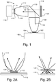
- Fig. 1 illustrates an illumination device 100 in accordance with one embodiment of the present invention.
- Fig. 1 includes a light source 102 that for the sake of simplicity is sometimes referred to herein as a light emitting device (LED) 102.
- the light source may be a semiconductor light emitting device, such as a light emitting diode or array of light emitting diodes, or other types of light sources that can produce short wavelength light, such as a Xenon lamp or Mercury lamp.
- the LED 102 may be a high radiance device, such as the type described in U.S. Serial No.
- illumination device 100 includes a wavelength converting element 112 that is physically separated from the LED 102.
- the LED 102 and the wavelength converting element 112 may be separated along the beam path by, e.g., air, gas or a vacuum.
- the length of the physical separation of the LED 102 and the wavelength converting element 112 may vary, but in one embodiment is greater than 1mm.
- the physical separation between the LED 102 and the wavelength converting element 112 is sufficient to prevent substantial conductive heating (ideally the separation is sufficient to prevent any conductive heating) of the wavelength converting element 112 by the LED 102.
- Wavelength converting element 112 may be, e.g., a conventionally produced layer of phosphor or other wavelength converting material in a binding medium, such as epoxy or silicone.
- the type and amount of phosphor used in wavelength converting element 112 is dependent on the factors such as the primary emission wavelength range of the LED 102 and the desired wavelengths of the converted light. It should be understood that LED 102 generally produces a primary emission that has a range of wavelengths. The range of wavelengths is generally narrow and, thus, LEDs are sometimes characterized by a single wavelength, which is the dominant or peak wavelength in the spectrum produced.
- wavelength converting element 112 may use phosphors such as: Thiogallate (TG), SrSiON:Eu, or SrBaSiO:Eu to produce converted light in the green spectrum; BaSrSiN:Eu to produce converted light in the amber spectrum; CaS:Eu, (Sr0.5,Ca0.5)S:Eu, SrS:Eu, and SrSiN:Eu to produce converted light in the red spectrum; and YAG to produce white converted light.
- TG Thiogallate
- SrSiON:Eu SrBaSiO:Eu
- BaSrSiN:Eu to produce converted light in the amber spectrum
- CaS:Eu, (Sr0.5,Ca0.5)S:Eu, SrS:Eu, and SrSiN:Eu to produce converted light in the red spectrum
- YAG to produce white converted light.
- the wavelength converting element is sometimes referred to herein as a phosphor element, but it
- the phosphor element 112 is shown mounted on a highly reflective substrate 115, such as an ESR specular reflecting film manufactured by 3M or E60L white diffuse reflecting film manufactured by Toray, and thermally coupled to a heatsink 116. It should be understood that, if desired, the LED 102 and phosphor element 112 may share the same heatsink if the heatsink is large enough to prevent significant conductive heating of the phosphor element 112. Because the phosphor element 112 is physically separated from the LED 102, the heat produced by LED 102 will have little or no affect on the operation of the phosphor element 112. Accordingly, the LED 102 can be driven with a high current to produce a high radiance.
- a highly reflective substrate 115 such as an ESR specular reflecting film manufactured by 3M or E60L white diffuse reflecting film manufactured by Toray
- heat from the phosphor element 112 caused by phosphor light conversion can be dissipated. Because heating of phosphor can degrade performance by approximately 20 to 30 percent, the use of a heatsink 116 can dramatically increase performance of the phosphor element 112.
- the color separation element 110 may be, e.g., a dichroic mirror, and for ease of reference, the color separation element will sometimes be referred to herein as a dichroic mirror. Nevertheless, it should be understood that other color separation elements may be used with the present invention, such as a dichroic cube, a diffractive optical element or a hologram.
- An adequate dichroic mirror may be purchased from, e.g., Unaxis Balzers Ltd. located in Liechtenstein or Optical Coating Laboratory, Inc. located in Santa Rosa, California.
- the color separation element 110 is used to prevent a substantial amount of the converted light emitted by phosphor element 112 from being incident on the LED 102. Ideally no converted light would be incident on the LED 102, however, color separation elements, such as dichroic mirrors are not ideal and may leak between 0 and 30 percent of the converted light. Accordingly, absorption of the converted light by LED 102 is reduced, thereby improving efficiency in conversion and recycling, and thus in the radiance of the illumination device 100.
- Optical elements are used to collimate the primary light and converted light prior to being incident on the dichroic mirror 110.
- a collimator 108 between the LED 102 and the dichroic mirror 110 is used to collimate the light emitted by LED 102.
- Another collimator 114 between the phosphor element 112 and the dichroic mirror 110 is used to collimate the converted light emitted by the phosphor element 112, and to focus the primary light reflected by the dichroic mirror 110 onto the phosphor element 112.
- the optical elements need not be collimators, but may be other optical elements, such as a reflective compound parabolic concentrator element, a total internal reflecting optical element, a rectangular reflective angle transformer, a condenser lens, a lens assembly, or a combination of such elements. Because color separation elements, such as dichroic mirrors, are angle dependent, the optical elements preferably produce a narrow light cone.
- the optical elements may have, e.g., a circular or rectangular geometry and may be conventionally formed of materials such as molded plastic or metal, such as aluminum, or metal alloys. If the LED 102 is driven at a high temperature, the use of a temperature insensitive material, such as metal or glass is particularly advantageous.
- the phosphor element 112 receives the primary light from the LED 102 and converts the primary light to another wavelength range by absorbing the primary light and emitting the converted light.
- Light from the LED 102 that is not absorbed by the phosphor element 112 is reflected by the reflective substrate 115 and reflected back to the LED 102 by the dichroic mirror 110, where the light is reflected back to the phosphor element 112.
- the non-absorbed primary light is at least partially recycled in illumination device 100.
- the reflective substrate 115 is used to reflect a portion of the converted light towards the dichroic mirror 110. The converted light is then transmitted by the dichroic mirror 110.
- the device 100 may include a radiance enhancement film 118.
- a radiance enhancement film may be, e.g., a diffractive optical element, such as that manufactured by Heptagon located in Zurich, Switzerland, or a micro refractive element or Brightness Enhancement Film, such as that manufactured by 3M.
- device 100 may include a polarization recovery component 120, sometimes referred to as a non-absorbing polarizer, such as that manufactured by Moxtek, Inc. located in Orem Utah, or by 3M known as a Dual Brightness Enhancement Film.
- the relative positions of the radiance enhancement film 118 and polarization recovery component 120 maybe reversed.
- the radiance enhancement film 118 and polarization recovery component 120 restrict the angular distribution and polarization state of the light produced by illumination device 100, by transmitting the desired light and reflecting the undesired light back towards the phosphor element 112. Because the phosphor element 112 has very little absorption of the light generated, the recycling efficiency is very high.
- Fig. 1 illustrates the LED 102 and phosphor element 112 oriented at 90 degrees with respect to each other
- other angles may be used.
- the color separation and efficiency of dichroic mirrors is angle dependent, it may be desirable for the LED 102 and phosphor element 112 to be oriented at less than 45 degrees with respect to each other.
- a radiance enhancement structure 122 (and/or polarization recovery component) may be mounted over the phosphor element 112.
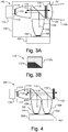
- Figs. 2A and 2B illustrate closer views of the operation of the phosphor element 112 with a radiance enhancement structure 122.
- the radiance enhancement structure 122 may be separated from the phosphor element 112 or may be in physical contact with the phosphor element 112.
- the radiance enhancement structure 122 is, e.g., a dichroic mirror or diffractive optical element.
- the dichroic mirror is designed such that the primary light emitted by the LED 102 is transmitted over a large range of incident angles, but that converted light emitted by the phosphor element 112 is transmitted over a limited range of incident angles, e.g., 30 degrees or less from the surface normal, as illustrated in Figs. 2A and 2B .
- the radiance enhancement structure 122 ensures that a large percentage of the light will be utilized downstream.
- Fig. 2B illustrates that converted light emitted by the phosphor element 112 at large angles will be reflected by the radiance enhancement structure 122 to be reabsorbed and reemitted by the phosphor element 112. Thus, part of the light will be emitted during a second pass, thereby increasing the radiance of the illumination device 100.
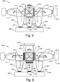
- Figs. 3A and 3B illustrate an illumination device 150 that is similar to device 100, like designated elements being the same.
- device 150 is adapted for use as an automobile headlight and includes an enclosure 152 for the components and a projection lens 154 that produces the resulting beam 156.
- a similar configuration may be used as a spot light if desired.
- the phosphor element 112' may be patterned with different types or amounts of phosphor to form, e.g., a standardized headlight beam pattern.
- a first portion 112'a of the phosphor element 112' may include a blend of yellow and blue phosphor, in which case the LED 102 emits a lower wavelength range, e.g., UV light.
- the first portion 112'a may use a yellow phosphor while the LED 102 emits blue light and the dichroic mirror 110 is partially transparent to blue light.
- the second portion 112'b of the phosphor element 112' may have less or no phosphor or a different blend of phosphor.
- the portion 112'b with little or no phosphor will convert less light than the portion 112'a.
- the dichroic mirror 110 will transmit the light converted by portion 112'a and will reflect most of the unconverted blue light from portion 112'b back towards the LED 102.
- the standardized beam pattern formed by portions 112'a and 112'b will be projected by the projection lens 154.
- Fig. 4 illustrates another embodiment of an illumination device 200, which is similar to device 100, like designated elements being the same.
- Illumination device 200 approximately doubles the radiance with respect to device 100 by using two LEDs 102 and 202.
- the second LED 202 is held on an optional submount 204 and may share a heatsink 206 with LED 102.
- the second LED 202 emits light that is collimated by collimator 208 and that is reflected towards the phosphor element 112 by a second color separation element, i.e., dichroic mirror 210.
- the light emitted by the second LED 202 has a different wavelength range than the light emitted by LED 102.
- the LEDs 102 and 202 may emit light with peak wavelengths that differ by approximately 20nm, e.g., approximately 430nm and 450nm or 400nm and 435nm.
- the phosphor element 112 should have a large absorption spectrum or a mixture of phosphors so that the primary light from LEDs 102 and 202 is converted.
- the device 200 has approximately twice the radiance of device 100.
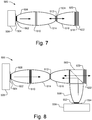
- Fig. 5 illustrates another embodiment of an illumination device 300 that includes a plurality of light sources and a plurality of remote wavelength converting elements.
- Device 300 may be used to produce combined red, green and blue light, which may be used in e.g., a color sequential projector, such as a Digital Light Processing (DLP) projector or a Liquid Crystal on Silicon (LCoS) projector. If desired, additional colors may be produced by device 300, such as cyan and amber.
- DLP Digital Light Processing
- LCDoS Liquid Crystal on Silicon
- Device 300 is similar in operation to device 100, like designated elements being the same. Device 300, however, includes additional LEDs 302 and 322 that are held on respective optional submounts 304 and 324. All the LEDs 102, 302, and 322 may share the same heatsink 306.
- Device 300 generates red and green light using remote phosphor elements 112 and 312, respectively, in the same manner as described above in reference to Fig. 1 .
- optical elements such as collimator 308, collimate the primary light, which may be blue or UV light, from LED 302 and dichroic mirror 310 reflects the light towards a second phosphor element 312.
- Collimator 314 focus the light on the phosphor element 312, which is held on a reflective mirror 315 and heatsink 316.
- Converted green light from phosphor element 312 is transmitted through dichroic mirror 310 and transmitted through (or reflected for recycling by) a radiance enhancement film 318 and polarization recovery component 320.
- Device 300 may directly produce blue light, e.g., using an LED 322 with a primary emission in the blue spectrum.
- optical elements such as collimator 328, collimate the blue emitted light, which is transmitted through (or reflected for recycling by) a radiance enhancement film 338 and polarization recovery component 340.
- the use of radiance enhancement films and polarization recovery components increase the radiance and polarization and makes the illumination of the device 300 more uniform.
- radiance enhancement films such as that described in reference to Fig. 2A and 2B may be located before the phosphor elements 112 and 312.
- device 300 may produce blue light in the same manner as described above in reference to Fig. 1 , i.e., using an LED with a primary emission in the UV spectrum and using a physically separated phosphor element that converts the primary emission into blue light.
- the necessary components i.e., color separation element, optical elements and phosphor element may extend into or out of the plane of Fig. 5 .
- the device 300 includes an X-plate 342, e.g., two dichroic mirrors in a crossed geometry, and a condenser lens 344 to combine the red, green and blue light. If desired, a single radiance enhancement film and polarization recovery component pair may be located between the X-plate 342 and the condenser lens 344 thereby obviating the need for three pairs of radiance enhancement films and polarization recovery components.
- device 300 may produce additional colors, e.g., amber and cyan, using additional LEDs and phosphor elements in the same manner as described in reference to Fig. 1 .
- additional LEDs, phosphor elements, and associated optical elements and dichroic mirrors may extend into or out of the plane of the page.
- Fig. 6 illustrates an illumination device 400 that is similar to device 300, like designated elements being the same.
- Device 400 is configured for a three panel LCD projection device, such as the type made by Epson (Japan).
- Device 400 includes an X-cube 402 in front of a projection lens 403.
- the X-cube 402 combines the red, green and blue images generated by microdisplays 404, 406, and 408, respectively, which are, e.g., High Temperature Poly Silicon (HTPS) LCD displays.
- HTPS High Temperature Poly Silicon
- Fig. 7 illustrates another embodiment of an illumination device 500.
- Device 500 has a linear arrangement of the light source and remote, i.e., physically separate, wavelength converting element, which is particularly advantageous for illumination devices with space limitations, such as a flash light.
- device 500 includes an LED 502 on an optional submount 504 and heat sink 506.
- a collimator 508, or other optical element, collimates the primary light emitted from LED 502, which is transmitted through dichroic mirror 510 towards phosphor element 512.
- a second collimator 514 focuses the primary light that is transmitted through the dichroic mirror 510 to the phosphor element 512.
- the phosphor element 512 absorbs the primary light emitted by LED 502 and emits light having longer wavelengths in both directions, i.e., towards and away from the dichroic mirror 510.
- the dichroic mirror 510 reflects converted light emitted by the phosphor element 512 back towards phosphor element 512.
- dichroic mirror 510 prevents converted light from being incident on the LED 502 thereby improving efficiency of the device 500.
- a portion of the converted light emitted from phosphor element 512 is collimated by collimator 516, or other appropriate optical element.
- a second dichroic mirror 518 transmits the converted light and reflects any unconverted light back towards the phosphor element 512.
- a radiance enhancement film 520 and polarization recovery component 522 may be located after the dichroic mirror 518 to recycle light that cannot be used downstream of the device 500. If desired, an additional radiance enhancement film 524 or polarization recovery component may be located on the phosphor element 512, e.g., as described in reference to Figs. 2A and 2B .
- Fig. 8 is another embodiment of an illumination device 550, which is similar to device 500, like designated elements being the same.
- Device 550 uses an additional light source so that the phosphor element 512 is illuminated from the front and back, thereby approximately doubling the radiance of the device.
- device 550 uses a second LED 552 (on an optional submount 554 and heatsink 556) and a collimator 558 as a second light source.
- a dichroic cube 560 or other appropriate device, such as a dichroic mirror, reflects light emitted by LED 552 towards the phosphor element 512 and transmits converted light from the phosphor element 512.
- the two LEDs 502 and 552 may emit primary light having the same wavelength ranges.
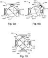
- Illumination device 600 advantageously combines the function of the optical elements and the dichroics using a dichroic sphere 610.
- device 600 includes an LED 602 held on an optional submount 604 and heatsink 606.
- a condenser lens 608, which is held close to or in contact with the LED 602, may be used in conjunction with a dichroic sphere 610 to image the LED 602 onto the phosphor element 612.
- the dichroic sphere 610 may be, e.g., a glass or plastic sphere with a dichroic film deposited in the center, similar to a dichroic cube.
- a condenser lens 614 may be held close to or in contact with the phosphor element 612, which is mounted on a reflective submount 616 and heatsink 618.
- the phosphor element 612 converts the light emitted from the LED 602 to light with longer wavelengths, which is transmitted through the dichroic sphere 610 to lens 620.
- the converted light is collimated or otherwise focused by lens 620.
- a radiance enhancement film 622 and polarization recovery component 624 may be disposed after or before the lens 620.
- Fig. 9B is another illustration of illumination device 600 with the dichroic sphere 610 operating at a more efficient angle.
- dichroics operate with better color separation and efficiency at smaller angles of incidence.
- Fig. 9B illustrates the LED 602 and phosphor element 612 are at an angle of approximately 45 degrees with respect to each other and, thus, the dichroic sphere 610 is at an angle of approximately 22.5 degrees with respect to each of the LED 602 and phosphor element 612.
- other angles may be used, e.g., less than approximately 22.5 degrees.
- Fig. 10 is another embodiment of an illumination device 650 that is similar to device 600 like designated elements being the same.
- Device 650 includes a second LED 652 on an optional submount 654 and heatsink 656, which is optically coupled to the dichroic sphere 660 through, e.g., a condenser lens 658.
- the LEDs 602 and 652 may emit light with different wavelengths.
- the dichroic sphere 660 includes two dichroic mirrors that are responsive to wavelengths emitted by LEDs 602 and 652.
- the phosphor element 612 may include a combination of phosphors for the different wavelengths of light.
- the phosphor element 612 may be at other angles, e.g., approximately 45 degrees or less, with respect to both LED 602 and LED 652 and, thus, the color separation element in dichroic sphere 610 may be at other angles, e.g., approximately 22.5 degrees or less, with respect to each of the LEDs 602 and 652 and the phosphor element 612.
- Fig. 11A illustrates another embodiment of an illumination device 700 that may be used, e.g., as a color sequential projector or a studio or theater light.
- Device 700 is similar to device 100 shown in Fig. 1 , like designated elements being the same.
- Device 700 uses a dichroic cube 710 instead of a dichroic mirror 110.
- the wavelength converting element in device 700 is phosphor covered disk 712, which has a highly reflective substrate.
- the disk 712 may have multiple colored sections, each having different types and/or amounts of phosphor.
- Fig. 11B illustrates a plan view of the disk 712, which three different sections of the disk 712 with different types of phosphors.
- the disk 712 is rotated by motor 714. As the disk 712 spins, the different sections of the disk 712, and thus, different phosphors, are illuminated thereby producing different colors. Spinning the disk 712, additionally, may be used to cool the phosphor and can be used to generate air flow for cooling the heatsink 106.
- the color emitted by the device 700 may be controlled by synchronizing the duty cycle of the LED 102 and the spinning of the disk.
- the disk 712 may be held rotated and stopped to illuminate a different portion of the disk 712 when a different color is desired.
- the disk 712 may include multi color phosphors or may contain sections with different messages or symbols, such as logos. The device 700 would thus project the message or symbol, which can then be changed by rotating the disk 712 to illuminate another phosphor message or symbol on the disk 712.
- Fig. 12 illustrates another embodiment of an illumination device 800 that may be used e.g., as backlighting for a liquid crystal display (LCD) panel.
- an LED is used to produce a blue backlight that is used in combination with a phosphor dot pattern consisting of red and green phosphor dots, which are aligned with LCD pixels representing the red and green image pixels, respectively, while the blue pixels are left blank or applied with a non-phosphor scattering material.
- the LED may produce UV light or near UV light wherein blue phosphor dots are used in conjunction with the red and green phosphor dots.
- an LED 802 on an optional submount 804 and heatsink 806, is used with a collimator 808 or other appropriate optical element.
- the LED 802 produces, e.g., blue or UV light.
- a wavelength converting element 812 which includes, e.g., red and green phosphor dots (and blue phosphor dots if the LED 802 produces UV light), is located at end of the collimator 808 opposite the LED 802.
- a dichroic mirror 810 is disposed between the LED 802 and the wavelength converting element 812, e.g., on the LED 802. The dichroic mirror 810 transmits the blue or UV light emitted by the LED 802 but reflects long wavelengths. Thus, substantially all light emitted by the wavelength converting element 812 towards the LED 802 will be reflected by the dichroic mirror 810 and will not be incident on the LED 802.
- a second dichroic mirror 814 is disposed between the wavelength converting element 812 and an LCD panel 816 and lens 818.
- the second dichroic mirror 814 may be configured with a plurality of dichroic elements, each dichroic element being aligned with a corresponding phosphor dot, e.g., red, green and blue dichroic elements are aligned with red, green and blue emitting phosphor dots, respectively.
- the second dichroic mirror 814 is configured to transmit light over a narrow range of angles and reflects light outside the range of angles back towards the wavelength converting element 812 and dichroic mirror 810.
- the pixels in the LCD panel 816 advantageously receive light at a narrow range of angles, thereby improving performance of the device.
- Fig. 13 illustrates an embodiment of a device 850 that includes a semiconductor light emitting device 852, a first dichroic element 854, a wavelength converting element 856, a polarizing element 858, and a second dichroic element 860.
- Some or all of the various elements shown in Fig. 13 may be separated, e.g., by an air gap.
- the various elements 852, 854, 856, 858, and 860 are separated from each other by 1mm or more.
- some or all of the elements shown in Fig. 13 may be in physical contact, i.e., with one element on top and physically contacting the next.
- the semiconductor light emitting device 852 emits light in the blue or UV wavelengths.
- the wavelength converting element 856 converts the light from the semiconductor light emitting device 852 to other wavelengths, e.g., red, green or blue.
- the first dichroic element 854 transmits light that is emitted by the semiconductor light emitting device 852 and reflects light emitted by the wavelength converting element 856.
- the polarizing element 858 which may be omitted if desired, serves a as a polarization recovery component and transmits one polarization state and reflects the other polarization states back to the wavelength converting element 856.
- the second dichroic element 860 serves as a radiance enhancement film by transmitting light emitted by the wavelength converting element 856 over a narrow range of angles, e.g., within 25 degrees from normal, and reflecting light that is outside the range of angles back towards the wavelength converting element 856.
- the second dichroic element 860 also reflects unconverted light from the semiconductor light emitting device 852 that leaked through the wavelength converting element 856 back to the wavelength converting element 856.
- the second dichroic element 860 separates light based on both color and angle of incidence.
- the light that exits the dichroic element 860 is, thus, converted light that is polarized and is within a narrow range of angles.
- an illumination device (100, 150, 200, 300, 400, 500, 550,600, 650, 800, 850) comprises a light source (102, 202, 302, 322, 502, 522, 602, 652, 802, 852) that emits light having a first wavelength range along a first beam path (103), a wavelength converting element (112, 112', 512, 612, 812, 856) in the first beam path, the wavelength converting element being physically separated from the light source, and the wavelength converting element converting the light having a first wavelength range into light having a second wavelength range along a second beam path (113); a color separation element (110, 210, 310, 510, 610, 810, 854) disposed between the light source and the wavelength converting element, the color separation element being configured to prevent substantially all of the light having the second wavelength range from being incident on the light source.
- the illumination device further comprises at least one of a radiance enhancement film (118, 318, 520, 622, 814) and a polarization recovery component (120, 320, 522, 624, 858) coupled to receive the light emitted from the wavelength converting element.
- a radiance enhancement film 118, 318, 520, 622, 81
- a polarization recovery component 120, 320, 522, 624, 858
- the light source is one of a semiconductor light emitting device, a Xenon lamp, and a Mercury lamp.
- the light source comprises one or more light emitting diodes.
- the radiance enhancement film comprises a dichroic mirror or diffractive optical element.
- the radiance enhancement film comprises at least one of a diffractive optical element and a micro refractive element and wherein the polarization recovery component comprises a non-absorbing polarizer.
- the wavelength converting element is a phosphor.
- the phosphor is patterned.
- the illumination device comprises a rotatable element, the rotatable element having at least a first section being covered with a first phosphor that converts the light having a first wavelength range to the light having the second wavelength range and a second section being covered with a second phosphor that converts the light having a first wavelength range to the light having a third wavelength range, wherein the color separation element is configured to further prevent substantially all of the light having the third wavelength range from being incident on the light source.
- the color separation element according to any of the first to eight further embodiments is selected from the group consisting of a dichroic mirror, a dichroic cube, a dichroic sphere, a diffractive optical element and a hologram.
- the wavelength converting element is mounted on a reflective submount (115, 315, 616).
- the illumination device according to any of the first to tenth further embodiments further comprising a lens (154, 620), wherein the color separation element reflects the light having a first wavelength range from the light source to the wavelength converting element and transmits the light having the second wavelength range from the wavelength converting element to the lens.
- the illumination device further comprises a first optical element (108, 208, 308, 328, 508, 808) disposed between the light source and the color separation element, the first optical element collimates the light emitted from the light source; and a second optical element (114, 314, 514) disposed between the wavelength converting element and the color separation element, the second optical element focuses the collimated light from the light source on the wavelength converting element and collimates the converted light having a second wavelength range.
- a first optical element 108, 208, 308, 328, 508, 808
- the first optical element and the second optical element each include at least one of a collimator, reflective compound parabolic concentrator element, total internal reflecting optical element, a rectangular reflective angle transformer, a condenser lens, and a lens assembly.
- he illumination device further comprise a second light source (202) that emits light having a third wavelength range along a third beam path; wherein the color separation element is a first color separation element (110) that is further disposed between the second light source and the wavelength converting element, the first color separation element configured to transmit substantially all of the light having the second wavelength range and the light having the third wavelength range and to reflect substantially all of the light having a first wavelength range; and a second color separation element (210) disposed between the second light source (202) and the first color separation element (110), the second color separation element being configured to transmit substantially all of the light having the second wavelength range and to reflect substantially all of the light having the third wavelength range; wherein the wavelength converting element is in the first beam path and the third beam path, the wavelength converting element converting both the light having the first wavelength range and the light having the third wavelength range into light having the second wavelength range.
- the color separation element is a first color separation element (110) that is further disposed between the second light source and the wavelength converting element, the first color separation element configured to transmit substantially
- the illumination device according to the fourteenth further embodiment further comprises a third optical element (208) disposed between the second light source and the second color separation element, the third optical element collimates the light emitted from the second light source.
- the illumination device comprises a second light source (302) that emits light having a third wavelength range along a third beam path; a second wavelength converting element 312) in the third beam path, the second wavelength converting element being physically separated from the second light source, the second wavelength converting element converting the light having the third wavelength range to light having a fourth wavelength range along a fourth beam path; and a second color separation element (310) disposed between the second light source and the second wavelength converting element, the second color separation element being configured to prevent substantially all of the light having the fourth wavelength range from the second wavelength converting element from being incident on the second light source; and a third color separation element (342) disposed between the wavelength converting element and the second wavelength converting element, the third color separation element being configured to combine the light having the second wavelength range and the light having the fourth wavelength range.
- the illumination device according to the sixteenth further embodiment further comprises a lens (344) disposed after the third color separation element.
- the illumination device according to the sixteenth or seventeenth further embodiment the third color separation element is one of an X-plate and an X-cube.
- the lens is a condenser lens.
- the illumination device according to the sixteenth, seventeenth, eighteenth or nineteenth further embodiment further comprises a third light source (322) that emits a light having a fifth wavelength range, wherein the third color separation element is further configured to combine the light having the second wavelength range, the light having the fourth wavelength range, and the light having the fifth wavelength range.
- a third light source 322 that emits a light having a fifth wavelength range
- the third color separation element is further configured to combine the light having the second wavelength range, the light having the fourth wavelength range, and the light having the fifth wavelength range.
- the illumination device further comprises a first of at least one of a radiance enhancement film (118) and a polarization recovery component (120) disposed between the color separation element (110) and the third color separation element (342); a second of at least one of a radiance enhancement film (318) and a polarization recovery component (320) disposed between the second color separation element (310) and the third color separation element (342); and a third of at least one of a radiance enhancement film (338) and a polarization recovery component (340) disposed between the third light source (322) and the third color separation element 342).
- the illumination device further comprises a first microdisplay (404) disposed between the first of at least one of a radiance enhancement film and a polarization recovery component and the third color separation element; a second microdisplay (406) disposed between the second of at least one of a radiance enhancement film and a polarization recovery component and the third color separation element; and a third microdisplay (408) disposed between the third of at least one of a radiance enhancement film and a polarization recovery component and the third color separation element; wherein the lens is a projector lens.
- the illumination device further comprises a third light source that emits light having a fifth wavelength range along a fifth beam path; a third wavelength converting element in the fifth beam path, the third wavelength converting element being physically separated from the third light source, the third wavelength converting element converting the light having the fifth wavelength range to light having a sixth wavelength range along a sixth beam path; and a fourth color separation element disposed between the third light source and the third wavelength converting element, the fourth color separation element being configured to prevent substantially all of the light having the sixth wavelength range from the third wavelength converting element from being incident on the third light source; wherein the third color separation element is further configured to combine the light having the second wavelength range, the light having the fourth wavelength range, and the light having the sixth wavelength range.
- the second wavelength range, fourth wavelength range and sixth wavelength range are in the red, green and blue spectra, respectively.
- the color separation element transmits the light having a first wavelength range from the light source to the wavelength converting element and reflects the light having the second wavelength range from the wavelength converting element back to the wavelength converting element.
- the illumination device further comprises a first optical element (508) disposed between the light source (502) and the color separation element (510), the first optical element collimates the light emitted from the light source; a second optical element (514) disposed between the wavelength converting element (512) and the color separation element (510), the second optical element focuses the collimated light from the light source on the wavelength converting element, wherein the color separation element is disposed between the first optical element and the second optical element; and a third optical element (516), wherein the wavelength converting element is disposed between the second optical element and the third optical element, the wavelength converting element emits light having the second wavelength range along the second beam path and along a third beam path that is in the opposite direction of the second beam path, the third optical element collimates the light having the second wavelength range along the third beam path and the second optical element collimates the light having the second wavelength range along the second beam path.
- a first optical element disposed between the light source (502) and the color separation element (510)
- a second optical element
- the first optical element, the second optical element, and the third optical element each include at least one of a collimator, reflective compound parabolic concentrator element, total internal reflecting optical element, a rectangular reflective angle transformer, a condenser lens, and a lens assembly.
- the illumination device according to the twenty-sixth or twenty-seventh further embodiment further comprises a second color separation element, the wavelength converting element being disposed between the second color separation element and second optical element, the second color separation element transmits light having the second wavelength range and reflects light having the first wavelength range back to the wavelength converting element.
- the illumination device further comprises a second light source (552) that emits light having a third wavelength range along a third beam path; a second color separation element (560) disposed between the second light source and the wavelength converting element (512), the second color separation element being configured to transmit substantially all of the light having the second wavelength range and to reflect substantially all of the light having the third wavelength range; a fourth optical element (558) disposed between the second light source and the second color separation element, the fourth optical element collimates the light emitted from the second light source; wherein the wavelength converting element is in the first beam path and the third beam path, the third optical element focuses the collimated light from the second light source onto the wavelength converting element, the wavelength converting element converts both the light having the first wavelength range and the light having the third wavelength range into light having the second wavelength range.
- a second light source 552 that emits light having a third wavelength range along a third beam path
- a second color separation element (560) disposed between the second light source and the wavelength converting element (512), the
- the first wavelength range and the third wavelength range are approximately the same wavelength range.
- the illumination device further comprises a second color separation element (122) disposed over the wavelength converting element, the second color separation element configured to transmit light having the first wavelength range over a first range of angles and to transmit light having the second wavelength range over a second range of angles, the second range of angles is smaller than the first range of angles, wherein the second color separation element reflects light having the second wavelength range outside the second range of angles back to the wavelength converting element.
- a second color separation element (122) disposed over the wavelength converting element, the second color separation element configured to transmit light having the first wavelength range over a first range of angles and to transmit light having the second wavelength range over a second range of angles, the second range of angles is smaller than the first range of angles, wherein the second color separation element reflects light having the second wavelength range outside the second range of angles back to the wavelength converting element.
- the second range of angles is approximately 30 degrees.
- the second color separation element is a dichroic mirror.
- the second color separation element is disposed in the beam path between the light source and the wavelength converting element.
- the wavelength converting element is disposed in the beam path between the light source and the second color separation element, the illumination device further comprising a third color separation element that transmits light having the second wavelength range and reflecting light having the first wavelength range, the second color separation element being disposed between the third color separation element and the wavelength converting element.
- the illumination device further comprises a second color separation element (814, 122) disposed over the wavelength converting element, the second color separation element configured to transmit light having the second wavelength range over a range of angles, wherein the second color separation element reflects light having the second wavelength range outside the range of angles back to the wavelength converting element.
- a second color separation element (814, 122) disposed over the wavelength converting element, the second color separation element configured to transmit light having the second wavelength range over a range of angles, wherein the second color separation element reflects light having the second wavelength range outside the range of angles back to the wavelength converting element.
- the wavelength converting element (812) comprises a plurality of phosphor dots
- the illumination device further comprising an LCD panel (816) wherein the second color separation element (814) is disposed between the wavelength converting element and the LCD panel.
- the illumination device further comprises an optical element (808) disposed between the light source and the wavelength converting element, the optical element collimates the light emitted from the light source; and a lens (818), the LCD panel being disposed between the second color separation element and the lens.
- the wavelength converting element is physically separated from the light source by more than one millimeter.
- the wavelength converting element is physically separated from the light source by one of air, gas, and vacuum.
- the wavelength converting element is physically separated from the light source sufficiently to prevent substantial conductive heating of the wavelength converting element by the light source.
- the illumination device further comprises a first optical element 108, 508) associated with the light source, the first optical element collimates the light emitted from the light source along the first beam path; the color separation element (110, 510) in the first beam path, the color separation element configured to direct substantially all of the collimated light along the first beam path toward a second optical element (114, 514), the second optical element focuses the collimated light; and the wavelength converting element (112, 512) receiving the focused light from the second optical element, the wavelength converting element configured to at least partially absorb light of the first wavelength range and to emit light having a second wavelength range, the second optical element collimates the light having the second wavelength range emitted by the wavelength converting element, wherein the color separation element prevents light having a second wavelength range from being incident on the light source.
- the light source is one of a semiconductor light emitting device, a Xenon lamp, and a Mercury lamp.
- the light source comprises one or more light emitting diodes.
- the color separation element reflects light having a first wavelength range and transmits light having a second wavelength range.
- the wavelength converting element is mounted on a reflective substrate (115).
- the reflective substrate is mounted on a heatsink (116).
- the color separation element transmits light having a first wavelength range and reflects light having a second wavelength range.
- the wavelength converting element is being disposed between the second optical element and the third optical element, the third optical element collimates light having a second wavelength range emitted by the wavelength converting element.
- the illumination device further comprises a second color separation element (560), the third optical element being disposed between the second color separation element and the wavelength converting element, the second color separation element transmits light having the second wavelength range and reflects light having the first wavelength range.
- the color separation element (110, 854) that receives light emitted by the light source is configured to direct substantially all of the light emitted by the light source toward the wavelength covering element (112, 112', 856); the wavelength converting element receives the light from the color separation element, the wavelength converting element is configured to at least partially absorb light of the first wavelength range and to emit light having a second wavelength range, wherein the color separation element prevents light having a second wavelength range from being incident on the light source; and the illumination device further comprising a second color separation element (122, 860) that receives light emitted by the wavelength converting element, the second color separation element is configured reflect light in the first wavelength range back to the wavelength converting element and to transmit light in the second wavelength range that is incident on the second color separation element in a first range of angles and to reflect light in the second wavelength range that is incident on the second color separation element outside the first range of angles.
- the light source is one of a semiconductor light emitting device, a Xenon lamp, and a Mercury lamp.
- the illumination device according to the fifty-first or fifty-second further embodiment comprises one or more light emitting diodes.
- the illumination device according to the fifty-first to fifty-third embodiment further comprises a polarization recovery component (120, 858), wherein the wavelength converting element is disposed between the polarization recover component and the light source.
- the light emitted by the light source having a first wavelength range is reflected by the color separation element (110) and light emitted by the wavelength converting element having a second wavelength range is transmitted through the first color separation element before being incident on the second color separation element (860).
- the illumination device further comprises a first optical element (108) disposed between the light source and the first color separation element, the first optical element collimates the light emitted from the light source; and a second optical element (114) disposed between the first color separation element and the wavelength converting element, the second optical element focuses the light from the first color separation element towards the wavelength converting element.
- the illumination device further comprises a third optical element disposed between the wavelength converting element and the second color separation element, the third optical element collimates the light emitted by the wavelength converting element.
- the light emitted by the light source having a first wavelength range is transmitted through the first color separation element and light emitted by the wavelength converting element having a second wavelength range is reflected by the first color separation element.
- the wavelength converting element is physically separated from the light source by one of air, gas, and vacuum.
Landscapes
- Physics & Mathematics (AREA)
- Optics & Photonics (AREA)
- General Physics & Mathematics (AREA)
- Multimedia (AREA)
- Engineering & Computer Science (AREA)
- Signal Processing (AREA)
- Non-Portable Lighting Devices Or Systems Thereof (AREA)
- Projection Apparatus (AREA)
- Led Device Packages (AREA)
- Arrangement Of Elements, Cooling, Sealing, Or The Like Of Lighting Devices (AREA)
- Securing Globes, Refractors, Reflectors Or The Like (AREA)
- Liquid Crystal (AREA)
- Diffracting Gratings Or Hologram Optical Elements (AREA)
Priority Applications (2)
| Application Number | Priority Date | Filing Date | Title |
|---|---|---|---|
| EP19201299.5A EP3621301B9 (fr) | 2004-06-04 | 2005-05-30 | Conversion de longueur d'onde à distance dans un dispositif d'éclairage |
| PL18167801T PL3383034T3 (pl) | 2004-06-04 | 2005-05-30 | Zdalna konwersja długości fali w urządzeniu oświetleniowym |
Applications Claiming Priority (2)
| Application Number | Priority Date | Filing Date | Title |
|---|---|---|---|
| US10/861,769 US7070300B2 (en) | 2004-06-04 | 2004-06-04 | Remote wavelength conversion in an illumination device |
| EP05104602.7A EP1605199B1 (fr) | 2004-06-04 | 2005-05-30 | Conversion de longueur d'onde à commande à distance pour dispositif d'illumination |
Related Parent Applications (2)
| Application Number | Title | Priority Date | Filing Date |
|---|---|---|---|
| EP05104602.7A Division EP1605199B1 (fr) | 2004-06-04 | 2005-05-30 | Conversion de longueur d'onde à commande à distance pour dispositif d'illumination |
| EP05104602.7A Division-Into EP1605199B1 (fr) | 2004-06-04 | 2005-05-30 | Conversion de longueur d'onde à commande à distance pour dispositif d'illumination |
Related Child Applications (2)
| Application Number | Title | Priority Date | Filing Date |
|---|---|---|---|
| EP19201299.5A Division EP3621301B9 (fr) | 2004-06-04 | 2005-05-30 | Conversion de longueur d'onde à distance dans un dispositif d'éclairage |
| EP19201299.5A Division-Into EP3621301B9 (fr) | 2004-06-04 | 2005-05-30 | Conversion de longueur d'onde à distance dans un dispositif d'éclairage |
Publications (2)
| Publication Number | Publication Date |
|---|---|
| EP3383034A1 true EP3383034A1 (fr) | 2018-10-03 |
| EP3383034B1 EP3383034B1 (fr) | 2019-11-06 |
Family
ID=35064478
Family Applications (3)
| Application Number | Title | Priority Date | Filing Date |
|---|---|---|---|
| EP19201299.5A Expired - Lifetime EP3621301B9 (fr) | 2004-06-04 | 2005-05-30 | Conversion de longueur d'onde à distance dans un dispositif d'éclairage |
| EP18167801.2A Expired - Lifetime EP3383034B1 (fr) | 2004-06-04 | 2005-05-30 | Conversion de longueur d'onde à distance dans un dispositif d'éclairage |
| EP05104602.7A Expired - Lifetime EP1605199B1 (fr) | 2004-06-04 | 2005-05-30 | Conversion de longueur d'onde à commande à distance pour dispositif d'illumination |
Family Applications Before (1)
| Application Number | Title | Priority Date | Filing Date |
|---|---|---|---|
| EP19201299.5A Expired - Lifetime EP3621301B9 (fr) | 2004-06-04 | 2005-05-30 | Conversion de longueur d'onde à distance dans un dispositif d'éclairage |
Family Applications After (1)
| Application Number | Title | Priority Date | Filing Date |
|---|---|---|---|
| EP05104602.7A Expired - Lifetime EP1605199B1 (fr) | 2004-06-04 | 2005-05-30 | Conversion de longueur d'onde à commande à distance pour dispositif d'illumination |
Country Status (6)
| Country | Link |
|---|---|
| US (1) | US7070300B2 (fr) |
| EP (3) | EP3621301B9 (fr) |
| JP (3) | JP4920907B2 (fr) |
| ES (2) | ES2877064T3 (fr) |
| PL (1) | PL3383034T3 (fr) |
| TW (1) | TWI343978B (fr) |
Families Citing this family (351)
| Publication number | Priority date | Publication date | Assignee | Title |
|---|---|---|---|---|
| US8075147B2 (en) * | 2003-05-13 | 2011-12-13 | Light Prescriptions Innovators, Llc | Optical device for LED-based lamp |
| JP2005316406A (ja) * | 2004-03-30 | 2005-11-10 | Sanyo Electric Co Ltd | 光学部材及び照明装置及び投写型映像表示装置 |
| US7724440B2 (en) * | 2004-04-23 | 2010-05-25 | Light Prescriptions Innovators, Llc | Combining outputs of different light sources |
| US7380962B2 (en) * | 2004-04-23 | 2008-06-03 | Light Prescriptions Innovators, Llc | Optical manifold for light-emitting diodes |
| WO2006035391A1 (fr) * | 2004-09-30 | 2006-04-06 | Koninklijke Philips Electronics N.V. | Amelioration de la brillance des del au moyen du recyclage angulaire selectif des rayons |
| KR100644632B1 (ko) * | 2004-10-01 | 2006-11-10 | 삼성전자주식회사 | Led를 채용한 조명유닛 및 이를 채용한 화상투사장치 |
| JP4691987B2 (ja) | 2004-12-28 | 2011-06-01 | 株式会社日立製作所 | 無線タグおよび携帯端末 |
| KR100683171B1 (ko) * | 2005-03-08 | 2007-02-15 | 삼성전자주식회사 | 방열장치 및 그것을 구비하는 프로젝터 |
| TW200634257A (en) * | 2005-03-24 | 2006-10-01 | Coretronic Corp | Illumination system |
| US7234820B2 (en) * | 2005-04-11 | 2007-06-26 | Philips Lumileds Lighting Company, Llc | Illuminators using reflective optics with recycling and color mixing |
| US7445340B2 (en) * | 2005-05-19 | 2008-11-04 | 3M Innovative Properties Company | Polarized, LED-based illumination source |
| US20060274284A1 (en) * | 2005-05-31 | 2006-12-07 | Infocus Corporation | Illumination arrangements for colored light sources |
| US8718437B2 (en) | 2006-03-07 | 2014-05-06 | Qd Vision, Inc. | Compositions, optical component, system including an optical component, devices, and other products |
| WO2007103310A2 (fr) | 2006-03-07 | 2007-09-13 | Qd Vision, Inc. | Objet contenant des nanocristaux semi-conducteurs |
| WO2006133214A2 (fr) * | 2005-06-07 | 2006-12-14 | Optical Research Associates | Illuminateur de disque fluorescent |
| JP5124978B2 (ja) | 2005-06-13 | 2013-01-23 | 日亜化学工業株式会社 | 発光装置 |
| US7543959B2 (en) * | 2005-10-11 | 2009-06-09 | Philips Lumiled Lighting Company, Llc | Illumination system with optical concentrator and wavelength converting element |
| KR101281342B1 (ko) * | 2005-11-22 | 2013-07-02 | 쓰리엠 이노베이티브 프로퍼티즈 컴파니 | 발광용품 어레이 및 이의 제조 방법 |
| WO2007070821A2 (fr) * | 2005-12-13 | 2007-06-21 | Ilight Technologies, Inc. | Dispositif d'eclairage avec transformation de la teinte |
| US7540616B2 (en) * | 2005-12-23 | 2009-06-02 | 3M Innovative Properties Company | Polarized, multicolor LED-based illumination source |
| WO2007081719A2 (fr) | 2006-01-05 | 2007-07-19 | Illumitex, Inc. | Dispositif optique séparé pour diriger de la lumière depuis une del |
| US20070165186A1 (en) * | 2006-01-13 | 2007-07-19 | Copner Nigel J | Light source system and an image projection system |
| US9874674B2 (en) | 2006-03-07 | 2018-01-23 | Samsung Electronics Co., Ltd. | Compositions, optical component, system including an optical component, devices, and other products |
| JP2007311114A (ja) * | 2006-05-17 | 2007-11-29 | Olympus Corp | 白色光を発する固体発光素子を用いた照明光学系、及びそれを備えた光学装置 |
| WO2007141688A1 (fr) * | 2006-06-02 | 2007-12-13 | Philips Intellectual Property & Standards Gmbh | dispositif d'éclairage générant une lumière colorée et une lumière blanche |
| US7663152B2 (en) * | 2006-08-09 | 2010-02-16 | Philips Lumileds Lighting Company, Llc | Illumination device including wavelength converting element side holding heat sink |
| DE102006045704A1 (de) * | 2006-09-27 | 2008-04-03 | Osram Opto Semiconductors Gmbh | Optisches Element und optoelektronisches Bauelement mit solch einem optischen Element |
| US8087960B2 (en) | 2006-10-02 | 2012-01-03 | Illumitex, Inc. | LED system and method |
| CN101536201A (zh) * | 2006-11-17 | 2009-09-16 | 3M创新有限公司 | 具有光学提取器的平面化发光二极管 |
| WO2008064070A1 (fr) * | 2006-11-17 | 2008-05-29 | 3M Innovative Properties Company | Composition de liaison optique pour source lumineuse à diodes électroluminescentes |
| JP4561732B2 (ja) * | 2006-11-20 | 2010-10-13 | トヨタ自動車株式会社 | 移動体位置測位装置 |
| JP2010510685A (ja) * | 2006-11-20 | 2010-04-02 | スリーエム イノベイティブ プロパティズ カンパニー | Led光源用の光学接着組成物 |
| US7905605B2 (en) * | 2006-12-13 | 2011-03-15 | Koninklijke Philips Electronics N.V. | Multi-primary LED projection system |
| US7902560B2 (en) * | 2006-12-15 | 2011-03-08 | Koninklijke Philips Electronics N.V. | Tunable white point light source using a wavelength converting element |
| KR20090096629A (ko) * | 2006-12-15 | 2009-09-11 | 코닌클리즈케 필립스 일렉트로닉스 엔.브이. | 2색 표면을 갖는 조명 시스템 |
| US7845822B2 (en) * | 2006-12-29 | 2010-12-07 | Koninklijke Philips Electronics N.V. | Illumination device including a color selecting panel for recycling unwanted light |
| US8836212B2 (en) | 2007-01-11 | 2014-09-16 | Qd Vision, Inc. | Light emissive printed article printed with quantum dot ink |
| US20080198572A1 (en) * | 2007-02-21 | 2008-08-21 | Medendorp Nicholas W | LED lighting systems including luminescent layers on remote reflectors |
| DE102007009820A1 (de) * | 2007-02-28 | 2008-09-04 | Osram Opto Semiconductors Gmbh | Optische Anordnung und optisches Verfahren |
| US8203260B2 (en) * | 2007-04-13 | 2012-06-19 | Intematix Corporation | Color temperature tunable white light source |
| CN101663769B (zh) * | 2007-04-17 | 2013-02-06 | 皇家飞利浦电子股份有限公司 | 照明系统 |
| US20080260328A1 (en) * | 2007-04-20 | 2008-10-23 | 3M Innovative Properties Company | Led light extraction bar and injection optic for thin lightguide |
| US20080260329A1 (en) * | 2007-04-20 | 2008-10-23 | 3M Innovative Properties Company | Lightguides having curved light injectors |
| US7703943B2 (en) * | 2007-05-07 | 2010-04-27 | Intematix Corporation | Color tunable light source |
| WO2008142638A1 (fr) * | 2007-05-24 | 2008-11-27 | Koninklijke Philips Electronics N.V. | Système d'éclairage à réglage de couleurs |
| US7744241B2 (en) * | 2007-06-13 | 2010-06-29 | Ylx, Ltd. | High brightness light source using light emitting devices of different wavelengths and wavelength conversion |
| WO2009014707A2 (fr) | 2007-07-23 | 2009-01-29 | Qd Vision, Inc. | Substrat d'amélioration de lumière à point quantique et dispositif d'éclairage le comprenant |
| WO2009013695A2 (fr) * | 2007-07-25 | 2009-01-29 | Koninklijke Philips Electronics N.V. | Dispositif de conversion de couleur et dispositif de sortie lumineuse à couleur réglable |
| US7547114B2 (en) * | 2007-07-30 | 2009-06-16 | Ylx Corp. | Multicolor illumination device using moving plate with wavelength conversion materials |
| US8128249B2 (en) | 2007-08-28 | 2012-03-06 | Qd Vision, Inc. | Apparatus for selectively backlighting a material |
| DE102008012316B4 (de) * | 2007-09-28 | 2023-02-02 | OSRAM Opto Semiconductors Gesellschaft mit beschränkter Haftung | Halbleiterlichtquelle mit einer Primärstrahlungsquelle und einem Lumineszenzkonversionselement |
| WO2009062053A1 (fr) * | 2007-11-08 | 2009-05-14 | Dialight Corporation | Système de mélange de couleur à led à double collimateur |
| WO2009066206A1 (fr) * | 2007-11-19 | 2009-05-28 | Koninklijke Philips Electronics N.V. | Source de lumière et système d'éclairage ayant une apparence externe prédéfinie |
| US20090153805A1 (en) * | 2007-12-14 | 2009-06-18 | Fu Zhun Precision Industry (Shen Zhen) Co., Ltd. | Portable projector with a heat dissipation system |
| US8147081B2 (en) * | 2007-12-26 | 2012-04-03 | Lumination Llc | Directional linear light source |
| TWI341376B (en) * | 2007-12-31 | 2011-05-01 | Ind Tech Res Inst | Illuminating apparatus of a polarization light |
| US8096668B2 (en) * | 2008-01-16 | 2012-01-17 | Abu-Ageel Nayef M | Illumination systems utilizing wavelength conversion materials |
| DE102008017071A1 (de) * | 2008-01-31 | 2009-08-06 | Osram Opto Semiconductors Gmbh | Optoelektronisches Modul und Projektionsvorrichtung mit dem optoelektronischen Modul |
| JP2011512037A (ja) | 2008-02-08 | 2011-04-14 | イルミテックス, インコーポレイテッド | エミッタ層成形のためのシステムおよび方法 |
| EP2250818A1 (fr) * | 2008-02-08 | 2010-11-17 | Koninklijke Philips Electronics N.V. | Dispositif de module lumineux |
| CN102016402A (zh) * | 2008-02-21 | 2011-04-13 | 光处方革新有限公司 | 球形发射远距离磷光体 |
| DE102008011866B4 (de) * | 2008-02-29 | 2018-05-03 | Osram Opto Semiconductors Gmbh | Lichtquellenanordnung mit einer Halbleiterlichtquelle |
| US8105322B2 (en) * | 2008-03-11 | 2012-01-31 | Shaser, Inc. | Replacement cartridges for light-based dermatologic treatment devices |
| WO2009115976A1 (fr) * | 2008-03-20 | 2009-09-24 | Koninklijke Philips Electronics N.V. | Système d'éclairage comprenant un élément luminescent avec un dissipateur thermique |
| US8116005B2 (en) * | 2008-04-04 | 2012-02-14 | Texas Instruments Incorporated | Light combiner |
| JP4662183B2 (ja) * | 2008-04-16 | 2011-03-30 | カシオ計算機株式会社 | 光源装置及びプロジェクタ |
| WO2009151515A1 (fr) | 2008-05-06 | 2009-12-17 | Qd Vision, Inc. | Dispositifs d'éclairage à semi-conducteurs comprenant des nanoparticules semi-conductrices confinées quantiques |
| WO2009137053A1 (fr) | 2008-05-06 | 2009-11-12 | Qd Vision, Inc. | Composants optiques, systèmes comprenant un composant optique et dispositifs associés |
| US9207385B2 (en) | 2008-05-06 | 2015-12-08 | Qd Vision, Inc. | Lighting systems and devices including same |
| US9354448B2 (en) | 2008-06-04 | 2016-05-31 | Koninklijke Philips N.V. | Lighting apparatus |
| US8410504B2 (en) * | 2008-06-10 | 2013-04-02 | Koninklijke Philips Electronics N.V. | LED module |
| DE102008030819A1 (de) | 2008-06-30 | 2009-12-31 | Osram Opto Semiconductors Gmbh | Optoelektronische Vorrichtung |
| JP5527571B2 (ja) * | 2008-09-30 | 2014-06-18 | カシオ計算機株式会社 | 発光装置及び光源装置並びにこの光源装置を用いたプロジェクタ |
| TW201034256A (en) | 2008-12-11 | 2010-09-16 | Illumitex Inc | Systems and methods for packaging light-emitting diode devices |
| WO2010084451A1 (fr) * | 2009-01-21 | 2010-07-29 | Koninklijke Philips Electronics N.V. | Source de lumière comprenant un dispositif de recyclage de lumière et dispositif de recyclage de lumière correspondant |
| EP2412038B1 (fr) * | 2009-03-19 | 2019-01-02 | Philips Lighting Holding B.V. | Dispositif d'éclairage avec matériau luminescent à distance |
| JP4900736B2 (ja) * | 2009-03-31 | 2012-03-21 | カシオ計算機株式会社 | 光源装置及びプロジェクタ |
| US8104907B2 (en) * | 2009-04-29 | 2012-01-31 | Koninklijke Philips Electronics N.V. | Remote wavelength converting material configuration for lighting |
| DE102009024941A1 (de) * | 2009-06-09 | 2010-12-23 | Carl Zeiss Surgical Gmbh | Beleuchtungsvorrichtung und medizinisch-optisches Beobachtungsgerät |
| JP4711021B2 (ja) * | 2009-06-30 | 2011-06-29 | カシオ計算機株式会社 | 投影装置 |
| JP5504747B2 (ja) * | 2009-08-20 | 2014-05-28 | セイコーエプソン株式会社 | プロジェクター |
| US8585253B2 (en) | 2009-08-20 | 2013-11-19 | Illumitex, Inc. | System and method for color mixing lens array |
| JP5581629B2 (ja) | 2009-08-20 | 2014-09-03 | セイコーエプソン株式会社 | プロジェクター |
| US8449128B2 (en) | 2009-08-20 | 2013-05-28 | Illumitex, Inc. | System and method for a lens and phosphor layer |
| JP5407664B2 (ja) * | 2009-08-27 | 2014-02-05 | セイコーエプソン株式会社 | プロジェクター |
| JP5333852B2 (ja) * | 2009-09-14 | 2013-11-06 | カシオ計算機株式会社 | プロジェクタ |
| JP5370764B2 (ja) * | 2009-09-15 | 2013-12-18 | カシオ計算機株式会社 | 光源装置及びプロジェクタ |
| KR101679063B1 (ko) * | 2009-09-16 | 2016-11-24 | 코닌클리케 필립스 엔.브이. | 사전정의된 각-색 좌표 분포를 갖는 발광 소자 |
| JP5796272B2 (ja) * | 2009-09-28 | 2015-10-21 | カシオ計算機株式会社 | 光源装置、投影装置及び投影方法 |
| US8591040B2 (en) | 2009-11-13 | 2013-11-26 | Prism Projection, Inc. | Projection device for architectural and entertainment lighting |
| JP2011108502A (ja) * | 2009-11-18 | 2011-06-02 | Stanley Electric Co Ltd | 光源装置および照明装置 |
| JP5507214B2 (ja) * | 2009-11-19 | 2014-05-28 | スタンレー電気株式会社 | 光源装置および照明装置 |
| JP2011124002A (ja) * | 2009-12-08 | 2011-06-23 | Stanley Electric Co Ltd | 光源装置および照明装置 |
| US8348430B2 (en) * | 2009-12-17 | 2013-01-08 | Alcon Research, Ltd. | Photonic lattice LEDs for ophthalmic illumination |
| JP5375581B2 (ja) * | 2009-12-17 | 2013-12-25 | セイコーエプソン株式会社 | 照明装置及びプロジェクター |
| JP5428078B2 (ja) * | 2009-12-21 | 2014-02-26 | カシオ計算機株式会社 | 光源装置及びプロジェクタ |
| JP5495023B2 (ja) * | 2009-12-21 | 2014-05-21 | カシオ計算機株式会社 | 光源ユニット及びプロジェクタ |
| US20110149592A1 (en) * | 2009-12-22 | 2011-06-23 | Artsyukhovich Alexander N | Light collector for a white light led illuminator |
| US20110148304A1 (en) * | 2009-12-22 | 2011-06-23 | Artsyukhovich Alexander N | Thermoelectric cooling for increased brightness in a white light l.e.d. illuminator |
| JP5428079B2 (ja) * | 2009-12-25 | 2014-02-26 | カシオ計算機株式会社 | 蛍光発光装置及びプロジェクタ |
| JP4991001B2 (ja) | 2009-12-28 | 2012-08-01 | シャープ株式会社 | 照明装置 |
| JP5618379B2 (ja) * | 2009-12-28 | 2014-11-05 | シャープ株式会社 | 照明装置 |
| US9022580B2 (en) * | 2010-01-29 | 2015-05-05 | Nec Display Solutions, Ltd. | Illumination optical system and projector using the same |
| EP3168684A1 (fr) * | 2010-01-29 | 2017-05-17 | NEC Display Solutions, Ltd. | Système optique d'éclairage et projecteur l'utilisant |
| JP5550368B2 (ja) * | 2010-02-03 | 2014-07-16 | スタンレー電気株式会社 | 光源装置および照明装置 |
| JP5423442B2 (ja) * | 2010-02-04 | 2014-02-19 | セイコーエプソン株式会社 | 照明装置及びプロジェクター |
| JP5491888B2 (ja) | 2010-02-05 | 2014-05-14 | 日立コンシューマエレクトロニクス株式会社 | 投写型表示装置 |
| GB2477569A (en) * | 2010-02-09 | 2011-08-10 | Sharp Kk | Lamp having a phosphor. |
| JP5671666B2 (ja) * | 2010-02-12 | 2015-02-18 | 日立マクセル株式会社 | 固体光源装置及び投射型表示装置 |
| DE102010001945B4 (de) | 2010-02-15 | 2019-07-25 | Osram Gmbh | Lichtquelleneinheit und Projektor mit einer derartigen Lichtquelleneinheit |
| DE102010001942B4 (de) | 2010-02-15 | 2012-03-29 | Osram Ag | Lichtquelleneinheit und Projektor mit einer derartigen Lichtquelleneinheit |
| US8646949B2 (en) * | 2010-03-03 | 2014-02-11 | LumenFlow Corp. | Constrained folded path resonant white light scintillator |
| JP5556256B2 (ja) * | 2010-03-11 | 2014-07-23 | パナソニック株式会社 | 照明装置および投写型画像表示装置 |
| US8384105B2 (en) | 2010-03-19 | 2013-02-26 | Micron Technology, Inc. | Light emitting diodes with enhanced thermal sinking and associated methods of operation |
| US9314374B2 (en) * | 2010-03-19 | 2016-04-19 | Alcon Research, Ltd. | Stroboscopic ophthalmic illuminator |
| EP2550686B1 (fr) * | 2010-03-22 | 2016-05-11 | Martin Professional ApS | Dispositif de projection comprenant plusieurs sources de lumière à stimulation mutuelle |
| JP5527594B2 (ja) * | 2010-03-24 | 2014-06-18 | カシオ計算機株式会社 | 光源ユニット及びプロジェクタ |
| JP5515941B2 (ja) * | 2010-03-26 | 2014-06-11 | セイコーエプソン株式会社 | プロジェクター |
| JP5445854B2 (ja) * | 2010-03-29 | 2014-03-19 | カシオ計算機株式会社 | 発光ユニット及びプロジェクタ |
| JP5539768B2 (ja) * | 2010-03-29 | 2014-07-02 | 京セラ株式会社 | 照明装置 |
| US8936377B2 (en) * | 2010-03-31 | 2015-01-20 | Alcon Research, Ltd. | Apparatus for enhancing brightness of a wavelength converting element |
| CN102213383B (zh) | 2010-04-01 | 2013-08-14 | 中强光电股份有限公司 | 光源模组与波长转换模组 |
| WO2011127286A1 (fr) * | 2010-04-07 | 2011-10-13 | Appotronics Corporation Limited | Dispositif d'éclairage à luminosité élevée utilisant une excitation double face de matériaux de conversion de longueur d'onde |
| WO2011127622A1 (fr) * | 2010-04-12 | 2011-10-20 | 绎立锐光科技开发(深圳)有限公司 | Procédé d'amplification de la couleur d'une lumière basé sur la conversion de longueur d'onde de la lumière |
| TWI438490B (zh) * | 2010-05-14 | 2014-05-21 | Delta Electronics Inc | 光源系統以及使用該光源系統之投影裝置 |
| JP5408756B2 (ja) * | 2010-05-21 | 2014-02-05 | Necディスプレイソリューションズ株式会社 | 照明光学系とこれを用いたプロジェクタ |
| JP5483505B2 (ja) * | 2010-05-21 | 2014-05-07 | Necディスプレイソリューションズ株式会社 | 照明光学系とこれを用いたプロジェクタ |
| JP5770433B2 (ja) | 2010-06-18 | 2015-08-26 | ソニー株式会社 | 光源装置及び画像投影装置 |
| US9033530B2 (en) * | 2010-06-22 | 2015-05-19 | Osram Gmbh | Phosphor device and lighting apparatus comprising the same |
| WO2011160693A1 (fr) * | 2010-06-24 | 2011-12-29 | Osram Ag | Unité à source de lumière comprenant un élément luminophore |
| JP2012013898A (ja) * | 2010-06-30 | 2012-01-19 | Jvc Kenwood Corp | 光源装置および投射型表示装置 |
| JP5429079B2 (ja) * | 2010-06-30 | 2014-02-26 | 株式会社Jvcケンウッド | 光源装置および投射型表示装置 |
| EP2407826A1 (fr) * | 2010-07-08 | 2012-01-18 | Koninklijke Philips Electronics N.V. | Système de projection avec source de lumière semi-conducteur et matériau luminescent |
| EP2407825A1 (fr) | 2010-07-08 | 2012-01-18 | Koninklijke Philips Electronics N.V. | Système de projection avec source de lumière semi-conducteur et matériau luminescent |
| US8941135B2 (en) | 2010-07-15 | 2015-01-27 | Nitto Denko Corporation | Light emissive ceramic laminate and method of making same |
| JP5474698B2 (ja) * | 2010-07-29 | 2014-04-16 | 三洋電機株式会社 | 光源装置及び投写型映像表示装置 |
| JP5257420B2 (ja) * | 2010-08-04 | 2013-08-07 | ウシオ電機株式会社 | 光源装置 |
| JP5573473B2 (ja) * | 2010-08-06 | 2014-08-20 | セイコーエプソン株式会社 | 光源装置及びプロジェクター |
| CN102375314B (zh) * | 2010-08-09 | 2013-12-04 | 台达电子工业股份有限公司 | 光源系统及其适用的投影机 |
| DE102010034054A1 (de) * | 2010-08-11 | 2012-02-16 | Schott Ag | Laserbasierte Weißlichtquelle |
| KR20130099951A (ko) | 2010-08-20 | 2013-09-06 | 리서치 트라이앵글 인스티튜트, 인터내셔널 | 칼러 튜닝 가능 조명 장치 및 조명 장치들의 칼러 출력 튜닝 방법 |
| US9101036B2 (en) | 2010-08-20 | 2015-08-04 | Research Triangle Institute | Photoluminescent nanofiber composites, methods for fabrication, and related lighting devices |
| US9441811B2 (en) | 2010-08-20 | 2016-09-13 | Research Triangle Institute | Lighting devices utilizing optical waveguides and remote light converters, and related methods |
| CN103068301A (zh) * | 2010-08-24 | 2013-04-24 | 欧司朗有限公司 | 荧光装置以及包括其的照明设备 |
| WO2012025144A1 (fr) | 2010-08-24 | 2012-03-01 | Osram Ag | Dispositif luminescent et appareil d'éclairage comprenant celui-ci |
| CN103080633A (zh) * | 2010-08-26 | 2013-05-01 | 日本电气硝子株式会社 | 波长变换元件、光源和液晶用背光单元 |
| JP5601092B2 (ja) | 2010-08-27 | 2014-10-08 | セイコーエプソン株式会社 | 照明装置及びプロジェクター |
| WO2012030764A2 (fr) * | 2010-08-30 | 2012-03-08 | Neolac, Inc. | Préparation de lait maternel |
| US8573801B2 (en) | 2010-08-30 | 2013-11-05 | Alcon Research, Ltd. | LED illuminator |
| TWI425295B (zh) | 2010-09-28 | 2014-02-01 | 台達電子工業股份有限公司 | 光源系統與投影裝置 |
| CN102445827B (zh) * | 2010-09-30 | 2014-08-20 | 台达电子工业股份有限公司 | 光源系统与投影装置 |
| US8664624B2 (en) | 2010-09-30 | 2014-03-04 | Performance Indicator Llc | Illumination delivery system for generating sustained secondary emission |
| WO2012044887A1 (fr) | 2010-09-30 | 2012-04-05 | Performance Indicator, Llc. | Structure multicouches stable aux plans photolytique et environnemental permettant une conversion d'énergie à haute efficacité et une émission secondaire prolongée |
| JP2012079989A (ja) * | 2010-10-05 | 2012-04-19 | Stanley Electric Co Ltd | 光源装置および照明装置 |
| US9140429B2 (en) | 2010-10-14 | 2015-09-22 | Cree, Inc. | Optical element edge treatment for lighting device |
| US8455882B2 (en) * | 2010-10-15 | 2013-06-04 | Cree, Inc. | High efficiency LEDs |
| CN102455512B (zh) | 2010-10-21 | 2014-03-12 | 中强光电股份有限公司 | 照明装置及投影装置 |
| JP2012108486A (ja) * | 2010-10-21 | 2012-06-07 | Panasonic Corp | 光源装置および画像表示装置 |
| JP5336564B2 (ja) * | 2010-10-29 | 2013-11-06 | シャープ株式会社 | 発光装置、照明装置、車両用前照灯および車両 |
| JP5487077B2 (ja) * | 2010-10-29 | 2014-05-07 | シャープ株式会社 | 発光装置、車両用前照灯および照明装置 |
| JP5255040B2 (ja) * | 2010-10-29 | 2013-08-07 | シャープ株式会社 | 発光装置、車両用前照灯、照明装置および車両、ならびに、発光装置の組立方法 |
| TWI421620B (zh) | 2010-11-03 | 2014-01-01 | Delta Electronics Inc | 光源調整裝置及包含該光源調整裝置之投影系統 |
| US9648673B2 (en) | 2010-11-05 | 2017-05-09 | Cree, Inc. | Lighting device with spatially segregated primary and secondary emitters |
| US8491140B2 (en) | 2010-11-05 | 2013-07-23 | Cree, Inc. | Lighting device with multiple emitters and remote lumiphor |
| WO2012063322A1 (fr) * | 2010-11-09 | 2012-05-18 | Necディスプレイソリューションズ株式会社 | Dispositif d'éclairage et dispositif d'affichage du type à projection l'utilisant |
| JP5606634B2 (ja) * | 2010-11-09 | 2014-10-15 | オスラム ゲーエムベーハー | 蛍光要素と光学システムとを伴う蛍光アセンブリ、蛍光アセンブリを備えた光源ユニット、蛍光アセンブリを用いて光を変換するための方法、および、蛍光アセンブリまたは光源ユニットの使用 |
| CN102466956B (zh) * | 2010-11-11 | 2014-05-28 | 台达电子工业股份有限公司 | 光源调整装置及包含该光源调整装置的投影系统 |
| WO2012066654A1 (fr) * | 2010-11-17 | 2012-05-24 | Necディスプレイソリューションズ株式会社 | Appareil de source de lumière, appareil d'éclairage et appareil d'affichage du type à projection |
| JP5695887B2 (ja) * | 2010-11-18 | 2015-04-08 | スタンレー電気株式会社 | 光源装置および照明装置 |
| JP5629559B2 (ja) * | 2010-11-19 | 2014-11-19 | スタンレー電気株式会社 | 光源装置および照明装置 |
| JP5895226B2 (ja) * | 2010-11-30 | 2016-03-30 | パナソニックIpマネジメント株式会社 | 光源装置および投写型表示装置 |
| JP2012119193A (ja) | 2010-12-01 | 2012-06-21 | Sharp Corp | 発光装置、車両用前照灯、照明装置、及び車両 |
| DE102010062463A1 (de) * | 2010-12-06 | 2012-06-06 | Osram Ag | Leuchtvorrichtung |
| US9631792B2 (en) | 2010-12-08 | 2017-04-25 | Appotronics China Corporation | Light source system employing wavelength conversion materials and color filters |
| WO2012077021A1 (fr) * | 2010-12-09 | 2012-06-14 | Koninklijke Philips Electronics N.V. | Appareil d'éclairage permettant de générer de la lumière |
| EP2466375B1 (fr) * | 2010-12-17 | 2019-12-25 | Maxell, Ltd. | Appareil de source lumineuse |
| US8657476B2 (en) | 2010-12-22 | 2014-02-25 | Energy Focus, Inc. | Elongated LED lighting arrangement |
| WO2012091971A1 (fr) | 2010-12-29 | 2012-07-05 | 3M Innovative Properties Company | Constructions de led à phosphore distant |
| WO2012091973A1 (fr) * | 2010-12-29 | 2012-07-05 | 3M Innovative Properties Company | Dispositif à diodes électroluminescentes à substance luminescente distant doté d'un flux lumineux à large bande et d'une couleur contrôlable |
| US20120154917A1 (en) * | 2011-01-18 | 2012-06-21 | Eric William Hearn Teather | Color-shifting reflector |
| TWI432780B (zh) | 2011-01-19 | 2014-04-01 | 台達電子工業股份有限公司 | 光源系統 |
| DE102011002961A1 (de) * | 2011-01-21 | 2012-07-26 | Osram Ag | Leuchtstoffvorrichtung mit Innenkühlung und Reflektorleuchtenanordnung mit dieser Leuchtstoffvorrichtung |
| JP5780153B2 (ja) * | 2011-01-24 | 2015-09-16 | 株式会社Jvcケンウッド | 光源装置及び投射型表示装置 |
| JP5759198B2 (ja) * | 2011-02-10 | 2015-08-05 | セイコーエプソン株式会社 | 発光素子、光源装置及びプロジェクター |
| US20120209358A1 (en) * | 2011-02-15 | 2012-08-16 | Feng Xiao-Fan | Color adaptive therapeutic light control system |
| DE102011004563B4 (de) | 2011-02-23 | 2014-02-20 | Osram Gmbh | Optikelement und Leuchtvorrichtung |
| DE112011104985T5 (de) * | 2011-03-01 | 2014-01-16 | Osram Gmbh | Beleuchtungsvorrichtung mit Leuchtstoffelement |
| JP5788194B2 (ja) | 2011-03-03 | 2015-09-30 | シャープ株式会社 | 発光装置、照明装置、及び車両用前照灯 |
| JP5656290B2 (ja) * | 2011-03-18 | 2015-01-21 | スタンレー電気株式会社 | 半導体発光装置 |
| EP2687903B1 (fr) * | 2011-03-18 | 2018-11-28 | Nec Display Solutions, Ltd | Système optique d'éclairage équipé de phosphore et projecteur |
| TWI427397B (zh) * | 2011-03-23 | 2014-02-21 | 台達電子工業股份有限公司 | 光源系統 |
| JP5348163B2 (ja) * | 2011-03-23 | 2013-11-20 | カシオ計算機株式会社 | 光源装置及びプロジェクタ |
| JP5223941B2 (ja) * | 2011-03-28 | 2013-06-26 | カシオ計算機株式会社 | 投影装置 |
| JP5783406B2 (ja) * | 2011-03-31 | 2015-09-24 | カシオ計算機株式会社 | 光源装置、及びプロジェクタ |
| JP5331156B2 (ja) * | 2011-04-28 | 2013-10-30 | シャープ株式会社 | 投光ユニットおよび投光装置 |
| WO2012154431A2 (fr) * | 2011-05-12 | 2012-11-15 | 3M Innovative Properties Company | Phosphore converti à distance au moyen de led |
| WO2012154433A2 (fr) * | 2011-05-12 | 2012-11-15 | 3M Innovative Properties Company | Convertisseur de polarisation de phosphore à distance |
| WO2012154446A1 (fr) * | 2011-05-12 | 2012-11-15 | 3M Innovative Properties Company | Structure optique pour del à luminophore distante |
| JP5870259B2 (ja) * | 2011-05-25 | 2016-02-24 | パナソニックIpマネジメント株式会社 | 照明装置および該照明装置を備える投射型表示装置 |
| DE102011080179A1 (de) * | 2011-08-01 | 2013-02-07 | Osram Ag | Wellenlängenkonversionskörper und Verfahren zu dessen Herstellung |
| GB201114084D0 (en) * | 2011-08-16 | 2011-09-28 | Eis Optics Ltd | Optical wheel |
| GB201114495D0 (en) * | 2011-08-23 | 2011-10-05 | Cymtec Ltd | Radiation generating apparatus and a method of generating radiation |
| US9612511B2 (en) * | 2011-08-25 | 2017-04-04 | Appotronics Corporation Limited | Projection system using excitable wavelength conversion material in the light source |
| CN105549311B (zh) * | 2011-08-27 | 2018-11-13 | 深圳市光峰光电技术有限公司 | 投影系统及其发光装置 |
| US9075299B2 (en) * | 2011-08-27 | 2015-07-07 | Appotronics Corporation Limited | Light source with wavelength conversion device and filter plate |
| JP2013047736A (ja) * | 2011-08-29 | 2013-03-07 | Mitsubishi Electric Corp | 光源装置および投写型表示装置 |
| JP5804536B2 (ja) * | 2011-09-13 | 2015-11-04 | Necディスプレイソリューションズ株式会社 | 照明光学系および投写型表示装置 |
| US8919993B2 (en) * | 2011-09-17 | 2014-12-30 | Appotronics Corporation Limited | High recycling efficiency solid state light source device |
| JP5252053B2 (ja) * | 2011-09-20 | 2013-07-31 | カシオ計算機株式会社 | 光源ユニット及びプロジェクタ |
| US10310363B2 (en) | 2011-09-22 | 2019-06-04 | Delta Electronics, Inc. | Phosphor device with spectrum of converted light comprising at least a color light |
| US10688527B2 (en) | 2011-09-22 | 2020-06-23 | Delta Electronics, Inc. | Phosphor device comprising plural phosphor agents for converting waveband light into plural color lights with different wavelength peaks |
| TWI448806B (zh) | 2011-09-22 | 2014-08-11 | Delta Electronics Inc | 螢光劑裝置及其所適用之光源系統及投影設備 |
| US9134595B2 (en) * | 2011-09-29 | 2015-09-15 | Casio Computer Co., Ltd. | Phosphor device, illumination apparatus and projector apparatus |
| CN103034035A (zh) * | 2011-09-30 | 2013-04-10 | 中强光电股份有限公司 | 照明系统与投影装置 |
| JP5834723B2 (ja) * | 2011-09-30 | 2015-12-24 | カシオ計算機株式会社 | 光源装置及びプロジェクタ装置 |
| KR20130036472A (ko) * | 2011-10-04 | 2013-04-12 | 엘지전자 주식회사 | 파장 변환층을 포함하는 디스플레이 장치 |
| TWM426048U (en) | 2011-10-07 | 2012-04-01 | Benq Corp | Light source module and projector using the same |
| US20140347842A1 (en) * | 2011-10-07 | 2014-11-27 | Cymtec Ltd | Radiation generating apparatus and a method of generating radiation |
| US9195123B2 (en) | 2011-10-13 | 2015-11-24 | Texas Instruments Corporated | Projector light source and system, including configuration for display of 3D images |
| US9816683B2 (en) * | 2011-10-20 | 2017-11-14 | Appotronics Corporation Limited | Light sources system and projection device using the same |
| US9442357B2 (en) | 2011-10-25 | 2016-09-13 | Texas Instruments Incorporated | Spectral filtering of phosphor color wheels |
| CN102393598B (zh) * | 2011-11-03 | 2014-03-26 | 海信集团有限公司 | 光源装置及应用其的投影机 |
| CN102520570B (zh) | 2011-12-04 | 2015-05-27 | 深圳市光峰光电技术有限公司 | 发光装置及其应用的投影系统 |
| DE102011088791B3 (de) * | 2011-12-16 | 2013-04-11 | Osram Gmbh | Beleuchtungseinheit mit einem Leuchtstoffelement, Beleuchtungsvorrichtung und Verwendung davon |
| CN102722073B (zh) * | 2011-12-18 | 2014-12-31 | 深圳市光峰光电技术有限公司 | 光源系统及投影装置 |
| DE102012101663B4 (de) | 2012-02-29 | 2019-12-24 | Osram Opto Semiconductors Gmbh | Konversionselement, Leuchtmittel und Verfahren zur Herstellung eines Konversionselements |
| JP5660074B2 (ja) * | 2012-04-20 | 2015-01-28 | カシオ計算機株式会社 | 光源装置及びプロジェクタ |
| US9239133B2 (en) | 2012-05-24 | 2016-01-19 | Excelitas Canada, Inc. | High brightness solid state illumination system for fluorescence imaging and analysis |
| US9952442B2 (en) | 2012-05-24 | 2018-04-24 | Excelitas Canada, Inc. | High brightness solid state illumination system for fluorescence imaging and analysis |
| JP6019762B2 (ja) * | 2012-05-30 | 2016-11-02 | 日亜化学工業株式会社 | 光源装置及びこの光源装置を備えたプロジェクタ |
| JP2013254889A (ja) * | 2012-06-08 | 2013-12-19 | Idec Corp | 光源装置および照明装置 |
| US9810942B2 (en) * | 2012-06-15 | 2017-11-07 | Apple Inc. | Quantum dot-enhanced display having dichroic filter |
| US8870428B2 (en) | 2012-06-20 | 2014-10-28 | Energy Focus, Inc. | Elongated LED lighting arrangement |
| JP2014010181A (ja) * | 2012-06-27 | 2014-01-20 | Ricoh Co Ltd | 光源装置及び投射装置 |
| JP5959342B2 (ja) * | 2012-07-09 | 2016-08-02 | オリンパス株式会社 | 光源装置 |
| JP2014017344A (ja) * | 2012-07-09 | 2014-01-30 | Olympus Corp | 光源装置 |
| GB201213053D0 (en) | 2012-07-23 | 2012-09-05 | Eis Optics Ltd | Compact light engine |
| JP5906986B2 (ja) * | 2012-07-31 | 2016-04-20 | セイコーエプソン株式会社 | 照明装置、電子機器及び投射型表示装置 |
| CN104932186B (zh) * | 2012-07-31 | 2017-04-05 | 深圳市绎立锐光科技开发有限公司 | 发光装置及相关投影系统 |
| US9388947B2 (en) * | 2012-08-28 | 2016-07-12 | Cree, Inc. | Lighting device including spatially segregated lumiphor and reflector arrangement |
| CN103838068B (zh) * | 2012-11-23 | 2016-12-28 | 深圳市光峰光电技术有限公司 | 发光装置及其相关投影系统 |
| JP5516709B2 (ja) * | 2012-12-07 | 2014-06-11 | カシオ計算機株式会社 | 光源装置及びプロジェクタ |
| JP2014119471A (ja) | 2012-12-13 | 2014-06-30 | Seiko Epson Corp | 光源装置及びプロジェクター |
| JP5648676B2 (ja) * | 2012-12-28 | 2015-01-07 | ウシオ電機株式会社 | 光源装置 |
| US9618737B2 (en) | 2013-01-29 | 2017-04-11 | Texas Instruments Incorporated | Color sequence illumination system with phosphor light filter |
| WO2014119783A1 (fr) | 2013-02-04 | 2014-08-07 | ウシオ電機株式会社 | Dispositif de source de lumière fluorescente |
| US9565782B2 (en) | 2013-02-15 | 2017-02-07 | Ecosense Lighting Inc. | Field replaceable power supply cartridge |
| US9108566B2 (en) | 2013-03-14 | 2015-08-18 | Federal-Mogul Corporation | Multi-pattern headlamp assembly and system |
| US9587790B2 (en) | 2013-03-15 | 2017-03-07 | Cree, Inc. | Remote lumiphor solid state lighting devices with enhanced light extraction |
| JP6232818B2 (ja) * | 2013-03-15 | 2017-11-22 | セイコーエプソン株式会社 | 照明装置及びプロジェクター |
| US9620933B1 (en) * | 2013-04-06 | 2017-04-11 | TeraDiode, Inc. | High brightness, monolithic, multispectral semiconductor laser |
| WO2014171135A1 (fr) * | 2013-04-18 | 2014-10-23 | パナソニック株式会社 | Dispositif d'affichage d'image de type à projection |
| CN103268039B (zh) | 2013-05-13 | 2015-12-09 | 北京京东方光电科技有限公司 | 一种背光模组及显示装置 |
| US10788678B2 (en) | 2013-05-17 | 2020-09-29 | Excelitas Canada, Inc. | High brightness solid state illumination system for fluorescence imaging and analysis |
| CN106195924B (zh) * | 2013-06-08 | 2019-05-03 | 深圳光峰科技股份有限公司 | 一种波长转换装置及其制作方法、相关发光装置 |
| US9039250B2 (en) * | 2013-08-05 | 2015-05-26 | Kaper Industrial Limited | Reflector assembly for eliminating unwanted stray lights |
| US9797573B2 (en) | 2013-08-09 | 2017-10-24 | Performance Indicator, Llc | Luminous systems |
| JP6205579B2 (ja) * | 2013-08-19 | 2017-10-04 | パナソニックIpマネジメント株式会社 | 光源装置および投写型映像表示装置 |
| JP5655911B2 (ja) * | 2013-08-21 | 2015-01-21 | カシオ計算機株式会社 | 光源装置及びプロジェクタ |
| US9863595B2 (en) | 2013-08-28 | 2018-01-09 | Sharp Kabushiki Kaisha | Light-emitting unit with optical plate reflecting excitation light and transmitting fluorescent light, and light-emitting device, illumination device, and vehicle headlight including the unit |
| JP6258083B2 (ja) * | 2013-08-28 | 2018-01-10 | シャープ株式会社 | 発光ユニット、発光装置、照明装置および車両用前照灯 |
| DE102013224691A1 (de) | 2013-12-02 | 2015-06-03 | Osram Gmbh | Beleuchtungsvorrichtung zur Erzeugung von Licht mittels Wellenlängenkonversion |
| JP5772935B2 (ja) * | 2013-12-13 | 2015-09-02 | セイコーエプソン株式会社 | プロジェクター |
| JP5709225B2 (ja) * | 2013-12-20 | 2015-04-30 | Necディスプレイソリューションズ株式会社 | 照明光学系とこれを用いたプロジェクタ |
| JP5783272B2 (ja) * | 2014-01-06 | 2015-09-24 | カシオ計算機株式会社 | 発光ユニット及びプロジェクタ |
| JP5780325B2 (ja) * | 2014-02-26 | 2015-09-16 | カシオ計算機株式会社 | 光源装置及びプロジェクタ |
| JP5790815B2 (ja) * | 2014-03-13 | 2015-10-07 | セイコーエプソン株式会社 | プロジェクター |
| TWI561773B (en) * | 2014-08-06 | 2016-12-11 | Delta Electronics Inc | Six-primary solid state illuminator and operating method using the same |
| JP2017535031A (ja) * | 2014-09-22 | 2017-11-24 | フィリップス ライティング ホールディング ビー ヴィ | 多段照明デバイス |
| CN105527787B (zh) * | 2014-09-29 | 2020-08-25 | 深圳光峰科技股份有限公司 | 发光装置、光源系统和投影系统 |
| CN105527788B (zh) * | 2014-09-29 | 2020-12-15 | 深圳光峰科技股份有限公司 | 发光系统及投影显示装置 |
| TWI513938B (zh) * | 2014-10-01 | 2015-12-21 | 錼創科技股份有限公司 | 光學模組 |
| JP5929995B2 (ja) * | 2014-10-01 | 2016-06-08 | カシオ計算機株式会社 | 回転体および投影装置 |
| CN104298060A (zh) * | 2014-10-15 | 2015-01-21 | 郭振扬 | 光源组件、光源装置以及发光方法 |
| JP5930001B2 (ja) * | 2014-10-23 | 2016-06-08 | カシオ計算機株式会社 | 投影装置 |
| CN204176387U (zh) | 2014-10-29 | 2015-02-25 | 深圳市绎立锐光科技开发有限公司 | 光源装置 |
| DE102014116737A1 (de) * | 2014-11-17 | 2016-05-19 | Karl Storz Gmbh & Co. Kg | Lichtquelleneinrichtung für endoskopische oder exoskopische Anwendungen |
| JP2016099558A (ja) * | 2014-11-25 | 2016-05-30 | セイコーエプソン株式会社 | 波長変換素子、光源装置、プロジェクターおよび波長変換素子の製造方法 |
| TWI571694B (zh) * | 2014-11-26 | 2017-02-21 | 中強光電股份有限公司 | 照明系統與投影裝置 |
| CN107208853B (zh) * | 2015-01-27 | 2019-11-15 | 飞利浦照明控股有限公司 | 高强度白光源 |
| DE102015101330A1 (de) | 2015-01-29 | 2016-08-04 | Osram Opto Semiconductors Gmbh | Vorrichtung zur Konversion der Wellenlänge einer elektromagnetischen Strahlung |
| US10378726B2 (en) | 2015-02-09 | 2019-08-13 | Ecosense Lighting Inc. | Lighting system generating a partially collimated distribution comprising a bowl reflector, a funnel reflector with two parabolic curves and an optically transparent body disposed between the funnel reflector and bowl reflector |
| US9869450B2 (en) | 2015-02-09 | 2018-01-16 | Ecosense Lighting Inc. | Lighting systems having a truncated parabolic- or hyperbolic-conical light reflector, or a total internal reflection lens; and having another light reflector |
| US10801696B2 (en) | 2015-02-09 | 2020-10-13 | Ecosense Lighting Inc. | Lighting systems generating partially-collimated light emissions |
| US11306897B2 (en) | 2015-02-09 | 2022-04-19 | Ecosense Lighting Inc. | Lighting systems generating partially-collimated light emissions |
| US9568665B2 (en) | 2015-03-03 | 2017-02-14 | Ecosense Lighting Inc. | Lighting systems including lens modules for selectable light distribution |
| US9651216B2 (en) | 2015-03-03 | 2017-05-16 | Ecosense Lighting Inc. | Lighting systems including asymmetric lens modules for selectable light distribution |
| US9746159B1 (en) | 2015-03-03 | 2017-08-29 | Ecosense Lighting Inc. | Lighting system having a sealing system |
| US9651227B2 (en) | 2015-03-03 | 2017-05-16 | Ecosense Lighting Inc. | Low-profile lighting system having pivotable lighting enclosure |
| US9726348B2 (en) | 2015-03-05 | 2017-08-08 | Christie Digital Systems Usa, Inc. | Wavelength conversion material array |
| DE102015103210A1 (de) * | 2015-03-05 | 2016-10-20 | Hella Kgaa Hueck & Co. | Beleuchtungsvorrichtung für Fahrzeuge |
| RU2721996C2 (ru) * | 2015-04-01 | 2020-05-25 | Филипс Лайтинг Холдинг Б.В. | Светоизлучающее устройство высокой яркости |
| CN108235720B (zh) * | 2015-05-26 | 2020-08-11 | 亮锐控股有限公司 | 用于产生高亮度光的光学设备 |
| USD785218S1 (en) | 2015-07-06 | 2017-04-25 | Ecosense Lighting Inc. | LED luminaire having a mounting system |
| EP3320569A4 (fr) | 2015-07-08 | 2019-02-13 | Performance Indicator, LLC | Système d'éclairage à panneau à del |
| USD782093S1 (en) | 2015-07-20 | 2017-03-21 | Ecosense Lighting Inc. | LED luminaire having a mounting system |
| USD782094S1 (en) | 2015-07-20 | 2017-03-21 | Ecosense Lighting Inc. | LED luminaire having a mounting system |
| US9651232B1 (en) | 2015-08-03 | 2017-05-16 | Ecosense Lighting Inc. | Lighting system having a mounting device |
| WO2017032655A1 (fr) * | 2015-08-24 | 2017-03-02 | Lumileds Holding B.V. | Dispositif d'éclairage pour phare de véhicule |
| CN106523955B (zh) | 2015-09-14 | 2019-10-11 | 中强光电股份有限公司 | 照明系统及投影装置 |
| DE102015115495A1 (de) * | 2015-09-15 | 2017-03-16 | Osram Opto Semiconductors Gmbh | Anordnung mit optoelektronischen Bauelementen, mit einem Konversionselement |
| CN105425523A (zh) * | 2015-12-29 | 2016-03-23 | 海信集团有限公司 | 一种激光光源和激光投影设备 |
| US10698150B2 (en) * | 2016-03-15 | 2020-06-30 | Signify Holding B.V. | Compound parabolic collimator array for high intensity lighting |
| CN109075161B (zh) * | 2016-04-29 | 2023-02-21 | 亮锐控股有限公司 | 高亮度绚白led光源 |
| US10133164B2 (en) * | 2016-05-25 | 2018-11-20 | Panasonic Intellectual Property Management Co., Ltd. | Projection display apparatus for improving the chromaticity of blue light |
| US20170371234A1 (en) * | 2016-06-28 | 2017-12-28 | Seiko Epson Corporation | Wavelength conversion device, lighting device, and projector |
| US11172560B2 (en) | 2016-08-25 | 2021-11-09 | Alcon Inc. | Ophthalmic illumination system with controlled chromaticity |
| EP3306392B1 (fr) * | 2016-10-06 | 2021-05-05 | Coretronic Corporation | Système d'éclairage et appareil de projection |
| TWI753894B (zh) * | 2017-03-31 | 2022-02-01 | 揚明光學股份有限公司 | 照明系統及投影裝置 |
| JP6888381B2 (ja) * | 2017-04-06 | 2021-06-16 | セイコーエプソン株式会社 | 光源装置及びプロジェクター |
| CN110637248A (zh) * | 2017-04-20 | 2019-12-31 | 德州仪器公司 | 具有固态照明光源的空间光调制图像显示投影仪设备 |
| TWI622835B (zh) * | 2017-06-01 | 2018-05-01 | 台達電子工業股份有限公司 | 背光模組及顯示裝置 |
| CN108983488B (zh) | 2017-06-01 | 2021-04-20 | 台达电子工业股份有限公司 | 背光模块及显示设备 |
| DE102017211726A1 (de) * | 2017-07-10 | 2019-01-10 | Zumtobel Lighting Gmbh | Optisches Element zur Beeinflussung eines, von einer LED-Lichtquelle abgestrahlten Lichts, Anordnung zur Lichtabgabe mit einem solchen optischen Element, sowie Phosphor-LED |
| JP2019040154A (ja) | 2017-08-29 | 2019-03-14 | セイコーエプソン株式会社 | 波長変換素子、波長変換光学系、光源装置、およびプロジェクター |
| JP7344202B2 (ja) | 2017-11-14 | 2023-09-13 | シグニファイ ホールディング ビー ヴィ | カラーホイールと共に使用される場合にデジタルスポークを可能にする固体光源 |
| JP2019145439A (ja) * | 2018-02-23 | 2019-08-29 | シャープ株式会社 | 光源装置、照明機器およびプロジェクタ装置 |
| CN108459409B (zh) * | 2018-06-14 | 2024-06-07 | 上海安翰医疗技术有限公司 | 照明设备及具有该照明设备的内窥镜 |
| WO2020044870A1 (fr) * | 2018-08-28 | 2020-03-05 | パナソニックIpマネジメント株式会社 | Élément de conversion de couleur |
| US20220082225A1 (en) * | 2018-10-05 | 2022-03-17 | Optonomous Technologies, Inc. | Laser phosphor light source for intelligent headlights and spotlights |
| DE102018126113A1 (de) * | 2018-10-19 | 2020-04-23 | Osram Opto Semiconductors Gmbh | Farbige Leuchtzelle für bildgebende Einheit mit Primärfarbenauswahl dank oszillierendem Bauteil |
| CN111142324A (zh) * | 2018-11-05 | 2020-05-12 | 扬明光学股份有限公司 | 固定式波长转换装置及应用其的投影机 |
| CN111413841B (zh) * | 2019-01-04 | 2023-08-11 | 深圳光峰科技股份有限公司 | 波长转换装置、光源系统与显示设备 |
| JP7389316B2 (ja) * | 2019-04-25 | 2023-11-30 | 日亜化学工業株式会社 | 発光装置 |
| US20220221129A1 (en) * | 2019-05-09 | 2022-07-14 | Signify Holding B.V. | Improved thermal management in laser-based lighting using a truncated ball lens |
| JP7292119B2 (ja) * | 2019-06-13 | 2023-06-16 | スタンレー電気株式会社 | 車両用前照灯 |
| WO2021063878A1 (fr) * | 2019-10-01 | 2021-04-08 | Signify Holding B.V. | Source de lumière laser blanche accordable en couleur à haute intensité utilisant du phosphore vert |
| DE102019126999A1 (de) * | 2019-10-08 | 2021-04-08 | Bayerische Motoren Werke Aktiengesellschaft | Beleuchtungsvorrichtung für ein Kraftfahrzeug |
| US12554185B2 (en) | 2020-02-05 | 2026-02-17 | Maxell, Ltd. | Cooled light source apparatus and projection type image display apparatus with noise-reducing fan system |
| DE112021002204A5 (de) * | 2020-04-08 | 2023-01-19 | Ams-Osram International Gmbh | Halbleiterbauelement und Verfahren zur Herstellung eines Halbleiterbauelements |
| US20230155058A1 (en) * | 2020-04-08 | 2023-05-18 | Ams-Osram International Gmbh | Optoelectronic Component |
| DE102020122282A1 (de) * | 2020-08-26 | 2022-03-03 | Hoya Corporation | Beleuchtungssystem |
| WO2022096271A1 (fr) | 2020-11-03 | 2022-05-12 | Signify Holding B.V. | Dispositif d'éclairage au phosphore laser réalisant la mise en forme du faisceau en utilisant des fibres concentriques |
| DE102020131178A1 (de) | 2020-11-25 | 2022-05-25 | Jenoptik Optical Systems Gmbh | Vorrichtung und Verfahren zum Erzeugen von Licht |
| US12181147B2 (en) * | 2020-12-01 | 2024-12-31 | Signify Holding, B.V. | Laser-based lighting device |
| JP2022116640A (ja) * | 2021-01-29 | 2022-08-10 | 京セラ株式会社 | 光接続構造及び照明システム |
| DE102021106766A1 (de) * | 2021-03-19 | 2022-09-22 | Precitec Optronik Gmbh | Chromatisch-konfokales Messsystem für Hochgeschwindigkeits-Abstandsmessung |
| WO2022207568A1 (fr) | 2021-04-01 | 2022-10-06 | Signify Holding B.V. | Source de lumière à diode superluminescente convertie au phosphore |
| US12538394B2 (en) | 2021-12-27 | 2026-01-27 | Signify Holding B.V. | High intensity BBL dimmable light source |
| JP7727879B1 (ja) | 2022-08-04 | 2025-08-21 | シグニファイ ホールディング ビー ヴィ | Cct制御による高輝度レーザ蛍光体照明 |
| CN120604074A (zh) | 2023-01-10 | 2025-09-05 | 昕诺飞控股有限公司 | 寿命增加的激光器-磷光体光源 |
| EP4684158A1 (fr) | 2023-03-21 | 2026-01-28 | Signify Holding B.V. | Empilement de bancs laser avec des trous pour obtenir une source de lumière blanche à haute luminosité |
| CN121569142A (zh) | 2023-07-13 | 2026-02-24 | 昕诺飞控股有限公司 | 在透射和反射模式中使用磷光体的激光磷光体光源 |
| WO2025162764A1 (fr) | 2024-01-30 | 2025-08-07 | Signify Holding B.V. | Moteur d'éclairage laser phosphore accordable à combinaison de faisceaux |
| WO2025162827A1 (fr) * | 2024-02-01 | 2025-08-07 | Signify Holding B.V. | Source de lumière blanche au laser-phosphore comprenant une lumière laser bleue diffusée, une lumière luag filtrée verte, une lumière yag filtrée rouge, et procédé de commande ctt |
| WO2025186028A1 (fr) | 2024-03-05 | 2025-09-12 | Signify Holding B.V. | Luminophore statique et luminophore dynamique pour produire une lumière à haute intensité et irc élevé |
| US20250324020A1 (en) * | 2024-04-15 | 2025-10-16 | GM Global Technology Operations LLC | Full color holographic projector with variable virtual image distance using single coherent light source |
| WO2025257117A1 (fr) | 2024-06-13 | 2025-12-18 | Signify Holding B.V. | Nouvelle configuration d'éclairage laser inoffensif pour l'œil utilisant un diffuseur de dépolarisation |
| WO2026012867A1 (fr) | 2024-07-11 | 2026-01-15 | Signify Holding B.V. | Source de lumière à base de laser compacte et efficace |
| WO2026061865A1 (fr) | 2024-09-19 | 2026-03-26 | Signify Holding B.V. | Moteur laser-phosphore accordable ayant un canal bleu spectralement amélioré |
| WO2026068266A1 (fr) | 2024-09-30 | 2026-04-02 | Signify Holding B.V. | Moteur laser au phosphore à trois sources bleues |
Citations (3)
| Publication number | Priority date | Publication date | Assignee | Title |
|---|---|---|---|---|
| JP2004071357A (ja) * | 2002-08-06 | 2004-03-04 | Shigeo Fujita | 照明装置 |
| WO2004021461A2 (fr) * | 2002-08-30 | 2004-03-11 | Gelcore Llc | Del recouverte a efficacite amelioree |
| US20040145913A1 (en) * | 2003-01-27 | 2004-07-29 | 3M Innovative Properties Company | Phosphor based light sources having a polymeric long pass reflector |
Family Cites Families (27)
| Publication number | Priority date | Publication date | Assignee | Title |
|---|---|---|---|---|
| JPS5913136A (ja) * | 1982-07-12 | 1984-01-23 | Nissan Motor Co Ltd | フリ−ホイ−ル用電磁クラツチ装置 |
| JP2698603B2 (ja) * | 1988-04-27 | 1998-01-19 | 株式会社マックサイエンス | 放射線画像読取装置 |
| US5897201A (en) | 1993-01-21 | 1999-04-27 | Simon; Jerome H. | Architectural lighting distributed from contained radially collimated light |
| US5504661A (en) | 1994-07-05 | 1996-04-02 | Ford Motor Company | Translucent fluorescent filter for display panels |
| US6582103B1 (en) | 1996-12-12 | 2003-06-24 | Teledyne Lighting And Display Products, Inc. | Lighting apparatus |
| JPH10197799A (ja) * | 1997-01-08 | 1998-07-31 | Olympus Optical Co Ltd | 光軸ずれ補正装置及び走査型光学顕微鏡 |
| US5813752A (en) | 1997-05-27 | 1998-09-29 | Philips Electronics North America Corporation | UV/blue LED-phosphor device with short wave pass, long wave pass band pass and peroit filters |
| US5813753A (en) | 1997-05-27 | 1998-09-29 | Philips Electronics North America Corporation | UV/blue led-phosphor device with efficient conversion of UV/blues light to visible light |
| JPH1123842A (ja) * | 1997-07-03 | 1999-01-29 | Minolta Co Ltd | 偏光ビームスプリッタ、該偏光ビームスプリッタを有する照明光学系およびプロジェクタ |
| US5982092A (en) | 1997-10-06 | 1999-11-09 | Chen; Hsing | Light Emitting Diode planar light source with blue light or ultraviolet ray-emitting luminescent crystal with optional UV filter |
| US6068383A (en) * | 1998-03-02 | 2000-05-30 | Robertson; Roger | Phosphorous fluorescent light assembly excited by light emitting diodes |
| US6273589B1 (en) | 1999-01-29 | 2001-08-14 | Agilent Technologies, Inc. | Solid state illumination source utilizing dichroic reflectors |
| US6504301B1 (en) | 1999-09-03 | 2003-01-07 | Lumileds Lighting, U.S., Llc | Non-incandescent lightbulb package using light emitting diodes |
| US6696703B2 (en) | 1999-09-27 | 2004-02-24 | Lumileds Lighting U.S., Llc | Thin film phosphor-converted light emitting diode device |
| US6350041B1 (en) * | 1999-12-03 | 2002-02-26 | Cree Lighting Company | High output radial dispersing lamp using a solid state light source |
| DE60135889D1 (de) * | 2000-03-17 | 2008-11-06 | Hitachi Ltd | Bildanzeigevorrichtung |
| JP2001264880A (ja) * | 2000-03-23 | 2001-09-26 | Sanyo Electric Co Ltd | 投写型表示装置 |
| US6604301B1 (en) * | 2000-07-10 | 2003-08-12 | II Arthur Manoli | Shoe sole insert |
| ES2351206T3 (es) | 2001-02-27 | 2011-02-01 | Dolby Laboratories Licensing Corporation | Dispositivo de visualización de alta relación de contraste dinámico. |
| GB0107076D0 (en) | 2001-03-21 | 2001-05-09 | Screen Technology Ltd | Liquid-crystal display using emissive elements |
| US6844903B2 (en) | 2001-04-04 | 2005-01-18 | Lumileds Lighting U.S., Llc | Blue backlight and phosphor layer for a color LCD |
| EP1306717A1 (fr) * | 2001-10-24 | 2003-05-02 | Rolic AG | Filtre de couleur commutable |
| US7153015B2 (en) * | 2001-12-31 | 2006-12-26 | Innovations In Optics, Inc. | Led white light optical system |
| JP2003217015A (ja) * | 2002-01-28 | 2003-07-31 | Fuji Electric Co Ltd | 商品見本展示装置および商品見本 |
| JP2004021206A (ja) * | 2002-06-20 | 2004-01-22 | Olympus Corp | 光源調整装置 |
| JP4829470B2 (ja) * | 2003-05-14 | 2011-12-07 | Necディスプレイソリューションズ株式会社 | 投写型表示装置 |
| US6869206B2 (en) | 2003-05-23 | 2005-03-22 | Scott Moore Zimmerman | Illumination systems utilizing highly reflective light emitting diodes and light recycling to enhance brightness |
-
2004
- 2004-06-04 US US10/861,769 patent/US7070300B2/en not_active Expired - Lifetime
-
2005
- 2005-05-30 EP EP19201299.5A patent/EP3621301B9/fr not_active Expired - Lifetime
- 2005-05-30 EP EP18167801.2A patent/EP3383034B1/fr not_active Expired - Lifetime
- 2005-05-30 PL PL18167801T patent/PL3383034T3/pl unknown
- 2005-05-30 EP EP05104602.7A patent/EP1605199B1/fr not_active Expired - Lifetime
- 2005-05-30 ES ES19201299T patent/ES2877064T3/es not_active Expired - Lifetime
- 2005-05-30 ES ES18167801T patent/ES2766198T3/es not_active Expired - Lifetime
- 2005-06-01 TW TW094118040A patent/TWI343978B/zh not_active IP Right Cessation
- 2005-06-01 JP JP2005161004A patent/JP4920907B2/ja not_active Expired - Lifetime
-
2011
- 2011-08-08 JP JP2011172691A patent/JP5450525B2/ja not_active Expired - Lifetime
-
2013
- 2013-05-17 JP JP2013104897A patent/JP5647295B2/ja not_active Expired - Lifetime
Patent Citations (3)
| Publication number | Priority date | Publication date | Assignee | Title |
|---|---|---|---|---|
| JP2004071357A (ja) * | 2002-08-06 | 2004-03-04 | Shigeo Fujita | 照明装置 |
| WO2004021461A2 (fr) * | 2002-08-30 | 2004-03-11 | Gelcore Llc | Del recouverte a efficacite amelioree |
| US20040145913A1 (en) * | 2003-01-27 | 2004-07-29 | 3M Innovative Properties Company | Phosphor based light sources having a polymeric long pass reflector |
Also Published As
| Publication number | Publication date |
|---|---|
| PL3383034T3 (pl) | 2020-07-27 |
| EP3621301A1 (fr) | 2020-03-11 |
| EP3621301B1 (fr) | 2021-04-21 |
| EP1605199A2 (fr) | 2005-12-14 |
| TWI343978B (en) | 2011-06-21 |
| JP2005347263A (ja) | 2005-12-15 |
| EP1605199B1 (fr) | 2018-07-11 |
| EP3621301B9 (fr) | 2021-08-18 |
| EP3383034B1 (fr) | 2019-11-06 |
| EP1605199A3 (fr) | 2011-01-26 |
| ES2766198T3 (es) | 2020-06-12 |
| JP5647295B2 (ja) | 2014-12-24 |
| TW200604466A (en) | 2006-02-01 |
| JP2013165073A (ja) | 2013-08-22 |
| US20050270775A1 (en) | 2005-12-08 |
| ES2877064T3 (es) | 2021-11-16 |
| JP4920907B2 (ja) | 2012-04-18 |
| JP5450525B2 (ja) | 2014-03-26 |
| US7070300B2 (en) | 2006-07-04 |
| JP2011243586A (ja) | 2011-12-01 |
Similar Documents
| Publication | Publication Date | Title |
|---|---|---|
| EP3383034A1 (fr) | Conversion de longueur d'onde à distance dans un dispositif d'éclairage | |
| US10852630B2 (en) | Illumination device and image display apparatus | |
| US9249949B2 (en) | Lighting device and projection-type display device using the same including a color-combining prism | |
| CN102346366B (zh) | 投影机 | |
| CN102385232B (zh) | 照明装置及投影机 | |
| US10136111B2 (en) | Wavelength converter, illuminator, and projector | |
| JP7142205B2 (ja) | 蛍光板、光源装置、及び投写型映像表示装置 | |
| US20160147136A1 (en) | Wavelength conversion element, light source device, projector, and method for manufacturing wavelength conversion element | |
| CN110308609B (zh) | 波长转换元件、波长转换元件制造方法、照明装置和投影仪 | |
| US10914453B2 (en) | Wavelength conversion device, illumination device, and projector | |
| KR20110044295A (ko) | 하나 이상의 광원을 구비한 광파이프를 사용하여 휘도를 증가시키기 위한 리사이클링 시스템 및 방법, 및 이를 포함하는 프로젝터 | |
| JPWO2018055903A1 (ja) | 光源装置および投射型表示装置 |
Legal Events
| Date | Code | Title | Description |
|---|---|---|---|
| PUAI | Public reference made under article 153(3) epc to a published international application that has entered the european phase |
Free format text: ORIGINAL CODE: 0009012 |
|
| STAA | Information on the status of an ep patent application or granted ep patent |
Free format text: STATUS: THE APPLICATION HAS BEEN PUBLISHED |
|
| AC | Divisional application: reference to earlier application |
Ref document number: 1605199 Country of ref document: EP Kind code of ref document: P |
|
| AK | Designated contracting states |
Kind code of ref document: A1 Designated state(s): AT BE BG CH CY CZ DE DK EE ES FI FR GB GR HU IE IS IT LI LT LU MC NL PL PT RO SE SI SK TR |
|
| RAP1 | Party data changed (applicant data changed or rights of an application transferred) |
Owner name: SIGNIFY NORTH AMERICA CORPORATION |
|
| STAA | Information on the status of an ep patent application or granted ep patent |
Free format text: STATUS: REQUEST FOR EXAMINATION WAS MADE |
|
| 17P | Request for examination filed |
Effective date: 20190403 |
|
| RBV | Designated contracting states (corrected) |
Designated state(s): AT BE BG CH CY CZ DE DK EE ES FI FR GB GR HU IE IS IT LI LT LU MC NL PL PT RO SE SI SK TR |
|
| GRAP | Despatch of communication of intention to grant a patent |
Free format text: ORIGINAL CODE: EPIDOSNIGR1 |
|
| STAA | Information on the status of an ep patent application or granted ep patent |
Free format text: STATUS: GRANT OF PATENT IS INTENDED |
|
| INTG | Intention to grant announced |
Effective date: 20190527 |
|
| GRAS | Grant fee paid |
Free format text: ORIGINAL CODE: EPIDOSNIGR3 |
|
| GRAA | (expected) grant |
Free format text: ORIGINAL CODE: 0009210 |
|
| STAA | Information on the status of an ep patent application or granted ep patent |
Free format text: STATUS: THE PATENT HAS BEEN GRANTED |
|
| AC | Divisional application: reference to earlier application |
Ref document number: 1605199 Country of ref document: EP Kind code of ref document: P |
|
| AK | Designated contracting states |
Kind code of ref document: B1 Designated state(s): AT BE BG CH CY CZ DE DK EE ES FI FR GB GR HU IE IS IT LI LT LU MC NL PL PT RO SE SI SK TR |
|
| REG | Reference to a national code |
Ref country code: GB Ref legal event code: FG4D |
|
| REG | Reference to a national code |
Ref country code: CH Ref legal event code: EP Ref country code: AT Ref legal event code: REF Ref document number: 1200466 Country of ref document: AT Kind code of ref document: T Effective date: 20191115 |
|
| REG | Reference to a national code |
Ref country code: DE Ref legal event code: R096 Ref document number: 602005056404 Country of ref document: DE |
|
| REG | Reference to a national code |
Ref country code: IE Ref legal event code: FG4D |
|
| REG | Reference to a national code |
Ref country code: NL Ref legal event code: MP Effective date: 20191106 |
|
| REG | Reference to a national code |
Ref country code: LT Ref legal event code: MG4D |
|
| PG25 | Lapsed in a contracting state [announced via postgrant information from national office to epo] |
Ref country code: FI Free format text: LAPSE BECAUSE OF FAILURE TO SUBMIT A TRANSLATION OF THE DESCRIPTION OR TO PAY THE FEE WITHIN THE PRESCRIBED TIME-LIMIT Effective date: 20191106 Ref country code: LT Free format text: LAPSE BECAUSE OF FAILURE TO SUBMIT A TRANSLATION OF THE DESCRIPTION OR TO PAY THE FEE WITHIN THE PRESCRIBED TIME-LIMIT Effective date: 20191106 Ref country code: BG Free format text: LAPSE BECAUSE OF FAILURE TO SUBMIT A TRANSLATION OF THE DESCRIPTION OR TO PAY THE FEE WITHIN THE PRESCRIBED TIME-LIMIT Effective date: 20200206 Ref country code: PT Free format text: LAPSE BECAUSE OF FAILURE TO SUBMIT A TRANSLATION OF THE DESCRIPTION OR TO PAY THE FEE WITHIN THE PRESCRIBED TIME-LIMIT Effective date: 20200306 Ref country code: GR Free format text: LAPSE BECAUSE OF FAILURE TO SUBMIT A TRANSLATION OF THE DESCRIPTION OR TO PAY THE FEE WITHIN THE PRESCRIBED TIME-LIMIT Effective date: 20200207 Ref country code: SE Free format text: LAPSE BECAUSE OF FAILURE TO SUBMIT A TRANSLATION OF THE DESCRIPTION OR TO PAY THE FEE WITHIN THE PRESCRIBED TIME-LIMIT Effective date: 20191106 Ref country code: NL Free format text: LAPSE BECAUSE OF FAILURE TO SUBMIT A TRANSLATION OF THE DESCRIPTION OR TO PAY THE FEE WITHIN THE PRESCRIBED TIME-LIMIT Effective date: 20191106 |
|
| PG25 | Lapsed in a contracting state [announced via postgrant information from national office to epo] |
Ref country code: IS Free format text: LAPSE BECAUSE OF FAILURE TO SUBMIT A TRANSLATION OF THE DESCRIPTION OR TO PAY THE FEE WITHIN THE PRESCRIBED TIME-LIMIT Effective date: 20200306 |
|
| REG | Reference to a national code |
Ref country code: ES Ref legal event code: FG2A Ref document number: 2766198 Country of ref document: ES Kind code of ref document: T3 Effective date: 20200612 |
|
| PG25 | Lapsed in a contracting state [announced via postgrant information from national office to epo] |
Ref country code: EE Free format text: LAPSE BECAUSE OF FAILURE TO SUBMIT A TRANSLATION OF THE DESCRIPTION OR TO PAY THE FEE WITHIN THE PRESCRIBED TIME-LIMIT Effective date: 20191106 Ref country code: DK Free format text: LAPSE BECAUSE OF FAILURE TO SUBMIT A TRANSLATION OF THE DESCRIPTION OR TO PAY THE FEE WITHIN THE PRESCRIBED TIME-LIMIT Effective date: 20191106 Ref country code: CZ Free format text: LAPSE BECAUSE OF FAILURE TO SUBMIT A TRANSLATION OF THE DESCRIPTION OR TO PAY THE FEE WITHIN THE PRESCRIBED TIME-LIMIT Effective date: 20191106 Ref country code: RO Free format text: LAPSE BECAUSE OF FAILURE TO SUBMIT A TRANSLATION OF THE DESCRIPTION OR TO PAY THE FEE WITHIN THE PRESCRIBED TIME-LIMIT Effective date: 20191106 |
|
| REG | Reference to a national code |
Ref country code: DE Ref legal event code: R097 Ref document number: 602005056404 Country of ref document: DE |
|
| REG | Reference to a national code |
Ref country code: AT Ref legal event code: MK05 Ref document number: 1200466 Country of ref document: AT Kind code of ref document: T Effective date: 20191106 |
|
| PG25 | Lapsed in a contracting state [announced via postgrant information from national office to epo] |
Ref country code: SK Free format text: LAPSE BECAUSE OF FAILURE TO SUBMIT A TRANSLATION OF THE DESCRIPTION OR TO PAY THE FEE WITHIN THE PRESCRIBED TIME-LIMIT Effective date: 20191106 |
|
| PLBE | No opposition filed within time limit |
Free format text: ORIGINAL CODE: 0009261 |
|
| STAA | Information on the status of an ep patent application or granted ep patent |
Free format text: STATUS: NO OPPOSITION FILED WITHIN TIME LIMIT |
|
| 26N | No opposition filed |
Effective date: 20200807 |
|
| PG25 | Lapsed in a contracting state [announced via postgrant information from national office to epo] |
Ref country code: AT Free format text: LAPSE BECAUSE OF FAILURE TO SUBMIT A TRANSLATION OF THE DESCRIPTION OR TO PAY THE FEE WITHIN THE PRESCRIBED TIME-LIMIT Effective date: 20191106 Ref country code: SI Free format text: LAPSE BECAUSE OF FAILURE TO SUBMIT A TRANSLATION OF THE DESCRIPTION OR TO PAY THE FEE WITHIN THE PRESCRIBED TIME-LIMIT Effective date: 20191106 |
|
| PG25 | Lapsed in a contracting state [announced via postgrant information from national office to epo] |
Ref country code: MC Free format text: LAPSE BECAUSE OF FAILURE TO SUBMIT A TRANSLATION OF THE DESCRIPTION OR TO PAY THE FEE WITHIN THE PRESCRIBED TIME-LIMIT Effective date: 20191106 Ref country code: CH Free format text: LAPSE BECAUSE OF NON-PAYMENT OF DUE FEES Effective date: 20200531 Ref country code: LI Free format text: LAPSE BECAUSE OF NON-PAYMENT OF DUE FEES Effective date: 20200531 |
|
| REG | Reference to a national code |
Ref country code: BE Ref legal event code: MM Effective date: 20200531 |
|
| PG25 | Lapsed in a contracting state [announced via postgrant information from national office to epo] |
Ref country code: LU Free format text: LAPSE BECAUSE OF NON-PAYMENT OF DUE FEES Effective date: 20200530 |
|
| PG25 | Lapsed in a contracting state [announced via postgrant information from national office to epo] |
Ref country code: IE Free format text: LAPSE BECAUSE OF NON-PAYMENT OF DUE FEES Effective date: 20200530 |
|
| PG25 | Lapsed in a contracting state [announced via postgrant information from national office to epo] |
Ref country code: BE Free format text: LAPSE BECAUSE OF NON-PAYMENT OF DUE FEES Effective date: 20200531 |
|
| PG25 | Lapsed in a contracting state [announced via postgrant information from national office to epo] |
Ref country code: TR Free format text: LAPSE BECAUSE OF FAILURE TO SUBMIT A TRANSLATION OF THE DESCRIPTION OR TO PAY THE FEE WITHIN THE PRESCRIBED TIME-LIMIT Effective date: 20191106 Ref country code: CY Free format text: LAPSE BECAUSE OF FAILURE TO SUBMIT A TRANSLATION OF THE DESCRIPTION OR TO PAY THE FEE WITHIN THE PRESCRIBED TIME-LIMIT Effective date: 20191106 |
|
| P01 | Opt-out of the competence of the unified patent court (upc) registered |
Effective date: 20230421 |
|
| PGFP | Annual fee paid to national office [announced via postgrant information from national office to epo] |
Ref country code: GB Payment date: 20240521 Year of fee payment: 20 |
|
| PGFP | Annual fee paid to national office [announced via postgrant information from national office to epo] |
Ref country code: ES Payment date: 20240610 Year of fee payment: 20 |
|
| PGFP | Annual fee paid to national office [announced via postgrant information from national office to epo] |
Ref country code: FR Payment date: 20240527 Year of fee payment: 20 |
|
| PGFP | Annual fee paid to national office [announced via postgrant information from national office to epo] |
Ref country code: PL Payment date: 20240517 Year of fee payment: 20 |
|
| PGFP | Annual fee paid to national office [announced via postgrant information from national office to epo] |
Ref country code: IT Payment date: 20240524 Year of fee payment: 20 |
|
| PGFP | Annual fee paid to national office [announced via postgrant information from national office to epo] |
Ref country code: DE Payment date: 20240729 Year of fee payment: 20 |
|
| REG | Reference to a national code |
Ref country code: DE Ref legal event code: R071 Ref document number: 602005056404 Country of ref document: DE |
|
| REG | Reference to a national code |
Ref country code: GB Ref legal event code: PE20 Expiry date: 20250529 |
|
| PG25 | Lapsed in a contracting state [announced via postgrant information from national office to epo] |
Ref country code: GB Free format text: LAPSE BECAUSE OF EXPIRATION OF PROTECTION Effective date: 20250529 |