EP3383117A1 - Procédé de coordination d'interférence dans un système lte - Google Patents
Procédé de coordination d'interférence dans un système lte Download PDFInfo
- Publication number
- EP3383117A1 EP3383117A1 EP18153613.7A EP18153613A EP3383117A1 EP 3383117 A1 EP3383117 A1 EP 3383117A1 EP 18153613 A EP18153613 A EP 18153613A EP 3383117 A1 EP3383117 A1 EP 3383117A1
- Authority
- EP
- European Patent Office
- Prior art keywords
- message
- interference coordination
- node device
- resource
- priority
- Prior art date
- Legal status (The legal status is an assumption and is not a legal conclusion. Google has not performed a legal analysis and makes no representation as to the accuracy of the status listed.)
- Withdrawn
Links
- 238000000034 method Methods 0.000 title claims abstract description 68
- 230000004044 response Effects 0.000 claims description 66
- 238000012423 maintenance Methods 0.000 abstract description 40
- 230000002776 aggregation Effects 0.000 description 28
- 238000004220 aggregation Methods 0.000 description 28
- 101150071746 Pbsn gene Proteins 0.000 description 12
- 238000010586 diagram Methods 0.000 description 8
- 238000005516 engineering process Methods 0.000 description 4
- 230000010365 information processing Effects 0.000 description 3
- 238000013507 mapping Methods 0.000 description 3
- 238000010168 coupling process Methods 0.000 description 2
- 238000005859 coupling reaction Methods 0.000 description 2
- 125000004122 cyclic group Chemical group 0.000 description 2
- 230000009286 beneficial effect Effects 0.000 description 1
- 238000004590 computer program Methods 0.000 description 1
- 230000007774 longterm Effects 0.000 description 1
- 230000003287 optical effect Effects 0.000 description 1
- 230000035945 sensitivity Effects 0.000 description 1
Images

Classifications
-
- H—ELECTRICITY
- H04—ELECTRIC COMMUNICATION TECHNIQUE
- H04L—TRANSMISSION OF DIGITAL INFORMATION, e.g. TELEGRAPHIC COMMUNICATION
- H04L5/00—Arrangements affording multiple use of the transmission path
- H04L5/003—Arrangements for allocating sub-channels of the transmission path
- H04L5/0032—Distributed allocation, i.e. involving a plurality of allocating devices, each making partial allocation
-
- H—ELECTRICITY
- H04—ELECTRIC COMMUNICATION TECHNIQUE
- H04L—TRANSMISSION OF DIGITAL INFORMATION, e.g. TELEGRAPHIC COMMUNICATION
- H04L5/00—Arrangements affording multiple use of the transmission path
- H04L5/0091—Signalling for the administration of the divided path, e.g. signalling of configuration information
- H04L5/0094—Indication of how sub-channels of the path are allocated
-
- H—ELECTRICITY
- H04—ELECTRIC COMMUNICATION TECHNIQUE
- H04L—TRANSMISSION OF DIGITAL INFORMATION, e.g. TELEGRAPHIC COMMUNICATION
- H04L27/00—Modulated-carrier systems
- H04L27/26—Systems using multi-frequency codes
- H04L27/2601—Multicarrier modulation systems
-
- H—ELECTRICITY
- H04—ELECTRIC COMMUNICATION TECHNIQUE
- H04W—WIRELESS COMMUNICATION NETWORKS
- H04W72/00—Local resource management
- H04W72/20—Control channels or signalling for resource management
- H04W72/23—Control channels or signalling for resource management in the downlink direction of a wireless link, i.e. towards a terminal
-
- H—ELECTRICITY
- H04—ELECTRIC COMMUNICATION TECHNIQUE
- H04W—WIRELESS COMMUNICATION NETWORKS
- H04W72/00—Local resource management
- H04W72/50—Allocation or scheduling criteria for wireless resources
- H04W72/54—Allocation or scheduling criteria for wireless resources based on quality criteria
- H04W72/541—Allocation or scheduling criteria for wireless resources based on quality criteria using the level of interference
-
- H—ELECTRICITY
- H04—ELECTRIC COMMUNICATION TECHNIQUE
- H04L—TRANSMISSION OF DIGITAL INFORMATION, e.g. TELEGRAPHIC COMMUNICATION
- H04L5/00—Arrangements affording multiple use of the transmission path
- H04L5/003—Arrangements for allocating sub-channels of the transmission path
- H04L5/0053—Allocation of signalling, i.e. of overhead other than pilot signals
-
- H—ELECTRICITY
- H04—ELECTRIC COMMUNICATION TECHNIQUE
- H04L—TRANSMISSION OF DIGITAL INFORMATION, e.g. TELEGRAPHIC COMMUNICATION
- H04L5/00—Arrangements affording multiple use of the transmission path
- H04L5/003—Arrangements for allocating sub-channels of the transmission path
- H04L5/0058—Allocation criteria
- H04L5/0064—Rate requirement of the data, e.g. scalable bandwidth, data priority
-
- H—ELECTRICITY
- H04—ELECTRIC COMMUNICATION TECHNIQUE
- H04L—TRANSMISSION OF DIGITAL INFORMATION, e.g. TELEGRAPHIC COMMUNICATION
- H04L5/00—Arrangements affording multiple use of the transmission path
- H04L5/003—Arrangements for allocating sub-channels of the transmission path
- H04L5/0058—Allocation criteria
- H04L5/0073—Allocation arrangements that take into account other cell interferences
-
- H—ELECTRICITY
- H04—ELECTRIC COMMUNICATION TECHNIQUE
- H04W—WIRELESS COMMUNICATION NETWORKS
- H04W72/00—Local resource management
- H04W72/50—Allocation or scheduling criteria for wireless resources
- H04W72/56—Allocation or scheduling criteria for wireless resources based on priority criteria
Definitions
- the present invention relates to the field of wireless communications, and in particular, to an interference coordination method in an LTE system.
- LTE is an abbreviation of Long Term Evolution.
- the LTE is also commonly referred to as 3.9G, which has a data downloading capability of 100 Mbps and is considered as a mainstream technology in evolution from 3G to 4G.
- the LTE improves and enhances an air access technology in 3G, and uses OFDM (Orthogonal Frequency Division Multiplexing, orthogonal frequency division multiplexing) and MIMO (Multiple-Input Multiple-Output, multiple-input multiple-output) as a unique standard for evolution of a wireless network of the LTE.
- OFDM Orthogonal Frequency Division Multiplexing
- MIMO Multiple-Input Multiple-Output, multiple-input multiple-output
- an LTE system defines an inter-cell interference coordination technology in Rel-8, where two interference coordination methods are defined in UL (Up Link, uplink).
- One method is an active interference coordination method using high interference indication HII (high interference information, high interference information), that is, an eNB sends forecasted high or low interference sensitivity of each physical resource block to a target cell, for example, a neighboring eNB; the eNB of the target cell should try to avoid scheduling an edge UE (User Equipment, user equipment) on a resource with high interference.
- HII high interference information, high interference information
- Another method is a passive interference coordination method using a overload indication OI (overload indication, overload information), that is, an eNB classifies interference, which is high or low, suffered in each physical resource block PRB within a system bandwidth of the eNB, and then sends the classified interference to an eNB of a target cell; and the eNB of the target cell will consider the interference when performing scheduling.
- OI overload indication, overload information
- An interference coordination method with relative narrowband transmit power RNTP Relative Narrowband Tx Power, relative narrowband transmit power
- DL Down Link, downlink
- a source eNB sends a message to the eNB of the target cell; and in each PRB, 1 bit is used to indicate whether transmit power of the eNB is lower than a set threshold in the RNTP or indicate that the transmit power is not limited.
- a target eNB considers this constraint when performing scheduling.
- the technical issue to be solved by embodiments of the present invention is to provide an interference coordination method and device, which can achieve interference coordination with higher efficiency and further ensure that a resource used to transmit a control channel or a control message is free from interference.
- an embodiment of the present invention provides an interference coordination method in an LTE system, including:
- an embodiment of the present invention further provides an interference coordination method in an LTE system, including:
- an embodiment of the present invention further provides a source node device for implementing interference coordination in an LTE system, where the source node device includes:
- an embodiment of the present invention further provides a source node device for implementing interference coordination in an LTE system, where the node device includes:
- an embodiment of the present invention further provides an interference coordination method in an LTE system, including:
- an embodiment of the present invention further provides an interference coordination method in an LTE system, including:
- an embodiment of the present invention further provides a target node device for implementing interference coordination in an LTE system, where the target node device includes:
- an embodiment of the present invention further provides a target node device for implementing interference coordination in an LTE system, where the target node device includes:
- FIG. 1 is a structural diagram of a system that implements a first embodiment of an interference coordination method in an LTE system according to the present invention.
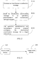
- a source node device sends an interference coordination message to an OAM (Operations, Administration and Maintenance, operation, administration and maintenance) network element, and the OAM configures the interference coordination message for a target node device, so that the target node device performs interference coordination according to the interference coordination message.
- OAM Operations, Administration and Maintenance, operation, administration and maintenance
- a process of the first embodiment of the interference coordination method in an LTE system according to the present invention includes: Step S110: Generate an interference coordination message, where the interference coordination message includes a priority configuration of each resource of multiple resources of a source node device.
- the priority configuration may include at least two or at least three priorities.
- the interference coordination message generated by the source node device may be shown in Table 1 below: Table 1 Message or field name or group name Type or value Range Description Cell/node information entry 1 to a maximum quantity of cells or nodes served by an eNB Cell ID or node ID ECGI A source cell ID or a source node ID A target cell ID or a target node ID Resource list 1 to a maximum quantity of resources Each resource corresponds to a position in the list: The first element in the list corresponds to a resource 0, and the second element in the list corresponds to a resource 1, and the like. Priority of each resource ENUMERATED (high, medium, low) The priority of each resource is represented by one of three states.
- the value range of the ⁇ cell information entry> is 1 to a maximum quantity of cells served by the eNB; and when the eNB in which the source node device is located includes only nodes with a same cell ID, the value range of the ⁇ cell information entry> may be 1 to a maximum quantity of nodes included by the eNB.
- the ⁇ cell ID or node ID> is used to identify a source node device or a target node device of the interference coordination message. If the source node device and the target node device have different cell IDs, the source node device and the target node device belong to different cells.
- a physical cell identifier or an ECGI E-UTRAN Cell Global Identifier, evolved universal terrestrial radio access network cell global identifier
- ECGI E-UTRAN Cell Global Identifier, evolved universal terrestrial radio access network cell global identifier
- the source node device and the target node device belong to a same cell.
- the ECGI may be used to identify the source node device and the target node device.
- the ⁇ cell ID or node ID> may include only a cell ID or a node ID of the target node device.
- the resource may be a resource granularity, may be a subframe in a time domain or an aggregation of several subframes, may be a physical resource block or a physical resource block pair, may be a partial physical resource block or a partial physical resource block pair, or may be a combination of the foregoing time-domain resource and frequency-domain resource.
- the partial physical resource block is a part of the physical resource block, and may be a part of one extended control channel element or a part of an aggregation of at least two extended control channel elements; and the partial physical resource block pair is a part of the physical resource block pair, and may be one extended control channel element or an aggregation of at least two extended control channel elements.
- One extended control channel element is a smallest resource for transmitting an ePDCCH.
- a resource block RB (resource block) mentioned in this specification is used to describe a mapping from a physical channel to a resource element (RE, resource element).
- a physical resource block is formed by a certain quantity x of successive OFDM symbols in a time domain and a certain quantity y of successive subcarriers in a frequency domain.
- a physical resource block is formed by x*y resource elements, which correspondingly is a time slot in the time domain and 180 kHz in the frequency domain.
- Each resource element may be identified by an antenna port, an OFDM symbol, and a subcarrier.
- one RB is formed by 7 OFDM symbols and 12 subcarriers; and for an extended CP, one RB is formed by 6 OFDM symbols and 12 subcarriers or is formed by 3 OFDM symbols and 24 subcarriers.
- One physical resource block pair (PRB pair) is formed by resource blocks of 2 time slots, where the resources blocks of 2 time slots may correspond to a same resource block number.
- the ⁇ priority of each resource> may be represented by using a bitmap below: Table 2 Priority of each resource BIT STRING (2S*M/n%) Every two bits in the bitmap correspond to one physical resource (for example, the first bit and the second bit correspond to a resource 0, and the rest may be deduced by analog), and four states 00, 01, 10, and 11 of every two bits separately represent a priority configuration of the resource corresponding to the bits.
- Table 2 shows a bitmap of each partial physical resource block obtained through division, that is, each physical resource, where a bandwidth S may be a preset system bandwidth, for example, 6 PRBs, 10 PRBs, 25 PRBs, 50 PRBs or 110 PRBs, and may also be another bandwidth configured for the interference coordination; M is the quantity of eCCEs (enhanced/extended control channel element, enhanced/extended control channel element) included in each PRB or each PRB pair, n is the quantity of eCCEs included in each physical resource divided in the source node device.
- a bandwidth S may be a preset system bandwidth, for example, 6 PRBs, 10 PRBs, 25 PRBs, 50 PRBs or 110 PRBs, and may also be another bandwidth configured for the interference coordination
- M is the quantity of eCCEs (enhanced/extended control channel element, enhanced/extended control channel element) included in each PRB or each PRB pair
- n is the quantity of eCCEs included in
- every two bits of six bits in the bitmap represent a priority configuration of the three physical resources, which may be specifically as follows: 00 represents a first priority, 01 represents a second priority, 10 represents a third priority, and 11 is a reserved bit.
- the interference coordination message in this embodiment of the present invention may indicate that a resource with a preset priority in the priority configuration is used to transmit a control channel or control message (may also be used to transmit another channel or another signal simultaneously), where the preset priority may specifically be the first priority or the highest priority.
- the preset priority shown in the foregoing Table 2 may be the first priority 00, of which a corresponding physical resource is used to transmit a control channel or control message, and physical resources of other priorities may be used to transmit a data channel.
- the control channel may be the ePDCCH
- the control message may be a message borne by a broadcast channel (PBCH, physical broadcast channel) or system information (SI, system information) or a paging message or an RACH (random access channel, random access channel) response message borne in a PDSCH, where the RACH response message is indicated by a PDCCH or an ePDCCH that has been scrambled by RA-RNTI (random access-radio network temporary identifier) or Temporary C-RNTI (temporary cell identifier) scrambling.
- RA-RNTI random access-radio network temporary identifier
- Temporary C-RNTI temporary cell identifier
- only one bit may be used to correspond to one physical resource, for example, 0 indicates the first priority, and 1 indicates the second priority.
- bitmap is represented as BIT STRING (S*M/n).
- the resource is a time-domain subframe or a subframe aggregation
- the implementation manner is similar to the manner of the foregoing physical resource, and every 1 or 2 bits in the bitmap is used to indicate a priority configuration of each subframe or each subframe aggregation obtained through division, which is not further described herein.
- the interference coordination message further includes a power configuration of at least partial resources of multiple resources of the source node device.
- a specific implementation manner may be as follows: 1) In the ⁇ priority of each resource>, only one bit is used to correspond to a priority of each physical resource, 0 indicates the first priority, and 1 indicates the second priority.
- the interference coordination message further includes an indication used to identify RNTP (Relative Narrowband Tx Power, relative narrowband transmit power) of each physical resource, which also uses one bit to identify whether transmit power of each physical resource exceeds an RNTP threshold, for example, 0 indicates that transmit power of a corresponding physical resource does not exceed a set RNTP threshold, and 1 indicates that the transmit power of the physical resource is not limited.
- RNTP Relative Narrowband Tx Power, relative narrowband transmit power
- each resource In the ⁇ priority of each physical resource>, two bits are used to indicate a priority of each physical resource, different symbols may correspond to a same priority and a same RNTP transmit power limitation or different RNTP transmit power limitations, as shown in Table 3 below: Table 3 Priority of each resource ENUMERATED (unlimited transmit power 1, unlimited transmit power 2, and limited transmit power) The priority of each resource is represented by one of three states. The unlimited transmit power has a higher priority compared with the limited transmit power. The unlimited transmit power 1 may have a higher priority than the unlimited transmit power 2. A limited power value of the transmit power may be indicated by an RNTP field.
- 00 is used to indicate the first priority
- 01 indicates the second priority and that the transmit power is not limited by the RNTP threshold
- 10 indicates the second priority but that the transmit power does not exceed the RNTP threshold
- 11 is still a reserved bit
- 00 is used to indicate the first priority and that the transmit power is not limited
- 01 indicates the second priority and that the transmit power is not limited
- 10 indicates the third priority and the transmit power does not exceed the RNTP threshold
- 11 indicates a fourth priority and that the transmit power does not exceed the RNTP threshold.
- the interference coordination message further includes a configuration of a resource used by the source node device to send a system message or a paging message.
- the source node device may add, to the interference coordination message, a time-domain and/or frequency-domain resource configuration that is used by the source node device to send a system message, or a paging message or an RACH response message or indicates that the target node sends a system message or a paging message or an RACH response message.
- the indication may also use the bitmap method.
- Table 4 and Table 5 below show a time-domain and/or frequency-domain resource configuration indicating that a system message or a paging message or an RACH response message is sent in an FDD (Frequency Division Duplexing, frequency division duplex) system and in a TDD (Time Division Duplexing, time division duplex) system separately: Table 4 In an FDD system Message name or field name Type or value Description System message or paging message subframe or RACH response message BIT STRING (SIZE (40)) Each bit of the bitmap represents a downlink subframe.
- FDD Frequency Division Duplexing, frequency division duplex
- TDD Time Division Duplexing, time division duplex
- bit 1 indicates that a system message or a paging message or an RACH response message is transmitted in the subframe, and 0 indicates the system message or the paging message or the RACH response message is not transmitted in the subframe.
- the first bit of the bitmap corresponds to a subframe 0.
- a 40-bit bitmap corresponds to a total of 40 subframes of 4 successive frames. The maximum quantity of subframes is 40.
- System message or paging message frequency-domain resource or RACH response message BIT STRING (S*M/n) Each bit of the bitmap represents a physical resource.
- Each bit of the bitmap represents a downlink subframe and/or an S subframe. 1 indicates that a system message or a paging message or an RACH response message is transmitted in the subframe, and 0 indicates the system message or the paging message or the RACH response message is not transmitted in the subframe.
- the first bit of the bitmap corresponds to a subframe 0.
- the maximum quantity of subframes depends on a UL/DL subframe configuration. For UL/DL configurations 1 to 5, the maximum quantity of subframes is 20; for UL/DL configuration 6, the maximum quantity of subframes is 60; and for UL/DL configuration 0, the maximum quantity of subframes is 70.
- a 70-bit bitmap corresponds to a total of 70 subframes of 7 successive frames.
- S*M/n Each bit of the bitmap represents a physical resource granularity. 1 indicates that a system message or a paging message or an RACH response message is transmitted on the physical resource, and 0 indicates the system message or the paging message or the RACH response message is not transmitted on the physical resource.
- each resource> in Table 1 may also be used to represent a resource used to transmit a system message or a paging message or an RACH response message, that is, a physical resource with a preset priority is used to transmit a system message or a paging message or an RACH response message.
- Step S120 Send the interference coordination message to an operation, administration and maintenance network element.
- the source node device may further send a start orthogonal frequency division multiplexing symbol OFDM symbol of an extended physical downlink control channel ePDCCH of the source node device or the target node device to the operation, administration and maintenance network element OAM.
- a message or a field may be defined, as shown in Table 6 below.
- Table 6 Message name or field name Type or value Description ePDCCH start symbol INTEGER (0 ⁇ 4) INTEGER (0 to 4) Value 0 indicates that the ePDCCH starts from an OFDM symbol 0; and value 1 indicates that the ePDCCH starts from an OFDM symbol 1. The rest may be deduced by analog.
- a carrier index may also be sent to the OAM.
- Table 7 a mapping between a carrier index value and a carrier frequency is carried in a system message from the source node device to the OAM.
- Table 7 Message name or field name Type or value Description Cell index INTERGER (0...7)
- a carrier index value ePDCCH start symbol INTEGER (0...4)
- An ePDCCH start OFDM symbol Value 0 indicates that the ePDCCH starts from an OFDM symbol 0; and value 1 indicates that the ePDCCH starts from an OFDM symbol 1. Another value is similar.
- Step S130 The operation, administration and maintenance network element configures the interference coordination message for the target node device, so that the target node device performs interference coordination according to the interference coordination message.
- the OAM may directly configure, for the target node, the interference coordination message that is acquired from the source node device; or, the OAM may first perform information processing on the acquired interference coordination message, and then configure the processed interference coordination message for the target node device.
- the target node device configures, corresponding to a priority of a resource of the source node device and in the interference coordination message, transmit power, a priority, and the like of a resource of the target node device.
- the target node device reserves and does not use a resource which has a same frequency or a same time domain as the source node device; if the resource is already used, the target node device replaces the resource with another resource, and even reserves a certain protection frequency band; for a resource with the second highest priority of the source node device, the target node device may reduce transmit power of a resource which has a same frequency or a same time domain as the source node device or set the resource to a low priority; for a resource with a low priority of the source node device, the target node device may use a resource which has a same frequency or a same time domain as the source node device to transmit a control channel or a control message or set the resource to a high priority, or the like, so as to reduce interference to a neighboring cell of the source node device.
- the target node device may further skip sending a channel or a signal on the resource according to the time-domain and/or frequency-domain resource configuration used to send a system message or a paging message or an RACH response message and in the interference coordination message; or send a system message or a paging message or an RACH response message on the resource according to an indication.
- the OAM further receives a start OFDM symbol of the ePDCCH, of the source node device or the target node device, sent by the source node device, the OAM sends the start OFDM symbol of the ePDCCH of the source node device or a start OFDM symbol of the ePDCCH that should be configured by the target node device to the target node device; the target node device performs interference coordination according to the start OFDM symbol of the ePDCCH of the source node device or the start OFDM symbol of the ePDCCH that should be configured by the target node device and notified by the source node device, including selecting an end OFDM symbol of a PDCCH of the target node device or a start OFDM symbol of the ePDCCH of the target node device according to the start OFDM symbol of the ePDCCH of the source node device, and setting the end OFDM symbol of the PDCCH of the target node device or the start OFDM symbol of the ePDCCH of the target node device
- FIG. 3 is a structural diagram of a system that implements a second embodiment of an interference coordination method in an LTE system according to the present invention.
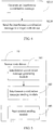
- a source node device sends an interference coordination message to a target node device directly, so that a target network element performs interference coordination according to the interference coordination message.
- a process of the second embodiment of the interference coordination method in an LTE system according to the present invention includes:
- the source node device may further send a start orthogonal frequency division multiplexing symbol OFDM symbol of an extended physical downlink control channel ePDCCH of the source node device or the target node device to the target node device.
- the specific implementation manner is the same as that in the first embodiment.
- the start OFDM symbol may be sent to the target source node device by defining a message or a field individually, and may also be sent, together with a carrier index, to the target source node device.
- the target node device modulates an end OFDM symbol of a PDCCH of the target node device or the start OFDM symbol of the ePDCCH of the target node device according to the start OFDM symbol of the ePDCCH of the source device or the target node device, so as to avoid causing interference to a PDCCH of the source node device or suffering interference from the PDCCH of the source node device.
- FIG. 5 is a schematic structural diagram of a source node device for implementing interference coordination according to an embodiment of the present invention.
- the source node device for implementing interference coordination according to this embodiment of the present invention may at least include:
- An interference coordination message generating module 101 is configured to generate an interference coordination message, where the interference coordination message includes a priority configuration of each resource of multiple resources of the source node device.
- the priority configuration may include at least two or at least three priorities.
- the interference coordination message generated by the interference coordination message generating module may be shown in Table 8 below: Table 8 Message or field name or group name Type or value Range Description Cell/node information entry 1 to a maximum quantity of cells or nodes served by an eNB Cell ID or node ID ECGI A source cell ID or a source node ID A target cell ID or a target node ID Resource list 1 to a maximum quantity of resources Each resource corresponds to a position in the list: The first element in the list corresponds to a resource 0, and the second element in the list corresponds to a resource 1, and the like. Priority of each resource ENUMERATED (high, medium, low) The priority of each resource is represented by one of three states.
- the value range of the ⁇ cell information entry> is 1 to a maximum quantity of cells served by the eNB; when the eNB in which the source node device is located includes only nodes with a same cell ID, the value range of the ⁇ cell information entry> may be 1 to a maximum quantity of nodes included by the eNB.
- the ⁇ cell ID or node ID> is used to identify a source node device or a target node device of the interference coordination message. If the source node device and the target node device have different cell IDs, the source node device and the target node device belong to different cells.
- a physical cell identifier or an ECGI E-UTRAN Cell Global Identifier, evolved universal terrestrial radio access network cell global identifier
- E-UTRAN Cell Global Identifier evolved universal terrestrial radio access network cell global identifier
- the source node device and the target node device belong to a same cell.
- the ECGI must be used to identify the source node device and the target node device.
- the resource may be a resource granularity, may be a subframe in a time domain or an aggregation of several subframes, may be a physical resource block or a physical resource block pair, may be a partial physical resource block or a partial physical resource block pair, or may be a combination of the foregoing time-domain resource and frequency-domain resource.
- the partial physical resource block is a part of the physical resource block, and may further be a part of one extended control channel element or a part of an aggregation of at least two extended control channel elements; and the partial physical resource block pair is a part of the physical resource block pair, and may further be one extended control channel element or an aggregation of at least two extended control channel elements.
- the ⁇ priority of each resource> may be represented by using a bitmap shown in Table 7 below: Table 9 Priority of each resource BIT STRING (2S*M/n%) Every two bits in the bitmap correspond to one physical resource (for example, the first bit and the second bit correspond to a resource 0, and the rest may be deduced by analog), and four states 00, 01, 10, and 11 of every two bits separately represent a priority configuration of the resource corresponding to the bits.
- Table 9 shows a bitmap of each partial physical resource block obtained through division, that is, each physical resource, where a bandwidth S may be a preset system bandwidth, for example, 6 PRBs, 10 PRBs, 25 PRBs, 50 PRBs or 110 PRBs, and may also be another bandwidth configured for the interference coordination; M is the quantity of eCCEs (enhanced/extended control channel element, enhanced/extended control channel element) included in each PRB or each PRB pair, n is the quantity of eCCEs included in each physical resource divided in the source node device.
- a bandwidth S may be a preset system bandwidth, for example, 6 PRBs, 10 PRBs, 25 PRBs, 50 PRBs or 110 PRBs, and may also be another bandwidth configured for the interference coordination
- M is the quantity of eCCEs (enhanced/extended control channel element, enhanced/extended control channel element) included in each PRB or each PRB pair
- n is the quantity of eCCEs included in
- every two bits of six bits in the bitmap represent a priority configuration of the three physical resources, which may be specifically as follows: 00 represents a first priority, 01 represents a second priority, 10 represents a third priority, and 11 is a reserved bit.
- the interference coordination message in this embodiment of the present invention may indicate that a resource with a preset priority in the priority configuration is used to transmit a control channel or control message (may also be used to transmit another channel or another signal simultaneously), where the preset priority may specifically be the first priority or the highest priority.
- the preset priority shown in the foregoing Table 9 may be the first priority 00, of which a corresponding physical resource is used to transmit a control channel or control information, and physical resources of other priorities may be used to transmit a data channel.
- the control channel may be an ePDCCH
- the control message may be a broadcast channel or a system message or an RACH response message borne in a PDSCH.
- only one bit may be used to correspond to one physical resource, for example, 0 indicates the first priority, and 1 indicates the second priority.
- the bitmap is represented as BIT STRING (S*M/n).
- the resource is a time-domain subframe or a subframe aggregation
- the implementation manner is similar to the manner of the foregoing physical resource, and every 1 or 2 bits in the bitmap is used to indicate a priority configuration of each subframe or each subframe aggregation obtained through division, which is not further described herein.
- the interference coordination message further includes a power configuration of at least partial resources of multiple resources of the source node device.
- a specific implementation manner may be as follows: 1) In the ⁇ priority of each resource>, only one bit is used to correspond to a priority of each physical resource, 0 indicates the first priority, and 1 indicates the second priority.
- the interference coordination message further includes an indication used to identify RNTP (Relative Narrowband Tx Power, relative narrowband transmit power) of each physical resource, which also uses one bit to identify whether transmit power of each physical resource exceeds an RNTP threshold, for example, 0 indicates that transmit power of a corresponding physical resource does not exceed a set RNTP threshold, and 1 indicates that the transmit power of the physical resource is not limited.
- RNTP Relative Narrowband Tx Power, relative narrowband transmit power
- each resource In the ⁇ priority of each physical resource>, two bits are used to indicate a priority of each physical resource, different symbols may correspond to a same priority and a same RNTP transmit power limitation or different RNTP transmit power limitations, as shown in Table 10 below: Table 10 Priority of each resource ENUMERATED (unlimited transmit power 1, unlimited transmit power 2, and limited transmit power) The priority of each resource is represented by one of three states. The unlimited transmit power has a higher priority compared with the limited transmit power. The unlimited transmit power 1 may have a higher priority than the unlimited transmit power 2. A limited power value of the transmit power may be indicated by an RNTP field.
- 00 is used to indicate the first priority
- 01 indicates the second priority and that the transmit power is not limited by the RNTP threshold
- 10 indicates the second priority but that the transmit power does not exceed the RNTP threshold
- 11 is still a reserved bit
- 00 is used to indicate the first priority and that the transmit power is not limited
- 01 indicates the second priority and that the transmit power is not limited
- 10 indicates the third priority and the transmit power does not exceed the RNTP threshold
- 11 indicates a fourth priority and that the transmit power does not exceed the RNTP threshold.
- the interference coordination message further includes a configuration of a resource used by the source node device to send a system message or a paging message or an RACH response message.
- the source node device may add, to the interference coordination message, a time-domain and/or frequency-domain resource configuration that is used by the source node device to send a system message, or a paging message or an RACH response message or indicates that the target node sends a system message, or a paging message or an RACH response message.
- the indication may also use the bitmap method.
- Table 7 and Table 8 below show a time-domain and/or frequency-domain resource configuration indicating that a system message or a paging message or an RACH response message is sent in an FDD (Frequency Division Duplexing, frequency division duplex) system and in a TDD (Time Division Duplexing, time division duplex) system separately: Table 11 In an FDD system Message name or field name Type or value Description System message or paging message subframe or RACH response message subframe BIT STRING (SIZE (40)) Each bit of the bitmap represents a downlink subframe.
- FDD Frequency Division Duplexing, frequency division duplex
- TDD Time Division Duplexing, time division duplex
- bit 1 indicates that a system message or a paging message or an RACH response message is transmitted in the subframe, and 0 indicates the system message or the paging message or the RACH response message is not transmitted in the subframe.
- the first bit of the bitmap corresponds to a subframe 0.
- a 40-bit bitmap corresponds to a total of 40 subframes of 4 successive frames. The maximum quantity of subframes is 40.
- System message or paging message or RACH response message frequency-domain resource BIT STRING (S*M/n) Each bit of the bitmap represents a physical resource.
- Each bit of the bitmap represents a downlink subframe and/or an S subframe. 1 indicates that a system message or a paging message or an RACH response message is transmitted in the subframe, and 0 indicates the system message or the paging message or the RACH response message is not transmitted in the subframe.
- the first bit of the bitmap corresponds to a subframe 0.
- the maximum quantity of subframes depends on a UL/DL subframe configuration. For UL/DL configurations 1 to 5, the maximum quantity of subframes is 20; for UL/DL configuration 6, the maximum quantity of subframes is 60; and for UL/DL configuration 0, the maximum quantity of subframes is 70.
- a 70-bit bitmap corresponds to a total of 70 subframes of 7 successive frames.
- S*M/n System message or paging message or RACH response message frequency-domain resource BIT STRING (S*M/n)
- Each bit of the bitmap represents a physical resource. 1 indicates that a system message or a paging message or an RACH response message is transmitted on the physical resource, and 0 indicates the system message or the paging message or the RACH response message is not transmitted on the physical resource.
- each resource> in Table 6 may also be used to represent a resource used to transmit a system message or a paging message or an RACH response message, that is, a physical resource with a preset priority is used to transmit a system message or a paging message. It may be understood that this solution may also be implemented by sending only a configuration of a time-domain resource or sending only a frequency-domain resource to the target node device.
- a time-domain resource configuration used to send a system message or a paging message or an RACH response message may be sent to the target node, so that the target node device can know, according to a resource with a preset priority in the frequency domain, a resource used by the source node device to transmit a system message or a paging message or an RACH response message.
- An interference coordination message sending module 102 is configured to send the interference coordination message to a target node device, so that the target node device performs interference coordination according to the interference coordination message; or configured to send the interference coordination message to an operation, administration and maintenance network element, so that the operation, administration and maintenance network element configures the interference coordination message for the target node device, so that the target node device performs interference coordination according to the interference coordination message.
- the OAM may directly configure, for the target node, the interference coordination message that is acquired from the source node device; or, the OAM may first perform information processing on the acquired interference coordination message, and then configures the processed interference coordination message for the target node device.
- the source node device may further include: a start symbol sending module 103, configured to send a start orthogonal frequency division multiplexing symbol of an extended physical downlink control channel of the source node device or the target node device to the target node device, so that the target node device performs interference coordination according to the interference coordination message and the start orthogonal frequency division multiplexing symbol of the extended physical downlink control channel; or configured to send a start orthogonal frequency division multiplexing symbol of an extended physical downlink control channel of the source node device or the target node device to an operation, administration and maintenance network element, so that the operation, administration and maintenance network element configures the start orthogonal frequency division multiplexing symbol of the extended physical downlink control channel of the source node device or the target node device for the target node device, so that the target node device performs interference coordination according to the interference coordination message and the start orthogonal frequency division multiplexing symbol of the extended physical downlink control channel.
- a start symbol sending module 103 configured to send a start orthogonal frequency division multiple
- the symbol sending module 103 may send the start OFDM symbol of the ePDCCH of the source node device or the target node device by defining a message or a field, as shown in Table 13 below.
- Table 13 Message name or field name Type or value Description ePDCCH start symbol INTEGER (0 to 4) Value 0 indicates that the ePDCCH starts from an OFDM symbol 0; and value 1 indicates that the ePDCCH starts from an OFDM symbol 1. The rest may be deduced by analog.
- the start symbol sending module 103 may also send a carrier index to the OAM.
- a mapping between a carrier index value and a carrier frequency may be carried in a system message from the source node device to the OAM.
- Table 14 Message name or field name Type or value Description Cell index INTERGER (0...7)
- a carrier index value ePDCCH start symbol INTEGER (0...4)
- An ePDCCH start OFDM symbol Value 0 indicates that the ePDCCH starts from an OFDM symbol 0; and value 1 indicates that the ePDCCH starts from an OFDM symbol 1. Another value is similar.
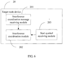
- FIG. 6 is a schematic structural diagram of a target node device for implementing interference coordination according to an embodiment of the present invention.
- the target node device of the present invention may at least include:
- An interference coordination message receiving module 201 is configured to receive an interference coordination message.
- the receiving an interference coordination message is receiving the interference coordination message from a source node device or receiving the interference coordination message from an operation, administration and maintenance network element.
- the OAM may directly configure, for a target node, the interference coordination message that is acquired from the source node device; or, the OAM may first perform information processing on the acquired interference coordination message, and then configures the processed interference coordination message for the target node device.
- Content included in the interference coordination message is similar to that in the interference coordination message acquired by the foregoing interference coordination message generating module 101, which is not further described herein.
- An interference coordination module 202 is configured to perform interference coordination according to the interference coordination message. During a specific implementation, after receiving the interference coordination message, the interference coordination module 202 configures, corresponding to a priority of a resource of the source node device and in the interference coordination message, transmit power, a priority, and the like of a resource of the interference coordination module 202, for example, for a resource with the highest priority of the source node device, the interference coordination module 202 reserves and does not use resources in a same frequency domain or in a same time domain of the target node device; if the resources are already used, the interference coordination module 202 replaces the resources with other resources, and even reserves a certain protection frequency band; for a resource with the second highest priority of the source node device, the interference coordination module 202 may reduce transmit power of resources in a same frequency domain or in a same time domain of the target node device; for a resource with a low priority of the source node device, the interference coordination module 202 may use resources in a same frequency domain or in a same time
- the interference coordination module 202 perform interference coordination according to the interference coordination message may further include: skipping sending a channel or a signal on the resource according to the time-domain and/or frequency-domain resource configuration used to send a system message or a paging message or an RACH response message and in the interference coordination message; or sending a system message or a paging message or an RACH response message on the resource according to an indication.
- the target node device may further include: a start symbol receiving module 203, configured to receive, from the source node device or the OAM, a start OFDM symbol of an ePDCCH of the source node device or a start OFDM symbol of an ePDCCH of the target node device.
- a start symbol receiving module 203 configured to receive, from the source node device or the OAM, a start OFDM symbol of an ePDCCH of the source node device or a start OFDM symbol of an ePDCCH of the target node device.
- the interference coordination module 202 may perform interference coordination according to the start OFDM symbol of the ePDCCH of the source node device or the start OFDM symbol of the ePDCCH of the target node device, which is received by the start symbol receiving module 203, including determining an end OFDM symbol of a PDCCH of the target node device or a start OFDM symbol of the ePDCCH of the target node device according to the start OFDM symbol of the ePDCCH of the source node device or the start OFDM symbol of the ePDCCH of the target node device, so as to avoid causing interference to a PDCCH of the source node device or suffering interference from the PDCCH of the source node device.
- interference coordination is implemented with higher efficiency, and it is further ensured that a resource used to transmit a control channel is free from interference.
- a person of ordinary skill in the art may understand that all or a part of the processes of the methods in the embodiments may be implemented by a computer program instructing relevant hardware.
- the program may be stored in a computer readable storage medium. When the program runs, the processes of the methods in the embodiments are performed.
- the foregoing storage medium may include: a magnetic disk, an optical disc, a read-only memory (Read-Only Memory, ROM), or a random access memory (Random Access Memory, RAM).
Landscapes
- Engineering & Computer Science (AREA)
- Signal Processing (AREA)
- Computer Networks & Wireless Communication (AREA)
- Quality & Reliability (AREA)
- Mobile Radio Communication Systems (AREA)
Priority Applications (1)
| Application Number | Priority Date | Filing Date | Title |
|---|---|---|---|
| EP18153613.7A EP3383117A1 (fr) | 2012-07-30 | 2012-07-30 | Procédé de coordination d'interférence dans un système lte |
Applications Claiming Priority (3)
| Application Number | Priority Date | Filing Date | Title |
|---|---|---|---|
| EP12882329.1A EP2822343B1 (fr) | 2012-07-30 | 2012-07-30 | Procédé de coordination d'interférences dans un système lte |
| EP18153613.7A EP3383117A1 (fr) | 2012-07-30 | 2012-07-30 | Procédé de coordination d'interférence dans un système lte |
| PCT/CN2012/079346 WO2014019121A1 (fr) | 2012-07-30 | 2012-07-30 | Procédé de coordination d'interférences dans un système lte |
Related Parent Applications (2)
| Application Number | Title | Priority Date | Filing Date |
|---|---|---|---|
| EP12882329.1A Division EP2822343B1 (fr) | 2012-07-30 | 2012-07-30 | Procédé de coordination d'interférences dans un système lte |
| EP12882329.1A Division-Into EP2822343B1 (fr) | 2012-07-30 | 2012-07-30 | Procédé de coordination d'interférences dans un système lte |
Publications (1)
| Publication Number | Publication Date |
|---|---|
| EP3383117A1 true EP3383117A1 (fr) | 2018-10-03 |
Family
ID=50027053
Family Applications (2)
| Application Number | Title | Priority Date | Filing Date |
|---|---|---|---|
| EP18153613.7A Withdrawn EP3383117A1 (fr) | 2012-07-30 | 2012-07-30 | Procédé de coordination d'interférence dans un système lte |
| EP12882329.1A Not-in-force EP2822343B1 (fr) | 2012-07-30 | 2012-07-30 | Procédé de coordination d'interférences dans un système lte |
Family Applications After (1)
| Application Number | Title | Priority Date | Filing Date |
|---|---|---|---|
| EP12882329.1A Not-in-force EP2822343B1 (fr) | 2012-07-30 | 2012-07-30 | Procédé de coordination d'interférences dans un système lte |
Country Status (4)
| Country | Link |
|---|---|
| US (2) | US9960891B2 (fr) |
| EP (2) | EP3383117A1 (fr) |
| CN (1) | CN103797878B (fr) |
| WO (1) | WO2014019121A1 (fr) |
Families Citing this family (10)
| Publication number | Priority date | Publication date | Assignee | Title |
|---|---|---|---|---|
| CN105451354B (zh) * | 2014-08-15 | 2019-01-25 | 上海诺基亚贝尔股份有限公司 | 基于小区间干扰协调参数实现调度用户的方法与设备 |
| CN106656446B (zh) * | 2015-11-03 | 2020-06-26 | 中兴通讯股份有限公司 | 参考信号的发送方法及装置、接收方法及装置 |
| DE102016215915A1 (de) * | 2016-08-24 | 2018-03-01 | Siemens Aktiengesellschaft | Sicheres Konfigurieren eines Gerätes |
| WO2018232177A1 (fr) * | 2017-06-14 | 2018-12-20 | Motorola Mobility Llc | Exécution d'une résolution de conflit relative à des demandes d'informations sur un système |
| US10009832B1 (en) * | 2017-08-11 | 2018-06-26 | At&T Intellectual Property I, L.P. | Facilitating compact signaling design for reserved resource configuration in wireless communication systems |
| GB2572651A (en) * | 2018-04-06 | 2019-10-09 | Nec Corp | Communication system |
| US11297654B2 (en) * | 2019-03-28 | 2022-04-05 | Mediatek Inc. | Methods and apparatus to transmit with resources overlapped |
| US12096464B2 (en) * | 2020-09-21 | 2024-09-17 | Samsung Electronics Co., Ltd. | Methods and apparatus for interference reduction and coordination |
| CN117296379A (zh) | 2021-03-11 | 2023-12-26 | 诺基亚技术有限公司 | 针对移动性的干扰协调 |
| US12096258B2 (en) * | 2021-09-21 | 2024-09-17 | Spectrum Effect Inc. | Classifying RF interference sources using machine learning and operations, administration, and management data |
Citations (5)
| Publication number | Priority date | Publication date | Assignee | Title |
|---|---|---|---|---|
| WO2011029469A1 (fr) * | 2009-09-09 | 2011-03-17 | Telefonaktiebolaget Lm Ericsson (Publ) | Procédés et appareils pour coordination d'interférence dans un système de télécommunications |
| WO2011119750A1 (fr) * | 2010-03-23 | 2011-09-29 | Interdigital Patent Holdings, Inc. | Procédé, appareil et système permettant une coordination de ressources dans des réseaux cellulaires |
| EP2373109A1 (fr) * | 2008-12-30 | 2011-10-05 | China Academy of Telecommunications Technology | Procédé de coordination d'interférence et dispositif de réseau d'accès |
| WO2012008773A2 (fr) * | 2010-07-16 | 2012-01-19 | 엘지전자 주식회사 | Procédé et appareil de commande de puissance d'émission de liaison montante dans système de communication sans fil |
| WO2012072097A1 (fr) * | 2010-11-29 | 2012-06-07 | Nokia Siemens Networks Oy | Sélection de porteuses dans des systèmes de relais |
Family Cites Families (42)
| Publication number | Priority date | Publication date | Assignee | Title |
|---|---|---|---|---|
| JP2008501284A (ja) * | 2004-06-16 | 2008-01-17 | サムスン エレクトロニクス カンパニー リミテッド | 直交周波数分割多元接続方式を使用する移動通信システムにおけるデータを送受信する方法 |
| ES2555777T3 (es) * | 2006-04-28 | 2016-01-08 | Panasonic Intellectual Property Corporation Of America | Dispositivo de estación base de comunicación de radio y método de comunicación de radio usado para comunicación multi-portadora |
| US8937911B2 (en) * | 2006-08-31 | 2015-01-20 | Futurewei Technologies, Inc. | Method and system for sharing resources in a wireless communication network |
| CN101534474B (zh) * | 2008-03-14 | 2015-06-03 | 中兴通讯股份有限公司 | 一种配置单频网多播广播帧的方法 |
| US8559359B2 (en) * | 2008-04-29 | 2013-10-15 | Qualcomm Incorporated | Information exchange mechanisms to achieve network QoS in wireless cellular systems |
| KR101199389B1 (ko) * | 2008-05-09 | 2012-11-12 | 엘지전자 주식회사 | 무선접속시스템에서 페이징 수행 방법 |
| KR20090127031A (ko) * | 2008-06-04 | 2009-12-09 | 삼성전자주식회사 | 무선통신 시스템에서 단말의 유휴 모드를 지원하기 위한 방법 및 장치 |
| US8934417B2 (en) * | 2009-03-16 | 2015-01-13 | Google Technology Holdings LLC | Resource allocation in wireless communication systems |
| CN101860869B (zh) | 2009-04-09 | 2015-01-28 | 中兴通讯股份有限公司 | 小区之间干扰协调指示信息的发送方法和系统 |
| BRPI0925324A2 (pt) * | 2009-04-17 | 2016-04-26 | Huawei Tech Co Ltd | método de coordenação de interferência inter-células de enlace descendente e nó b evolúido |
| CN101873722B (zh) | 2009-04-24 | 2012-08-08 | 电信科学技术研究院 | 通知mbsfn子帧配置的方法和装置 |
| US9634806B2 (en) * | 2009-06-11 | 2017-04-25 | Qualcomm Incorporated | Data prioritization for a power-limited UE in a wireless communication system |
| US8340677B2 (en) * | 2009-07-02 | 2012-12-25 | Futurewei Technologies, Inc. | System and method for semi-static downlink inter-cell interference coordination for wireless communications |
| CN101998642B (zh) | 2009-08-19 | 2014-08-20 | 株式会社Ntt都科摩 | 一种小区间干扰协调方法及基站 |
| US8599768B2 (en) * | 2009-08-24 | 2013-12-03 | Intel Corporation | Distributing group size indications to mobile stations |
| KR101646789B1 (ko) * | 2010-01-19 | 2016-08-08 | 삼성전자주식회사 | 이동통신 시스템에서 캐리어 활성화 방법 및 장치 |
| KR101755022B1 (ko) * | 2010-03-05 | 2017-07-06 | 한국전자통신연구원 | 기지국, 이동국, 페이징 메시지 전송 방법, 그리고 페이징 메시지의 수신 방법 |
| WO2011139120A2 (fr) * | 2010-05-07 | 2011-11-10 | 엘지전자 주식회사 | Terminal adapté pour contrôler une puissance de transmission sur la liaison montante et procédé adapté pour contrôler une puissance de transmission sur la liaison montante dans un système de communication sans fil |
| WO2011148211A1 (fr) | 2010-05-26 | 2011-12-01 | Telefonaktiebolaget L M Ericsson (Publ) | Procédés et systèmes de localisation d'équipement utilisateur à l'aide d'une coordination de brouillage entre cellules |
| US8588797B2 (en) * | 2010-06-17 | 2013-11-19 | Nokia Siemens Networks Oy | Optimizing control channel performance with virtual inter-cell coordination |
| KR20120006881A (ko) * | 2010-07-13 | 2012-01-19 | 삼성전자주식회사 | Ofdm 계층셀 시스템에서 셀 간 간섭 조절 방법 및 장치 |
| CN102413499B (zh) | 2010-09-20 | 2014-09-10 | 大唐移动通信设备有限公司 | 一种小区间干扰协调的模拟方法及设备 |
| CN102457915B (zh) * | 2010-10-26 | 2016-03-02 | 株式会社Ntt都科摩 | 管理x2接口的方法、切换方法、干扰抑制方法及装置 |
| CN101982991B (zh) * | 2010-11-16 | 2013-01-23 | 西安电子科技大学 | 基于异构业务QoS的LTE网络小区间干扰协调方法 |
| US9504027B2 (en) * | 2010-11-25 | 2016-11-22 | Lg Electronics Inc. | Method and apparatus for transmitting a control channel and a data channel in a wireless communication system |
| CN102573082B (zh) * | 2010-12-20 | 2017-02-15 | 上海贝尔股份有限公司 | 在无线通信系统的相邻小区间进行干扰协调的方法与设备 |
| CN102026390B (zh) * | 2010-12-31 | 2013-01-09 | 大唐移动通信设备有限公司 | 基站及其实现小区间干扰协调的资源分配方法 |
| KR101809958B1 (ko) * | 2011-02-06 | 2017-12-18 | 엘지전자 주식회사 | 무선 통신 시스템에서 셀간 간섭 조정 방법 및 장치 |
| CN102149100B (zh) * | 2011-04-25 | 2013-09-18 | 东南大学 | 移动通信系统分层异构网络中的强化干扰协调方法 |
| US9380559B2 (en) * | 2011-05-08 | 2016-06-28 | Lg Electronics Inc. | Method and apparatus for transmitting multicast data to M2M devices in a wireless access system |
| US9264204B2 (en) * | 2011-08-17 | 2016-02-16 | Lg Electronics Inc. | Method and apparatus for inter-cell interference coordination for transmission point group |
| CN102291785B (zh) * | 2011-09-21 | 2014-08-20 | 电信科学技术研究院 | 小区间资源协调的方法和设备 |
| KR20140097160A (ko) * | 2011-10-18 | 2014-08-06 | 엘지전자 주식회사 | 무선 통신 시스템에서 셀 간 간섭을 완화하는 방법 및 이를 위한 장치 |
| US9705654B2 (en) * | 2011-11-08 | 2017-07-11 | Apple Inc. | Methods and apparatus for an extensible and scalable control channel for wireless networks |
| US9363809B2 (en) * | 2011-11-23 | 2016-06-07 | Lg Electronics Inc. | Method and wireless device for monitoring control channel |
| US9241327B2 (en) * | 2012-01-23 | 2016-01-19 | Intel Corporation | LTE enhancements for small packet transmissions |
| CN103297979B (zh) * | 2012-02-29 | 2016-08-03 | 国际商业机器公司 | 实现干扰协调的方法和基站 |
| KR20150009956A (ko) * | 2012-04-20 | 2015-01-27 | 엘지전자 주식회사 | 채널 상태 보고 방법 및 이를 위한 장치 |
| US9166718B2 (en) * | 2012-05-11 | 2015-10-20 | Intel Corporation | Downlink control indication for a stand-alone new carrier type (NCT) |
| WO2013169165A1 (fr) * | 2012-05-11 | 2013-11-14 | Telefonaktiebolaget L M Ericsson (Publ) | Appareil et procédé pour l'ordonnancement dans le sens descendant |
| WO2013176822A2 (fr) * | 2012-05-25 | 2013-11-28 | Motorola Mobility Llc | Réduction des effets d'interférence rencontrés par un dispositif de communication |
| GB2505907A (en) * | 2012-09-13 | 2014-03-19 | Vodafone Ip Licensing Ltd | Coordinating allocation of resource blocks to cell edge users based on a high priority indication |
-
2012
- 2012-07-30 EP EP18153613.7A patent/EP3383117A1/fr not_active Withdrawn
- 2012-07-30 EP EP12882329.1A patent/EP2822343B1/fr not_active Not-in-force
- 2012-07-30 CN CN201280021815.7A patent/CN103797878B/zh active Active
- 2012-07-30 WO PCT/CN2012/079346 patent/WO2014019121A1/fr not_active Ceased
-
2014
- 2014-09-25 US US14/496,817 patent/US9960891B2/en active Active
-
2018
- 2018-03-27 US US15/937,667 patent/US20180219655A1/en not_active Abandoned
Patent Citations (6)
| Publication number | Priority date | Publication date | Assignee | Title |
|---|---|---|---|---|
| EP2373109A1 (fr) * | 2008-12-30 | 2011-10-05 | China Academy of Telecommunications Technology | Procédé de coordination d'interférence et dispositif de réseau d'accès |
| WO2011029469A1 (fr) * | 2009-09-09 | 2011-03-17 | Telefonaktiebolaget Lm Ericsson (Publ) | Procédés et appareils pour coordination d'interférence dans un système de télécommunications |
| WO2011119750A1 (fr) * | 2010-03-23 | 2011-09-29 | Interdigital Patent Holdings, Inc. | Procédé, appareil et système permettant une coordination de ressources dans des réseaux cellulaires |
| WO2012008773A2 (fr) * | 2010-07-16 | 2012-01-19 | 엘지전자 주식회사 | Procédé et appareil de commande de puissance d'émission de liaison montante dans système de communication sans fil |
| US20130114562A1 (en) * | 2010-07-16 | 2013-05-09 | Lg Electronics Inc. | Method and apparatus for controlling uplink transmission power in wireless communication system |
| WO2012072097A1 (fr) * | 2010-11-29 | 2012-06-07 | Nokia Siemens Networks Oy | Sélection de porteuses dans des systèmes de relais |
Also Published As
| Publication number | Publication date |
|---|---|
| EP2822343A1 (fr) | 2015-01-07 |
| US9960891B2 (en) | 2018-05-01 |
| CN103797878A (zh) | 2014-05-14 |
| US20150009944A1 (en) | 2015-01-08 |
| EP2822343B1 (fr) | 2018-03-14 |
| CN103797878B (zh) | 2017-09-26 |
| EP2822343A4 (fr) | 2015-03-11 |
| WO2014019121A1 (fr) | 2014-02-06 |
| US20180219655A1 (en) | 2018-08-02 |
Similar Documents
| Publication | Publication Date | Title |
|---|---|---|
| US11949627B2 (en) | Wireless resource determination and use | |
| CN110972515B (zh) | 在无线通信系统中监测终端的控制信号的方法及其终端 | |
| EP2822343B1 (fr) | Procédé de coordination d'interférences dans un système lte | |
| US10979128B1 (en) | Beam failure and consistent listen before talk failure recovery | |
| US11211990B2 (en) | Beam failure recovery in multi-TRP scenarios | |
| EP3629492B1 (fr) | Configuration de faisceau pour des cellules secondaires | |
| US12355614B2 (en) | Failure recovery and beam selection in wireless communications | |
| EP3609285B1 (fr) | Gestion de ressources pour des procédures de reprise après défaillance de faisceau | |
| US10757621B2 (en) | Conditional handover execution | |
| EP3413658B1 (fr) | Dispositif de terminal, dispositif de station de base et procédé de communication | |
| US20230262814A1 (en) | Method and apparatus for handling small data transmission in rrc_inactive state in a wireless communication system | |
| US10462813B2 (en) | Method and apparatus for contention-based granting in a wireless communication network | |
| EP3413528B1 (fr) | Dispositif terminal, et procédé de communication | |
| US10182372B2 (en) | Method for transmitting D2D signal in wireless communication system and device therefor | |
| AU2017215651B2 (en) | Terminal device, base station device, and communication method | |
| US20150131599A1 (en) | Method for transmitting and receiving downlink control information, serving node and user equipment | |
| US20190166619A1 (en) | User terminal and radio communication method | |
| US20230397089A1 (en) | Mobile communication system | |
| TW201840231A (zh) | 處理共同搜尋空間的裝置及方法 | |
| WO2020065004A1 (fr) | Groupement d'équipement utilisateur flexible destiné à des signaux de réveil | |
| US20240057100A1 (en) | Method and apparatus for mbs reception in rrc idle and rrc inactive state in wireless communication system | |
| CN107211438A (zh) | 终端装置、基站装置、通信方法以及集成电路 | |
| US10932300B2 (en) | Communication control method, radio terminal, and base station | |
| CN111034321B (zh) | 终端在无线通信系统中发送上行链路信号的方法及使用该方法的终端 | |
| CN109275184B (zh) | 一种消息的发送方法和装置 |
Legal Events
| Date | Code | Title | Description |
|---|---|---|---|
| PUAI | Public reference made under article 153(3) epc to a published international application that has entered the european phase |
Free format text: ORIGINAL CODE: 0009012 |
|
| AC | Divisional application: reference to earlier application |
Ref document number: 2822343 Country of ref document: EP Kind code of ref document: P |
|
| AK | Designated contracting states |
Kind code of ref document: A1 Designated state(s): AL AT BE BG CH CY CZ DE DK EE ES FI FR GB GR HR HU IE IS IT LI LT LU LV MC MK MT NL NO PL PT RO RS SE SI SK SM TR |
|
| 17P | Request for examination filed |
Effective date: 20190403 |
|
| RBV | Designated contracting states (corrected) |
Designated state(s): AL AT BE BG CH CY CZ DE DK EE ES FI FR GB GR HR HU IE IS IT LI LT LU LV MC MK MT NL NO PL PT RO RS SE SI SK SM TR |
|
| STAA | Information on the status of an ep patent application or granted ep patent |
Free format text: STATUS: THE APPLICATION IS DEEMED TO BE WITHDRAWN |
|
| 18D | Application deemed to be withdrawn |
Effective date: 20200201 |