EP3384096B1 - Agencement pour produire une force de compression pulsée - Google Patents
Agencement pour produire une force de compression pulsée Download PDFInfo
- Publication number
- EP3384096B1 EP3384096B1 EP15812936.1A EP15812936A EP3384096B1 EP 3384096 B1 EP3384096 B1 EP 3384096B1 EP 15812936 A EP15812936 A EP 15812936A EP 3384096 B1 EP3384096 B1 EP 3384096B1
- Authority
- EP
- European Patent Office
- Prior art keywords
- mass
- spring
- damper
- arrangement according
- vibrating
- Prior art date
- Legal status (The legal status is an assumption and is not a legal conclusion. Google has not performed a legal analysis and makes no representation as to the accuracy of the status listed.)
- Active
Links
Images






Classifications
-
- E—FIXED CONSTRUCTIONS
- E02—HYDRAULIC ENGINEERING; FOUNDATIONS; SOIL SHIFTING
- E02D—FOUNDATIONS; EXCAVATIONS; EMBANKMENTS; UNDERGROUND OR UNDERWATER STRUCTURES
- E02D3/00—Improving or preserving soil or rock, e.g. preserving permafrost soil
- E02D3/02—Improving by compacting
- E02D3/046—Improving by compacting by tamping or vibrating, e.g. with auxiliary watering of the soil
- E02D3/074—Vibrating apparatus operating with systems involving rotary unbalanced masses
Definitions
- the invention relates to an arrangement for providing a pulsating compressive force, a soil compacting device comprising such an arrangement, the use of the soil compacting device for compacting asphalt and a method for operating such an arrangement or such a soil compacting device according to the preambles of the independent claims.
- compaction devices In the field of soil compaction, compaction devices are used in which the soil contact surface, which is usually formed by a flat plate or a roller body (bandage), is made to vibrate by means of an unbalance exciter and thus exerts a pulsating compressive force on the soil.
- soil compaction forces can be achieved with simple compaction equipment in ballast operation (permanent soil contact) that correspond to twice the machine weight for a short time. If a temporary lifting of the ground contact surface from the ground is allowed, even soil compaction forces can be achieved which correspond to 2.5 times the machine weight for a short time.
- the plate or the roller body is connected via a spring-damper system to an absorber mass arranged above it, which is also excited to vibrate via the spring-damper system.
- soil compaction forces can be achieved with this machine concept which correspond to more than 3 times the machine weight if the soil contact surface is allowed to lift off the soil.
- Such soil compaction devices are made, for example WO 2011/- 127611 A2 known.
- the task is therefore to provide a machine concept that can be used in supercharged operation to achieve significantly higher compaction performance than previously known.
- a first aspect of the invention relates to an arrangement for providing a pulsating compressive force.
- the arrangement comprises a first mass which provides a contact surface for the transmission of the pulsating compressive force to a physical entity, eg to a ground surface to be compacted.
- the arrangement also includes a second mass, which is coupled to the first mass via a first spring-damper system to form a first oscillatable system.
- the arrangement also includes an imbalance exciter, by means of which this oscillatable system can be excited to oscillate, preferably to resonant oscillations.
- the second mass exerts a static force in a first direction on the first mass via the first spring-damper system.
- the coupling of the first mass and the second mass via the first spring-damper system is realized in such a way that no forces are transmitted from the first mass in the first direction to the second mass via the first spring-damper system in normal operation and no forces can be transferred from the second mass in a second direction, which is opposite to the first direction, to the first mass.
- the arrangement is structurally designed in such a way that this so-called "one-sided coupling" of the two masses via the first spring-damper system is temporarily canceled during normal operation, preferably periodically (i.e.
- the mounting or guidance of the second mass is thus designed in such a way that, in normal operation, it can complete a movement path in which the previously described temporary decoupling is possible.
- soil compaction devices can be made available which, in ballast operation (permanent soil contact), achieve soil compaction forces which are briefly significantly greater than twice the machine weight.
- the first mass and the second mass is coupled to the first spring-damper system in such a way that the second mass can be temporarily decoupled from the first spring-damper system by a movement in the second direction when vibrating in normal operation and can complete part of its vibration path in the decoupled state , before it is then, after a reversal of the direction of movement, particularly abruptly reconnected to the first spring-damper system, while the first mass is connected to the first spring-damper system in a fixed manner or, in normal operation, cannot be uncoupled, and in doing so, a part of this first mass forms.
- the reversed coupling situation is provided, i.e. the first mass is temporarily uncoupled from the first spring-damper system.
- one or the other variant can be more advantageous.
- the second mass in the static state of the first oscillatable system, exerts a static compressive force on the first mass via the first spring-damper system.
- the first mass and the second mass are coupled to one another via the first spring-damper system in such a way that only compressive forces between the two masses can be transmitted via the first spring-damper system.
- the second mass in the static state of the first oscillatable system, exerts a static tensile force on the first mass via the first spring-damper system.
- the first and second masses are coupled to one another via the first spring-damper system in such a way that only tensile forces can be transmitted between the two masses via the first spring-damper system.
- one or the other variant can also be more advantageous here.
- the static force exerted by the second mass via the first spring-damper system on the first mass in the static state of the first oscillatable system runs essentially in the direction of gravity.
- Such arrangements according to the invention are particularly suitable for soil compaction devices and ramming devices.
- the static force exerted by the second mass via the first spring-damper system on the first mass in the static state of the first oscillatable system is wholly or at least partially compensated by the weight of the second mass is generated.
- the static force exerted by the second mass via the first spring-damper system on the first mass in the static state of the first oscillatable system is generated entirely or at least partially by a force acting on the second mass.
- this embodiment is advantageous to necessary.
- the force acting on the second mass acts on the mass via one or more spring elements.
- the vibration behavior of the second mass can be adjusted in a targeted manner.
- the spring element or spring elements are connected to the first mass, so that in the static state of the first oscillatable system, a force is transmitted via this or these spring elements to the first mass, which in the second direction acts.
- the first mass and the second mass are coupled to one another via a further spring-damper system.
- the spring constant and/or the damping of this further spring-damper system is preferably smaller than the spring constant and/or the damping of the first spring-damper system.
- first mass and the second mass are coupled to one another via the additional spring-damper system in such a way that between the additional spring-damper system and the two masses forces in are transmittable in the first direction and in the second direction.
- the additional spring-damper system in this variant couples the two masses on both sides, i.e. in such a way that both tensile and compressive forces can be transmitted between the masses.
- the first mass and the second mass are coupled to one another via the further spring-damper system in such a way that no forces are exerted from the second mass in the first direction on the first via the further spring-damper system Mass are transferrable and no forces are transferrable from the first mass in the second direction to the second mass.
- the additional spring-damper system couples the two masses to one another on one side, in such a way that only either traction or Pressure forces can be transmitted between the masses.
- the arrangement is designed in such a way that this so-called “one-sided coupling" of the two masses can be temporarily canceled via the additional spring-damper system during normal operation, preferably periodically by an oscillating movement of the second mass in the first direction, and the second mass can then decoupled state can carry out a part of their oscillation path before, after a reversal of direction of the oscillation movement of the second mass which has been carried out in the process, the coupling of the two masses via the further spring-damper system is restored, in particular abruptly.
- the static force exerted on the first mass in the static state of the first oscillatable system is generated entirely or partially by one or more spring elements acting on the second mass or these spring elements are part of the further spring-damper system.
- the arrangement according to the first aspect of the invention has a third mass, which is coupled to the first mass via a second spring-damper system to form a second oscillatable system and/or which is connected to the second mass via a third spring-damper system is coupled to a third oscillatable system.
- this third mass can serve, for example, as a "resting pole” that makes practically no vibrating movement and is suitable for arranging drive motors, controls and operating elements and with a vertical orientation of the first direction also forms a surcharge in this direction, or can also serve as a "dampening mass", which in particular oscillates in phase with the first mass, in particular at the oscillating frequency of the first mass or at half or one third of the oscillating frequency of the first mass, thereby additionally contributing a part to the pulsating compressive force in the first direction.
- the third mass and the first mass are coupled to one another via a second spring-damper system in such a way that both forces in the first direction and between the second spring-damper system and these two masses can also be transmitted in the second direction.
- the second spring-damper system couples these two masses to one another on both sides, i.e. in such a way that both tensile and compressive forces can be transmitted between these masses.
- the coupling of the third mass and the second mass is such that forces can be transmitted between the third spring-damper system and these two masses both in the first direction and in the second direction, i.e. these two masses are coupled on both sides, so that both tensile and compressive forces can be transmitted between these masses.
- the third mass and the second mass are coupled to one another via the third spring-damper system in such a way that no forces can be transmitted from the second mass in the first direction to the third mass via the third spring-damper system and no forces are transferrable from the third mass to the second mass in the second direction.
- the third spring-damper system couples these two masses ie on one side with each other, such that only either tensile or compressive forces can be transmitted between these masses.
- the arrangement is designed in such a way that this so-called “one-sided coupling" of the two masses via the third spring-damper system can be temporarily canceled during normal operation, preferably periodically, by an oscillating movement of the second mass in the first direction, and the second mass can then be decoupled state can perform a part of their oscillation path before the coupling of the two masses via the third spring-damper system is in particular abruptly restored after a reversal of direction of the oscillating movement of the second mass which has been carried out in the process.
- the oscillatable systems of the arrangement according to the invention are preferably set or adjustable in such a way that, when the arrangement is operated as intended, with the first oscillatable system (first mass, first spring-damper system, second mass) preferably vibrating resonantly, the second mass oscillates in phase with the first mass, in particular with the oscillation frequency of the first mass or with half or one third of the oscillation frequency of the first mass.
- first oscillatable system first mass, first spring-damper system, second mass
- the arrangement has a third mass which is coupled to the first mass via a second spring-damper system to form a second oscillatable system and/or which is coupled to the second mass via a third spring -Damper system is coupled to a third oscillatable system, provided that the oscillatable systems of the arrangement are set or adjustable in such a way that in the intended operation of the arrangement with a preferably resonantly oscillating first oscillatable system (first mass, first spring-damper system, second mass) the third mass in Essentially no oscillating movement.
- the third mass can be used, for example, as a "rest pole" and is suitable for arranging drive motors, controls and operating elements on it.
- the imbalance exciter of the arrangement according to the invention which is preferably designed as a directional oscillator or as a circular oscillator, advantageously forms part of the first mass or part of the second mass and excites this mass to oscillate during normal operation.
- Particularly large pulsating compressive forces can be generated with the last-mentioned embodiment variant of the arrangement.
- the second mass according to the claims is formed by a plurality of partial masses, preferably by exactly two partial masses, which are advantageously of the same weight. These partial masses are each coupled to the first mass via a separate first spring-damper system according to the claims to form a separate first oscillatable system according to the claims.
- the contact surface provided by the first mass for transmitting the pulsating compressive force to a physical entity is preferably the outer surface of a roller drum, the underside of the base plate of a vibrating plate, the working surface of a chisel or drilling tool or the contact surface of a vibrating screed of a road finisher.
- the contact surface provided by the first mass for transmitting the pulsating compressive force to a physical entity is the outer surface of the bandage of a roller
- the second mass is formed by or comprises one or more ring-shaped weights which are arranged inside the bandage and can perform an oscillating movement therein in a direction transverse to the longitudinal axis of the bandage.
- a second aspect of the invention relates to a soil compacting device comprising an arrangement according to the first aspect of the invention, specifically preferably a vibrating plate or roller, preferably with one or two vibration-excited drums.
- a third aspect of the invention relates to the use of the soil compacting device according to the second aspect of the invention for compacting asphalt.
- the advantages of the invention are particularly evident when the devices are used in this way.
- a fourth aspect of the invention relates to a method for operating an arrangement according to the first aspect of the invention or a soil compacting device according to the second aspect of the invention.
- the contact surface of the first mass e.g. the underside of the base plate of a vibrating plate equipped with the arrangement according to the invention or the bit of a hammer drill equipped with the arrangement according to the invention, is brought into contact with a physical entity, e.g provided building wall.
- the first oscillatable system with the imbalance exciter When the contact surface is in contact with the body, the first oscillatable system with the imbalance exciter is excited to oscillate in such a way that the coupling of the two masses via the first spring-damper system is caused by an oscillating movement of the second mass in the second direction, preferably in regular Intervals (periodic), is temporarily lifted, the second mass then completes part of its oscillation path in the decoupled state, and the coupling of the two masses via the first spring-damper system then after a reversal of direction of the oscillating movement of the second mass is restored, in particular abruptly.
- the contact surface of the first mass is continuously maintained in contact with the physicality while the physicality is being acted upon.
- This variant of the method is particularly important when compacting asphalt, since a cracking of the contact surface of the compaction device would lead to the mineral material in the asphalt surface being shattered, which must be avoided at all costs.
- the oscillatable systems of the arrangement are excited to oscillate in such a way that the second mass oscillates in phase with the first mass, preferably at the oscillating frequency of the first mass or at half or one third of the oscillating frequency of the first mass.
- an arrangement according to the invention which has a third mass, and the oscillatable systems of the arrangement are excited to oscillate in such a way that the third mass essentially does not perform an oscillating movement.
- Figures 1a and 1b show the vibrational models of two variants of a first arrangement according to the invention for providing a pulsating compressive force, which is part of a vibration-excited roller for soil compaction.
- the second mass 4 exerts a static compressive force in the direction of gravity on the first mass 1 in the static state of the system 1, 4, 5, 6 via the spring-damper system 5, 6 and the coupling is such that the spring-damper system 5, 6 only compressive forces between the two masses 1, 4 can be transmitted.
- the arrangement shown here as a model is further designed in such a way that the coupling of the two masses 1, 4 via the spring-damper system 5, 6 in normal operation is periodically carried out by an oscillating movement of the second mass 4 in the direction S2, i.e. against the direction of gravity , can be temporarily lifted, the second mass can then complete part of its oscillating path in the decoupled state, and the coupling via the spring-damper system 5, 6 is then restored after the oscillating movement of the second mass 4 reverses direction.
- the coupling of the two masses 1, 4 via the spring-damper system 5, 6 is temporarily canceled by temporarily decoupling the second mass 4 from the spring-damper system 5, 6.
- This coupling situation is shown in the figures indicated by the distance between the spring-damper system 5, 6 and the second mass 4.
- the Figures 2a and 2b show the vibration engineering models of two variants of a second according to the invention Arrangement for providing a pulsating compressive force, which differs from that in the Figures 1a and 1b illustrated embodiment differs only in that the first mass 1 and the second mass 4 are additionally coupled to one another via a further spring-damper system 8, 9, the spring constant and damping of which is smaller than the spring constant and damping of the first spring-damper system 5, 6
- the first mass 1 and the second mass 4 are coupled to one another via this further spring-damper system 8, 9 in such a way that between this spring-damper system 8, 9 and the two masses 1, 4 forces in the can be transmitted in both directions S1, S2.
- the Figures 3a and 3b show the vibrational models of two variants of a third arrangement according to the invention for providing a pulsating compressive force, which differs from that in FIGS Figures 2a and 2b
- the embodiment shown differs only in that the first mass 1 and the second mass 4 are coupled to one another via the additional spring-damper system 8, 9 in such a way that no forces of of the second mass 4 in the direction S1, ie in the direction of gravity, can be transferred to the first mass 1 and no forces in the direction S2, ie against the direction of gravity, can be transferred from the first mass 1 to the second mass 4.
- the arrangement is also designed in such a way that the coupling of the two masses 1, 4 via the additional spring-damper system 8, 9 is temporarily canceled during normal operation by an oscillating movement of the second mass 4 in the direction S1, i.e. in the direction of gravity can be, the second mass can then perform a part of its oscillation path in the decoupled state, and the coupling of the two masses 1, 4 via this further spring-damper system 8, 9 then after a reversal of direction of the oscillating movement of the second mass 4, ie during the subsequent upward movement of the second mass 4, is restored.
- the fourth inventive arrangement according to Figures 4a and 4b shows the basic structure in the Figures 1a and 1b illustrated embodiment, with the third mass 10 being combined with the second mass 4 via a spring-damper system 8a, 9a (third spring-damper system according to the claims) to form an additional oscillatable system 4, 10, 8a, 9a (third oscillatable system according to the claims). system) is coupled.
- the coupling is designed in such a way that between this spring-damper system 8a, 9a and the two masses 10, 4 forces can be transmitted in the two directions S1, S2, ie both in the direction of gravity and against the direction of gravity. Both tensile and compressive forces can therefore be transmitted between the second mass 4 and the third mass 10 via this spring-damper system 8a, 9a.
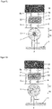
- the fifth arrangement according to the invention Figures 5a and 5b also has the basic structure in the Figures 1a and 1b illustrated embodiment, with the third mass 10 being connected to the first mass 1 via a spring-damper system 11, 12 (second spring-damper system according to the claims) to form an additional oscillatable system 1, 10, 11, 12 (second oscillatable according to the claims). system) is coupled.
- the coupling is designed such that between this spring-damper system 11, 12 and the two masses 1, 10 forces in both directions S1, S2, ie in the direction of gravity as well as against the direction of gravity, are transferrable. Both tensile and compressive forces can therefore be transmitted between the first mass 1 and the third mass 10 via this spring-damper system 11 , 12 .
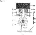
- Figure 5c shows the vibrational model of a sub-variant of the in Figure 5a shown arrangement variant. As can be seen, this differs from the arrangement according to FIG Figure 5a that the second mass 4 is divided here into two partial masses 4a, 4b, which each have their own spring-damper system 5, 6 with the first mass 1 to form an oscillatable system 1, 4a, 5, 6 or 1, 4b , 5, 6 are coupled.
- FIG. 6a and 6b shows the basic structure in the Figures 2a and 2b illustrated embodiment, with the third mass 10 being connected to the first mass 1 via a spring-damper system 11, 12 (second spring-damper system according to the claims) to form an additional oscillatable system 1, 10, 11, 12 (second oscillatable according to the claims). system) is coupled.
- the coupling is designed in such a way that between this spring-damper system 11, 12 and the two masses 1, 10 forces can be transmitted in both directions S1, S2, ie both in the direction of gravity and against the direction of gravity.
- This spring-damper system 11, 12 can therefore be used to transmit both tensile and compressive forces between the first mass 1 and the third mass 10.
- the eighth arrangement according to the invention Figures 8a and 8b differs from that in the Figures 7a and 7b illustrated embodiment only in that the coupling of the third mass 10 and the second mass 4 via the spring-damper system 8a, 9a is realized in such a way that no forces are transmitted via this spring-damper system 8a, 9a in normal operation second mass 4 in the direction S1, ie in the direction of gravity, can be transferred to the third mass 10 and no forces in the direction S2, ie in the direction opposite to the direction of gravity, can be transferred to the second mass 4 from the third mass 10.
- the arrangement is also designed in such a way that this coupling of the two masses 4, 10 via the spring-damper system 8a, 9a can be temporarily canceled during normal operation by an oscillating movement of the second mass 4 in direction S1, i.e. in the direction of gravity , the second mass can then complete part of its oscillation path in the decoupled state, and the coupling of the two masses 4, 10 via the spring-damper system 8a, 9a then after a direction reversal of the oscillation movement of the second mass 4, i.e. during its subsequent movement in the direction S2 against the direction of gravity, is restored.
- FIG. 9 shows the vibrational model of a ninth arrangement according to the invention, its basic structure the Indian Figure 4b illustrated embodiment of the arrangement corresponds.
- the arrangement shown here is part of a hammer drill.
- the contact surface 2, which the first mass 1 makes available here consists of the tip 2 of a drill 14, with which a hole is drilled in a building wall 13, eg made of brick.
- the two directions S1 and S2 run horizontally here, which is why the weight forces of the masses 4, 10 do not generate any coupling or restoring forces and an external force acting on the third mass 10 and in direction S1, ie in the direction of the Building wall to, acting compressive force F is required to ensure the coupling of the second mass 4 to the spring-damper system 5, 6.
- This compressive force F is generated by the operator of the hammer drill.
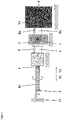
- FIG. 10 shows a side view of a tandem roller according to the invention with an operating weight of approx. 4.5 t.
- the roller has two vibration-excited bandages 1 with smooth outer surfaces 2, which each have an outer diameter of 85 cm.
- the bandage 1 is lined (glued) on the inside with a 1 cm thick mat made of polyurethane 5, 6 with a density of approx. 1.25 g/cm 3 in the area which surrounds the additional mass rings 4a, 4b.
- the mats 5, 6 each form a claimed first spring-damper system for the oscillating coupling of the respective additional mass ring 4a or 4b to the bandage 1.
- the additional mass rings 4a, 4b rest with their weight in the direction of gravity S1 on these mats 5, 6 and are thus on one side via the polyurethane mats 5, 6 coupled to the bandage 1.
- the bandage 1 with the imbalance exciter 7 (first mass according to the claims) has a weight of about 750 kg.
- the additional mass rings 4a, 4b (second mass according to the claims) each have a basic weight of 100 kg and can be loaded with additional weights that can be attached to them in 7.5 kg increments up to a weight of 160 kg each.
- the imbalance exciter 7 comprises a single imbalance shaft 21 (circular vibrator) with a fixed imbalance of about 0.05 kgm, which is mounted in two vertical walls 15a, 15b in the bandage 1 and can be driven in rotation by a hydraulic motor 16.
- the roller chassis 10 (third mass according to the claims) is supported with a weight of about 1100 kg via two arms 17a, 17b, which enter the ends of the drum 1 laterally, on the drum 1, which can be rotated relative to the chassis 10 about a horizontal axis stored around.
- the roller chassis 10 is coupled to the drum 1 via rubber vibration dampers 11, 12, which form a second spring-damper system according to the claims, such that the roller chassis 10 is essentially decoupled from the drum 1 in terms of vibration.
- the bearing is provided by a roller bearing 18, which is rigidly connected to the drum 1, and on the right side by a bearing unit 20 formed by a drum drive motor 19, which is rigidly connected to the right arm 17a of the roller chassis 10 .
- the unbalanced shaft 21 is set in rotation with the hydraulic motor 16 and then generates pulsating excitation forces with a desired excitation frequency (typically in the range between 40 Hz and 100 Hz).
- a desired excitation frequency typically in the range between 40 Hz and 100 Hz.
- the rotational frequency of the imbalance shaft 21 (excitation frequency) and any loading of the additional mass rings 4a, 4b with additional weights are selected in such a way that the additional mass rings 4a, 4b periodically lift off the polyurethane mats 5, 6 in a direction S2 counter to the direction of gravity S1, in this decoupled state perform part of their swing path in this direction S2, and then, after a direction reversal, move again in the direction of gravity S1 and impinge on the polyurethane mats 5, 6 again.
- the outer surface 2 of the bandage 1 remains permanently in contact with the subsoil to be compacted.
- the rotational frequency and any additional weights can vary greatly in order to generate this operating condition.
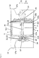
- FIG. 12 shows a vertical section like 11 by an embodiment variant, which differs from that in 11
- the embodiment shown differs only in that instead of the two additional mass rings 4a, 4b arranged in the end regions of the bandage 1, a single additional mass ring 4 (second mass according to the claims) is arranged in the center of the bandage 1, which is vertically freely movable in the bandage 1 and is penetrated by the unbalance shaft 21 of the unbalance exciter 7.
- the vibration engineering model of this variant is in Figure 5a shown.
- the additional mass ring 4 rests with its weight in the direction of gravity S1 on this mat 5, 6 and is thus coupled to the bandage 1 on one side via the polyurethane mat 5, 6.
- the imbalance shaft 21 is set in rotation with the hydraulic motor 16 and the bandage 1 and the additional mass ring 4 are thereby set in motion in such a way that the additional mass ring 4 is periodically lifted off the polyurethane mat 5, 6 in the direction S2 against the direction of gravity S1, in this decoupled state completes part of its oscillation path in this direction S2, and then, after a reversal of direction, moves again in the direction of gravity S1 and hits the polyurethane mat 5, 6 again.
- the rotational frequency of the imbalance shaft can vary greatly in order to generate this operating condition.
- FIG. 13 shows a vertical section like 11 by a further variant, which differs from that in 12 illustrated embodiment differs only in that the additional mass ring 4 has end walls 22a, 22b and the imbalance shaft 21 is not mounted in the two vertical walls 15a, 15b in the bandage 1, but in these end walls 22a, 22b of the additional mass ring 4.
- the unbalanced shaft 21 is coupled to the hydraulic motor 16 via a cardan shaft 23 in such a way that the free vertical mobility of the additional mass ring 4 is not impeded by this coupling.
- the vibration engineering model of this variant is in Figure 5b shown. As can be seen, the imbalance shaft 21 together with the additional mass ring 4 forms the second mass according to the claims.
- the unbalanced shaft 21 is set in rotation with the hydraulic motor 16 and the additional mass ring 4 and the bandage 1 are thereby set in motion in such a way that the additional mass ring 4 with the unbalanced shaft 21 mounted therein periodically moves in the direction S2 against the direction of gravity S1 temporarily from the Polyurethane mat 5, 6 lifts off, in this decoupled state completes part of its oscillation path in this direction S2, and then, after a direction reversal, moves again in the direction of gravity S1 and hits the polyurethane mat 5, 6 again.
- the outer surface 2 of the bandage 1 remains permanently in contact with the subsoil to be compacted.
- the rotational frequency of the unbalanced shaft 21 can also vary greatly here in order to produce this operating state.
Landscapes
- Engineering & Computer Science (AREA)
- Structural Engineering (AREA)
- Life Sciences & Earth Sciences (AREA)
- General Life Sciences & Earth Sciences (AREA)
- Soil Sciences (AREA)
- Environmental & Geological Engineering (AREA)
- Agronomy & Crop Science (AREA)
- Mining & Mineral Resources (AREA)
- Paleontology (AREA)
- Civil Engineering (AREA)
- General Engineering & Computer Science (AREA)
- Vibration Prevention Devices (AREA)
- Road Paving Machines (AREA)
Claims (33)
- Agencement pour fournir une force de compression pulsée, comprenant :a) une première masse (1), qui fournit une surface de contact (2) pour transférer la force de compression pulsée sur un corps (3, 13), en particulier sur une surface de sol (3) à compacter ;b) une deuxième masse (4) ;c) un premier système ressort-amortisseur (5, 6) par lequel la première masse (1) et la deuxième masse (4) sont couplées l'une à l'autre pour former un premier système vibrant (1, 4, 5, 6) ;d) un excitateur de balourd (7) au moyen duquel ce premier système vibrant (1, 4, 5, 6) peut être excité pour vibrer, en particulier pour vibrer en résonance ;dans lequel, à l'état statique du premier système vibrant (1, 4, 5, 6), la deuxième masse (4) exerce une force statique sur la première masse (1) par l'intermédiaire du premier système ressort-amortisseur (5, 6) dans une première direction (S1),
caractérisé en ce quela première masse (1) et la deuxième masse (4) sont couplées l'une à l'autre par l'intermédiaire du premier système ressort-amortisseur (5, 6) de telle sorte que, par l'intermédiaire du premier système ressort-amortisseur (5, 6), dans le fonctionnement prévu, aucune force ne peut être transférée de la première masse (1) dans la première direction (S1) à la deuxième masse (4) et aucune force ne peut être transférée de la deuxième masse (4) dans une deuxième direction (S2), qui est opposée à la première direction (S1), à la première masse (1),et en ce que l'agencement est adapté de telle sorte que le couplage des deux masses (1, 4) via le premier système ressort-amortisseur (5, 6) peut être temporairement suspendu pendant le fonctionnement prévu, en particulier périodiquement, par un mouvement vibratoire de la deuxième masse (4) dans la deuxième direction (S2), en ce que la deuxième masse (4) peut alors effectuer une partie de sa trajectoire d'oscillation à l'état désaccouplé et que le couplage des masses (1, 4) par l'intermédiaire du premier système ressort-amortisseur (5, 6) est ensuite rétabli après une inversion du sens du mouvement vibratoire de la deuxième masse (4), en particulier brusquement. - Agencement selon la revendication 1, dans lequel la première masse (1) et la deuxième masse (4) sont couplées l'une à l'autre par l'intermédiaire du premier système ressort-amortisseur (5, 6) de telle sorte que la deuxième masse (4), lorsqu'elle vibre dans le fonctionnement prévu, peut, en particulier périodiquement, se découpler du premier système ressort-amortisseur (5, 6) par un mouvement dans la deuxième direction (S2) et, à l'état désaccouplé, peut effectuer une partie de sa trajectoire d'oscillation, puis, après une inversion de la direction du mouvement, s'accouple à nouveau au premier système ressort-amortisseur (5, 6), en particulier brusquement.
- Agencement selon l'une des revendications précédentes, dans lequel, à l'état statique du premier système vibrant (1, 4, 5, 6), la deuxième masse (4) exerce une force de compression statique sur la première masse (1) par l'intermédiaire du premier système ressort-amortisseur (5, 6), et dans lequel la première masse (1) et la deuxième masse (4) sont couplées l'une à l'autre par l'intermédiaire du premier système ressort-amortisseur (5, 6) de telle sorte que, par l'intermédiaire du premier système d'amortisseurs à ressort (5, 6), des forces exclusivement compressives peuvent être transférées entre les deux masses (1, 4).
- Agencement selon l'une des revendications 1 à 2, dans lequel, à l'état statique du premier système vibrant, la deuxième masse exerce une force de traction statique sur la première masse (1) par l'intermédiaire du premier système ressort-amortisseur, et dans lequel la première masse et la deuxième masse sont couplées l'une à l'autre par l'intermédiaire du premier système ressort-amortisseur de telle sorte que, par l'intermédiaire du premier système ressort-amortisseur, des forces exclusivement de traction peuvent être transférées entre les deux masses.
- Agencement selon l'une des revendications précédentes, dans lequel la force statique exercée à l'état statique du premier système vibrant (1, 4, 5, 6) par la deuxième masse (4) via le premier système ressort-amortisseur (5, 6) sur la première masse (1) s'étend sensiblement dans le sens de la gravité.
- Agencement selon l'une des revendications précédentes, dans lequel la force statique exercée à l'état statique du premier système vibrant (1, 4, 5, 6) par la deuxième masse (4) via le premier système ressort-amortisseur (5, 6) sur la première masse (1) est en partie ou exclusivement générée par le poids de la deuxième masse (4).
- Agencement selon l'une des revendications précédentes, dans lequel la force statique exercée à l'état statique du premier système vibrant (1, 4, 5, 6) par la deuxième masse (4) via le premier système ressort-amortisseur (5, 6) sur la première masse (1) est générée en partie ou exclusivement par une force agissant sur la deuxième masse (4).
- Agencement selon la revendication 7, dans lequel la force qui agit sur la deuxième masse (4) agit par l'intermédiaire d'un ou plusieurs éléments de ressort (8, 8a) sur la deuxième masse (4).
- Agencement selon la revendication 8, dans lequel le ou les éléments à ressort (8) sont reliés à la première masse (1) de telle sorte qu'à l'état statique du premier système vibrant (1, 4, 5, 6), via ce ou ces éléments à ressort (8), une force est transmise à la première masse (1) qui agit dans la deuxième direction (S2).
- Agencement selon l'une des revendications précédentes, dans lequel la première masse (1) et la deuxième masse (4) sont couplées l'une à l'autre par l'intermédiaire d'un autre système ressort-amortisseur (8, 9), et en particulier, dans lequel le module d'élasticité et/ou l'amortissement de l'autre système ressort-amortisseur (8, 9) est inférieur au module d'élasticité et/ou à l'amortissement du premier système ressort-amortisseur (5, 6).
- Agencement selon la revendication 10, dans lequel la première masse (1) et la deuxième masse (4) sont couplées l'une à l'autre par l'intermédiaire de l'autre système ressort-amortisseur (8, 9) de telle sorte qu'entre l'autre système ressort-amortisseur (8, 9) et les deux masses (1, 4), des forces peuvent être transférées dans la première direction (S1) et dans la deuxième direction (S2).
- Agencement selon la revendication 10, dans lequel la première masse (1) et la deuxième masse (4) sont couplées l'une à l'autre par l'intermédiaire de l'autre système ressort-amortisseur (8, 9) par un couplage unilatéral de telle sorte que par l'intermédiaire de l'autre système ressort-amortisseur (8, 9), dans le fonctionnement prévu, aucune force ne peut être transférée de la deuxième masse (4) dans la première direction (S1) à la première masse (1) et aucune force ne peut être transférée de la première masse (1) dans la deuxième direction (S2) à la deuxième masse (4),
et dans lequel l'agencement est adapté de telle sorte que le couplage des deux masses (1, 4) par l'intermédiaire de l'autre système ressort-amortisseur (8, 9) peut être temporairement suspendu pendant le fonctionnement prévu, en particulier périodiquement, par un mouvement vibratoire de la deuxième masse (4) dans la première direction (S1), la deuxième masse (4) peut alors effectuer une partie de sa trajectoire d'oscillation à l'état désaccouplé, et l'accouplement des deux masses (1, 4) par l'intermédiaire de l'autre système ressort-amortisseur (8, 9) est ensuite rétabli, après une inversion de la direction du mouvement vibratoire de la deuxième masse (4), en particulier brusquement. - Agencement selon la revendication 9 et selon l'une des revendications 10 à 12, dans lequel le ou les éléments de ressort (8), par lesquels la force agit sur la deuxième masse (4), font partie de l'autre système ressort-amortisseur (8, 9).
- Agencement selon l'une des revendications précédentes, dans lequel le dispositif comprend une troisième masse (10) qui est couplée à la première masse (1) par l'intermédiaire d'un deuxième système ressort-amortisseur (11, 12) pour former un deuxième système vibrant (1, 10, 11, 12) et/ou qui est couplée par l'intermédiaire d'un troisième système ressort-amortisseur (8a, 9a) à la deuxième masse (4) pour former un troisième système vibrant (4, 10, 8a, 9a).
- Agencement selon la revendication 14, dans lequel la troisième masse (10) et la première masse (1) sont couplées entre elles par l'intermédiaire d'un deuxième système ressort-amortisseur (11, 12) de telle sorte qu'entre le deuxième système ressort-amortisseur (11, 12) et les deux masses (10, 1), des forces peuvent être transférées dans la première direction (S1) et dans la deuxième direction (S2).
- Agencement selon l'une des revendications 14 à 15, dans lequel la troisième masse (10) et la deuxième masse (4) sont couplées entre elles par l'intermédiaire d'un troisième système ressort-amortisseur (8a, 9a) de telle sorte qu'entre le troisième système ressort-amortisseur (8a, 9a) et les deux masses (10, 4), des forces peuvent être transférées dans la première direction (S1) et dans la deuxième direction (S2) .
- Agencement selon l'une des revendications 14 à 15, dans lequel la troisième masse (10) et la deuxième masse (4) sont couplées l'une à l'autre par l'intermédiaire d'un troisième système ressort-amortisseur (8a, 9a) de telle sorte que, par l'intermédiaire du troisième système ressort-amortisseur (8a, 9a), en fonctionnement prévu, aucune force ne peut être transférée de la deuxième masse (4) dans la première direction (S1) à la troisième masse (10) et aucune force ne peut être transférée de la troisième masse (10) dans la deuxième direction (S2) à la deuxième masse (4),
et dans lequel l'agencement est adapté de telle sorte que le couplage des deux masses (4, 10) via le troisième système ressort-amortisseur (8a, 9a) pendant le fonctionnement prévu peut être temporairement suspendu, en particulier périodiquement, par un mouvement vibratoire de la deuxième masse (4) dans la première direction (S1), la deuxième masse (4) peut alors effectuer une partie de sa trajectoire d'oscillation à l'état découplé, et le couplage des deux masses (4, 10) par l'intermédiaire du troisième système ressort-amortisseur (8a, 9a) est ensuite rétabli après une inversion de la direction du mouvement vibratoire de la deuxième masse (4), en particulier brusquement. - Agencement selon l'une des revendications précédentes, dans lequel les systèmes vibrants (1, 4, 5, 6 ; 1, 10, 11, 12 ; 4, 10, 8a, 9a) sont accordés ou peuvent être accordés de telle sorte que lorsque, dans le fonctionnement prévu de l'agencement, le premier système vibrant (1, 4, 5, 6) vibre, en particulier vibre en résonance, la deuxième masse (4) vibre en phase avec la première masse (1), en particulier avec la fréquence d'oscillation de la première masse (1) ou avec la moitié ou le tiers de la fréquence d'oscillation de la première masse (1).
- Agencement selon l'une des revendications précédentes et selon la revendication 14, dans lequel les systèmes vibrants (1, 4, 5, 6 ; 1, 10, 11, 12 ; 4, 10, 8a, 9a) sont accordés ou peuvent être accordés de telle sorte que lorsque, dans le fonctionnement prévu de l'agencement, le premier système vibrant (1, 4, 5, 6) vibre, en particulier vibre en résonance, la troisième masse (10) n'exécute sensiblement aucun mouvement vibratoire.
- Agencement selon l'une des revendications précédentes, dans lequel l'excitateur de balourd (7) fait partie de la première masse (1) et, dans le fonctionnement prévu, excite ladite masse à vibrer.
- Agencement selon l'une des revendications 1 à 19, dans lequel l'excitateur de balourd (7) fait partie de la deuxième masse (4) et, dans le fonctionnement prévu, excite ladite masse pour la faire vibrer.
- Agencement selon l'une des revendications précédentes, dans lequel l'excitateur de balourd (7) est conçu comme un vibrateur directionnel ou comme un vibrateur circulaire.
- Agencement selon l'une des revendications précédentes, dans lequel la deuxième masse est formée par plusieurs, notamment par exactement deux, notamment des masses partielles identiques (4a, 4b), qui sont couplées chacune par l'intermédiaire d'un premier système ressort-amortisseur propre (5, 6) avec la première masse (1) pour former un premier système vibrant propre (1, 4a, 5, 6 ; 1, 4b, 5, 6).
- Agencement selon l'une des revendications précédentes, dans lequel la surface de contact (2) pour transférer la force de compression pulsée sur un corps (3) qui est fourni par la première masse (1) est la surface extérieure (2) du tambour d'un rouleau, la face inférieure de la plaque inférieure d'une plaque vibrante, la surface de travail (2) d'un outil de burinage ou de forage (14) ou la surface de contact de la plaque vibrante d'un finisseur de route.
- Agencement selon l'une des revendications précédentes, dans lequel la surface de contact (2) pour transférer la force de compression pulsée sur un corps (3) qui est fourni par la première masse (1) est la surface extérieure (2) du tambour d'un rouleau et dans lequel la deuxième masse est formée par un ou plusieurs poids circulaires (4, 4a, 4b) ou comprend de tels poids, qui sont disposés à l'intérieur du tambour (1) et peuvent y exécuter un mouvement vibratoire dans une direction transversale à l'axe longitudinal du tambour (1).
- Agencement selon la revendication 25, dans lequel le poids circulaire (4) ou les poids circulaires est ou sont traversés par l'arbre de balourd (21) de l'excitateur à balourd (7).
- Dispositif de compactage du sol comprenant un agencement selon l'une des revendications précédentes.
- Dispositif de compactage du sol selon la revendication 27, caractérisé en ce qu'il s'agit d'une plaque vibrante ou d'un rouleau, notamment d'un rouleau comportant un ou deux tambours excités par des vibrations.
- Utilisation du dispositif de compactage de sol selon l'une des revendications 27 à 28 pour le compactage d'asphalte.
- Procédé d'opération d'un dispositif selon l'une des revendications 1 à 26 ou d'un dispositif de compactage de sol selon l'une des revendications 27 à 28, dans lequel la surface de contact (2) de la première masse (1) est mise en contact avec un corps (3, 13), en particulier avec une surface de sol (3) à compacter ou avec un corps solide (13) à usiner, et dans lequel le premier système vibrant (1, 4, 5, 6) est excité au moyen de l'excitateur à balourd (7) de manière à vibrer de telle sorte que le couplage des deux masses (1, 4) par l'intermédiaire du premier système ressort-amortisseur (5, 6) est temporairement suspendu pendant le fonctionnement prévu, en particulier périodiquement, par un mouvement vibratoire de la deuxième masse (4) dans la deuxième direction (S2), la deuxième masse (4) exécute alors une partie de son trajet d'oscillation à l'état désaccouplé, et le couplage des masses (1, 4) par l'intermédiaire du premier système ressort-amortisseur (5, 6) est ensuite rétabli après une inversion du sens du mouvement vibratoire de la deuxième masse (4), en particulier brusquement.
- Procédé selon la revendication 30, dans lequel la surface de contact (2) de la première masse (1) est maintenue en permanence en contact avec le corps (3, 13) .
- Procédé selon l'une des revendications 30 à 31, dans lequel les systèmes vibrants (1, 4, 5, 6 ; 1, 10, 11, 12 ; 4, 10, 8a, 9a) de l'agencement sont excités pour vibrer de telle sorte que la deuxième masse (4) vibre en phase avec la première masse (1), notamment avec la fréquence d'oscillation de la première masse (1) ou avec la moitié ou le tiers de la fréquence d'oscillation de la première masse (1).
- Procédé selon l'une des revendications 30 à 32, dans lequel on utilise un dispositif selon la revendication 19 et, ce faisant, on excite en vibration les systèmes vibrants (1, 4, 5, 6 ; 1, 10, 11, 12 ; 4, 10, 8a, 9a) du dispositif de telle sorte que la troisième masse (10) n'exécute sensiblement aucun mouvement vibratoire.
Applications Claiming Priority (1)
| Application Number | Priority Date | Filing Date | Title |
|---|---|---|---|
| PCT/CH2015/000178 WO2017091912A1 (fr) | 2015-12-03 | 2015-12-03 | Agencement pour produire une force de compression pulsée |
Publications (2)
| Publication Number | Publication Date |
|---|---|
| EP3384096A1 EP3384096A1 (fr) | 2018-10-10 |
| EP3384096B1 true EP3384096B1 (fr) | 2022-08-03 |
Family
ID=54883935
Family Applications (1)
| Application Number | Title | Priority Date | Filing Date |
|---|---|---|---|
| EP15812936.1A Active EP3384096B1 (fr) | 2015-12-03 | 2015-12-03 | Agencement pour produire une force de compression pulsée |
Country Status (6)
| Country | Link |
|---|---|
| US (1) | US10428482B2 (fr) |
| EP (1) | EP3384096B1 (fr) |
| JP (1) | JP2018536106A (fr) |
| AU (1) | AU2015416104A1 (fr) |
| CA (1) | CA3006611A1 (fr) |
| WO (1) | WO2017091912A1 (fr) |
Families Citing this family (1)
| Publication number | Priority date | Publication date | Assignee | Title |
|---|---|---|---|---|
| DE102019132917A1 (de) * | 2019-12-04 | 2021-06-10 | Hamm Ag | Bodenbearbeitungswalze |
Family Cites Families (5)
| Publication number | Priority date | Publication date | Assignee | Title |
|---|---|---|---|---|
| US6742960B2 (en) * | 2002-07-09 | 2004-06-01 | Caterpillar Inc. | Vibratory compactor and method of using same |
| DE202004014585U1 (de) * | 2004-09-16 | 2006-01-26 | Weber Maschinentechnik Gmbh | Schwingungserreger |
| DE202009004302U1 (de) * | 2008-04-01 | 2009-11-12 | Wacker Neuson Se | Vibrationsplatte mit Zwischenmasse |
| EP2558649B1 (fr) | 2010-04-16 | 2014-11-19 | Ammann Schweiz AG | Agencement pour fournir une force de pression pulsée |
| US8608403B2 (en) * | 2012-03-28 | 2013-12-17 | Caterpillar Paving Products Inc. | Magnetic vibratory compactor |
-
2015
- 2015-12-03 WO PCT/CH2015/000178 patent/WO2017091912A1/fr not_active Ceased
- 2015-12-03 JP JP2018548249A patent/JP2018536106A/ja active Pending
- 2015-12-03 CA CA3006611A patent/CA3006611A1/fr not_active Abandoned
- 2015-12-03 EP EP15812936.1A patent/EP3384096B1/fr active Active
- 2015-12-03 AU AU2015416104A patent/AU2015416104A1/en not_active Abandoned
- 2015-12-03 US US15/780,316 patent/US10428482B2/en active Active
Also Published As
| Publication number | Publication date |
|---|---|
| CA3006611A1 (fr) | 2017-06-08 |
| US20180355572A1 (en) | 2018-12-13 |
| EP3384096A1 (fr) | 2018-10-10 |
| AU2015416104A1 (en) | 2018-06-14 |
| WO2017091912A1 (fr) | 2017-06-08 |
| JP2018536106A (ja) | 2018-12-06 |
| US10428482B2 (en) | 2019-10-01 |
Similar Documents
| Publication | Publication Date | Title |
|---|---|---|
| EP2558649B1 (fr) | Agencement pour fournir une force de pression pulsée | |
| EP0116164B1 (fr) | Appareil de battage par vibration | |
| EP3951057A1 (fr) | Système de rouleau de traitement du sol pour une machine de traitement du sol | |
| EP2732100B1 (fr) | Excitateur à balourd pour compacteur de sol | |
| DE69732665T2 (de) | Vibratoradapter | |
| EP2781269A1 (fr) | Générateur de vibrations, notamment pour une machine de construction | |
| EP1632637B1 (fr) | Outil de travail du sol et procédé pour introduire un élément de travail dans le sol | |
| DE3743817C2 (de) | Gesteins-, Bohr- und Meisselwerkzeug | |
| EP3450631B1 (fr) | Vibreur en profondeur avec une masse non équilibrée réglable | |
| DE102019124415A1 (de) | Unwuchtsystem mit reduzierter rotationsträgheit für vibrationsverdichter | |
| DE69908199T2 (de) | Schwingförderer mit seitlich montierten Antriebsgeräten | |
| EP2242590B1 (fr) | Excitateur à balourds comprenant un ou plusieurs balourds rotatifs | |
| EP3384096B1 (fr) | Agencement pour produire une force de compression pulsée | |
| WO2016102432A1 (fr) | Vibreur en profondeur | |
| EP2365132A2 (fr) | Vibrateur manuel pour compacter des matériaux dans la construction de routes, de voies ferrées et de terrassements | |
| EP3237687B1 (fr) | Amortisseur de vibrations pour articulation d'accouplement d'un dispositif de vibration en profondeur | |
| DE3786067T2 (de) | Vorrichtung zum Zerbrechen einer Fläche. | |
| EP3165290B1 (fr) | Dispositif de production de vibrations et procede d'introduction de profile dans un sol | |
| WO2018098599A1 (fr) | Procédé et dispositif d'enlèvement par fraisage des matériaux rocheux ou des matériaux de type roche | |
| DE102005024367A1 (de) | Seismische Quelle und Verfahren zur Erzeugung seismischer Scherwellen | |
| DE102004014722B3 (de) | Seismische Quelle und Verfahren zur Erzeugung seismischer Schwingungen | |
| DE2219819C3 (de) | Drehbohrgerät | |
| DE102012222757A1 (de) | Verdichtungsgerät zum Verdichten von Böden sowie Verfahren zum Verdichten von Böden | |
| DE1058931B (de) | Schwingfoerder- und/oder Siebvorrichtung | |
| DE202005006350U1 (de) | Bodenverdichter |
Legal Events
| Date | Code | Title | Description |
|---|---|---|---|
| STAA | Information on the status of an ep patent application or granted ep patent |
Free format text: STATUS: THE INTERNATIONAL PUBLICATION HAS BEEN MADE |
|
| PUAI | Public reference made under article 153(3) epc to a published international application that has entered the european phase |
Free format text: ORIGINAL CODE: 0009012 |
|
| STAA | Information on the status of an ep patent application or granted ep patent |
Free format text: STATUS: REQUEST FOR EXAMINATION WAS MADE |
|
| 17P | Request for examination filed |
Effective date: 20180515 |
|
| AK | Designated contracting states |
Kind code of ref document: A1 Designated state(s): AL AT BE BG CH CY CZ DE DK EE ES FI FR GB GR HR HU IE IS IT LI LT LU LV MC MK MT NL NO PL PT RO RS SE SI SK SM TR |
|
| AX | Request for extension of the european patent |
Extension state: BA ME |
|
| DAV | Request for validation of the european patent (deleted) | ||
| DAX | Request for extension of the european patent (deleted) | ||
| STAA | Information on the status of an ep patent application or granted ep patent |
Free format text: STATUS: EXAMINATION IS IN PROGRESS |
|
| 17Q | First examination report despatched |
Effective date: 20190826 |
|
| GRAP | Despatch of communication of intention to grant a patent |
Free format text: ORIGINAL CODE: EPIDOSNIGR1 |
|
| STAA | Information on the status of an ep patent application or granted ep patent |
Free format text: STATUS: GRANT OF PATENT IS INTENDED |
|
| INTG | Intention to grant announced |
Effective date: 20220301 |
|
| GRAS | Grant fee paid |
Free format text: ORIGINAL CODE: EPIDOSNIGR3 |
|
| GRAA | (expected) grant |
Free format text: ORIGINAL CODE: 0009210 |
|
| STAA | Information on the status of an ep patent application or granted ep patent |
Free format text: STATUS: THE PATENT HAS BEEN GRANTED |
|
| AK | Designated contracting states |
Kind code of ref document: B1 Designated state(s): AL AT BE BG CH CY CZ DE DK EE ES FI FR GB GR HR HU IE IS IT LI LT LU LV MC MK MT NL NO PL PT RO RS SE SI SK SM TR |
|
| REG | Reference to a national code |
Ref country code: AT Ref legal event code: REF Ref document number: 1508847 Country of ref document: AT Kind code of ref document: T Effective date: 20220815 Ref country code: CH Ref legal event code: EP |
|
| REG | Reference to a national code |
Ref country code: DE Ref legal event code: R096 Ref document number: 502015015993 Country of ref document: DE |
|
| REG | Reference to a national code |
Ref country code: IE Ref legal event code: FG4D Free format text: LANGUAGE OF EP DOCUMENT: GERMAN |
|
| REG | Reference to a national code |
Ref country code: NL Ref legal event code: FP |
|
| REG | Reference to a national code |
Ref country code: SE Ref legal event code: TRGR |
|
| REG | Reference to a national code |
Ref country code: LT Ref legal event code: MG9D |
|
| PG25 | Lapsed in a contracting state [announced via postgrant information from national office to epo] |
Ref country code: RS Free format text: LAPSE BECAUSE OF FAILURE TO SUBMIT A TRANSLATION OF THE DESCRIPTION OR TO PAY THE FEE WITHIN THE PRESCRIBED TIME-LIMIT Effective date: 20220803 Ref country code: PT Free format text: LAPSE BECAUSE OF FAILURE TO SUBMIT A TRANSLATION OF THE DESCRIPTION OR TO PAY THE FEE WITHIN THE PRESCRIBED TIME-LIMIT Effective date: 20221205 Ref country code: NO Free format text: LAPSE BECAUSE OF FAILURE TO SUBMIT A TRANSLATION OF THE DESCRIPTION OR TO PAY THE FEE WITHIN THE PRESCRIBED TIME-LIMIT Effective date: 20221103 Ref country code: LV Free format text: LAPSE BECAUSE OF FAILURE TO SUBMIT A TRANSLATION OF THE DESCRIPTION OR TO PAY THE FEE WITHIN THE PRESCRIBED TIME-LIMIT Effective date: 20220803 Ref country code: LT Free format text: LAPSE BECAUSE OF FAILURE TO SUBMIT A TRANSLATION OF THE DESCRIPTION OR TO PAY THE FEE WITHIN THE PRESCRIBED TIME-LIMIT Effective date: 20220803 Ref country code: FI Free format text: LAPSE BECAUSE OF FAILURE TO SUBMIT A TRANSLATION OF THE DESCRIPTION OR TO PAY THE FEE WITHIN THE PRESCRIBED TIME-LIMIT Effective date: 20220803 Ref country code: ES Free format text: LAPSE BECAUSE OF FAILURE TO SUBMIT A TRANSLATION OF THE DESCRIPTION OR TO PAY THE FEE WITHIN THE PRESCRIBED TIME-LIMIT Effective date: 20220803 |
|
| PG25 | Lapsed in a contracting state [announced via postgrant information from national office to epo] |
Ref country code: PL Free format text: LAPSE BECAUSE OF FAILURE TO SUBMIT A TRANSLATION OF THE DESCRIPTION OR TO PAY THE FEE WITHIN THE PRESCRIBED TIME-LIMIT Effective date: 20220803 Ref country code: IS Free format text: LAPSE BECAUSE OF FAILURE TO SUBMIT A TRANSLATION OF THE DESCRIPTION OR TO PAY THE FEE WITHIN THE PRESCRIBED TIME-LIMIT Effective date: 20221203 Ref country code: HR Free format text: LAPSE BECAUSE OF FAILURE TO SUBMIT A TRANSLATION OF THE DESCRIPTION OR TO PAY THE FEE WITHIN THE PRESCRIBED TIME-LIMIT Effective date: 20220803 Ref country code: GR Free format text: LAPSE BECAUSE OF FAILURE TO SUBMIT A TRANSLATION OF THE DESCRIPTION OR TO PAY THE FEE WITHIN THE PRESCRIBED TIME-LIMIT Effective date: 20221104 |
|
| PG25 | Lapsed in a contracting state [announced via postgrant information from national office to epo] |
Ref country code: SM Free format text: LAPSE BECAUSE OF FAILURE TO SUBMIT A TRANSLATION OF THE DESCRIPTION OR TO PAY THE FEE WITHIN THE PRESCRIBED TIME-LIMIT Effective date: 20220803 Ref country code: RO Free format text: LAPSE BECAUSE OF FAILURE TO SUBMIT A TRANSLATION OF THE DESCRIPTION OR TO PAY THE FEE WITHIN THE PRESCRIBED TIME-LIMIT Effective date: 20220803 Ref country code: DK Free format text: LAPSE BECAUSE OF FAILURE TO SUBMIT A TRANSLATION OF THE DESCRIPTION OR TO PAY THE FEE WITHIN THE PRESCRIBED TIME-LIMIT Effective date: 20220803 Ref country code: CZ Free format text: LAPSE BECAUSE OF FAILURE TO SUBMIT A TRANSLATION OF THE DESCRIPTION OR TO PAY THE FEE WITHIN THE PRESCRIBED TIME-LIMIT Effective date: 20220803 |
|
| REG | Reference to a national code |
Ref country code: DE Ref legal event code: R097 Ref document number: 502015015993 Country of ref document: DE |
|
| PG25 | Lapsed in a contracting state [announced via postgrant information from national office to epo] |
Ref country code: SK Free format text: LAPSE BECAUSE OF FAILURE TO SUBMIT A TRANSLATION OF THE DESCRIPTION OR TO PAY THE FEE WITHIN THE PRESCRIBED TIME-LIMIT Effective date: 20220803 Ref country code: EE Free format text: LAPSE BECAUSE OF FAILURE TO SUBMIT A TRANSLATION OF THE DESCRIPTION OR TO PAY THE FEE WITHIN THE PRESCRIBED TIME-LIMIT Effective date: 20220803 |
|
| PLBE | No opposition filed within time limit |
Free format text: ORIGINAL CODE: 0009261 |
|
| STAA | Information on the status of an ep patent application or granted ep patent |
Free format text: STATUS: NO OPPOSITION FILED WITHIN TIME LIMIT |
|
| P01 | Opt-out of the competence of the unified patent court (upc) registered |
Effective date: 20230516 |
|
| PG25 | Lapsed in a contracting state [announced via postgrant information from national office to epo] |
Ref country code: AL Free format text: LAPSE BECAUSE OF FAILURE TO SUBMIT A TRANSLATION OF THE DESCRIPTION OR TO PAY THE FEE WITHIN THE PRESCRIBED TIME-LIMIT Effective date: 20220803 |
|
| 26N | No opposition filed |
Effective date: 20230504 |
|
| PG25 | Lapsed in a contracting state [announced via postgrant information from national office to epo] |
Ref country code: SI Free format text: LAPSE BECAUSE OF FAILURE TO SUBMIT A TRANSLATION OF THE DESCRIPTION OR TO PAY THE FEE WITHIN THE PRESCRIBED TIME-LIMIT Effective date: 20220803 Ref country code: LU Free format text: LAPSE BECAUSE OF NON-PAYMENT OF DUE FEES Effective date: 20221203 |
|
| PG25 | Lapsed in a contracting state [announced via postgrant information from national office to epo] |
Ref country code: IE Free format text: LAPSE BECAUSE OF NON-PAYMENT OF DUE FEES Effective date: 20221203 |
|
| PGFP | Annual fee paid to national office [announced via postgrant information from national office to epo] |
Ref country code: GB Payment date: 20231220 Year of fee payment: 9 |
|
| PGFP | Annual fee paid to national office [announced via postgrant information from national office to epo] |
Ref country code: SE Payment date: 20231220 Year of fee payment: 9 Ref country code: NL Payment date: 20231220 Year of fee payment: 9 Ref country code: FR Payment date: 20231222 Year of fee payment: 9 Ref country code: AT Payment date: 20231221 Year of fee payment: 9 |
|
| PGFP | Annual fee paid to national office [announced via postgrant information from national office to epo] |
Ref country code: BE Payment date: 20231220 Year of fee payment: 9 |
|
| PG25 | Lapsed in a contracting state [announced via postgrant information from national office to epo] |
Ref country code: HU Free format text: LAPSE BECAUSE OF FAILURE TO SUBMIT A TRANSLATION OF THE DESCRIPTION OR TO PAY THE FEE WITHIN THE PRESCRIBED TIME-LIMIT; INVALID AB INITIO Effective date: 20151203 |
|
| PG25 | Lapsed in a contracting state [announced via postgrant information from national office to epo] |
Ref country code: CY Free format text: LAPSE BECAUSE OF FAILURE TO SUBMIT A TRANSLATION OF THE DESCRIPTION OR TO PAY THE FEE WITHIN THE PRESCRIBED TIME-LIMIT Effective date: 20220803 |
|
| PGFP | Annual fee paid to national office [announced via postgrant information from national office to epo] |
Ref country code: CH Payment date: 20240102 Year of fee payment: 9 |
|
| PG25 | Lapsed in a contracting state [announced via postgrant information from national office to epo] |
Ref country code: MK Free format text: LAPSE BECAUSE OF FAILURE TO SUBMIT A TRANSLATION OF THE DESCRIPTION OR TO PAY THE FEE WITHIN THE PRESCRIBED TIME-LIMIT Effective date: 20220803 Ref country code: IT Free format text: LAPSE BECAUSE OF FAILURE TO SUBMIT A TRANSLATION OF THE DESCRIPTION OR TO PAY THE FEE WITHIN THE PRESCRIBED TIME-LIMIT Effective date: 20220803 |
|
| PG25 | Lapsed in a contracting state [announced via postgrant information from national office to epo] |
Ref country code: MC Free format text: LAPSE BECAUSE OF FAILURE TO SUBMIT A TRANSLATION OF THE DESCRIPTION OR TO PAY THE FEE WITHIN THE PRESCRIBED TIME-LIMIT Effective date: 20220803 |
|
| PG25 | Lapsed in a contracting state [announced via postgrant information from national office to epo] |
Ref country code: MC Free format text: LAPSE BECAUSE OF FAILURE TO SUBMIT A TRANSLATION OF THE DESCRIPTION OR TO PAY THE FEE WITHIN THE PRESCRIBED TIME-LIMIT Effective date: 20220803 |
|
| PG25 | Lapsed in a contracting state [announced via postgrant information from national office to epo] |
Ref country code: BG Free format text: LAPSE BECAUSE OF FAILURE TO SUBMIT A TRANSLATION OF THE DESCRIPTION OR TO PAY THE FEE WITHIN THE PRESCRIBED TIME-LIMIT Effective date: 20220803 |
|
| PG25 | Lapsed in a contracting state [announced via postgrant information from national office to epo] |
Ref country code: MT Free format text: LAPSE BECAUSE OF FAILURE TO SUBMIT A TRANSLATION OF THE DESCRIPTION OR TO PAY THE FEE WITHIN THE PRESCRIBED TIME-LIMIT Effective date: 20220803 |
|
| REG | Reference to a national code |
Ref country code: SE Ref legal event code: EUG |
|
| REG | Reference to a national code |
Ref country code: CH Ref legal event code: PL |
|
| REG | Reference to a national code |
Ref country code: NL Ref legal event code: MM Effective date: 20250101 |
|
| REG | Reference to a national code |
Ref country code: AT Ref legal event code: MM01 Ref document number: 1508847 Country of ref document: AT Kind code of ref document: T Effective date: 20241203 |
|
| GBPC | Gb: european patent ceased through non-payment of renewal fee |
Effective date: 20241203 |
|
| PG25 | Lapsed in a contracting state [announced via postgrant information from national office to epo] |
Ref country code: NL Free format text: LAPSE BECAUSE OF NON-PAYMENT OF DUE FEES Effective date: 20250101 |
|
| REG | Reference to a national code |
Ref country code: BE Ref legal event code: MM Effective date: 20241231 |
|
| PG25 | Lapsed in a contracting state [announced via postgrant information from national office to epo] |
Ref country code: GB Free format text: LAPSE BECAUSE OF NON-PAYMENT OF DUE FEES Effective date: 20241203 Ref country code: BE Free format text: LAPSE BECAUSE OF NON-PAYMENT OF DUE FEES Effective date: 20241231 |
|
| PG25 | Lapsed in a contracting state [announced via postgrant information from national office to epo] |
Ref country code: AT Free format text: LAPSE BECAUSE OF NON-PAYMENT OF DUE FEES Effective date: 20241203 Ref country code: FR Free format text: LAPSE BECAUSE OF NON-PAYMENT OF DUE FEES Effective date: 20241231 |
|
| PG25 | Lapsed in a contracting state [announced via postgrant information from national office to epo] |
Ref country code: CH Free format text: LAPSE BECAUSE OF NON-PAYMENT OF DUE FEES Effective date: 20241231 |
|
| PG25 | Lapsed in a contracting state [announced via postgrant information from national office to epo] |
Ref country code: TR Free format text: LAPSE BECAUSE OF FAILURE TO SUBMIT A TRANSLATION OF THE DESCRIPTION OR TO PAY THE FEE WITHIN THE PRESCRIBED TIME-LIMIT Effective date: 20220803 |
|
| PGFP | Annual fee paid to national office [announced via postgrant information from national office to epo] |
Ref country code: DE Payment date: 20251211 Year of fee payment: 11 |