EP3384126B1 - Ensemble vanne - Google Patents
Ensemble vanne Download PDFInfo
- Publication number
- EP3384126B1 EP3384126B1 EP16816333.5A EP16816333A EP3384126B1 EP 3384126 B1 EP3384126 B1 EP 3384126B1 EP 16816333 A EP16816333 A EP 16816333A EP 3384126 B1 EP3384126 B1 EP 3384126B1
- Authority
- EP
- European Patent Office
- Prior art keywords
- valve
- housing
- assembly
- valve assembly
- valve member
- Prior art date
- Legal status (The legal status is an assumption and is not a legal conclusion. Google has not performed a legal analysis and makes no representation as to the accuracy of the status listed.)
- Active
Links
Images









Classifications
-
- E—FIXED CONSTRUCTIONS
- E21—EARTH OR ROCK DRILLING; MINING
- E21B—EARTH OR ROCK DRILLING; OBTAINING OIL, GAS, WATER, SOLUBLE OR MELTABLE MATERIALS OR A SLURRY OF MINERALS FROM WELLS
- E21B34/00—Valve arrangements for boreholes or wells
- E21B34/06—Valve arrangements for boreholes or wells in wells
- E21B34/12—Valve arrangements for boreholes or wells in wells operated by movement of casings or tubings
-
- E—FIXED CONSTRUCTIONS
- E21—EARTH OR ROCK DRILLING; MINING
- E21B—EARTH OR ROCK DRILLING; OBTAINING OIL, GAS, WATER, SOLUBLE OR MELTABLE MATERIALS OR A SLURRY OF MINERALS FROM WELLS
- E21B21/00—Methods or apparatus for flushing boreholes, e.g. by use of exhaust air from motor
- E21B21/10—Valve arrangements in drilling-fluid circulation systems
-
- E—FIXED CONSTRUCTIONS
- E21—EARTH OR ROCK DRILLING; MINING
- E21B—EARTH OR ROCK DRILLING; OBTAINING OIL, GAS, WATER, SOLUBLE OR MELTABLE MATERIALS OR A SLURRY OF MINERALS FROM WELLS
- E21B34/00—Valve arrangements for boreholes or wells
- E21B34/06—Valve arrangements for boreholes or wells in wells
- E21B34/10—Valve arrangements for boreholes or wells in wells operated by control fluid supplied from outside the borehole
-
- E—FIXED CONSTRUCTIONS
- E21—EARTH OR ROCK DRILLING; MINING
- E21B—EARTH OR ROCK DRILLING; OBTAINING OIL, GAS, WATER, SOLUBLE OR MELTABLE MATERIALS OR A SLURRY OF MINERALS FROM WELLS
- E21B41/00—Equipment or details not covered by groups E21B15/00 - E21B40/00
-
- E—FIXED CONSTRUCTIONS
- E21—EARTH OR ROCK DRILLING; MINING
- E21B—EARTH OR ROCK DRILLING; OBTAINING OIL, GAS, WATER, SOLUBLE OR MELTABLE MATERIALS OR A SLURRY OF MINERALS FROM WELLS
- E21B2200/00—Special features related to earth drilling for obtaining oil, gas or water
- E21B2200/05—Flapper valves
Definitions
- the present invention relates to apparatus and a method relating to a valve assembly and a method of controlling flow in an oil or gas well.
- Non-return valves are known in the art to control fluid flow in a conduit, permitting fluid flow in one direction, and restricting or preventing it in another direction.
- NRVs are used in oil and gas well conduits for preventing backflow of drilling mud up an oil or gas wellbore or drill string.
- NRVs are frequently in the form of flapper valves comprising a pivot pin positioned in a hole drilled through a pivot tongue in the valve body, with a torsion spring wrapped around the pivot pin to offer some resilience in the flapper movement.
- US Patent number 4,248,264 discloses an internal mud saver valve that uses a flapper spring located on a pivot pin arrangement to shut a flapper valve.
- valve assembly for controlling fluid flow in a throughbore of a wellbore conduit of an oil, gas or water well, the assembly comprising:-
- the present invention further provides a method of control of fluid flow in a throughbore of a wellbore conduit of an oil, gas or water well, the method including flowing the fluid through a valve disposed in a body being in fluid communication with the wellbore conduit, the valve comprising at least one valve member disposed in a valve housing, wherein the housing is axially movable with respect to the body, and wherein a displacement mechanism is configured to urge the valve housing to move in an axial direction with respect to the body, wherein axial movement of the housing with respect to the body actuates the valve member between an open configuration and a closed configuration, and wherein the valve is adapted to be opened by a pressure differential, arising from flow of fluid in the throughbore in an uphole to downhole direction, acting across the valve, wherein the displacement mechanism is configured to urge the valve member into the closed configuration; wherein the valve assembly includes a valve control member adapted to control axial movement of the valve housing in the body; characterised by the valve assembly incorporating a radial offset between a
- valve assembly 1 used in an NRV tool in accordance with the present invention is shown as comprising a valve disposed within a valve body 5v.
- the valve body 5v is a part of a larger tool shown in full in figures 11-18 , comprising a tool body 5 made up of an upper body 5u with a female box connector at its upper end for making up the tool into a string for use in a wellbore, an actuator body 5a comprising an actuator assembly that will be described in detail below, a central body 5c connecting the actuator assembly to the valve assembly 1, and a lower body 5l below the valve assembly 1, having a male pin connector or similar for making the tool up into a string.
- box connector of the upper body 5u is located at the, in use, uppermost end of the NRV tool and the pin connector of the lower body 5l is located at the, in use, lowermost end of the NRV tool.
- the valve in the valve body 5v comprises a valve cartridge 10 having a valve member in the form of a flapper 14, with the flapper 14 disposed in a housing 11, the housing 11 having a central bore 11b which is coaxial and in communication with the bore 5b of the valve body 5v.
- the assembly 1 has two valve cartridges 10 arranged and in this example connected axially together in series by a narrowed lower section of the head of the upper cartridge 10 to the left hand side of figure 1 . More than one valve cartridge 10 per valve assembly 1 is not necessary, but offers the advantage of redundancy in the event of failure of one of the valves. Interconnection of the cartridges 10 is also unnecessary, but optionally assists with movement of the valves in concert.
- each cartridge 10 is adapted to move axially within the valve body 5v. Where two or more cartridges 10 are connected in series, as shown in figure 1 , the cartridges 10 optionally move axially together as a single unit.
- the valve assembly 1 further comprises a displacement mechanism, here in the form of a coiled spring 12, positioned outside of the fluid flowpath and axially aligned with the valve assembly 1.
- the spring 12 is axially spaced from the flapper 14 and has a wide coil diameter with a large axial bore that allows the body of the spring 12 to be radially spaced from the throughbore of the valve body 5v.
- the spring 12 engages with the end face of the housing 11 on a circumference of the housing 11, radially close to the outer edge of the housing 11, via a spring sleeve 12s, which centralises the lower end of the lowermost valve within the bore of the valve body 5v.
- the spring sleeve 12s has a top hat structure with an axial bore which receives (at its upper end) the lower end of the housing 11.
- At the lower end of the spring sleeve 12s there is an annular plate presenting a flat surface for engaging the spring, and having a central aperture coaxial with the bore 11b (and no narrower than the bore 11b) to permit axial passage of fluids and equipment through the valve assembly.
- the spring 12 acts to urge the housing 11 axially within the valve body 5v, and is normally maintained in compression between the housing 11 and a shoulder (normally facing uphole) in the bore of the valve body 5v below the valves, hence urges the valves uphole in the valve body 5v.
- the spring 12 being sited outside of the fluid flowpath increases reliability and reduces turbulence through the valve.
- the spring 12 dimensions and spring rate of the spring 12 can be adapted within very wide parameters to suit the requirements of the valve assembly without compromising other aspect of the valve performance.
- the spring 12 has a wide diameter, acting around the circumference of the housing 11 via the spring sleeve 12s, is relatively long, and can optionally exert a relatively large axial force on the housing 11, and thus on the flapper 14.
- the flapper 14 will start to close at lower flow rates. In this example, the flapper 14 will close only in the absence of flow of fluid from above the valve.
- the valve assembly 1 has a valve control member in the form of a valve control member or activation ring 20 which extends radially into the bore 5b of the valve body 5v, and acts to control the actuation status of the valve by relative movement of the activation ring and the valve.
- the activation ring 20 is optionally resiliently biased in a radial direction, and in this example, the activation ring 20 is resiliently biased radially outward from the axis of the bore 5b. In this example, the activation ring 20 remains static within the valve body 5v, and the axial movement of the housing 11 within the valve body 5v relative to the activation ring 20 actuates the flapper 14 between an open configuration and a closed configuration.
- the flapper 14 When in the closed configuration as shown in Figure 1 , the flapper 14 is seated against chamfered or tapered edges of the housing 11 set at an angle to the axis of the bore and forming a valve seat at the downhole portion of the neck of the housing 11, and forming a metal-to-metal seal across the valve when the valve is closed.
- the tapered edges also contain a bonded seal 17, partially recessed in a groove within the chamfered surface of the seat, and largely protected from fluid flowing through the valve from uphole to downhole.
- the housing 11 further has tapered edges at the uphole side of its neck portion, acting as an initial funnel of the fluid flow into the valve.
- the downhole chamfered edges diverge in an axial direction and thus protect the bonded seal 17 from the majority of the force of the fluid, which reduces in pressure as it passes through the neck of the valve seat when the valve is open.
- the flapper 14 is pivotally connected to the housing 11 by a pivot that is integral to one of the valve member and the housing.
- the pivot comprises a pivot axle integral with the flapper 14 and extending in a perpendicular direction from opposing parallel side faces of a neck of the flapper 14, and an axle-receiving recess on the housing 11.
- the flapper 14 is therefore pivotally coupled to the valve housing 11 by a pivot axle formed as an integral part of the flapper 14 received within a groove formed in the valve housing 11.
- This arrangement avoids drilling holes through the flapper and housing and allows a stronger construction. Since no torsion spring needs to be accommodated between the flapper and the housing the tolerances between the two can be precise.
- the groove on the housing resiliently retains the integral pivot axle of the flapper, and resists separation of the two components in normal use.
- the flapper is able to move passively in a pivot arc around the axle with respect to the valve housing 11.
- the spring 12 effectively replaces the conventional torsion spring wound around a pivot pin that is conventionally used in flapper valves. These springs and pins represent a high fatigue failure risk as they are positioned in the fluid flowpath, which also increases turbulence and erosion in the region of the flapper.
- An upper face of an outer diameter of the activation ring 20 engages with a downwardly facing shoulder in a groove 5g on the inner diameter of the valve body 5v, resisting axial travel of the activation ring up the bore of the valve body 5v.
- the activation ring 20 can travel down the groove 5g, but is biased against the downwardly facing shoulder at the upper end of the groove 5g by the spring 12, held in compression below the valve.
- the flapper 14 has a plate extending from the pivot axis 13 at the neck to engage the seat and close the valve as previously mentioned, and the plate extends away from the pivot axis in one direction (radially inwards from the pivot axis 13 when the valve is closed as in figure 1 ).
- the neck of the flapper 14 also has a tang having a flat faced shoulder 14s extending away from the pivot axis 13 in the same plane as the plate of the flapper 14, but in the opposite direction (radially outwards from the pivot axis13 when the valve is closed).
- the flat face of the shoulder 14s on the flapper behind the pivot axis 13 therefore extends radially outwards from the pivot axis 13 in a radial direction with respect to the axis of the bore 11b beyond the radial position of the pivot axis 13, so that the outer edge of the flat faced shoulder 14s is offset from the pivot axis 13 in a radial direction with respect to the axis of the bore 5b.
- the activation ring 20 cannot move up in the bore 5b of the body, as it is pressed (by the spring 12) against the downwardly facing shoulder at the upper end of the groove 5g, so the interaction of the shoulder 14s on the flapper with the lower face of the activation ring 20 urges pivotal movement of the flapper 14 as a whole around the pivot axis 13 and ultimately presses the flapper plate against the seat, closing the valve.
- the flapper 14 is restrained against rotation around the pivot axis 13 to open the valve when the flat upper face of the shoulder 14s is engaged with the flat lower face of the activation ring 20.
- the flapper 14 can be opened by a hydraulic or mechanically applied load from above urging the upper face of the flapper downwards, which initiates movement of the flapper 14 to unseat it from the housing 11 and from the activation ring 20, allowing rotation of the flapper 14 around the pivot axis 13 to open the valve.
- the closed configuration as shown in figure 1 is the normal resting position.
- the spring 12 is compressed between an upwardly-facing end of the lower body 5l below the valve body 5v and the spring sleeve 12s engaging the lower end of the lower valve cartridge 10.
- the compression force of the spring 12 pushes the housing 11 of each of the valves upwards in the bore.
- the force of the compression spring 12 also urges the valves into the closed configuration from an open configuration, as the upward movement of the valve housings 11 in the bore under the force of the spring 12 pivots the flapper 14 around the pivot axis 13 as the inner edge of the activation ring 20 engages with a flat end face 14e on the shoulder 14s at a radial position that is offset from the pivot axis of the flapper 14, to rotate the flapper 14 around the pivot axis 13 into the closed configuration shown in figure 1 .
- the cartridge 10 travels axially in the downhole direction and overcomes the force applied by the spring 12, for example under the force of a fluid pressure differential from high pressure above the valve, to low pressure below it.
- a key 22 in the form of an axial ridge is positioned on the housing 11 to occupy a space between the ends of the activation ring 20 and thereby prevent it from rotating out of its figure 1 rotational position.
- FIG. 2 shows the flapper 14 in the open configuration.
- the outer (lower when closed) face of the flapper 14 is curved, with a radius of curvature on its outer surface that optionally conforms with the curvature of the inner diameter of the valve body 5v.
- the inner (upper when closed) face of the flapper 14 is also curved, and in this example follows generally the radius of curvature of the inner surface of the bore of the valve housing 11.
- This curvature of the flapper 14 maximises the diameter of the throughbore in the housing. Maximising the diameter of the throughbore in turn leads to reduced fluid velocities and turbulence through the valve assembly 1, reducing the potential for washout and pressure drop across the valve assembly 1.
- the pressure rating of the flapper 14 can be increased to well above the pressure rating of conventional flat flapper designs, and adjusted for any particular combination of inner and outer radii of the flapper 14.
- the larger bore 11b in the housing 11 and the curved inner face of the flapper 14 also allows the passage of larger items of e.g. wireline equipment, drop balls etc. through the valve.
- valve housing 11 When the flapper 14 is fully open as illustrated in figure 2 , the valve housing 11 has travelled in the downhole direction, compressing and energising the spring 12.
- the spring 12 is optionally already preloaded and is maintained in compression, and the axial travel of the valve housing 11 optionally increases the energy stored in the spring 12.
- each flapper 14 is pivotally connected to a housing 11 at a pivot axis 13, comprising a pivot axle 13p.
- the pivot axle 13p can be formed as an integral part of the flapper 14, received within a groove 13g in the housing 11 as previously explained.
- the axle 13p being an integral part of the flapper 14 removes the requirement for a bore through the pivot axis of the flapper 14 for retaining a pivot pin-torsion spring arrangement, which is a source of weakness and potential failure in conventional valves.
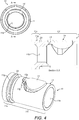
- the housing 11 has an upper end 11u and a lower end 111, see figs 3 and 4 .
- the housing 11 is sealed to the bore of the valve body 5v at seal 18, disposed in a circumferential groove 11g at the upper end 11u of the housing 11, below a counterbored upper face of the housing 11.
- Seal 18 is optionally a resilient annular seal in the form of an o-ring, and is compressed between the outer surface of the upper end 11u of the housing 11 and the inner surface of the valve body 5v.
- the lower end of the housing 11l has a reduced outer diameter, and houses the flapper 14. Disposed between the lower end 11l and the upper end 11u of the housing 11 is an annular groove 23, the function of which will be described below.
- the fluid pressure differential acts on the flapper 14 to apply a downward force tending to open the flapper 14.
- the force of the spring 12 is greater than the force of the pressure differential the valve stays in the closed configuration of figure 1 .
- the downward force of the pressure differential overcomes the upward force of the spring 12
- the cartridge 10 as whole is urged axially downwards in the bore 5b against the force of the spring 12.
- the flapper 14 partially opens during this movement by pivoting around the pivot axis 13 as it is no longer retained in position by the activation ring 20 pressing on the upper side of the neck of the flapper 14.
- the housing 11 and the flapper 14 together form the cartridge 10 that is received within the valve body 5v, and retained by the activation ring 20.
- a single cartridge 10 is deployed in the valve assembly 1.
- two cartridges 10 are loaded into the bore 5b in series (more could be loaded in other examples), with their bores 11b in axial alignment.
- the counterbored upper end 11u of the housing 11 of the lower cartridge 10 with its larger outer diameter receives the smaller diameter lower end 11l of the housing 11 of the upper cartridge 1.
- the counterbored upper end 11u of the housing 11 of the upper cartridge 10 receives the lower end of the central body 5c, which has an identical narrow diameter portion adapted to fit into the counterbore of the upper cartridge 10.
- the cartridges 10 can be modular, interchangeable, and identical to one another, and can be axially stacked in the bore 5b in different combinations, for example, 3, 4 or more cartridges 10 can be stacked in this way.
- Each cartridge 10 is optionally retained in the body by a respective activation ring 20.
- the activation ring 20 extends around a the reduced outer diameter of the lower end 11l of the housing 11, between the annular groove 23 and the pivot axis 13 for the flapper 14.
- the pivot axis 13 is axially spaced from the annular groove 23, and the outer diameter of the lower end 111 between them is smooth and cylindrical, so the activation ring optionally 20 slides axially for a limited distance on the outer surface of the lower end 111 of the housing 11, as the housing 11 moves axially within the bore 5b.
- the valve body 5v can be made up by connecting the upper end of the lower body 5l onto the lower end of the valve body 5v by means of screw threads, and offering the spring 12 to the bore of the valve body 5v.
- the valve cartridges 10 are offered to the bore 5b of the valve body 5v, with each activation ring 20 is aligned with the annular groove 23, and radially compressed into the groove 23 as it enters the bore 5b, where it remains during passage of the cartridge 10 through the bore 5b until the activation ring reaches the axial groove 5g on the inner surface of the valve body 5v, at which point the activation ring 20 radially expands into the groove 5g, escaping the annular groove 23 on the outer surface of the housing 11, and permitting relative movement of the housing 11 in the bore 5b with respect to the radially expanded activation ring 20.
- the cartridges 10 can be removable from the valve body 5v. Removal of the cartridge is achieved by exerting high force on the uphole side of the assembly 1 to axially move the housing 11 in the downhole direction. The force applied to the assembly 1 during removal is in excess of the forces that the valve assembly 1 would be subjected to in normal operation, and causes the valve assembly to travel further in the downhole direction than the normal axial displacement of the valve during operation. During this process, the radially extending shoulder formed by the lower face of the upper end 11u engages the upper face of the activation ring 20 and pushes the activation ring 20 so that the activation ring 20 is axially aligned with the annular groove 23 in the housing.
- the housing 11 and activation ring 20 together move axially downwards within the bore 5b, which causes the activation ring to travel axially downwards along the groove 5g in the inner wall of the body 5v.
- the groove 5g At the lower end of the groove 5g, there is a narrowing chamfer which compresses the activation ring 20 radially inwards against its natural outward resilience and forces the activation ring 20 radially into the annular groove 23 on the outer surface of the housing 11. This releases the restriction that the activation ring 20 places on uphole axial movement of the assembly 1 and permits continued movement of the cartridge or cartridges from the valve body 5v, optionally through the lower end of the valve body 5v once the lower body 5l has been removed.
- the valve assembly 1 in this example is actuated by an actuator assembly for use in the oil, gas or water well, where the actuator assembly 50 is optionally incorporated into the NRV tool.
- One example of the actuator assembly 50 is shown in figures 5-10 .
- the actuator assembly 50 is disposed in the actuator body 5a, between the central body 5c and the upper body 5u.
- the actuator assembly 50 comprises a shuttle device, here in the form of a shuttle sleeve 80 having a bore that is co-axial with the axis of the actuator body 5a.
- the shuttle sleeve 80 optionally comprises a one piece sleeve having an upper portion 80u, a lower portion 80l, and a central portion 80c having a detent mechanism in the form of a collet device.
- the sleeve 80 is urged into a natural position by a biasing mechanism 81, which in this example takes the form upper and lower springs 81u, 81l, arranged radially around the upper and lower portions 80u, 80l of the sleeve 80.
- the springs 81 are optionally coiled springs arranged co-axial with the actuator body 5a and the shuttle sleeve 80.
- the springs 81 are optionally preloaded and held in compression between the tool body 5 and respective upper and lower spring sleeves 82u and 82l, and are biased in opposite directions, and optionally with balanced forces.
- the spring sleeves 82 urge the shuttle sleeve 80 within the actuator body 5a into the figure 5 natural or resting configuration.
- the spring rates and preloads of the upper and lower springs 81 can be different, to provide different force thresholds during running in and latching, or overpull during removal of components from the actuator assembly.
- the upper spring 81u is maintained in compression between the lower end of the upper body 5u, and an upper end of the spring sleeve 82u, and urges the upper spring sleeve 82u downwards in the bore 5b.
- the upper spring 81u optionally surrounds the upper end 80u of the sleeve 80.
- the lower spring 81l optionally surrounds the lower end 80l of the sleeve 80, and is maintained in compression between the upper end of the central body 5c, and a lower end of the spring sleeve 82l, and urges the lower spring sleeve 821 upwards in the bore 5b.
- the springs 81u, 81l act in axially opposite directions, urging the sleeve 80 into the natural position shown in figure 5 in the absence of any other forces.
- the springs 81 are radially surrounded by the actuator body 5a, the bore of which forms a portion of the throughbore of the tool body 5.
- the spring sleeves 82 each have a stepped structure with an inner flange forming a shoulder 82s arranged to engage a shoulder 83s of the shuttle sleeve 80.
- the central portion 80c of the shuttle sleeve 80 comprises a detent mechanism which controls the movement of the shuttle sleeve 80 and the operation of the actuator assembly as will be described below.
- the detent mechanism takes the form of a collet device having at least one collet member 83.
- a plurality of collet members 83 are circumferentially spaced around the central portion 80c of the shuttle sleeve 80.
- Each collet member 83 comprises a collet finger 83f attached in a cantilever manner to the shuttle sleeve 80 at one end of the collet finger 83f, and a collet head 83h on the free end of the collar finger 83f.
- Each collet head 83h optionally has a radially expanded cross-section, as best shown in figure 5 .
- the shape of each collet head 83h is relatively complex, and each collet head 83h is multifaceted.
- Each collet head 83h has inner and outer parallel flat faces, which in this example extend parallel to the axis of the bore through the tool body 5.
- each collet head 83h also has radially extending upper and lower end faces, which optionally extend perpendicular to the axis-parallel inner and outer faces of the head 83h, and which are also flat. Further, the axially extending outer face is connected to each radially extending end face by an inclined face.
- the axially extending inner face is connected to each radially extending end face by an inclined face.
- the inclined faces connecting the end face with the inner and outer faces at the upper end of the head 83h optionally diverge in different directions. Therefore, at the upper end of the head 83h, the radially extending end face is connected to the outer face by an inclined face that extends radially outward at an angle less than 90 degrees, as best shown in figure 5 . Conversely, at the upper end of the head 83h, the radially extending end face is connected to the inner face by an inclined face that extends radially inward at a similar angle.
- the inclined face connecting the outer face with the radially extending end face is inclined radially inwards, whereas the inclined face connecting the inner face with the radially extending end face is inclined radially outwards.
- the net result of this arrangement is that the head 83h is multifaceted and polygonal, having a number of faces arranged at different angles, optionally in a regular and optionally symmetrical arrangement.
- the inclined faces at the upper end diverge away from one another, and those at the lower end converge towards one another.
- the angles of the inner and outer inclined faces are equal and opposite, and are less than 90 degrees.
- the angles of the inclined faces are optionally the same.
- the spring sleeves 82u, 82l have opposing ends that are counterbored to receive the head 83h of the collet device 83.
- a chamfered shoulder is provided connecting the narrower diameter of the counter bore to a larger diameter of the spring sleeve 82.
- the chamfered shoulder is arranged at the same angle as the inclined faces of the head 83h.
- each spring sleeve 82u, 82l is a close fit with the inner diameter of the bore of the actuator body 5a.
- Each spring sleeve 82u, 82l is biased axially within the bore towards the other, and engages and opposite face of an internal ridge 65 extending radially inwards from the inner surface of the actuator body 5a.
- each spring 81u, 81l is maintained in compression within the actuator body 5a between the respective upper and central body portions 5u, 5c, acting to drive the spring sleeves 82u, 82l in opposite directions against opposing faces of the internal ridge 65.
- the spring sleeves 82 each have a stepped structure with a radially inwardly extending flange providing a shoulder 82s arranged to engage the shuttle sleeve 80 and drive it axially within the bore towards the ridge 65.
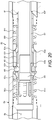
- the shoulders 82s of the upper and lower spring sleeves 82u, 82l engage radially outwardly extending shoulders 83s on the shuttle sleeve 80, which are advantageously arranged between the radially inwardly extending flanges on the spring sleeves and the ridge 65, so that axial movement of either of the spring sleeves 82 towards the ridge 65 engages the shoulders between the spring sleeves and the shuttle sleeve, and drives the shuttle sleeve 80 towards the figure 5 natural position until the axially facing end faces of the spring sleeves 82 abut the opposite faces of the ridge 65, as shown in Fig 20 .
- axial movement of the shuttle sleeve 80 relative to either one of the spring sleeves 82u, 82l causes the shoulders to enter engage, and causes the shuttle sleeve 80 to drive axial movement of the relevant spring sleeve 82, which compresses the spring and allows continued axial movement until a portion of the shuttle sleeve 80 engages a radially inwardly extending restriction the inner diameter of on one of the upper body portion 5u or central body portion 5c.
- the spring sleeves 82 thus move with the collet and as this happens, the collet head 83 expands into the internal diameter of the main actuator body 5a which is exposed as the spring sleeves 82 move axially away from the ridge 65.
- the flanges of the spring sleeves 82 permit the transmission of force from the shuttle sleeve 80 to the spring sleeves to force them in opposite axial directions away from the ridge 65 to compress the springs 81 as the shuttle sleeve 80 moves axially in the bore, as will be described below.
- the natural resting position of the shuttle sleeve 80 is arranged such that the distal end of the collet finger 82f, i.e. the head 83, is positioned radially inside the internal ridge 65 on the actuator body 5a.
- the internal ridge 65 protrudes into the bore of the actuator body 5a to create a small narrowed portion of the bore 5b.
- the two axially-spaced springs 81u, 81l are pressed against the internal ridge 65 with no axial force being applied to the shuttle sleeve as long as the shuttle sleeve 80 remains in the natural resting position shown in figure 5 .
- An actuator member in this example in the form of an actuating sleeve 61 having a bore with an axis parallel to the axis of the bore 5b, is deployed through the bore of the tool body 5 from the surface, for example, via wireline, and passes through the bore of the shuttle sleeve 80 as shown in figure 6 , such that the shuttle sleeve 80 radially surrounds at least a portion of the actuating sleeve 61.
- the actuating sleeve 61 is co-axial with the shuttle sleeve 80 and the actuator body 5a.
- the actuating sleeve 61 has an annular groove 63 formed in its outer diameter, and close to its upper end, and a chamfered shoulder 62f below it facing the lower end of the actuating sleeve 61.
- the annular groove 63 has chamfered upper and lower ends, optionally set at the same angle as the inclined faces on the head 83h of the collet device.
- the wall thickness and the outer diameter of the actuating sleeve 61 both reduce, so that the section of the actuating sleeve 61 below the chamfered shoulder 62f has a reduced diameter, and a reduced wall thickness.
- the downwardly facing chamfered shoulder 62f on the outer diameter of the actuating sleeve 61 engages with an upwardly facing inclined face on the inner surface of the collet head 83h, as shown in figure 6 .
- the downwardly facing chamfered shoulder 62f and the upwardly facing inclined face on the inner surface of the collet head 83h are set at the same angle.
- the smaller outer diameter of the actuating sleeve 61 below the chamfered shoulder 62f can pass through the collet device without engaging the collets, but the larger outer diameter of the actuating sleeve is wider than the inner faces of the collet head 83h, so further axial travel of the actuating sleeve 61 past this point pushes the collet heads 83h (and therefore the whole of the shuttle sleeve 80) downwardly in the bore 5a of the actuator body 5a.
- Figure 7 shows the position after the actuating sleeve 61 has moved further downhole through the shuttle sleeve 80, under force applied from further uphole, optionally from the surface.
- the collet head 83h cannot move radially outward around the cantilever connection with the sleeve at the opposite end of the collet finger, until the head 83h has moved axially downwards for a sufficient distance to disengage from the ridge 65.
- the chamfered shoulder 62f of the actuating sleeve 61 is initially still engaged with the collet finger head 83, and the downward movement of the actuating sleeve 61 continues to urge the shuttle sleeve 80 axially in the direction of travel of the actuating sleeve 61, energising the lower springs 81.
- the range of axial movement of the shuttle sleeve 80 is limited by the lower end of the shuttle sleeve 80 bottoming out on an inner shoulder on the central body portion 5c as shown in figure 7 . At this stage, the shuttle sleeve 80 cannot move any further in the axial direction, and the spring 81 does not compress any further.
- the head 83h of the collet device has now moved down sufficiently to be clear of the internal ridge 65, and is no longer restricted against radial movement, so the head 83h moves radially outward into the space between the internal ridge 65 and the upper end of the spring sleeve 82l, which allows the inner face of the head 83h to move radially away from the chamfered shoulder 62f by pivotal movement around the cantilever connection with the shuttle sleeve 80.
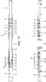
- the actuating sleeve 61 can then resume its downward movement within the bore until the chamfered shoulder 62f engages the upper surface of an inwardly extending and upwardly facing chamfered shoulder 5f on the inner surface of the central body portion 5c, at which point further axial movement of the actuating sleeve 61 is prevented. This is the position shown in figures 15-17 , and figure 8 .
- the actuating sleeve 61 is thus prevented from moving any further downhole and in this example is in position to actuate the downhole tool.
- the head 83h cannot move past through the narrow annular space between the inner surface of the ridge 65 and the outer surface of the large diameter portion of the actuating sleeve 61 between the recess 63 and the shoulder 62f, so until the actuating sleeve 61 has reached the end of its downward travel, the shuttle sleeve 80 is held in the position shown in figure 7 , but with the collet head 83h radially extended and engaging the lower surface of the ridge 65, and with the lower spring sleeve 82l compressing the lower spring 81l.
- the annular groove 63 in the outer diameter of the actuating sleeve 61 is axially aligned with the radially extended collet head 83h, and positioned radially inside it.
- the head 83h is therefore no longer kept in the radially extended position by the large diameter inner surface of the actuating sleeve 61, and is allowed to move resiliently in a radial inward direction into the annular groove 63 in the outer diameter of the actuating sleeve 61.
- Figure 9 shows the start of the retraction process for recovering the actuating sleeve 61 from the wellbore when the valve is to be closed.
- the actuating sleeve 61 includes an internal fishing neck 66 for retraction of the sleeve by e.g. a wireline or other fishing tool which can hook onto the inner surface of the sleeve 61.
- the collet finger head 83 engages a chamfered shoulder 63s in the lower end of the annular recess 63 as shown in figure 9 .
- the shuttle sleeve 80 is thus moved axially in the uphole direction of travel of the actuating sleeve 61, energising the springs 81, as shown in figure 10 .
- the collet head 83h moves above the internal ridge 65 and is free to expand in a radial direction away from the axis of the bore of the shuttle sleeve 80, as the head 83h moves up the inclined face of the lower chamfered surface 63s, and once more moves along the larger diameter portion of the outer surface of the actuating sleeve 61 below the recess 63.
- the collet head 83h remains in its radially expanded configuration above the ridge 65 until the chamfered surface 62f moves axially past the collet head 83h and permits its resilient return to its resting configuration, parallel to the axis.
- the collet head 83h is still maintained above the ridge 65, despite being urged by the action of the upper spring 81u in a downward axial direction as it cannot fit into the narrow annular space between the larger diameter of the actuator sleeve 61 and the ridge 65.
- the collet head 83h can move radially inwards, allowing the shuttle sleeve 80 to resume the natural position shown in figure 11 under the force of the upper spring 81u, as the remainder of the actuating sleeve 61 below the chamfered surface 62f is withdrawn from the tool.
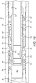
- FIGS 11-17 show the valve assembly 1 together with the actuator assembly 50.
- the valve assembly 1 can be actuated into the open configuration either under the force of fluid pressure alone, or by mechanical actuation, in this example by using the axial movement of the actuating sleeve 61.
- the actuating sleeve 61 actuates the valve assemblies by passing through the shuttle sleeve 80 as described above. For brevity, this process is not described again here.
- FIG. 19 shows a close up view of the valve assembly 1 with the actuating sleeve 61 in its operative position.
- the actuating sleeve 61 is sufficiently long that some axial movement (which can be restricted to the length of the recess 63 in which the collet finger head 83 sits) during operation is permissible while still maintaining the flappers 14 in their open configuration.
- the collet head 83h will engage the in the recess 63 and prevent any further axial movement uphole under normal operating conditions.
- Retraction of the actuating sleeve 61 optionally returns the flappers 14 to their closed positions, as the resilient force of the spring 12 pushes the valve housings 11 axially in the uphole direction, leading to the flappers 14 abutting the activation ring 20 and pivoting around to close.
- Figure 23 shows a modification of the arrangement shown in Figure 15 , in which the same reference numbers are used.
- the actuating sleeve 61' is longer than the actuation sleeve 61, and extends all the way through the flappers 14 and into the lower body 5l when the head 83h is engaged in the groove 63.
- This isolates the spring 12 in a cavity helps to keep the flappers 14 in an open configuration, and helps to avoid snagging or damaging the flappers when tools are run into the hole.
- the figure 23 arrangement includes a travel stop sleeve 5t surrounding the spring 12, which has a smaller diameter than the spring sleeve 12s, and limits its downward travel in the bore.
- valve assembly can be used in coring operations.
- valve member is curved in order to optimise (e.g. minimise) radial wall thickness while retaining a throughbore of sufficient size to run and pull wireline retrievable core barrels through the tool.
- an actuator member is used to actuate the valve into an open configuration.
- the curved valve member maximises the throughbore inner diameter and thereby minimises flow velocities and associated body and seal erosion through the valve.
- valve is intended primarily for use as a coring downhole non-return valve, where the valve prevents backflow and also retains a pressure differential, for example in managed pressure drilling or underbalanced drilling situations, where wireline retrievable core barrels must be removed from the well when statically underbalanced drilling fluid is being used.
- the shuttle device can also be used as part of a coring operation.
- an actuator member is run on wireline retrievable core barrel. This configuration of the apparatus utilises the core barrel running tool to transport the actuator member to the valve assembly, where passage of the actuator member through the valve assembly actuates the valve or valves into the open configuration.
- the actuator member Once the actuator member has passed sufficiently through the valve assembly in order to actuate the valve or valves to the open configuration, it is optionally locked into position, with axial movement prevented by the shuttle device.
- the actuator member is held in said position while the core barrel running tool and wireline pass through to either collect or deposit a new core barrel.
- the actuator member When the running tool passes back through the actuator member during retraction of the tool from the wellbore, the actuator member is optionally collected as part of the retraction process. Removal of the actuator member from the valve assembly permits the valve assembly to return to its standard operating configuration.
- valve assembly return of the valve assembly to its normal operating configuration allows pressure to be bled off above the valve for retrieval of the core barrel at surface.
- valve assembly is optimised to give a low differential pressure rating but maximising the diameter of the throughbore to allow a wireline conveyed core barrel to pass through the flapper valves.
- This can optionally allow a large enough bore diameter to allow wireline core barrels to be run or retrieved through the valve, which allows non return valves to be used as downhole safety valves during wireline coring operations and in managed pressure or underbalanced drilling operations. This represents an advancement in safety and environmental containment as it can help to prevent backflow of well fluids up the drillstring in such operations.
- the flapper valve assembly can be run in the drillstring as part of the bottom hole assembly above the main coring assembly.
- the actuating sleeve 61 can be mounted on a running/retrieval tool immediately above the core barrel retrieval assembly.
- the core barrel retrieval assembly reaches the flappers it forces them open mechanically (or optionally they can be opened by circulation down the drillpipe) and passes through them.
- the lock open or actuating sleeve 61 reaches its installed position with the head 83h in the groove 63, the sleeve 61 is released from its running tool on the wireline and locks into position holding the flappers in the open position as shown in Figure 23 .
- the wireline core retrieval assembly then optionally continues to run into the hole to retrieve the core barrel with the actuating sleeve 61 in place across the flappers 14 protecting the wire from being trapped or severed by the flappers 14, and protecting the flappers 14 from damage by the tool string.
- the running / retrieval tool on the wireline assembly passes back through the actuating sleeve 61 and unlatches the actuating sleeve 61 from the valve assembly on the way back up.
- the sleeve 61 is unlatched from the valve assembly it optionally locks back onto the running / retrieval tool.
- the remainder of the core barrel retrieval tool and core barrel is pulled through the flappers.
- the flappers 14 are held open either mechanically by the core barrel retrieval tool or optionally by circulation down the drillpipe. Once the core barrel is retrieved through the flappers 14 circulation can be stopped and the flappers 14 will close preventing backflow in the drillpipe.
- a larger core barrel can be used below the lock open/actuating sleeve 61 (of greater diameter then the lock open sleeve 61 itself) and the wireline itself is protected from being caught or severed by the flappers 14 unintentionally closing upon it as it passes through the valve.
- the diameter of core barrel is then only limited by the inner bore diameter of the flapper housing 11.
- FIG. 24-27 a second example of part of an NRV tool 100 in accordance with the invention is shown and comprises a valve assembly 101 and optionally an actuator assembly 150 essentially as described in the corresponding features above in relation to the first example, and therefore these are not described in detail in the second example, but the reader is referred to the above descriptions for details of these features.
- valve assembly 101 and actuator assembly 150 are to be used in a drill string.
- the NRV tool 100 is formed from a number of tubulars in the form of five body sections, these being a top sub 105u, a body section 105a in which the actuator assembly 150 is housed, a central or mid sub 105c, a body section 105v in which the valve assembly 101 is housed, and a bottom sub 105l.
- the valve assembly 101 may be connected to a central or mid sub 105c when other components, for example the actuator assembly 150, are to be used during valve operations, or optionally the valve assembly 101 may alternatively be directly connected to a top sub in which case, the second example of the NRV tool 100 does not incorporate the actuator assembly 150.
- Figure 24 shows the valve assembly 101 in a closed configuration, with flappers 114 positioned such that fluid flow through the bore 105b is restricted. Apertures A provide a means of washing the uppermost end (left hand end as shown in Figure 24 ) of the valve cartridges 110 to remove any debris that may prevent axial movement of the cartridges 110.
- First spacer 190 is positioned between the uphole end of the valve assembly 101 and the downhole end of the mid sub 105c, such that the valve assembly 101 is axially spaced apart from the mid sub 105c by the thickness of the first spacer 190 which may be the required one inch (25.4mm) thick.
- the valves 114 remain in the closed configuration once the connection between the mid sub 105c and the valve assembly 101 is torqued up.
- valve assembly 101 During operational use, it may be that pressure builds up below the valves 114 and becomes trapped beneath them. This pressure must be bled off before, e.g., another drill stand may be added into the string below the bottom sub 105l of the valve assembly 101.
- valves 114 are kept in their closed configuration and conventional pressure bleed-off apparatus is placed above the string.
- wireline pressure control equipment is placed above the uppermost end of the drill string (not shown), for example a stuffing box through which wireline passes, sealed so that pressure integrity in the drill string is not lost.
- a lock-open sleeve (described above as lock open/actuator sleeve 61) is connected to the end of the wireline and run into the drill string via the stuffing box and into the bore of the actuator assembly 150 during connection of the pressure control equipment to the string.
- the parts of the string above the still-closed valves 114 may be pressured up to balance the pressure differential between the string below the valves 114 and above the valves 114.
- the lock-open sleeve is then run further through the actuator assembly 150 and into the valve assembly 101 to open the valves 114 and release the trapped pressure into a bleed-off line, which may be connected to the drill string above the NRV tool 100 via a T-piece, or may be connected into the wireline pressure control equipment.
- the valve assembly 101 of Figures 24 to 27 is threadably connected to but axially spaced from a mid sub 105c by at least one first spacer 190 that is positioned between the pin connector of the mid sub 105c and the box connector of the valve assembly 101, so that when the connection is made up, the first spacer 190 separates the mid sub 105c from the valve assembly 101 by approximately 1 inch (25.4mm), although the spacing distance can change according to operational configurations and the relative sizes of the connectors, for example.
- the first spacer 190 provides a surface for the mid sub 105c to be torqued against to tighten the connection between the mid sub 105c and the valve assembly 101.
- the first spacer 190 is in the form of two half-shells, and the two half-shells are placed in position between the mid sub 105c and the valve assembly 101 to form a full annular ring 190.
- the first spacer 190 is tapered in cross-section, with its thickest cross-sectional point at its inner diameter; i.e., the spacer 190 reduces in thickness in a radial direction outwards from the spacer's 190 inner diameter. This resists radial movement of the spacer 190 relative to the sub 105c and the valve assembly 101, as the spacer 190 is effectively dovetailed into the connection and retained in position by the thicker inner portion.
- the spacer 190 has one flat (in use, uppermost) planar face that contacts the shoulder surface of the mid sub 105c at the end of the pin connector.
- the spacer 190 has an opposing face that is angled to form the tapered cross-section, where the angled face contacts the correspondingly angled end of the box connector on the valve assembly 101. Having at least one planar face allows the connection to be fully torqued as the mid sub 105c fully contacts the surface of the planar face of the spacer 190.
- the spacer 190 has a first maximum thickness, for example one inch (25.4mm), wherein the axial dimension of each spacer is measured at an outer radius.
- valve assembly 101 can be directly connected to a bottom sub 1051 at its downhole end and a top sub (e.g. 105u; direct connection not shown) at its uphole end, i.e. the valve assembly 101 may be used independently of the actuator assembly 150, and the valve assembly 101 may then be placed into the drill string.
- a top sub e.g. 105u; direct connection not shown
- connection between the mid sub 105c and the valve assembly 101 is broken at a location above the valve assembly 101.
- the connection is broken by backing the connection out by one turn (optionally the connection between the top sub 105u and the valve assembly 101, where the valve assembly 101 is being used independently of the actuator assembly 150), which loosens the connection enough to remove the spacer 190.
- the connection is tightened, for example by making up the connection by five turns, which brings the edges of the sub into contact with the edges of the valve assembly 101.
- the additional axial space freed up by removal of the spacer 190 allows the pin connector of the sub to axially travel further into the box connector of the valve assembly 101.
- valve assembly 101 In situations where the actuator assembly 150 is omitted and the top sub 105u is connected directly to the valve assembly 101, as the pin connector of the top sub 105u travels axially into the box connector of the valve assembly 101 it engages the uppermost valve cartridge 110 adjacent to the box connector. As the pin connector of the top sub 105u continues to be threaded into the box it pushes the adjacent (uppermost) valve cartridge 110 in the same axial, downhole, direction. The axial movement of the valve cartridge 110 pivots the valve 114 around the pivot axis (described above as pivot axis 13) into an open configuration.
- the example of the valve assembly 101 shown in Figures 24-27 has two valve cartridges 110 connected in series.
- both the mid sub 105c or the top sub 105u can be used in conjunction with the spacers 190, 191, 192 to open the valves 114 in this way.
- the actuator assembly 150 is in place the mid sub 105c is used.
- the top sub 105u can replace the mid sub 105c and can be used to change the configuration of the valves 114 in a similar manner to the mid sub 105c.
- valves 114 are open prior to commencing bleed-off, mud is pumped through the valve assembly 101 to test the valve configuration. After the bleed-off procedure is completed, the valves 114 can be returned to the closed configuration, where flow of fluid is resisted by the valves 114 obturating the bore 105b. To return the valves 114 to the closed configuration, the connection is backed out by as many turns as were required to tighten the connection after the spacer 190 was removed, for example, five turns.
- spacer 190 may be replaced into the connection and the connection re-torqued against the surface of the spacer 190. This spaces the pin and box connections of the sub and the valve assembly 101 so that the valve cartridges 110 are not engaged by the pin connection, and the valves 114 may return to the closed configuration.
- a spacer 191 with a lesser maximal thickness than spacer 190 may be installed in the connection and the connection re-torqued.
- the reduced thickness of spacer 191 allows the pin connection to compress the spring 112 that biases the valve cartridges 110 in the uphole direction, thereby disengaging the spring 112 so that it no longer acts on the valve cartridges 110.
- the valves 114 then remain in the open configuration, falling in the downhole direction under the influence of gravity.
- the spacer 191 thus both permits torqueing up of the connection and prevents the spring 112 from acting on the valve assembly 101 to return the valves 114 to the closed configuration.
- a one-inch (25.4mm) thick (or other appropriate dimension) spacer 192 can be placed between the top sub 105u and the actuator assembly 150.
- the actuator assembly 150 is threadably connected to mid sub 105c, which is in turn connected to the valve assembly 101.
- a spacer 190 ( Figure 26 ), or a thinner spacer 191 ( Figure 27 ), can be placed between the mid sub 105c and the valve assembly 101 as described above.
- Having the spacer 192 placed between the top sub 105u and the actuator assembly 150 means that the top sub 105u can be run straight into the valve assembly 101 if the actuator assembly 150 is removed.
- valve assembly 101 can be used with or without the actuator assembly 150.
- the actuator assembly 150 With the actuator assembly 150 in place there are 5 body sections: top sub 105u, actuator assembly housing 105a, mid sub 105c, valve assembly housing 105v and bottom sub 105l.
- the actuator assembly 150 is used there are only 3 main body sections, top sub 105u, valve assembly housing 105v and bottom sub 105l.
- the mid sub 105c and actuator assembly housing 105a are removed, the top sub 105u pin threads into the box connector that the mid sub 105c pin formerly fitted, and has an identical profile. In this way opening of the valves 114 can be achieved by the same method with either the mid sub 105c pin or the top sub 105u pin.
- all 5 body sections are required for the lock open sleeve method of opening the valve, however, all 5 body sections are required.
- the spacer 192 between the top sub 105u and the actuator assembly housing 105a acts to space out the axial length of the pin 105up on the top sub 105u from the actuator assembly housing 105a, and to permit torqueing up of the top sub 105u, as the mating faces of the top sub 105u and actuator assembly housing 105a are not parallel; instead the upper end face of the actuator assembly 105a has a dovetail profile and the lower end face of the top sub 105u has a flat (perpendicular to the long axis of the NRV tool 100) profile.
- the actuator assembly 150 is optional, the top sub 105u may be interchanged with the mid sub 105c when the actuator assembly 150 (and therefore the actuator assembly housing 105a) is not required. This means that the overall axial length of the top sub pin 105up and its spacer 192 must be identical to the overall axial length of the mid sub pin 105cp and it's corresponding spacer 190.
Landscapes
- Engineering & Computer Science (AREA)
- Life Sciences & Earth Sciences (AREA)
- Geology (AREA)
- Mining & Mineral Resources (AREA)
- Physics & Mathematics (AREA)
- Environmental & Geological Engineering (AREA)
- Fluid Mechanics (AREA)
- General Life Sciences & Earth Sciences (AREA)
- Geochemistry & Mineralogy (AREA)
- Mechanical Engineering (AREA)
- Lift Valve (AREA)
Claims (14)
- Un ensemble clapet (1) pour commander un écoulement de fluide dans un alésage traversant d'une conduite de puits de forage d'un puits de pétrole, de gaz ou d'eau, l'ensemble comprenant :un corps (5v) ayant un axe et étant en communication fluidique avec la conduite de puits de forage,et au moins un clapet comprenant un organe de clapet (14) disposé dans un logement de clapet (11) dans le corps (5v), le logement de clapet (11) étant conçu pour se mouvoir de façon axiale à l'intérieur du corps (5v),et incluant un mécanisme de déplacement (12) conçu pour solliciter le logement de clapet (11) de façon axiale à l'intérieur du corps (5v),dans lequel l'organe de clapet (14) est conçu pour être actionné entre une configuration ouverte et une configuration fermée par mouvement axial du logement de clapet (11) à l'intérieur du corps (5v),dans lequel le clapet est conçu pour être ouvert par un différentiel de pression, résultant d'un écoulement de fluide dans l'alésage traversant dans un sens allant du haut de trou vers le fond de trou, agissant de part et d'autre du clapet,dans lequel le mécanisme de déplacement (12) est configuré pour solliciter l'organe de clapet (14) jusqu'à la configuration fermée ;dans lequel l'ensemble clapet (1) inclut un organe de commande de clapet (20) conçu pour commander le mouvement axial du logement de clapet (11) dans le corps (5v) ;caractérisé par le fait que l'ensemble clapet (1) incorpore un décalage radial entre un point de contact entre l'organe de clapet (14) et l'organe de commande de clapet (20), et un axe de pivotement (13) de l'organe de clapet (14), grâce à quoi des portions se mettant en prise réciproquement de l'organe de commande de clapet (20) et de l'organe de clapet (14) sont espacées de façon radiale de l'axe de pivotement (13) de l'organe de clapet (14), de sorte que quand l'organe de clapet (14) se meut de la configuration ouverte à la configuration fermée, l'organe de clapet (14) vient buter contre l'organe de commande de clapet (20) afin de solliciter l'organe de clapet (14) en rotation autour de l'axe de pivotement (13) à mesure que le logement (11) coulisse de façon axiale relativement à l'organe de commande de clapet (20).
- Un ensemble clapet tel que revendiqué dans la revendication 1, dans lequel le clapet comprend un clapet antiretour et l'organe de clapet comprend un battant (14).
- Un ensemble clapet tel que revendiqué dans la revendication 1 ou la revendication 2, dans lequel l'organe de clapet (14) a au moins une et facultativement deux faces non planes formées en un arc s'étendant au moins partiellement autour d'un axe d'un
- Un ensemble clapet tel que revendiqué dans l'une quelconque des revendications 1 à 3, dans lequel le logement (11) et l'organe de clapet (14) forment une cartouche (10) qui est reçue à l'intérieur d'un alésage (5b) du corps (5v), et laquelle peut être retirée de l'alésage (5b) du corps (5v).
- Un ensemble clapet tel que revendiqué dans l'une quelconque des revendications 1 à 4, dans lequel l'organe de clapet (14) est couplé de façon pivotante au logement (11) par un arbre de pivotement (13p) formé en tant que partie solidaire d'un élément parmi le logement de clapet (11) et l'organe de clapet (14) ; dans lequel l'arbre de pivotement solidaire (13p) comprend une paire de saillies cylindriques s'étendant à partir de surfaces opposées d'un élément parmi le logement de clapet (11) et l'organe de clapet (14) et au moins une portion de l'arbre (13p) est reçue à l'intérieur d'un évidement sous la forme d'au moins une rainure (13g) formé dans l'autre élément parmi le logement de clapet (11) et l'organe de clapet (14).
- Un ensemble clapet tel que revendiqué dans l'une quelconque des revendications 1 à 5, l'ensemble clapet (1) comprenant au moins un joint d'étanchéité (17) collé sur un élément parmi l'organe de clapet (14) et le logement de clapet (11), agencé pour assurer l'étanchéité entre le logement de clapet (11) et l'organe de clapet (14) ; le joint d'étanchéité (17) étant un joint d'étanchéité élastique conçu pour assurer l'étanchéité en compression entre le logement de clapet (11) et l'organe de clapet (14) ; et le joint d'étanchéité (17) étant protégé de la voie d'écoulement de fluide.
- Un ensemble clapet tel que revendiqué dans l'une quelconque des revendications 1 à 6, l'ensemble (1) comprenant un resserrement radial s'étendant de façon radiale dans l'alésage (11b) du logement de clapet (11) de sorte que l'ensemble clapet (1) comprend au moins deux aires de section transversale agissant ensemble comme une buse qui crée un différentiel de pression durant l'écoulement de fluide à travers le logement de clapet (11) de sorte qu'il existe une pression plus élevée d'un côté de l'organe de clapet (14) relativement à l'autre côté de l'organe de clapet (14).
- Un ensemble clapet tel que revendiqué dans la revendication 7, dans lequel une aire de section transversale est rendue étanche par un joint d'étanchéité annulaire (18), et une autre aire de section transversale est formée par un siège de clapet sur lequel l'organe de clapet (14) est conçu pour s'assoir quand l'ensemble clapet (1) est dans la configuration fermée.
- Un ensemble clapet tel que revendiqué dans la revendication 8, dans lequel le différentiel de pression de part et d'autre du clapet actionne l'organe de clapet (14) entre les configurations ouverte et fermée.
- Un ensemble clapet tel que revendiqué dans l'une quelconque des revendications 1 à 9, dans lequel l'organe de commande de clapet (20) se met en prise de façon sélective avec l'organe de clapet (14) et commande son mouvement relativement au logement de clapet (11) ; dans lequel l'organe de commande de clapet (20) est fixé du point de vue de la rotation relativement à l'organe de clapet (14) ; et dans lequel la portée de mouvement axial de l'organe de commande de clapet (20) à l'intérieur du corps (5v) est limitée par un épaulement sur le corps (5v) de clapet.
- Un ensemble clapet tel que revendiqué dans l'une quelconque des revendications 1 à 10, dans lequel l'organe de clapet (14) comprend une queue décalée ayant un épaulement (14s) à faces plates comprenant une première face plate et une deuxième face plate (14e), les première et deuxième faces plates (14e) étant raccordées par un coin arrondi sur l'organe de clapet (14) ; dans lequel dans la configuration fermée, une première face plate sur l'organe de commande de clapet (20) se met en prise avec la première face plate sur la queue décalée de l'organe de clapet (14), et dans lequel le mécanisme de déplacement (12) comprend un ressort élastique (12) qui pousse la première face plate sur la queue décalée de l'organe de clapet (14) contre la première face plate de l'organe de commande de clapet (20) ; et dans lequel dans la configuration ouverte, une deuxième face plate sur l'organe de commande de clapet (20) se met en prise avec la deuxième face plate (14e) sur la queue décalée de l'organe de clapet (14).
- Un ensemble clapet tel que revendiqué dans l'une quelconque des revendications 1 à 11, dans lequel le mouvement axial du logement (11) à l'intérieur du corps (5v) pour faire changer l'ensemble clapet (1) entre des configurations fermée et ouverte est entraîné par un différentiel de pression de fluide de part et d'autre du clapet ; dans lequel le mouvement axial du logement (11) est conçu pour exciter le mécanisme de déplacement (12).
- Un ensemble clapet tel que revendiqué dans l'une quelconque des revendications 1 à 12, comprenant en outre un ensemble actionneur (50) conçu pour changer l'état d'actionnement de l'ensemble clapet (1), l'ensemble actionneur (50) comprenant un corps (5a), un organe d'actionneur (61) conçu pour changer de configurations dans le corps (5a) afin de changer un état d'actionnement de l'ensemble clapet (1), et un dispositif navette (80) conçu pour retenir l'organe d'actionneur (61) dans différentes configurations dans le corps (5a) ; dans lequel le dispositif navette (80) est conçu pour changer de configurations à l'intérieur du corps (5a) relativement à l'organe d'actionneur (61), et a un mécanisme d'arrêt (80c) conçu pour se mettre en prise avec l'organe d'actionneur (61) dans une première configuration du dispositif navette (80) et de l'organe d'actionneur (61) afin de restreindre le mouvement de l'organe d'actionneur (61) à l'intérieur du corps (5a), et dans lequel dans une deuxième configuration du dispositif navette (80) et de l'organe d'actionneur (61), le mécanisme d'arrêt (80c) permet le mouvement de l'organe d'actionneur (61) à l'intérieur du corps (5a) afin d'actionner l'ensemble clapet (1), et dans lequel le dispositif navette (80) a un mécanisme de retour (81) conçu pour solliciter le dispositif navette (80) jusqu'à la première configuration.
- Un procédé de commande d'un écoulement de fluide dans un alésage traversant d'une conduite de puits de forage d'un puits de pétrole, de gaz ou d'eau, le procédé incluant le fait de faire s'écouler du fluide à travers un clapet disposé dans un corps (5v) étant en communication fluidique avec la conduite de puits de forage, le clapet comprenant au moins un organe de clapet (14) disposé dans un logement de clapet (11), dans lequel le logement (11) peut se mouvoir de façon axiale par rapport au corps (5v), et dans lequel un mécanisme de déplacement (12) est configuré pour solliciter le logement de clapet (11) afin qu'il se meuve dans une direction axiale par rapport au corps (5v), dans lequel le mouvement axial du logement (11) par rapport au corps (5v) actionne l'organe de clapet (14) entre une configuration ouverte et une configuration fermée, et dans lequel le clapet est conçu pour être ouvert par un différentiel de pression, résultant d'un écoulement de fluide dans l'alésage traversant dans un sens allant du haut de trou vers le fond de trou, agissant de part et d'autre du clapet, dans lequel le mécanisme de déplacement (12) est configuré pour solliciter l'organe de clapet (14) jusqu'à la configuration fermée ;
dans lequel l'ensemble clapet (1) inclut un organe de commande de clapet (20) conçu pour commander le mouvement axial du logement de clapet (11) dans le corps (5v) ; caractérisé par le fait que l'ensemble clapet (1) incorpore un décalage radial entre un point de contact entre l'organe de clapet (14) et l'organe de commande de clapet (20), et un axe de pivotement (13) de l'organe de clapet (14), grâce à quoi des portions se mettant en prise réciproquement de l'organe de commande de clapet (20) et de l'organe de clapet (14) sont espacées de façon radiale de l'axe de pivotement (13) de l'organe de clapet (14), de sorte que quand l'organe de clapet (14) se meut de la configuration ouverte à la configuration fermée, l'organe de clapet (14) vient buter contre l'organe de commande de clapet (20) afin de solliciter l'organe de clapet (14) en rotation autour de l'axe de pivotement (13) à mesure que le logement (11) coulisse de façon axiale relativement à l'organe de commande de clapet (20).
Applications Claiming Priority (2)
| Application Number | Priority Date | Filing Date | Title |
|---|---|---|---|
| GB1521341.6A GB2545002B (en) | 2015-12-03 | 2015-12-03 | A valve assembly |
| PCT/GB2016/053787 WO2017093745A1 (fr) | 2015-12-03 | 2016-12-01 | Ensemble vanne |
Publications (2)
| Publication Number | Publication Date |
|---|---|
| EP3384126A1 EP3384126A1 (fr) | 2018-10-10 |
| EP3384126B1 true EP3384126B1 (fr) | 2021-04-21 |
Family
ID=55234349
Family Applications (1)
| Application Number | Title | Priority Date | Filing Date |
|---|---|---|---|
| EP16816333.5A Active EP3384126B1 (fr) | 2015-12-03 | 2016-12-01 | Ensemble vanne |
Country Status (4)
| Country | Link |
|---|---|
| US (1) | US11519233B2 (fr) |
| EP (1) | EP3384126B1 (fr) |
| GB (1) | GB2545002B (fr) |
| WO (1) | WO2017093745A1 (fr) |
Families Citing this family (15)
| Publication number | Priority date | Publication date | Assignee | Title |
|---|---|---|---|---|
| CN109505993B (zh) * | 2018-11-08 | 2023-07-07 | 深圳大学 | 可增加密封比压的岩心筒密封结构 |
| US11371297B1 (en) | 2019-02-09 | 2022-06-28 | Terry Cree | Wireline depth monitoring system with valve lockout |
| DE102019211004A1 (de) * | 2019-07-25 | 2021-01-28 | Festo Se & Co. Kg | Ventil |
| CN111485854A (zh) * | 2020-04-27 | 2020-08-04 | 四川大学 | 一种矿山用内防喷保瓦斯接头 |
| US11215031B2 (en) | 2020-06-02 | 2022-01-04 | Baker Hughes Oilfield Operations Llc | Locking backpressure valve with shiftable valve sleeve |
| US11359460B2 (en) | 2020-06-02 | 2022-06-14 | Baker Hughes Oilfield Operations Llc | Locking backpressure valve |
| US11215028B2 (en) | 2020-06-02 | 2022-01-04 | Baker Hughes Oilfield Operations Llc | Locking backpressure valve |
| US11215030B2 (en) * | 2020-06-02 | 2022-01-04 | Baker Hughes Oilfield Operations Llc | Locking backpressure valve with shiftable valve seat |
| US11365605B2 (en) | 2020-06-02 | 2022-06-21 | Baker Hughes Oilfield Operations Llc | Locking backpressure valve |
| US11215026B2 (en) * | 2020-06-02 | 2022-01-04 | Baker Hughes Oilfield Operations Llc | Locking backpressure valve |
| US11230906B2 (en) * | 2020-06-02 | 2022-01-25 | Baker Hughes Oilfield Operations Llc | Locking backpressure valve |
| GB2600709A (en) * | 2020-11-04 | 2022-05-11 | Welleng Science & Tech Ltd | Valve apparatus |
| CN114352215B (zh) * | 2022-01-11 | 2024-10-01 | 中国海洋石油集团有限公司 | 分支井完井管柱双管卡盘 |
| US12404744B2 (en) * | 2023-03-08 | 2025-09-02 | Halliburton Energy Services, Inc. | Wireline retrievable opening prong |
| US12110748B1 (en) * | 2023-04-04 | 2024-10-08 | Drilling Tools International, Inc. | Turbulence reducing downhole apparatus |
Family Cites Families (33)
| Publication number | Priority date | Publication date | Assignee | Title |
|---|---|---|---|---|
| US3016914A (en) * | 1958-11-14 | 1962-01-16 | Baker Oil Tools Inc | Drill pipe float valves |
| US4248264A (en) * | 1979-12-31 | 1981-02-03 | Hydril Company | Internal mud saver valve |
| US4531587A (en) * | 1984-02-22 | 1985-07-30 | Baker Oil Tools, Inc. | Downhole flapper valve |
| US5564675A (en) * | 1994-10-19 | 1996-10-15 | Camco International Inc. | Subsurface safety valve of minimized length |
| WO1998026156A1 (fr) * | 1996-12-09 | 1998-06-18 | Baker Hughes Incorporated | Commande electrique de vanne de securite |
| US20040031534A1 (en) * | 2001-12-05 | 2004-02-19 | Sun Isle Casual Furniture, Llc | Floor covering from synthetic twisted yarns |
| US7063156B2 (en) | 2002-04-16 | 2006-06-20 | Schlumberger Technology Corporation | Tubing fill and testing valve |
| US7021386B2 (en) * | 2003-08-18 | 2006-04-04 | Halliburton Energy Services, Inc. | Safety valve having extension spring closure mechanism |
| US7299880B2 (en) * | 2004-07-16 | 2007-11-27 | Weatherford/Lamb, Inc. | Surge reduction bypass valve |
| US7252153B2 (en) * | 2005-02-01 | 2007-08-07 | Halliburton Energy Services, Inc. | Bi-directional fluid loss device and method |
| GB0509800D0 (en) * | 2005-05-13 | 2005-06-22 | Petrowell Ltd | Apparatus |
| US7434625B2 (en) * | 2005-06-01 | 2008-10-14 | Tiw Corporation | Downhole flapper circulation tool |
| AU2006318890A1 (en) * | 2005-11-24 | 2007-05-31 | Churchill Drilling Tools Limited | Downhole tool |
| US7537062B2 (en) * | 2006-08-14 | 2009-05-26 | Sunstone Corporation | Flapper valve and actuator |
| GB0716049D0 (en) * | 2007-08-17 | 2007-09-26 | Welltools Ltd | Switchable circulating tool |
| US7703532B2 (en) * | 2007-09-17 | 2010-04-27 | Baker Hughes Incorporated | Tubing retrievable injection valve |
| US7971652B2 (en) * | 2008-10-31 | 2011-07-05 | Chevron U.S.A. Inc. | Linear actuation system in the form of a ring |
| US8424842B2 (en) * | 2009-04-15 | 2013-04-23 | Baker Hughes Incorporated | Rotationally-actuated flapper valve and method |
| WO2011005826A1 (fr) * | 2009-07-09 | 2011-01-13 | James Reaux | Aménagement de vanne de sécurité de fond à commande en surface, avec vanne principale et vanne auxiliaire |
| US20110088908A1 (en) * | 2009-10-15 | 2011-04-21 | Baker Hughes Incorporated | Flapper valve |
| GB201003996D0 (en) * | 2010-03-11 | 2010-04-21 | Enovate Systems Ltd | Well barrier |
| GB2489267B (en) * | 2011-03-23 | 2015-06-10 | David Bell Conner | Wellbore valve assembly |
| US8967269B2 (en) * | 2011-07-20 | 2015-03-03 | Baker Hughes Incorporated | Tubular valving system and method |
| GB201205954D0 (en) * | 2012-04-03 | 2012-05-16 | Cff Technologies Ltd | Downhole actuator |
| US9133688B2 (en) * | 2012-08-03 | 2015-09-15 | Tejas Research & Engineering, Llc | Integral multiple stage safety valves |
| US9217311B2 (en) * | 2012-11-05 | 2015-12-22 | Baker Hughes Incorporated | Flapper valve and method of valving a tubular |
| US8978775B2 (en) * | 2012-11-28 | 2015-03-17 | Halliburton Energy Services, Inc. | Downhole valve assembly and methods of using the same |
| WO2015020634A1 (fr) * | 2013-08-06 | 2015-02-12 | Halliburton Energy Services, Inc. | Mécanisme de fermeture d'obturateur à rondelle ondulée |
| US9534476B2 (en) * | 2013-11-26 | 2017-01-03 | Baker Hughes Incorporated | Scale-inhibiting coating |
| GB2524522B (en) * | 2014-03-25 | 2020-03-25 | Nat Oilwell Varco Lp | Coupling assembly and protective ring therefor |
| US10190397B2 (en) * | 2014-05-13 | 2019-01-29 | Weatherford Technology Holdings, Llc | Closure device for a surge pressure reduction tool |
| GB2532970A (en) * | 2014-12-03 | 2016-06-08 | Nat Oilwell Varco Uk Ltd | A Connection and Protective Ring Therefor |
| US20160341002A1 (en) * | 2015-05-22 | 2016-11-24 | Baker Hughes Incorporated | Plug-actuated sub |
-
2015
- 2015-12-03 GB GB1521341.6A patent/GB2545002B/en active Active
-
2016
- 2016-12-01 WO PCT/GB2016/053787 patent/WO2017093745A1/fr not_active Ceased
- 2016-12-01 US US15/778,515 patent/US11519233B2/en active Active
- 2016-12-01 EP EP16816333.5A patent/EP3384126B1/fr active Active
Non-Patent Citations (1)
| Title |
|---|
| None * |
Also Published As
| Publication number | Publication date |
|---|---|
| EP3384126A1 (fr) | 2018-10-10 |
| GB2545002A (en) | 2017-06-07 |
| GB2545002B (en) | 2017-12-20 |
| US11519233B2 (en) | 2022-12-06 |
| US20180347301A1 (en) | 2018-12-06 |
| GB201521341D0 (en) | 2016-01-20 |
| WO2017093745A1 (fr) | 2017-06-08 |
Similar Documents
| Publication | Publication Date | Title |
|---|---|---|
| EP3384126B1 (fr) | Ensemble vanne | |
| US10738570B2 (en) | Tubular isolation valve resettable lock open mechanism | |
| EP2003286B1 (fr) | Bouchon hydraulique extractible actionné par tubage enroulé | |
| US9267338B1 (en) | In-well disconnect tool | |
| US7712538B2 (en) | Method and apparatus for multi-positioning a sleeve | |
| US7040406B2 (en) | Subsea riser disconnect and method | |
| EP1676975A2 (fr) | Equipement sous-marin de déconnexion de colonne montante et procédé | |
| DK2699761T3 (en) | Ball valve safety plug | |
| NO317023B1 (no) | Bronnverktoy med et dobbelt aktueringssystem | |
| EP3452688B1 (fr) | Isolation d'anneau dans des opérations de forage/broyage | |
| WO2017118858A1 (fr) | Outil de désaccouplement de fond de trou, outil de fond de trou et procédé | |
| WO2015080727A1 (fr) | Dispositif de commande rotatif avec verrou sollicité en engagement | |
| GB2594120A (en) | Riser adapter quick connection assembly | |
| US20170130561A1 (en) | Drilling Flow Control Tool | |
| CN111601948A (zh) | 具有球致动的可扩张密封和/或压力增强的可径向扩张花键的夹头 | |
| US7347269B2 (en) | Flow tube exercising tool | |
| US20060278406A1 (en) | Rod lock for ram blowout preventers | |
| US5862865A (en) | Insert gas lift system | |
| US9422790B2 (en) | Safety valve with lockout capability and methods of use | |
| CN111615581A (zh) | 用于地下多级阀门致动的轮廓选择性套管 | |
| EP2971477B1 (fr) | Siège de bille pouvant être repositionné pour des outils actionnés hydrauliquement | |
| US20060260796A1 (en) | One trip flow tube exercising tool | |
| GB2465052A (en) | Method and device for securing a well | |
| WO1992012923A1 (fr) | Appareil servant a soulever du materiel lourd | |
| AU2005332690A1 (en) | Rod lock for ram blowout preventers |
Legal Events
| Date | Code | Title | Description |
|---|---|---|---|
| STAA | Information on the status of an ep patent application or granted ep patent |
Free format text: STATUS: UNKNOWN |
|
| STAA | Information on the status of an ep patent application or granted ep patent |
Free format text: STATUS: THE INTERNATIONAL PUBLICATION HAS BEEN MADE |
|
| PUAI | Public reference made under article 153(3) epc to a published international application that has entered the european phase |
Free format text: ORIGINAL CODE: 0009012 |
|
| STAA | Information on the status of an ep patent application or granted ep patent |
Free format text: STATUS: REQUEST FOR EXAMINATION WAS MADE |
|
| 17P | Request for examination filed |
Effective date: 20180517 |
|
| AK | Designated contracting states |
Kind code of ref document: A1 Designated state(s): AL AT BE BG CH CY CZ DE DK EE ES FI FR GB GR HR HU IE IS IT LI LT LU LV MC MK MT NL NO PL PT RO RS SE SI SK SM TR |
|
| AX | Request for extension of the european patent |
Extension state: BA ME |
|
| DAV | Request for validation of the european patent (deleted) | ||
| DAX | Request for extension of the european patent (deleted) | ||
| STAA | Information on the status of an ep patent application or granted ep patent |
Free format text: STATUS: EXAMINATION IS IN PROGRESS |
|
| 17Q | First examination report despatched |
Effective date: 20200226 |
|
| GRAP | Despatch of communication of intention to grant a patent |
Free format text: ORIGINAL CODE: EPIDOSNIGR1 |
|
| STAA | Information on the status of an ep patent application or granted ep patent |
Free format text: STATUS: GRANT OF PATENT IS INTENDED |
|
| INTG | Intention to grant announced |
Effective date: 20201125 |
|
| GRAS | Grant fee paid |
Free format text: ORIGINAL CODE: EPIDOSNIGR3 |
|
| GRAA | (expected) grant |
Free format text: ORIGINAL CODE: 0009210 |
|
| STAA | Information on the status of an ep patent application or granted ep patent |
Free format text: STATUS: THE PATENT HAS BEEN GRANTED |
|
| AK | Designated contracting states |
Kind code of ref document: B1 Designated state(s): AL AT BE BG CH CY CZ DE DK EE ES FI FR GR HR HU IE IS IT LI LT LU LV MC MK MT NL NO PL PT RO RS SE SI SK SM TR |
|
| RBV | Designated contracting states (corrected) |
Designated state(s): AL AT BE BG CH CY CZ DE DK EE ES FI FR GR HR HU IE IS IT LI LT LU LV MC MK MT NL NO PL PT RO RS SE SI SK SM TR |
|
| REG | Reference to a national code |
Ref country code: CH Ref legal event code: EP |
|
| REG | Reference to a national code |
Ref country code: DE Ref legal event code: R096 Ref document number: 602016056593 Country of ref document: DE Ref country code: IE Ref legal event code: FG4D |
|
| REG | Reference to a national code |
Ref country code: AT Ref legal event code: REF Ref document number: 1384808 Country of ref document: AT Kind code of ref document: T Effective date: 20210515 |
|
| REG | Reference to a national code |
Ref country code: NL Ref legal event code: FP |
|
| REG | Reference to a national code |
Ref country code: LT Ref legal event code: MG9D |
|
| REG | Reference to a national code |
Ref country code: AT Ref legal event code: MK05 Ref document number: 1384808 Country of ref document: AT Kind code of ref document: T Effective date: 20210421 |
|
| REG | Reference to a national code |
Ref country code: NO Ref legal event code: T2 Effective date: 20210421 |
|
| PG25 | Lapsed in a contracting state [announced via postgrant information from national office to epo] |
Ref country code: HR Free format text: LAPSE BECAUSE OF FAILURE TO SUBMIT A TRANSLATION OF THE DESCRIPTION OR TO PAY THE FEE WITHIN THE PRESCRIBED TIME-LIMIT Effective date: 20210421 Ref country code: BG Free format text: LAPSE BECAUSE OF FAILURE TO SUBMIT A TRANSLATION OF THE DESCRIPTION OR TO PAY THE FEE WITHIN THE PRESCRIBED TIME-LIMIT Effective date: 20210721 Ref country code: AT Free format text: LAPSE BECAUSE OF FAILURE TO SUBMIT A TRANSLATION OF THE DESCRIPTION OR TO PAY THE FEE WITHIN THE PRESCRIBED TIME-LIMIT Effective date: 20210421 Ref country code: LT Free format text: LAPSE BECAUSE OF FAILURE TO SUBMIT A TRANSLATION OF THE DESCRIPTION OR TO PAY THE FEE WITHIN THE PRESCRIBED TIME-LIMIT Effective date: 20210421 Ref country code: FI Free format text: LAPSE BECAUSE OF FAILURE TO SUBMIT A TRANSLATION OF THE DESCRIPTION OR TO PAY THE FEE WITHIN THE PRESCRIBED TIME-LIMIT Effective date: 20210421 |
|
| PG25 | Lapsed in a contracting state [announced via postgrant information from national office to epo] |
Ref country code: IS Free format text: LAPSE BECAUSE OF FAILURE TO SUBMIT A TRANSLATION OF THE DESCRIPTION OR TO PAY THE FEE WITHIN THE PRESCRIBED TIME-LIMIT Effective date: 20210821 Ref country code: LV Free format text: LAPSE BECAUSE OF FAILURE TO SUBMIT A TRANSLATION OF THE DESCRIPTION OR TO PAY THE FEE WITHIN THE PRESCRIBED TIME-LIMIT Effective date: 20210421 Ref country code: GR Free format text: LAPSE BECAUSE OF FAILURE TO SUBMIT A TRANSLATION OF THE DESCRIPTION OR TO PAY THE FEE WITHIN THE PRESCRIBED TIME-LIMIT Effective date: 20210722 Ref country code: RS Free format text: LAPSE BECAUSE OF FAILURE TO SUBMIT A TRANSLATION OF THE DESCRIPTION OR TO PAY THE FEE WITHIN THE PRESCRIBED TIME-LIMIT Effective date: 20210421 Ref country code: SE Free format text: LAPSE BECAUSE OF FAILURE TO SUBMIT A TRANSLATION OF THE DESCRIPTION OR TO PAY THE FEE WITHIN THE PRESCRIBED TIME-LIMIT Effective date: 20210421 Ref country code: PT Free format text: LAPSE BECAUSE OF FAILURE TO SUBMIT A TRANSLATION OF THE DESCRIPTION OR TO PAY THE FEE WITHIN THE PRESCRIBED TIME-LIMIT Effective date: 20210823 Ref country code: PL Free format text: LAPSE BECAUSE OF FAILURE TO SUBMIT A TRANSLATION OF THE DESCRIPTION OR TO PAY THE FEE WITHIN THE PRESCRIBED TIME-LIMIT Effective date: 20210421 |
|
| REG | Reference to a national code |
Ref country code: DE Ref legal event code: R097 Ref document number: 602016056593 Country of ref document: DE |
|
| PG25 | Lapsed in a contracting state [announced via postgrant information from national office to epo] |
Ref country code: EE Free format text: LAPSE BECAUSE OF FAILURE TO SUBMIT A TRANSLATION OF THE DESCRIPTION OR TO PAY THE FEE WITHIN THE PRESCRIBED TIME-LIMIT Effective date: 20210421 Ref country code: CZ Free format text: LAPSE BECAUSE OF FAILURE TO SUBMIT A TRANSLATION OF THE DESCRIPTION OR TO PAY THE FEE WITHIN THE PRESCRIBED TIME-LIMIT Effective date: 20210421 Ref country code: DK Free format text: LAPSE BECAUSE OF FAILURE TO SUBMIT A TRANSLATION OF THE DESCRIPTION OR TO PAY THE FEE WITHIN THE PRESCRIBED TIME-LIMIT Effective date: 20210421 Ref country code: ES Free format text: LAPSE BECAUSE OF FAILURE TO SUBMIT A TRANSLATION OF THE DESCRIPTION OR TO PAY THE FEE WITHIN THE PRESCRIBED TIME-LIMIT Effective date: 20210421 Ref country code: RO Free format text: LAPSE BECAUSE OF FAILURE TO SUBMIT A TRANSLATION OF THE DESCRIPTION OR TO PAY THE FEE WITHIN THE PRESCRIBED TIME-LIMIT Effective date: 20210421 Ref country code: SM Free format text: LAPSE BECAUSE OF FAILURE TO SUBMIT A TRANSLATION OF THE DESCRIPTION OR TO PAY THE FEE WITHIN THE PRESCRIBED TIME-LIMIT Effective date: 20210421 Ref country code: SK Free format text: LAPSE BECAUSE OF FAILURE TO SUBMIT A TRANSLATION OF THE DESCRIPTION OR TO PAY THE FEE WITHIN THE PRESCRIBED TIME-LIMIT Effective date: 20210421 |
|
| PLBE | No opposition filed within time limit |
Free format text: ORIGINAL CODE: 0009261 |
|
| STAA | Information on the status of an ep patent application or granted ep patent |
Free format text: STATUS: NO OPPOSITION FILED WITHIN TIME LIMIT |
|
| 26N | No opposition filed |
Effective date: 20220124 |
|
| PG25 | Lapsed in a contracting state [announced via postgrant information from national office to epo] |
Ref country code: IS Free format text: LAPSE BECAUSE OF FAILURE TO SUBMIT A TRANSLATION OF THE DESCRIPTION OR TO PAY THE FEE WITHIN THE PRESCRIBED TIME-LIMIT Effective date: 20210821 Ref country code: AL Free format text: LAPSE BECAUSE OF FAILURE TO SUBMIT A TRANSLATION OF THE DESCRIPTION OR TO PAY THE FEE WITHIN THE PRESCRIBED TIME-LIMIT Effective date: 20210421 |
|
| PG25 | Lapsed in a contracting state [announced via postgrant information from national office to epo] |
Ref country code: MC Free format text: LAPSE BECAUSE OF FAILURE TO SUBMIT A TRANSLATION OF THE DESCRIPTION OR TO PAY THE FEE WITHIN THE PRESCRIBED TIME-LIMIT Effective date: 20210421 Ref country code: IT Free format text: LAPSE BECAUSE OF FAILURE TO SUBMIT A TRANSLATION OF THE DESCRIPTION OR TO PAY THE FEE WITHIN THE PRESCRIBED TIME-LIMIT Effective date: 20210421 |
|
| REG | Reference to a national code |
Ref country code: CH Ref legal event code: PL |
|
| REG | Reference to a national code |
Ref country code: BE Ref legal event code: MM Effective date: 20211231 |
|
| PG25 | Lapsed in a contracting state [announced via postgrant information from national office to epo] |
Ref country code: LU Free format text: LAPSE BECAUSE OF NON-PAYMENT OF DUE FEES Effective date: 20211201 Ref country code: IE Free format text: LAPSE BECAUSE OF NON-PAYMENT OF DUE FEES Effective date: 20211201 |
|
| PG25 | Lapsed in a contracting state [announced via postgrant information from national office to epo] |
Ref country code: BE Free format text: LAPSE BECAUSE OF NON-PAYMENT OF DUE FEES Effective date: 20211231 |
|
| PG25 | Lapsed in a contracting state [announced via postgrant information from national office to epo] |
Ref country code: LI Free format text: LAPSE BECAUSE OF NON-PAYMENT OF DUE FEES Effective date: 20211231 Ref country code: CH Free format text: LAPSE BECAUSE OF NON-PAYMENT OF DUE FEES Effective date: 20211231 |
|
| PG25 | Lapsed in a contracting state [announced via postgrant information from national office to epo] |
Ref country code: HU Free format text: LAPSE BECAUSE OF FAILURE TO SUBMIT A TRANSLATION OF THE DESCRIPTION OR TO PAY THE FEE WITHIN THE PRESCRIBED TIME-LIMIT; INVALID AB INITIO Effective date: 20161201 |
|
| PG25 | Lapsed in a contracting state [announced via postgrant information from national office to epo] |
Ref country code: CY Free format text: LAPSE BECAUSE OF FAILURE TO SUBMIT A TRANSLATION OF THE DESCRIPTION OR TO PAY THE FEE WITHIN THE PRESCRIBED TIME-LIMIT Effective date: 20210421 |
|
| PG25 | Lapsed in a contracting state [announced via postgrant information from national office to epo] |
Ref country code: MK Free format text: LAPSE BECAUSE OF FAILURE TO SUBMIT A TRANSLATION OF THE DESCRIPTION OR TO PAY THE FEE WITHIN THE PRESCRIBED TIME-LIMIT Effective date: 20210421 |
|
| PG25 | Lapsed in a contracting state [announced via postgrant information from national office to epo] |
Ref country code: TR Free format text: LAPSE BECAUSE OF FAILURE TO SUBMIT A TRANSLATION OF THE DESCRIPTION OR TO PAY THE FEE WITHIN THE PRESCRIBED TIME-LIMIT Effective date: 20210421 |
|
| PG25 | Lapsed in a contracting state [announced via postgrant information from national office to epo] |
Ref country code: MT Free format text: LAPSE BECAUSE OF FAILURE TO SUBMIT A TRANSLATION OF THE DESCRIPTION OR TO PAY THE FEE WITHIN THE PRESCRIBED TIME-LIMIT Effective date: 20210421 |
|
| PGFP | Annual fee paid to national office [announced via postgrant information from national office to epo] |
Ref country code: NL Payment date: 20251229 Year of fee payment: 10 Ref country code: FR Payment date: 20251229 Year of fee payment: 10 |
|
| PGFP | Annual fee paid to national office [announced via postgrant information from national office to epo] |
Ref country code: DE Payment date: 20251230 Year of fee payment: 10 Ref country code: NO Payment date: 20251231 Year of fee payment: 10 |