EP3384154B1 - Windturbine und verfahren zum betrieb einer windturbine zur verringerung von seitlichen schwingungen - Google Patents
Windturbine und verfahren zum betrieb einer windturbine zur verringerung von seitlichen schwingungen Download PDFInfo
- Publication number
- EP3384154B1 EP3384154B1 EP16813347.8A EP16813347A EP3384154B1 EP 3384154 B1 EP3384154 B1 EP 3384154B1 EP 16813347 A EP16813347 A EP 16813347A EP 3384154 B1 EP3384154 B1 EP 3384154B1
- Authority
- EP
- European Patent Office
- Prior art keywords
- wind turbine
- vibration
- frequency
- edgewise
- controller
- Prior art date
- Legal status (The legal status is an assumption and is not a legal conclusion. Google has not performed a legal analysis and makes no representation as to the accuracy of the status listed.)
- Active
Links
Images
Classifications
-
- F—MECHANICAL ENGINEERING; LIGHTING; HEATING; WEAPONS; BLASTING
- F03—MACHINES OR ENGINES FOR LIQUIDS; WIND, SPRING, OR WEIGHT MOTORS; PRODUCING MECHANICAL POWER OR A REACTIVE PROPULSIVE THRUST, NOT OTHERWISE PROVIDED FOR
- F03D—WIND MOTORS
- F03D7/00—Controlling wind motors
- F03D7/02—Controlling wind motors the wind motors having rotation axis substantially parallel to the air flow entering the rotor
- F03D7/04—Automatic control; Regulation
- F03D7/042—Automatic control; Regulation by means of an electrical or electronic controller
-
- F—MECHANICAL ENGINEERING; LIGHTING; HEATING; WEAPONS; BLASTING
- F03—MACHINES OR ENGINES FOR LIQUIDS; WIND, SPRING, OR WEIGHT MOTORS; PRODUCING MECHANICAL POWER OR A REACTIVE PROPULSIVE THRUST, NOT OTHERWISE PROVIDED FOR
- F03D—WIND MOTORS
- F03D7/00—Controlling wind motors
- F03D7/02—Controlling wind motors the wind motors having rotation axis substantially parallel to the air flow entering the rotor
- F03D7/0296—Controlling wind motors the wind motors having rotation axis substantially parallel to the air flow entering the rotor to prevent, counteract or reduce noise emissions
-
- F—MECHANICAL ENGINEERING; LIGHTING; HEATING; WEAPONS; BLASTING
- F03—MACHINES OR ENGINES FOR LIQUIDS; WIND, SPRING, OR WEIGHT MOTORS; PRODUCING MECHANICAL POWER OR A REACTIVE PROPULSIVE THRUST, NOT OTHERWISE PROVIDED FOR
- F03D—WIND MOTORS
- F03D7/00—Controlling wind motors
- F03D7/02—Controlling wind motors the wind motors having rotation axis substantially parallel to the air flow entering the rotor
- F03D7/022—Adjusting aerodynamic properties of the blades
- F03D7/0224—Adjusting blade pitch
-
- F—MECHANICAL ENGINEERING; LIGHTING; HEATING; WEAPONS; BLASTING
- F03—MACHINES OR ENGINES FOR LIQUIDS; WIND, SPRING, OR WEIGHT MOTORS; PRODUCING MECHANICAL POWER OR A REACTIVE PROPULSIVE THRUST, NOT OTHERWISE PROVIDED FOR
- F03D—WIND MOTORS
- F03D13/00—Assembly, mounting or commissioning of wind motors; Arrangements specially adapted for transporting wind motor components
- F03D13/20—Arrangements for mounting or supporting wind motors; Masts or towers for wind motors
-
- F—MECHANICAL ENGINEERING; LIGHTING; HEATING; WEAPONS; BLASTING
- F03—MACHINES OR ENGINES FOR LIQUIDS; WIND, SPRING, OR WEIGHT MOTORS; PRODUCING MECHANICAL POWER OR A REACTIVE PROPULSIVE THRUST, NOT OTHERWISE PROVIDED FOR
- F03D—WIND MOTORS
- F03D17/00—Monitoring or testing of wind motors, e.g. diagnostics
-
- F—MECHANICAL ENGINEERING; LIGHTING; HEATING; WEAPONS; BLASTING
- F03—MACHINES OR ENGINES FOR LIQUIDS; WIND, SPRING, OR WEIGHT MOTORS; PRODUCING MECHANICAL POWER OR A REACTIVE PROPULSIVE THRUST, NOT OTHERWISE PROVIDED FOR
- F03D—WIND MOTORS
- F03D7/00—Controlling wind motors
- F03D7/02—Controlling wind motors the wind motors having rotation axis substantially parallel to the air flow entering the rotor
- F03D7/0204—Controlling wind motors the wind motors having rotation axis substantially parallel to the air flow entering the rotor for orientation in relation to wind direction
-
- F—MECHANICAL ENGINEERING; LIGHTING; HEATING; WEAPONS; BLASTING
- F03—MACHINES OR ENGINES FOR LIQUIDS; WIND, SPRING, OR WEIGHT MOTORS; PRODUCING MECHANICAL POWER OR A REACTIVE PROPULSIVE THRUST, NOT OTHERWISE PROVIDED FOR
- F03D—WIND MOTORS
- F03D7/00—Controlling wind motors
- F03D7/02—Controlling wind motors the wind motors having rotation axis substantially parallel to the air flow entering the rotor
- F03D7/0272—Controlling wind motors the wind motors having rotation axis substantially parallel to the air flow entering the rotor by measures acting on the electrical generator
-
- F—MECHANICAL ENGINEERING; LIGHTING; HEATING; WEAPONS; BLASTING
- F03—MACHINES OR ENGINES FOR LIQUIDS; WIND, SPRING, OR WEIGHT MOTORS; PRODUCING MECHANICAL POWER OR A REACTIVE PROPULSIVE THRUST, NOT OTHERWISE PROVIDED FOR
- F03D—WIND MOTORS
- F03D7/00—Controlling wind motors
- F03D7/02—Controlling wind motors the wind motors having rotation axis substantially parallel to the air flow entering the rotor
- F03D7/028—Controlling wind motors the wind motors having rotation axis substantially parallel to the air flow entering the rotor controlling wind motor output power
- F03D7/0292—Controlling wind motors the wind motors having rotation axis substantially parallel to the air flow entering the rotor controlling wind motor output power to reduce fatigue
-
- F—MECHANICAL ENGINEERING; LIGHTING; HEATING; WEAPONS; BLASTING
- F05—INDEXING SCHEMES RELATING TO ENGINES OR PUMPS IN VARIOUS SUBCLASSES OF CLASSES F01-F04
- F05B—INDEXING SCHEME RELATING TO WIND, SPRING, WEIGHT, INERTIA OR LIKE MOTORS, TO MACHINES OR ENGINES FOR LIQUIDS COVERED BY SUBCLASSES F03B, F03D AND F03G
- F05B2260/00—Function
- F05B2260/96—Preventing, counteracting or reducing vibration or noise
- F05B2260/966—Preventing, counteracting or reducing vibration or noise by correcting static or dynamic imbalance
-
- F—MECHANICAL ENGINEERING; LIGHTING; HEATING; WEAPONS; BLASTING
- F05—INDEXING SCHEMES RELATING TO ENGINES OR PUMPS IN VARIOUS SUBCLASSES OF CLASSES F01-F04
- F05B—INDEXING SCHEME RELATING TO WIND, SPRING, WEIGHT, INERTIA OR LIKE MOTORS, TO MACHINES OR ENGINES FOR LIQUIDS COVERED BY SUBCLASSES F03B, F03D AND F03G
- F05B2270/00—Control
- F05B2270/30—Control parameters, e.g. input parameters
- F05B2270/32—Wind speeds
-
- F—MECHANICAL ENGINEERING; LIGHTING; HEATING; WEAPONS; BLASTING
- F05—INDEXING SCHEMES RELATING TO ENGINES OR PUMPS IN VARIOUS SUBCLASSES OF CLASSES F01-F04
- F05B—INDEXING SCHEME RELATING TO WIND, SPRING, WEIGHT, INERTIA OR LIKE MOTORS, TO MACHINES OR ENGINES FOR LIQUIDS COVERED BY SUBCLASSES F03B, F03D AND F03G
- F05B2270/00—Control
- F05B2270/30—Control parameters, e.g. input parameters
- F05B2270/327—Rotor or generator speeds
-
- F—MECHANICAL ENGINEERING; LIGHTING; HEATING; WEAPONS; BLASTING
- F05—INDEXING SCHEMES RELATING TO ENGINES OR PUMPS IN VARIOUS SUBCLASSES OF CLASSES F01-F04
- F05B—INDEXING SCHEME RELATING TO WIND, SPRING, WEIGHT, INERTIA OR LIKE MOTORS, TO MACHINES OR ENGINES FOR LIQUIDS COVERED BY SUBCLASSES F03B, F03D AND F03G
- F05B2270/00—Control
- F05B2270/30—Control parameters, e.g. input parameters
- F05B2270/328—Blade pitch angle
-
- F—MECHANICAL ENGINEERING; LIGHTING; HEATING; WEAPONS; BLASTING
- F05—INDEXING SCHEMES RELATING TO ENGINES OR PUMPS IN VARIOUS SUBCLASSES OF CLASSES F01-F04
- F05B—INDEXING SCHEME RELATING TO WIND, SPRING, WEIGHT, INERTIA OR LIKE MOTORS, TO MACHINES OR ENGINES FOR LIQUIDS COVERED BY SUBCLASSES F03B, F03D AND F03G
- F05B2270/00—Control
- F05B2270/30—Control parameters, e.g. input parameters
- F05B2270/329—Azimuth or yaw angle
-
- F—MECHANICAL ENGINEERING; LIGHTING; HEATING; WEAPONS; BLASTING
- F05—INDEXING SCHEMES RELATING TO ENGINES OR PUMPS IN VARIOUS SUBCLASSES OF CLASSES F01-F04
- F05B—INDEXING SCHEME RELATING TO WIND, SPRING, WEIGHT, INERTIA OR LIKE MOTORS, TO MACHINES OR ENGINES FOR LIQUIDS COVERED BY SUBCLASSES F03B, F03D AND F03G
- F05B2270/00—Control
- F05B2270/30—Control parameters, e.g. input parameters
- F05B2270/334—Vibration measurements
-
- F—MECHANICAL ENGINEERING; LIGHTING; HEATING; WEAPONS; BLASTING
- F05—INDEXING SCHEMES RELATING TO ENGINES OR PUMPS IN VARIOUS SUBCLASSES OF CLASSES F01-F04
- F05B—INDEXING SCHEME RELATING TO WIND, SPRING, WEIGHT, INERTIA OR LIKE MOTORS, TO MACHINES OR ENGINES FOR LIQUIDS COVERED BY SUBCLASSES F03B, F03D AND F03G
- F05B2270/00—Control
- F05B2270/30—Control parameters, e.g. input parameters
- F05B2270/335—Output power or torque
-
- F—MECHANICAL ENGINEERING; LIGHTING; HEATING; WEAPONS; BLASTING
- F05—INDEXING SCHEMES RELATING TO ENGINES OR PUMPS IN VARIOUS SUBCLASSES OF CLASSES F01-F04
- F05B—INDEXING SCHEME RELATING TO WIND, SPRING, WEIGHT, INERTIA OR LIKE MOTORS, TO MACHINES OR ENGINES FOR LIQUIDS COVERED BY SUBCLASSES F03B, F03D AND F03G
- F05B2270/00—Control
- F05B2270/80—Devices generating input signals, e.g. transducers, sensors, cameras or strain gauges
- F05B2270/807—Accelerometers
-
- Y—GENERAL TAGGING OF NEW TECHNOLOGICAL DEVELOPMENTS; GENERAL TAGGING OF CROSS-SECTIONAL TECHNOLOGIES SPANNING OVER SEVERAL SECTIONS OF THE IPC; TECHNICAL SUBJECTS COVERED BY FORMER USPC CROSS-REFERENCE ART COLLECTIONS [XRACs] AND DIGESTS
- Y02—TECHNOLOGIES OR APPLICATIONS FOR MITIGATION OR ADAPTATION AGAINST CLIMATE CHANGE
- Y02E—REDUCTION OF GREENHOUSE GAS [GHG] EMISSIONS, RELATED TO ENERGY GENERATION, TRANSMISSION OR DISTRIBUTION
- Y02E10/00—Energy generation through renewable energy sources
- Y02E10/70—Wind energy
- Y02E10/72—Wind turbines with rotation axis in wind direction
Definitions
- the present invention relates to a method of controlling a wind turbine for reducing the edgewise vibrations, wherein a vibration signal indicative of the edgewise vibrations is measured in the wind turbine, a vibration level of at least a whirling mode is determined based on this vibration signal, the vibration level is compared to a threshold value, and the operation of the wind turbine is regulated if the vibration level exceeds the threshold value.
- the present invention also relates to a system of controlling a wind turbine for reducing the edgewise vibrations, wherein an accelerometer arranged in the wind turbine is configured to measure a vibration signal indicative of the edgewise vibrations, and a controller is configured to determine a vibration level of at least a whirling mode based on the vibration signal, wherein the controller is further configured to compare the vibration level to a threshold value and to regulate the operation of the wind turbine if the vibration level exceeds the threshold value.
- sensor units such as accelerometers
- wind turbine blades for measuring various conditions, e.g. the vibration level, of the wind turbine blades.
- these sensor units are likely to fail due to fatigue loads, static electricity or lightning strikes.
- the sensor units are also subjected to a hard environment with large temperature changes and are also likely to get hit by loose objects, e.g. clumps of glue, being thrown around inside the wind turbine blade as it rotates.
- Replacing and servicing such sensor units represent a time-consuming and expensive process which increases the downtime of the wind turbine.
- Such sensor units also add steps to the manufacturing process and increase the total installation costs which are multiple with the number of wind turbine blades.
- Patent publication US 2012/0257967 discloses a method and a controller for generating a pitch angle control signal and, in particular, for controlling an edgewise rotor vibration.
- the pitch angle control signal is generated such that it varies in accordance with a rotor blade vibration motion.
- vibration is measured in the nacelle.
- the disclosure requires a rather complicated processing scheme.
- Another prior art example is shown in US2010/301605A1 .
- An object of the invention is to provide a control method that monitors the vibrations caused by at least one of the whirling modes of the wind turbine.
- An object of the invention is to provide a control method that reduces the whirling mode vibration level.
- An object of the invention is to provide a control method that can be implemented in existing wind turbine control systems.
- An object of the invention is to provide a wind turbine control system capable of monitoring the vibrations caused by at least one of the whirling modes of the wind turbine.
- An object of the invention is to provide a wind turbine control system capable of reducing the whirling mode vibration level.
- An object of the invention is to provide a method and a workable system that can detect edgewise vibrations and to provide actions to mitigate such vibrations. It is also an object to provide an alternative, and particularly a simple and/or flexible alternative prior art teachings, to obtain sufficiently good vibrations signals having a frequency spectrum where peaks indicative of one or more frequencies of undesirable modes can be identified using simple workable analytics.
- An object is achieved by method of controlling a wind turbine for reducing edgewise vibrations, the method comprising acts of regulating a wind turbine as a function of a level and frequency of edgewise vibrations, wherein the edgewise vibration level and frequency are determined as a function of one or two vibration signals obtained from the wind turbine.
- vibration signal may provide sufficient information about a vibration mode. If the vibration signal is obtained from the nacelle, only a single vibration signal has shown to be sufficient.
- the method provides greater flexibility in the location of measuring the vibration signal.
- the method further provides greater flexibility in the choice of type of vibration signal.
- the vibration signal may be obtained from a single vibration signal measured in a nacelle of the wind turbine.
- the vibration signal may be two vibration signals measured on the tower of the wind turbine.
- the vibration signal may be a single vibration signal measured on the tower of the wind turbine.
- the vibration signal is obtained from the tower, two vibration signals, preferably placed in a 90-degrees angle, but in principle in any positive angle, about the yaw-axis, provide sufficient information at all yaw-positions of the nacelle.
- a single vibration signal from the tower may be sufficient. In that case there may be temporal periods with poor signals.
- a single vibration signal may be obtained from the tower and provided by the vibration sensor being moved according to the position of the rotor (about the yaw-axis).
- measuring vibration signals only on the tower can be performed with greater flexibility and the tower structure has surprisingly shown to provide sufficiently good signals to identify edgewise vibrations in the frequency spectrum.
- the tower allows for a variety of vibration sensors to be placed in a variety of locations on the tower to provide sufficiently good signals that are easy or easier to interpret in the frequency domain.
- peaks indicative of edgewise motions have shown to be identifiable; even using simple peak detection methods.
- the vibration signal is obtained from the top-part of the tower.
- the top part may be at least the upper half of the tower or the upper quarter of the tower.
- the top part may be within a distance from the nacelle, such distance may be within the length of the nacelle.
- the frequency of the edgewise vibration is determined from the frequency spectrum of the vibration signal by identifying the frequency location of a pair of peaks in the frequency spectrum.
- the frequency of edgewise vibration is determined from the frequency spectrum of the vibration signal by identifying at least one peak in a predetermined frequency band or frequency range.
- the actual frequency of the edgewise vibration may be determined from such a peak, even a single peak, by adding or subtracting a predetermined frequency to the frequency of the peak.
- the frequency band may be known empirically or determined during the design of the wind turbine or provided by the blade manufacturer.
- the change or growth of a peak may also be used to identify the frequency of edgewise vibration.
- the frequency of edgewise vibration is determined by identifying the frequency location of multiple pairs of peaks or at least one peak in multiple predetermined frequency bands in the frequency spectrum.
- the vibration signal is obtained as a measure side-to-side acceleration of the tower and determined by two sensors placed 90-degrees apart on the yaw-axis and directly on the tower in the top part of the tower.
- the vibration signal is obtained as a measure of tower displacement or tower strain.
- Tower displacement is understood as general mechanical vibrations or movements of a point on the tower.
- Movements or dynamics may be detected by a variety of methods and may be performed from or to a fixed point, for example by use of laser light.
- Strain gauges may also be used to measure tower vibrations that can be used for analysis.
- the level of vibration is determined from the height, amplitude or power of one or more identified peaks.
- the method is also insensitive to absolute measures and for particular vibration signals and their origin, the method allows for simple measures of the level of edgewise vibrations by installing the method and then determine a height or amplitude of a peak in the frequency spectrum, or the power spectrum.
- the act of regulating the operation of the wind turbine comprises one or more acts of:
- the act of regulating which may be an act of corrective action, may be performed by one or more of the above actions.
- the act may be performed as a corrective action to dampen or eliminate an edgewise vibration (mode), which will die.
- the act may be temporally or for a period of time before resuming to the otherwise intended setting.
- the pitch angle of the at least one wind turbine blade is pitched if at least one vibration level exceeds the at least one threshold value.
- An object may be achieved by a wind turbine comprising a wind turbine tower, a nacelle arranged on top of the wind turbine tower, a rotatable rotor with at least one wind turbine blade arranged relative to the nacelle, and a wind turbine control system
- the wind turbine control system comprises at least one vibration sensor configured to measure two vibration signals of the tower dynamics and a controller connected to the two vibration sensors, wherein the controller is configured to determine at least one frequency of an edgewise vibration and the level based on the two vibration signals, and wherein the controller is further configured to compare the vibration level of the at least one edgewise vibration of the at least one determined frequency to at least one threshold value and to regulate the operation of the wind turbine if the vibration level exceeds the at least one threshold value.
- the two vibration sensor's unit are arranged on the wind turbine tower in an angle about the yaw-axis.
- the two vibration sensor's unit are arranged on the top part of the tower.
- the at least one vibration sensor is configured to measure the at least one vibration signal along at least a lateral direction perpendicular to a central rotational axis of the rotor.
- the wind turbine control system is connected to at least one component selected from a pitch mechanism configured to pitch the at least one wind turbine into a pitch angle, a yaw mechanism configured to yaw the nacelle into a yaw angle, a generator configured to generate a power output signal, a power convertor configured to generate another power output signal, and a braking system configured to apply a braking force to the rotor, wherein the controller is configured to regulate the operation of the wind turbine by adjusting at least one control parameter of the at least one component so that the edgewise vibrations are reduced.
- a pitch mechanism configured to pitch the at least one wind turbine into a pitch angle
- a yaw mechanism configured to yaw the nacelle into a yaw angle
- a generator configured to generate a power output signal
- a power convertor configured to generate another power output signal
- a braking system configured to apply a braking force to the rotor
- the controller is configured to execute computer implemented instructions that perform one or more acts described.
- An object of the invention is achieved by a method of controlling a wind turbine for reducing edgewise vibrations, the method comprises the steps of:
- edgewise vibrations is defined as vibrations or deflective movements along an edgewise direction defined by the chord of the wind turbine blades, where the chord extends from the trailing edge to the leading edge of the wind turbine blades.
- This provides a control method that is able to monitor and control the whirling mode vibration level of the wind turbine.
- This also provides a control scheme that is able to regulate the operation of the wind turbine in order to reduce the whirling mode vibrations.
- the present control method is suitable for wind turbines having any number of wind turbine blades, such as two or three wind turbine blades.
- the present control method reduces the risk of large operational loads on the wind turbine blades as the edgewise vibrations are reduced to a minimum.
- the present control method can be implemented into existing wind turbine control systems or into the wind turbine control systems of new wind turbines.
- the at least one whirling mode frequency is determined as function of a rotational speed of a rotor of the wind turbine.
- f whirl is the whirling mode frequency
- f edge is the blade edgewise frequency
- f rotor is the rotational frequency of the rotor.
- the rotational speed may be measured using a rotational speed sensor, e.g. an encoder or an inductive sensor, arranged relative to the rotor.
- the wind turbine may be outfitted with a rotational speed sensor which is positioned relative to the rotor, e.g. the rotor shaft, during installation. This enables the whirling mode frequency to be determined directly based on the rotational speed which in turn allows for an accurate calculation of this whirling mode frequency.
- the rotational speed may also be an existing rotational speed sensor located in or on the wind turbine.
- the present wind turbine control system e.g. the controller, is then electrically connected to this existing rotational speed sensor or to an existing controller in order to receive a speed signal indicative of the rotational speed of the rotor.
- the present controller may be electronically connected to the existing controller or implemented into the existing controller. This reduces the installation costs as the controller can be adapted to communicate with any existing wind turbine systems.
- the at least one vibration signal is measured along a lateral direction perpendicular to a central rotational axis of the rotor of the wind turbine.
- the controller may alternatively determine the whirling mode frequency using the vibration signal of one or more vibration sensors.
- the vibration sensor may be positioned relative to a component of the wind turbine so that it is able to directly or indirectly measure the whirling mode vibrations, e.g. the edgewise vibrations, of the wind turbine blades.
- the component may be a wind turbine blade, a rotor shaft, a gearbox unit, a generator unit, a bearing unit, or another suitable component.
- This vibration sensor may also be used to determine the vibration level of the whirling mode.
- the whirling mode vibrations are preferably measured using one or more accelerometers, but other types of vibration sensor may be used. This also allows the installation costs to be reduced as the existing accelerometers located in the wind turbine may be used to determine the whirling mode frequency.
- the vibration sensor e.g. the accelerometer, used to determine the vibration level and/or the whirling mode frequency may be arranged to measure the vibrations in a stationary frame of reference located at or near the top of the wind turbine.
- the frame of reference may be defined by the nacelle, or the upper part of the wind turbine tower.
- the vibrations may be measured in a rotating frame of reference, e.g. defined by the wind turbine blades, the rotor hub, or the rotor shaft, and then transferred to the stationary frame of reference.
- the vibration signal may be measured along at least a lateral direction perpendicular to a central rotational axis of the rotor shaft as the side-to-side vibrations/accelerations of the wind turbine are indicative of the movements caused by the whirling mode.
- a frequency transformation function is applied to the at least one vibration signal, wherein the vibration level is determined based on this frequency transformed signal.
- the measured vibration signal may be transferred into the frequency domain, e.g. from the time domain, using any type of a frequency transformation function.
- the frequency transformation algorithm may be a Fourier transfer algorithm, e.g. a fast-Fourier transformation, a maximum entropy algorithm, or another suitable frequency transformation algorithm.
- the controller may then analyse this frequency transformed signal in order to determine the whirling mode frequency and optionally the vibration level of the whirling mode. This allows the controller to perform a spectral analysis of the measured vibration signal for determining the whirling mode frequency and optionally the vibration level. Other techniques may be used to determine the whirling mode frequency and/or the vibration level.
- a filter function may be applied to the measured vibration signal, wherein this filtered signal is analysed to determine the vibration level of the whirling mode.
- the filter function may be a discrete filter function. This allows the controller to determine the vibration level in the time domain.
- the method further comprises the step of:
- a first whirling mode frequency and a second whirling mode frequency may be determined by the controller in relation to the rotational direction of the rotor in the rotor plane.
- the rotational direction may be a clockwise direction or an anti-clockwise direction.
- the first whirling mode frequency may be indicative of a whirling mode movement that occurs in an opposite direction compared to the rotational direction.
- the second whirling mode frequency may be indicative of a whirling mode movement that occurs in the same direction as the rotational direction.
- the trailing edge and/or the leading edge of the respective wind turbine blade may move in a substantially elliptically pattern during the whirling mode, wherein this elliptically movement has either a progressive or retrograde effect on the forces acting on the stationary frame of reference, e.g. the nacelle.
- the rotational frequency, e.g. the 1P frequency, of the rotor may be used to calculate the frequency range of the whirling mode, i.e. the whirling mode range. This allows the controller to also monitor the whirling mode range during rotation of the rotor, e.g. in normal power production mode or in another operating mode.
- the method further comprises the step of:
- the controller may use the measured rotational speed or the vibration signal, e.g. the frequency transformed signal, to determine one or more whirling modes of the wind turbine.
- the whirling modes may be determined within a predetermined operating range of the wind turbine, e.g. the operating range of the rotational speed of the rotor.
- the controller may determine at least one whirling mode frequency, e.g. the third whirling mode frequency, of a first whirling mode and at least one whirling mode frequency, e.g. the fourth whirling mode frequency, of a second whirling mode.
- the controller may further determine at least one whirling mode frequency of at least a third whirling mode, and so forth.
- the controller may determine a first and a second whirling mode frequency for each of these whirling modes.
- the operating frequency of the rotor may be used to calculate the whirling mode range associated with each of these whirling modes. This allows the controller to monitor any whirling modes occurring in the operating range of the rotor.
- the individual whirling mode may be monitored individually and in parallel.
- the amplitudes of first and second whirling mode frequencies may be used to determine a vibration level for each respective whirling mode.
- the vibration level may then be compared to an averaged threshold value in order to determine if the operation of the wind turbine needs to be regulated or not.
- an individual vibration level may be determined for each of the first and second whirling mode frequencies.
- the individual vibration levels may then be compared to individual threshold values in order to determine if the operation of the wind turbine needs to be regulated or not.
- the controller may regulate the operation of the wind turbine if at least one of the individual vibration levels or the averaged vibration level exceeds their respective threshold value. This allows for a better monitoring of the vibration level of each respective whirling mode and in turn a better regulating of the operation of the wind turbine.
- the first and second whirling mode frequencies may be monitored and compared to their respective threshold values independently or simultaneously.
- One or more of the whirling modes may also be compared to one or more critical frequencies, e.g. the eigenfrequency of a selected component of the wind turbine.
- the critical frequency may be an eigenfrequency of a drive train of the wind turbine, a passing frequency of the wind turbine blades (e.g. a 3P frequency), or another suitable critical frequency.
- the passing frequency may be determined as any multiples of the number of wind turbine blades and the rotational speed.
- the controller may compare the whirling mode frequency, e.g. the first or second whirling mode frequency, to the critical frequencies in order to detect if the two frequencies are coinciding or close to coincide. This may cause an increase in the measured vibration level which in turn may trigger the regulation process described below if the respective threshold value is exceeded.
- These critical frequencies may also be used to determine the threshold value(s) for the vibration level(s) of each whirling mode.
- the step of regulating the operation of the wind turbine comprises at least one of:
- the controller may adjust the value of one or more control parameters used to control the operation of the wind turbine.
- the control parameter may in example be a control value or a control set point for either pitching the wind turbine blades, rotating the rotor, yawing the nacelle, controlling the generator torque of the generator, controlling the power output or the generator or power convertor, or another suitable control parameter.
- the controller may also regulate the operation of the wind turbine by adjusting a control parameter of a braking system of the wind turbine, e.g. transmitting an activation signal, which in turn slows down the rotation of the rotor.
- the above-mentioned corrective actions may be combined in order to provide a better regulating of the operation of the wind turbine.
- the pitch angle of the at least one wind turbine blade is adjusted by no more than 5 degrees relative to a normal pitch angle if the vibration level exceeds the at least one threshold value.
- the controller preferably adjusts the respective set points for pitching the wind turbine blades relative to a normal set point.
- the normal set point may be defined as a set point for achieving a maximal power production or maintaining a nominal power output.
- the normal set point e.g. the pitch angle
- the normal set point may be adjusted by no more than 5 degrees, preferably between 2 and 4 degrees or any values there in between. This pitching action and subsequent change in the rotational speed have a significant damping effect of the whirling mode vibrations.
- the at least one threshold value is determined based on one or more simulations and/or one or more measurements.
- the threshold value e.g. the averaged threshold value or the individual threshold values, may be determined by performing one or more simulations, wherein the simulation results are then analysed and evaluated in order to determine the suitable threshold values.
- the critical frequencies of the components of the wind turbines may also be taken into account when determining the threshold values.
- the respective threshold values may be determined based on previous measurements, e.g. from the wind turbine or from other wind turbines. The simulations and/or previous measurement may also be used to determine the critical frequencies of the wind turbines and/or the whirling frequency.
- the controller may be configured to perform the above-mentioned control process at regular time intervals or when it is deemed necessary, e.g. by continuously monitoring the whirling mode vibration level.
- the controller may also be configured to update the critical frequencies of the wind turbines and/or the whirling frequency based on at least the current measurement, e.g. after each run of the above-mentioned control process.
- a wind turbine comprising a wind turbine tower, a nacelle arranged on top of the wind turbine tower, a rotatable rotor with at least one wind turbine blade arranged relative to the nacelle, and a wind turbine control system
- the wind turbine control system comprises at least one vibration sensor configured to measure at least one vibration signal indicative of edgewise vibrations in the wind turbine and a controller connected to the at least one vibration sensor, wherein the controller is configured to determine a vibration level based on the at least one vibration signal, wherein the controller is further configured to compare the vibration level to at least one threshold value and to regulate the operation of the wind turbine if the vibration level exceeds the at least one threshold value, characterised in that the controller is configured to determine at least one whirling frequency of at least one whirling mode of the wind turbine, wherein the vibration level is determined by using the at least one whirling mode frequency.
- This provides a wind turbine control system capable of regulating the operation of the wind turbine in the event that the whirling mode vibrations exceed an acceptable level.
- the wind turbine control system is also able to monitor and control the vibration level of the whirling modes during rotation of the rotor.
- the wind turbine may have any number of wind turbine blades, such as two or three wind turbine blades. This reduces the risk of large loads on the wind turbine blades as the edgewise vibrations are reduced to a minimum.
- the at least one vibration sensor unit is arranged relative to the top of the wind turbine tower, wherein the at least one vibration sensor is configured to measure the at least one vibration signal along at least a lateral direction perpendicular to a central rotational axis of the rotor.
- One or more vibration sensors are arranged on or in the wind turbine so that they are able to directly or indirectly measure the whirling mode vibrations occurring in the wind turbine blades.
- the vibration sensors may be arranged relative to a stationary frame of reference as described earlier.
- the vibration sensor is configured to measure the sideward vibrations in the lateral direction and, optionally, the forward and backward vibrations in the axial direction (defined by the central rotational axis of the rotor shaft).
- the vibration sensor may be any type of vibration sensor, such as an accelerometer, a displacement sensor, a strain gauge, a speed sensor, or another vibration sensor. This eliminates the need for arranging the sensors inside the wind turbine blades. This also reduces the risk of a sensor failure as the vibration sensor and its appendages are placed in a less dynamic environment.
- the vibration sensor may advantageously be an existing vibration sensor located in the wind turbine which is capable of direct or indirectly measuring the whirling mode vibrations.
- the vibration sensor is an accelerometer.
- the controller may be configured to communicate with this vibration sensor, e.g. via an existing wind turbine control system.
- the controller may be implemented into the existing wind turbine system. This reduces the installation costs and allows the controller to be adapted to any existing wind turbine control systems.
- the controller is configured to monitor a third whirling mode frequency of a first whirling mode and at least a fourth whirling mode frequency of at least a second whirling mode of the at least one whirling mode within an operating range defined by a rotational speed of the rotor.
- the controller may be configured to monitor the vibration level of any whirling modes within the operating range of the wind turbine.
- the operating range may be defined as the operating range of the rotational speed of the rotor, e.g. extending from a minimum rotation speed to a maximum rotation speed. This operating range may correspond to a frequency band in the frequency domain which extends from a minimum frequency value to a maximum frequency value. This frequency band may then be applied to the frequency transformed signal in the controller.
- the controller may be configured to detect any whirling modes located within that frequency band.
- the controller may be configured to further determine the first and second whirling mode frequencies and the whirling mode range for each of the whirling modes as described earlier. This allows the controller to also monitor the whirling mode range during rotation of the rotor and determine when a corrective action is required.
- the controller may be electrically connected to one or more rotational speed sensors arranged relative to the rotor, e.g. on the rotor shaft, or relative to the passing wind turbine blades for receiving a rotational speed signal indicative of the rotational speed of the rotor.
- the rotational speed sensor may be any type of rotational speed sensor, such as an encoder or an inductive sensor.
- the rotational speed sensor may advantageously be an existing rotational speed sensor located inside or outside on the wind turbine.
- the controller may be connected to the rotational speed sensor and/or the vibration sensor via a wired or wireless connection. This further reduces the installation costs.
- the wind turbine control system is connected to at least one component selected from a pitch mechanism configured to pitch the at least one wind turbine into a pitch angle, a yaw mechanism configured to yaw the nacelle into a yaw angle, a generator configured to generate a power output signal, a power converter to generate another power output signal, and a braking system configured to apply a braking force to the rotor, wherein the controller is configured to regulate the operation of the wind turbine by adjusting at least one control parameter of the at least one component so that the edgewise vibrations are reduced.
- the controller may be configured to initiate one or more corrective actions when the vibration level exceeds the respective threshold value.
- the controller may be configured to directly communicate with the respective components of the wind turbine, or via an existing wind turbine control system.
- the controller may be configured to adjust the control value or control set point of one or more control parameters relative to their normal value or set point.
- the normal value or set point may be defined by the control value or control set point for producing a maximum power output or maintaining a nominal power output. This adjusted control parameter may then be transmitted to the respective component which in turn adjusts its operation accordingly.
- the pitch mechanism, the yaw mechanism, the generator, the power convertor and/or the braking system may be used to regulate the operation of the wind turbine so that the edgewise vibrations of the wind turbine blades are reduced to a minimum.
- the controller is configured to adjust the pitch angle of the at least one wind turbine blade so that the at least one wind turbine blade is pitched out of the wind.
- the pitch mechanism is preferably used to dampen the edgewise vibrations as the pitching action has a significant aerodynamic dampening effect on the whirling mode vibrations in the wind turbine blades.
- the pitching action may result in a subsequent change in the rotational speed which in turn also provides a good dampening effect on the edgewise vibrations.
- the controller may be configured to adjust the control parameter for pitching the respective wind turbine blades relative to their normal control parameter as described earlier. This provides a fast and very effective dampening of the edgewise vibrations.
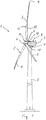
- Fig. 1 shows a wind turbine 1 comprising a wind turbine tower 2 and a nacelle 3 arranged on top of the wind turbine tower 2 using a yaw mechanism 4.
- the yaw mechanism 4 is configured to yaw the nacelle 3 into a yaw angle.
- a rotor comprising at least two wind turbine blades 5 mounted to a rotor hub 6 via a pitch mechanism 7.
- the pitch mechanism 7 is configured to pitch the wind turbine blades 5 into a pitch angle.
- the rotor hub 6 is rotatably connected to a generator 8 arranged in the wind turbine 1 via a rotor shaft.
- Each wind turbine blade 5 comprises a tip end 9 and a blade root 10, wherein the wind turbine blade 5 has an aerodynamic profile defining a leading edge 11 and a trailing edge 12.
- a braking system 13 is arranged relative to the rotor and is configured to apply a braking force to the rotor.
- At least one vibration sensor 14 is arranged on the wind turbine 1 for measuring a vibration signal of the wind turbine 1.
- the vibration sensor 14 forms part of a wind turbine control system wherein a controller is connected to the vibration sensor 14.
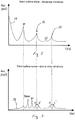
- Fig. 2 shows an exemplary graph of a vibration signal 15 measured in a rotating frame of reference, wherein the vibration signal 15 is measured in the wind turbine blade 5.
- the vibration signal 15 is here shown as an acceleration signal indicative of the edgewise vibrations in the wind turbine blades 5.
- the rotational speed of the rotor may be determined by analysing the vibration signal 15, wherein the peak marked "IP" indicates the rotational frequency of the rotor.
- the vibration signal 15 further includes a plurality of individual edgewise modes indicative of the edgewise vibrations. Here, only a first edgewise mode 16 and a second edgewise mode 17 are shown.
- the vibration signal 15 may be analysed to determine a blade edgewise frequency of the first edgewise mode 16 and a blade edgewise frequency of the second edgewise mode 17.
- the individual edgewise modes 16, 17 are monitored and analysed individually and in parallel.
- Fig. 3 shows an exemplary graph of another vibration signal 18 measured in a stationary frame of reference, wherein the edgewise vibrations in the wind turbine blades 5 are indirectly determined by measuring a vibration signal using a vibration sensor located in the wind turbine tower 2 or the nacelle 3.
- the vibration signal 18 is measured in a lateral direction perpendicular to the rotation axis of the rotor.
- the vibration signal 18 is analysed to determine a first whirling mode frequency, a, and a second whirling mode frequency, b, of each of the edgewise modes 16, 17.
- the first whirling mode frequency is indicative of a backward whirling mode movement that occurs in an opposite direction compared to the rotational direction.
- the second whirling mode frequency is indicative of a forward whirling mode movement that occurs in the same direction compared to the rotational direction.
- the rotational frequency, IP is used to determine a whirling mode range for each whirling mode 16, 17.
- the frequency spectrum of the vibration signal 18 obtained from vibration measurements of the tower 2 or the nacelle 3 shows a first pair of peaks a 1 and b 1 corresponding to a first edgewise vibration mode 16 seen in figure 2 .
- the peak a1 is located at f edge -1P, where 1P is the rotation frequency, and is the "backward whirling mode”.
- the peak b 1 is located at f edge +1P and is the "forward whirling mode".
- the second pair of peaks a 2 and b 2 corresponds to a second edgewise vibration mode 17 seen in figure 2 .
- Identifying one or both of peaks a and b in the frequency spectrum from a vibration simply obtained from vibration measurements in the tower or in the nacelle will allow for determining the corresponding edgewise vibration mode.
- One peak, a or b may also be determined by looking in a band or frequency range in the spectrum.
- the band or frequency may be IP, 2P or in that order.
- a peak identified in such a band may indicate the frequency of a corresponding edgewise mode.
- the vibration signal 18 is transformed into the frequency domain using a frequency transformation function.
- the frequency transformed signal is analysed and at least the vibration levels of the first and second whirling mode frequencies are determined.
- the vibration signal 15, 18 includes a number of critical frequencies, e.g. the eigenfrequencies of the wind turbine tower marked "Tower", of the drivetrain of the wind turbine 1 marked “DT", and of the passing frequency of the wind turbine blades marked "3P".
- the individual critical frequencies may be taken into account when determining the vibration level of the respective edgewise modes 16, 17.
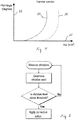
- Fig. 4 shows an exemplary graph of two transfer functions 19, 20 used to determine a corrective action.
- a first transfer function 19 is applied to the vibration level 21 of the first edgewise mode 16 and a second transfer function 20 is applied to the vibration level 21 of the second edgewise mode 17.
- the transfer functions 19, 20 are used to determine a pitch angle offset 22 for adjustment of the pitch angle of the wind turbine blades 5.
- the pitch angle offset 22 is optionally compared to a predetermined threshold value. If the pitch angle offset 22 exceeds this threshold value, then the controller initiates a shutdown procedure and the wind turbine 1 is shut down until the vibration level 21 drops below the respective threshold value.
- the pitch angle offset is used by the pitch mechanism to pitch the wind turbine blades 5 out of the wind relative to a normal pitch angle. The pitching of the wind turbine blades 5 has significant dampening effect of the whirling mode vibrations in the wind turbine blades 5.
- Fig. 5 shows an exemplary flowchart of the control method according to the invention.
- the controller of the wind turbine control system monitors the whirling modes within the operating range of the rotational speed of the rotor.
- the vibration signal 15, 18 is measured using the vibration sensor 14 and transferred to the controller.
- the controller analyses the vibration signal, e.g. in the frequency domain, to determine the first and second whirling mode frequencies of the individual whirling modes 16, 17.
- the controller further determines the individual vibration levels 21 using the whirling mode frequencies.
- the respective vibration levels 21 are then compared to individual threshold values in the controller. If the vibration levels 21 are below the threshold values, then the controller continues to monitor the whirling mode vibrations. If at least one of the vibration levels 21 exceeds its respective threshold value, then the controller determines a suitable corrective action, e.g. a pitch angle offset. Suitable control parameters are then transmitted to the respective component, e.g. the pitch mechanism, which in turn adjusts its operation accordingly.
- a suitable corrective action e.g. a pitch angle offset
Landscapes
- Engineering & Computer Science (AREA)
- Life Sciences & Earth Sciences (AREA)
- Sustainable Development (AREA)
- Sustainable Energy (AREA)
- Chemical & Material Sciences (AREA)
- Combustion & Propulsion (AREA)
- Mechanical Engineering (AREA)
- General Engineering & Computer Science (AREA)
- Physics & Mathematics (AREA)
- Fluid Mechanics (AREA)
- Wind Motors (AREA)
Claims (11)
- Verfahren zum Steuern einer Windturbine zur Verringerung von seitlichen Schwingungen von Laufschaufeln, wobei das Verfahren folgende Handlungen umfasst:
Regulieren einer Windturbine in Abhängigkeit von einem Pegel und einer Frequenz von seitlichen Schwingungen, wobei der Pegel und die Frequenz der seitlichen Schwingungen in Abhängigkeit von einem Schwingungssignal einer Schwingung des Turms der Windturbine von einer Seite zu einer anderen Seite bestimmt werden, das von der Windturbine erhalten wird, wobei die Schwingungen des Turms von der einen Seite zu der anderen Seite aus einem Schwingungssignal erhalten werden, das in der Gondel der Windturbine erhalten wird, und wobei die Frequenz der seitlichen Schwingung aus dem Frequenzspektrum von Schwingungen durch ein Identifizieren des Frequenzstandorts eines Paars von Spitzen in dem Frequenzspektrum bestimmt wird. - Verfahren nach Anspruch 1, wobei die Frequenz der seitlichen Schwingung aus dem Frequenzspektrum des Schwingungssignals durch ein Identifizieren von mindestens einer Spitze in einem vorbestimmten Frequenzband bestimmt wird.
- Verfahren nach Anspruch 2, wobei die Frequenz der seitlichen Schwingung durch ein Identifizieren des Frequenzstandorts von mehreren Paaren von Spitzen oder mindestens einer Spitze in einem vorbestimmten Frequenzband in dem Frequenzspektrum bestimmt wird.
- Verfahren nach Anspruch 2, wobei der Pegel der Schwingung ausgehend von der Höhe oder Leistung von einer oder mehreren identifizierten Spitzen bestimmt wird.
- Verfahren nach Anspruch 1, wobei die Handlung des Regulierens des Betriebs der Windturbine eine oder mehrere der folgenden Handlungen umfasst:Einstellen eines Anstellwinkels der mindestens einen Windturbinenlaufschaufel,Einstellen der Drehgeschwindigkeit des Rotors der Windturbine,Einstellen eines Gierwinkels einer Gondel der Windturbine,Einstellen eines Generatordrehmomentsignals oder eines Leistungsausgabesignals der Windturbine, undAufbringen einer Bremskraft auf die mindestens eine Windturbinenlaufschaufel unter Verwendung eines Bremssystems der Windturbine.
- Verfahren nach Anspruch 5, wobei die eine oder mehreren Handlungen des Einstellens oder Aufbringens als eine Übertragungsfunktion des Schwingungspegels ausgeführt werden.
- Verfahren nach Anspruch 6, wobei der Anstellwinkel der mindestens einen Windturbinenlaufschaufel angestellt wird, falls der mindestens eine Schwingungspegel den mindestens einen Schwellenwert überschreitet.
- Windturbine, die eine Steuerung aufweist, wobei die Steuerung dazu konfiguriert ist, computerimplementierte Anweisungen auszuführen, die das Verfahren nach Anspruch 1 durchführen.
- Windturbine, die einen Windturbinenturm, eine Gondel, die über dem Windturbinenturm angeordnet ist, einen drehbaren Rotor mit mindestens einem Windturbinenlaufrad, der relativ zu der Gondel angeordnet ist und einem Windturbinensteuersystem, wobei das Windturbinensteuersystem einen einzelnen Schwingungssensor, der dazu konfiguriert ist, ein Schwingungssignal entlang mindestens einer Richtung, die senkrecht zu einer zentralen Drehachse des Rotors verläuft, zu messen und eine Steuerung, die dazu konfiguriert ist, das Schwingungssignal zu empfangen, umfasst, wobei die Steuerung dazu konfiguriert ist, mindestens eine Frequenz von seitlichen Schwingungen von Laufschaufeln und den Pegel, der auf dem Frequenzspektrum des Schwingungssignals basiert, durch ein Identifizieren des Frequenzstandorts eines Paars von Spitzen in dem Frequenzspektrum zu bestimmen, und wobei die Steuerung ferner dazu konfiguriert ist, den Schwingungspegel der mindestens einen seitlichen Schwingung der mindestens einen bestimmten Frequenz mit mindestens einem Schwellenwert zu vergleichen und den Betrieb der Windturbine zu regulieren, falls der Schwingungspegel den mindestens einen Schwellenwert überschreitet.
- Windturbine nach Anspruch 9, wobei das Windturbinensteuersystem mit mindestens einer Komponente verbunden ist, die aus einem Anstellmechanismus, der dazu konfiguriert ist, die mindestens eine Windturbine in einen Anstellwinkel anzustellen, einem Giermechanismus, der dazu konfiguriert ist, die Gondel in einen Gierwinkel zu gieren, einem Generator, der dazu konfiguriert ist, ein Leistungsausgabesignal zu erzeugen, einem Leistungswandler, der dazu konfiguriert ist, ein anderes Leistungsausgabesignal zu erzeugen und einem Bremssystem, das dazu konfiguriert ist, eine Bremskraft auf den Rotor aufzubringen, ausgewählt ist, wobei die Steuerung dazu konfiguriert ist, den Betrieb der Windturbine zu regulieren, indem mindestens ein Steuerparameter der mindestens einen Komponente derartig eingestellt wird, dass die seitlichen Schwingungen verringert werden.
- Windturbine nach Anspruch 9, wobei das Windturbinensteuersystem dazu konfiguriert ist, die Frequenz der seitlichen Schwingungen, die ausgehend von dem Frequenzspektrum des Schwingungssignals bestimmt wird, durch ein Bestimmen des Frequenzstandorts eines Paars von Spitzen in dem Frequenzspektrum zu bestimmen.
Applications Claiming Priority (2)
| Application Number | Priority Date | Filing Date | Title |
|---|---|---|---|
| DKPA201570802 | 2015-12-04 | ||
| PCT/DK2016/050411 WO2017092773A1 (en) | 2015-12-04 | 2016-12-02 | A wind turbine and a method of operating a wind turbine for reducing edgewise vibrations |
Publications (2)
| Publication Number | Publication Date |
|---|---|
| EP3384154A1 EP3384154A1 (de) | 2018-10-10 |
| EP3384154B1 true EP3384154B1 (de) | 2020-10-28 |
Family
ID=58796381
Family Applications (1)
| Application Number | Title | Priority Date | Filing Date |
|---|---|---|---|
| EP16813347.8A Active EP3384154B1 (de) | 2015-12-04 | 2016-12-02 | Windturbine und verfahren zum betrieb einer windturbine zur verringerung von seitlichen schwingungen |
Country Status (5)
| Country | Link |
|---|---|
| US (1) | US11136962B2 (de) |
| EP (1) | EP3384154B1 (de) |
| CN (1) | CN107850050B (de) |
| DK (1) | DK3384154T3 (de) |
| WO (1) | WO2017092773A1 (de) |
Cited By (1)
| Publication number | Priority date | Publication date | Assignee | Title |
|---|---|---|---|---|
| US12152565B2 (en) | 2022-03-02 | 2024-11-26 | General Electric Renovables Espana, S.L. | Vibrations in wind turbines |
Families Citing this family (38)
| Publication number | Priority date | Publication date | Assignee | Title |
|---|---|---|---|---|
| US10738762B2 (en) * | 2016-04-08 | 2020-08-11 | Vestas Wind Systems A/S | Method and system for controlling a wind turbine to manage edgewise blade vibrations |
| DK201770358A1 (en) * | 2017-05-19 | 2018-11-23 | Vestas Wind Systems A/S | POSITION BASED VIBRATION REDUCTION OF NACELLE MOVEMENT |
| ES2922170T3 (es) * | 2017-11-06 | 2022-09-09 | Vestas Wind Sys As | Método y sistema para controlar una turbina eólica para gestionar vibraciones de pala en sentido del borde |
| US11566598B2 (en) | 2017-12-29 | 2023-01-31 | Vestas Wind Systems A/S | Wind turbine design method |
| CN111836957B (zh) * | 2018-02-09 | 2023-09-26 | 维斯塔斯风力系统集团公司 | 用于控制风力涡轮机以管理边缘叶片振动的方法和系统 |
| CN112352099B (zh) * | 2018-05-16 | 2024-07-02 | 维斯塔斯风力系统集团公司 | 检测和控制回转振荡的风力涡轮机方法 |
| DE102018113706A1 (de) | 2018-06-08 | 2019-12-12 | Wobben Properties Gmbh | Verfahren zum Betreiben einer Windenergieanlage, Windenergieanlage und Windpark |
| US11781524B2 (en) | 2018-11-27 | 2023-10-10 | Vestas Wind Systems A/S | Active yaw mitigation of wind induced vibrations |
| CN111219294B (zh) * | 2018-11-27 | 2022-04-12 | 维斯塔斯风力系统集团公司 | 风致振动的主动偏航缓解 |
| EP3663573B1 (de) | 2018-12-04 | 2022-08-24 | General Electric Renovables España S.L. | Verfahren zur verringerung der schwingungen von rotorblättern einer windturbine |
| EP3667064A1 (de) * | 2018-12-13 | 2020-06-17 | Siemens Gamesa Renewable Energy A/S | Dämpfung von schwingungen in einer windturbine |
| EP3966450B1 (de) * | 2019-05-06 | 2024-04-03 | Vestas Wind Systems A/S | Schwingungsdämpfung einer struktur |
| CN114207270B (zh) * | 2019-05-28 | 2024-07-30 | 维斯塔斯风力系统集团公司 | 利用扭转振动信号减少沿边振动 |
| WO2020239177A1 (en) * | 2019-05-28 | 2020-12-03 | Vestas Wind Systems A/S | Reduction of edgewise vibrations using blade load signal |
| CN110761946B (zh) * | 2019-10-22 | 2021-08-03 | 许昌许继风电科技有限公司 | 一种风机塔架振动控制方法及装置 |
| CN110685869B (zh) * | 2019-11-19 | 2021-03-23 | 中国船舶重工集团海装风电股份有限公司 | 一种风电机组的故障诊断方法、装置及设备 |
| DK180689B1 (en) * | 2019-12-20 | 2021-12-02 | Kk Wind Solutions Vojens As | Device for determining the distance between a wind turbine blade and its wind turbine tower at each passing |
| EP3872336A1 (de) * | 2020-02-25 | 2021-09-01 | Siemens Gamesa Renewable Energy A/S | Bestimmung einer frequenz einer oszillierenden bewegung eines windturbinenturms |
| WO2021223823A1 (en) * | 2020-05-04 | 2021-11-11 | Vestas Wind Systems A/S | Blade monitoring by actively promoting blade vibrations |
| EP3957851A1 (de) * | 2020-08-17 | 2022-02-23 | Siemens Gamesa Renewable Energy A/S | Steuerung einer schwimmenden windturbine bei kritischen frequenzen |
| GB2598376A (en) * | 2020-08-28 | 2022-03-02 | Vortex Wind Tech Limited | Alignment of wind turbine |
| CN112031996B (zh) * | 2020-08-28 | 2021-09-14 | 山东中车风电有限公司 | 一种优化风电机组偏航运动时机舱振动超限的方法及系统 |
| CN112483334B (zh) * | 2020-12-11 | 2023-04-25 | 重庆科凯前卫电气有限公司 | 基于边缘计算的风电机组智能控制方法 |
| CN112628070B (zh) * | 2020-12-18 | 2021-12-28 | 明阳智慧能源集团股份公司 | 一种海上漂浮式风电机组浮台纵摇加阻控制方法与模块 |
| CN116964318A (zh) | 2021-01-06 | 2023-10-27 | 维斯塔斯风力系统集团公司 | 使用叶片负载信号减少边缘振动 |
| CN113295076B (zh) * | 2021-06-01 | 2022-11-25 | 哈尔滨汽轮机厂有限责任公司 | 一种压气机导叶片安装角测量工具及其使用方法 |
| DK4102057T3 (da) * | 2021-06-11 | 2026-02-09 | Wobben Properties Gmbh | Fremgangsmåde til styring af rotorhastigheden af en vindmølle |
| EP4148407A1 (de) * | 2021-09-13 | 2023-03-15 | Nordex Energy SE & Co. KG | Verfahren zur prüfung der qualität einer rotorschaufel einer windturbine |
| WO2023072355A1 (en) * | 2021-10-28 | 2023-05-04 | Vestas Wind Systems A/S | Whirling mode control of a wind turbine based on tower measurements |
| DK181447B1 (en) * | 2021-11-19 | 2024-01-23 | Shanghai electric wind power group co ltd | Controller, method, apparatus, and computer program product for a wind turbine |
| US11879425B2 (en) * | 2021-12-08 | 2024-01-23 | Ge Infrastructure Technology Llc | System and method for controlling blade pitch of wind turbine rotor blades in an idling state of the rotor hub |
| EP4519562A1 (de) * | 2022-05-03 | 2025-03-12 | Vestas Wind Systems A/S | Verfahren zur handhabung von getriebeschwingungen in einer windturbine |
| US11802545B1 (en) * | 2022-09-26 | 2023-10-31 | General Electric Company | Method and system for detection and mitigation of edge-wise vibrations in wind turbine blades |
| EP4394178A1 (de) * | 2022-12-30 | 2024-07-03 | Nordex Energy SE & Co. KG | Verfahren zum betreiben einer windenergieanlage, steuerungssystem zum betreiben einer windenergieanlage und windenergieanlage |
| EP4394179A1 (de) * | 2022-12-30 | 2024-07-03 | Nordex Energy Spain, S.A.U. | Verfahren zum betreiben einer windenergieanlage, steuerungssystem zum betreiben einer windenergieanlage und windenergieanlage |
| CN119195975B (zh) * | 2023-06-27 | 2026-03-17 | 北京金风科创风电设备有限公司 | 风力发电机组的振动抑制方法及风力发电机组 |
| CN117514651B (zh) * | 2023-12-13 | 2025-02-14 | 远景能源有限公司 | 一种后备电源控制装置、系统、风力发电机组及方法 |
| CN117404261B (zh) * | 2023-12-15 | 2024-03-26 | 中国海洋大学 | 基于视觉及振动感知的海上风电塔筒模态识别系统及方法 |
Citations (2)
| Publication number | Priority date | Publication date | Assignee | Title |
|---|---|---|---|---|
| US20100301605A1 (en) * | 2007-11-30 | 2010-12-02 | Vestas Wind Systems A/S | wind turbine, a method for controlling a wind turbine and use thereof |
| US20130177418A1 (en) * | 2010-09-28 | 2013-07-11 | Repower Systems Se | Method for adjusting the rotational speed of a wind turbine and wind turbine |
Family Cites Families (10)
| Publication number | Priority date | Publication date | Assignee | Title |
|---|---|---|---|---|
| DE10113038C2 (de) | 2001-03-17 | 2003-04-10 | Aloys Wobben | Turmschwingungsüberwachung |
| CA2557396C (en) * | 2004-02-27 | 2010-12-21 | Mitsubishi Heavy Industries, Ltd. | Wind turbine generator, active damping method thereof, and windmill tower |
| US7309930B2 (en) * | 2004-09-30 | 2007-12-18 | General Electric Company | Vibration damping system and method for variable speed wind turbines |
| DE102006022266A1 (de) | 2005-11-04 | 2007-05-10 | Daubner & Stommel GbR Bau-Werk-Planung (vertretungsberechtigter Gesellschafter: Matthias Stommel, 27777 Ganderkesee) | Windenergieanlage |
| CN101589229B (zh) * | 2006-12-08 | 2011-11-16 | 维斯塔斯风力系统有限公司 | 减弱风轮机的一个或多个叶片中的边沿振荡的方法,主动失速控制式风轮机及其使用 |
| DK200701144A (da) | 2007-08-13 | 2009-02-14 | Siemens Wind Power As | Monitoring of blade frequencies of a wind turbine |
| US8277185B2 (en) * | 2007-12-28 | 2012-10-02 | General Electric Company | Wind turbine, wind turbine controller and method for controlling a wind turbine |
| EP2420806A1 (de) * | 2010-08-20 | 2012-02-22 | Siemens Aktiengesellschaft | Verfahren und Vorrichtung zur Bestimmung des Phasenwerts einer mit der schwingenden Turmbewegung des Turms einer Windturbine assoziierten Phase und Verfahren für den Betrieb einer Windturbine |
| US8169098B2 (en) * | 2010-12-22 | 2012-05-01 | General Electric Company | Wind turbine and operating same |
| US20120257967A1 (en) | 2011-04-05 | 2012-10-11 | Per Egedal | Method and controller for generating a blade pitch angle control signal and wind turbine comprising the controller |
-
2016
- 2016-12-02 US US15/781,167 patent/US11136962B2/en active Active
- 2016-12-02 CN CN201680041696.XA patent/CN107850050B/zh active Active
- 2016-12-02 EP EP16813347.8A patent/EP3384154B1/de active Active
- 2016-12-02 WO PCT/DK2016/050411 patent/WO2017092773A1/en not_active Ceased
- 2016-12-02 DK DK16813347.8T patent/DK3384154T3/da active
Patent Citations (2)
| Publication number | Priority date | Publication date | Assignee | Title |
|---|---|---|---|---|
| US20100301605A1 (en) * | 2007-11-30 | 2010-12-02 | Vestas Wind Systems A/S | wind turbine, a method for controlling a wind turbine and use thereof |
| US20130177418A1 (en) * | 2010-09-28 | 2013-07-11 | Repower Systems Se | Method for adjusting the rotational speed of a wind turbine and wind turbine |
Cited By (1)
| Publication number | Priority date | Publication date | Assignee | Title |
|---|---|---|---|---|
| US12152565B2 (en) | 2022-03-02 | 2024-11-26 | General Electric Renovables Espana, S.L. | Vibrations in wind turbines |
Also Published As
| Publication number | Publication date |
|---|---|
| CN107850050B (zh) | 2020-12-01 |
| EP3384154A1 (de) | 2018-10-10 |
| US11136962B2 (en) | 2021-10-05 |
| WO2017092773A1 (en) | 2017-06-08 |
| US20200263666A1 (en) | 2020-08-20 |
| CN107850050A (zh) | 2018-03-27 |
| DK3384154T3 (da) | 2021-01-25 |
Similar Documents
| Publication | Publication Date | Title |
|---|---|---|
| EP3384154B1 (de) | Windturbine und verfahren zum betrieb einer windturbine zur verringerung von seitlichen schwingungen | |
| CA2997224C (en) | A wind turbine and a method of operating a wind turbine with a rotational speed exclusion zone | |
| EP2582973B1 (de) | Steuerverfahren für eine windturbine | |
| EP2588755B1 (de) | Kalibrierung eines windturbinensensors | |
| EP3478960B1 (de) | Diagnosesystem, windturbine, verfahren zur verwendung in einer windturbine und computerprogrammprodukt | |
| US10669986B2 (en) | Relating to the determination of rotor imbalances in a wind turbine | |
| US11300102B2 (en) | System and method for augmenting control of a wind turbine assembly | |
| EP2640969A1 (de) | Verfahren und steuerung zur erzeugung eines schaufelspitzenwinkel-steuersignal und windkraftwerk mit der steuerung | |
| EP3707375B1 (de) | Verfahren und system zur steuerung einer windturbine zur handhabung von schmalseitigen schaufelschwingungen | |
| JP2023008841A (ja) | 風力タービンにおけるアジマスセンサ | |
| US20170335829A1 (en) | Method of Identifying a Wind Distribution Pattern Over the Rotor Plane and a Wind Turbine Thereof | |
| EP3976961B1 (de) | Windturbine und verfahren zum betrieb einer windturbine | |
| EP3237753B1 (de) | Verfahren für den betrieb einer windturbine | |
| EP3749850B1 (de) | Verfahren und system zur steuerung einer windturbine zur handhabung von schmalseitigen schaufelschwingungen | |
| JP7209542B2 (ja) | 風力発電装置とその運転方法 | |
| US20250305481A1 (en) | Controlling a wind turbine based on wear to wind turbine rotor blade pitch bearings | |
| KR20250046196A (ko) | 풍력 터빈 동작 파라미터의 값을 추정하기 위한 방법 |
Legal Events
| Date | Code | Title | Description |
|---|---|---|---|
| STAA | Information on the status of an ep patent application or granted ep patent |
Free format text: STATUS: UNKNOWN |
|
| STAA | Information on the status of an ep patent application or granted ep patent |
Free format text: STATUS: THE INTERNATIONAL PUBLICATION HAS BEEN MADE |
|
| PUAI | Public reference made under article 153(3) epc to a published international application that has entered the european phase |
Free format text: ORIGINAL CODE: 0009012 |
|
| STAA | Information on the status of an ep patent application or granted ep patent |
Free format text: STATUS: REQUEST FOR EXAMINATION WAS MADE |
|
| 17P | Request for examination filed |
Effective date: 20180702 |
|
| AK | Designated contracting states |
Kind code of ref document: A1 Designated state(s): AL AT BE BG CH CY CZ DE DK EE ES FI FR GB GR HR HU IE IS IT LI LT LU LV MC MK MT NL NO PL PT RO RS SE SI SK SM TR |
|
| AX | Request for extension of the european patent |
Extension state: BA ME |
|
| DAV | Request for validation of the european patent (deleted) | ||
| DAX | Request for extension of the european patent (deleted) | ||
| RIC1 | Information provided on ipc code assigned before grant |
Ipc: F03D 7/04 20060101AFI20200630BHEP Ipc: F03D 7/02 20060101ALI20200630BHEP |
|
| GRAP | Despatch of communication of intention to grant a patent |
Free format text: ORIGINAL CODE: EPIDOSNIGR1 |
|
| STAA | Information on the status of an ep patent application or granted ep patent |
Free format text: STATUS: GRANT OF PATENT IS INTENDED |
|
| INTG | Intention to grant announced |
Effective date: 20200819 |
|
| GRAS | Grant fee paid |
Free format text: ORIGINAL CODE: EPIDOSNIGR3 |
|
| GRAA | (expected) grant |
Free format text: ORIGINAL CODE: 0009210 |
|
| STAA | Information on the status of an ep patent application or granted ep patent |
Free format text: STATUS: THE PATENT HAS BEEN GRANTED |
|
| AK | Designated contracting states |
Kind code of ref document: B1 Designated state(s): AL AT BE BG CH CY CZ DE DK EE ES FI FR GB GR HR HU IE IS IT LI LT LU LV MC MK MT NL NO PL PT RO RS SE SI SK SM TR |
|
| REG | Reference to a national code |
Ref country code: GB Ref legal event code: FG4D |
|
| REG | Reference to a national code |
Ref country code: CH Ref legal event code: EP |
|
| REG | Reference to a national code |
Ref country code: DE Ref legal event code: R096 Ref document number: 602016046812 Country of ref document: DE |
|
| REG | Reference to a national code |
Ref country code: AT Ref legal event code: REF Ref document number: 1328496 Country of ref document: AT Kind code of ref document: T Effective date: 20201115 |
|
| REG | Reference to a national code |
Ref country code: IE Ref legal event code: FG4D |
|
| REG | Reference to a national code |
Ref country code: DK Ref legal event code: T3 Effective date: 20210119 |
|
| REG | Reference to a national code |
Ref country code: AT Ref legal event code: MK05 Ref document number: 1328496 Country of ref document: AT Kind code of ref document: T Effective date: 20201028 |
|
| REG | Reference to a national code |
Ref country code: NL Ref legal event code: MP Effective date: 20201028 |
|
| PG25 | Lapsed in a contracting state [announced via postgrant information from national office to epo] |
Ref country code: NO Free format text: LAPSE BECAUSE OF FAILURE TO SUBMIT A TRANSLATION OF THE DESCRIPTION OR TO PAY THE FEE WITHIN THE PRESCRIBED TIME-LIMIT Effective date: 20210128 Ref country code: PT Free format text: LAPSE BECAUSE OF FAILURE TO SUBMIT A TRANSLATION OF THE DESCRIPTION OR TO PAY THE FEE WITHIN THE PRESCRIBED TIME-LIMIT Effective date: 20210301 Ref country code: RS Free format text: LAPSE BECAUSE OF FAILURE TO SUBMIT A TRANSLATION OF THE DESCRIPTION OR TO PAY THE FEE WITHIN THE PRESCRIBED TIME-LIMIT Effective date: 20201028 Ref country code: GR Free format text: LAPSE BECAUSE OF FAILURE TO SUBMIT A TRANSLATION OF THE DESCRIPTION OR TO PAY THE FEE WITHIN THE PRESCRIBED TIME-LIMIT Effective date: 20210129 Ref country code: FI Free format text: LAPSE BECAUSE OF FAILURE TO SUBMIT A TRANSLATION OF THE DESCRIPTION OR TO PAY THE FEE WITHIN THE PRESCRIBED TIME-LIMIT Effective date: 20201028 |
|
| REG | Reference to a national code |
Ref country code: LT Ref legal event code: MG4D |
|
| PG25 | Lapsed in a contracting state [announced via postgrant information from national office to epo] |
Ref country code: SE Free format text: LAPSE BECAUSE OF FAILURE TO SUBMIT A TRANSLATION OF THE DESCRIPTION OR TO PAY THE FEE WITHIN THE PRESCRIBED TIME-LIMIT Effective date: 20201028 Ref country code: BG Free format text: LAPSE BECAUSE OF FAILURE TO SUBMIT A TRANSLATION OF THE DESCRIPTION OR TO PAY THE FEE WITHIN THE PRESCRIBED TIME-LIMIT Effective date: 20210128 Ref country code: PL Free format text: LAPSE BECAUSE OF FAILURE TO SUBMIT A TRANSLATION OF THE DESCRIPTION OR TO PAY THE FEE WITHIN THE PRESCRIBED TIME-LIMIT Effective date: 20201028 Ref country code: IS Free format text: LAPSE BECAUSE OF FAILURE TO SUBMIT A TRANSLATION OF THE DESCRIPTION OR TO PAY THE FEE WITHIN THE PRESCRIBED TIME-LIMIT Effective date: 20210228 Ref country code: LV Free format text: LAPSE BECAUSE OF FAILURE TO SUBMIT A TRANSLATION OF THE DESCRIPTION OR TO PAY THE FEE WITHIN THE PRESCRIBED TIME-LIMIT Effective date: 20201028 Ref country code: ES Free format text: LAPSE BECAUSE OF FAILURE TO SUBMIT A TRANSLATION OF THE DESCRIPTION OR TO PAY THE FEE WITHIN THE PRESCRIBED TIME-LIMIT Effective date: 20201028 Ref country code: AT Free format text: LAPSE BECAUSE OF FAILURE TO SUBMIT A TRANSLATION OF THE DESCRIPTION OR TO PAY THE FEE WITHIN THE PRESCRIBED TIME-LIMIT Effective date: 20201028 |
|
| PG25 | Lapsed in a contracting state [announced via postgrant information from national office to epo] |
Ref country code: NL Free format text: LAPSE BECAUSE OF FAILURE TO SUBMIT A TRANSLATION OF THE DESCRIPTION OR TO PAY THE FEE WITHIN THE PRESCRIBED TIME-LIMIT Effective date: 20201028 Ref country code: HR Free format text: LAPSE BECAUSE OF FAILURE TO SUBMIT A TRANSLATION OF THE DESCRIPTION OR TO PAY THE FEE WITHIN THE PRESCRIBED TIME-LIMIT Effective date: 20201028 |
|
| REG | Reference to a national code |
Ref country code: DE Ref legal event code: R097 Ref document number: 602016046812 Country of ref document: DE |
|
| PG25 | Lapsed in a contracting state [announced via postgrant information from national office to epo] |
Ref country code: SM Free format text: LAPSE BECAUSE OF FAILURE TO SUBMIT A TRANSLATION OF THE DESCRIPTION OR TO PAY THE FEE WITHIN THE PRESCRIBED TIME-LIMIT Effective date: 20201028 Ref country code: LT Free format text: LAPSE BECAUSE OF FAILURE TO SUBMIT A TRANSLATION OF THE DESCRIPTION OR TO PAY THE FEE WITHIN THE PRESCRIBED TIME-LIMIT Effective date: 20201028 Ref country code: CZ Free format text: LAPSE BECAUSE OF FAILURE TO SUBMIT A TRANSLATION OF THE DESCRIPTION OR TO PAY THE FEE WITHIN THE PRESCRIBED TIME-LIMIT Effective date: 20201028 Ref country code: EE Free format text: LAPSE BECAUSE OF FAILURE TO SUBMIT A TRANSLATION OF THE DESCRIPTION OR TO PAY THE FEE WITHIN THE PRESCRIBED TIME-LIMIT Effective date: 20201028 Ref country code: SK Free format text: LAPSE BECAUSE OF FAILURE TO SUBMIT A TRANSLATION OF THE DESCRIPTION OR TO PAY THE FEE WITHIN THE PRESCRIBED TIME-LIMIT Effective date: 20201028 Ref country code: RO Free format text: LAPSE BECAUSE OF FAILURE TO SUBMIT A TRANSLATION OF THE DESCRIPTION OR TO PAY THE FEE WITHIN THE PRESCRIBED TIME-LIMIT Effective date: 20201028 |
|
| REG | Reference to a national code |
Ref country code: CH Ref legal event code: PL |
|
| PG25 | Lapsed in a contracting state [announced via postgrant information from national office to epo] |
Ref country code: MC Free format text: LAPSE BECAUSE OF FAILURE TO SUBMIT A TRANSLATION OF THE DESCRIPTION OR TO PAY THE FEE WITHIN THE PRESCRIBED TIME-LIMIT Effective date: 20201028 |
|
| PLBE | No opposition filed within time limit |
Free format text: ORIGINAL CODE: 0009261 |
|
| REG | Reference to a national code |
Ref country code: BE Ref legal event code: MM Effective date: 20201231 |
|
| STAA | Information on the status of an ep patent application or granted ep patent |
Free format text: STATUS: NO OPPOSITION FILED WITHIN TIME LIMIT |
|
| GBPC | Gb: european patent ceased through non-payment of renewal fee |
Effective date: 20210128 |
|
| 26N | No opposition filed |
Effective date: 20210729 |
|
| PG25 | Lapsed in a contracting state [announced via postgrant information from national office to epo] |
Ref country code: FR Free format text: LAPSE BECAUSE OF NON-PAYMENT OF DUE FEES Effective date: 20201228 Ref country code: IT Free format text: LAPSE BECAUSE OF FAILURE TO SUBMIT A TRANSLATION OF THE DESCRIPTION OR TO PAY THE FEE WITHIN THE PRESCRIBED TIME-LIMIT Effective date: 20201028 Ref country code: LU Free format text: LAPSE BECAUSE OF NON-PAYMENT OF DUE FEES Effective date: 20201202 Ref country code: AL Free format text: LAPSE BECAUSE OF FAILURE TO SUBMIT A TRANSLATION OF THE DESCRIPTION OR TO PAY THE FEE WITHIN THE PRESCRIBED TIME-LIMIT Effective date: 20201028 Ref country code: IE Free format text: LAPSE BECAUSE OF NON-PAYMENT OF DUE FEES Effective date: 20201202 |
|
| PG25 | Lapsed in a contracting state [announced via postgrant information from national office to epo] |
Ref country code: CH Free format text: LAPSE BECAUSE OF NON-PAYMENT OF DUE FEES Effective date: 20201231 Ref country code: SI Free format text: LAPSE BECAUSE OF FAILURE TO SUBMIT A TRANSLATION OF THE DESCRIPTION OR TO PAY THE FEE WITHIN THE PRESCRIBED TIME-LIMIT Effective date: 20201028 Ref country code: GB Free format text: LAPSE BECAUSE OF NON-PAYMENT OF DUE FEES Effective date: 20210128 Ref country code: LI Free format text: LAPSE BECAUSE OF NON-PAYMENT OF DUE FEES Effective date: 20201231 |
|
| PG25 | Lapsed in a contracting state [announced via postgrant information from national office to epo] |
Ref country code: IS Free format text: LAPSE BECAUSE OF FAILURE TO SUBMIT A TRANSLATION OF THE DESCRIPTION OR TO PAY THE FEE WITHIN THE PRESCRIBED TIME-LIMIT Effective date: 20210228 Ref country code: TR Free format text: LAPSE BECAUSE OF FAILURE TO SUBMIT A TRANSLATION OF THE DESCRIPTION OR TO PAY THE FEE WITHIN THE PRESCRIBED TIME-LIMIT Effective date: 20201028 Ref country code: MT Free format text: LAPSE BECAUSE OF FAILURE TO SUBMIT A TRANSLATION OF THE DESCRIPTION OR TO PAY THE FEE WITHIN THE PRESCRIBED TIME-LIMIT Effective date: 20201028 Ref country code: CY Free format text: LAPSE BECAUSE OF FAILURE TO SUBMIT A TRANSLATION OF THE DESCRIPTION OR TO PAY THE FEE WITHIN THE PRESCRIBED TIME-LIMIT Effective date: 20201028 |
|
| PG25 | Lapsed in a contracting state [announced via postgrant information from national office to epo] |
Ref country code: MK Free format text: LAPSE BECAUSE OF FAILURE TO SUBMIT A TRANSLATION OF THE DESCRIPTION OR TO PAY THE FEE WITHIN THE PRESCRIBED TIME-LIMIT Effective date: 20201028 |
|
| PG25 | Lapsed in a contracting state [announced via postgrant information from national office to epo] |
Ref country code: BE Free format text: LAPSE BECAUSE OF NON-PAYMENT OF DUE FEES Effective date: 20201231 |
|
| P01 | Opt-out of the competence of the unified patent court (upc) registered |
Effective date: 20230523 |
|
| REG | Reference to a national code |
Ref country code: DE Ref legal event code: R081 Ref document number: 602016046812 Country of ref document: DE Owner name: ENVISION ENERGY TECHNOLOGY PTE LDT., SG Free format text: FORMER OWNER: ENVISION ENERGY (DENMARK) APS, SILKEBORG, DK Ref country code: DE Ref legal event code: R081 Ref document number: 602016046812 Country of ref document: DE Owner name: ENVISION ENERGY TECHNOLOGY PTE LTD., SG Free format text: FORMER OWNER: ENVISION ENERGY (DENMARK) APS, SILKEBORG, DK |
|
| REG | Reference to a national code |
Ref country code: DE Ref legal event code: R081 Ref document number: 602016046812 Country of ref document: DE Owner name: ENVISION ENERGY TECHNOLOGY PTE LTD., SG Free format text: FORMER OWNER: ENVISION ENERGY TECHNOLOGY PTE LDT., SINGAPORE, SG |
|
| PGFP | Annual fee paid to national office [announced via postgrant information from national office to epo] |
Ref country code: DE Payment date: 20250930 Year of fee payment: 10 |
|
| PGFP | Annual fee paid to national office [announced via postgrant information from national office to epo] |
Ref country code: DK Payment date: 20251212 Year of fee payment: 10 |