EP3384201B1 - Emissionsarme düsen und behälter - Google Patents
Emissionsarme düsen und behälter Download PDFInfo
- Publication number
- EP3384201B1 EP3384201B1 EP16816541.3A EP16816541A EP3384201B1 EP 3384201 B1 EP3384201 B1 EP 3384201B1 EP 16816541 A EP16816541 A EP 16816541A EP 3384201 B1 EP3384201 B1 EP 3384201B1
- Authority
- EP
- European Patent Office
- Prior art keywords
- nozzle
- receptacle
- check
- poppet
- main body
- Prior art date
- Legal status (The legal status is an assumption and is not a legal conclusion. Google has not performed a legal analysis and makes no representation as to the accuracy of the status listed.)
- Active
Links
Images


Classifications
-
- F—MECHANICAL ENGINEERING; LIGHTING; HEATING; WEAPONS; BLASTING
- F17—STORING OR DISTRIBUTING GASES OR LIQUIDS
- F17C—VESSELS FOR CONTAINING OR STORING COMPRESSED, LIQUEFIED OR SOLIDIFIED GASES; FIXED-CAPACITY GAS-HOLDERS; FILLING VESSELS WITH, OR DISCHARGING FROM VESSELS, COMPRESSED, LIQUEFIED, OR SOLIDIFIED GASES
- F17C13/00—Details of vessels or of the filling or discharging of vessels
- F17C13/04—Arrangement or mounting of valves
-
- F—MECHANICAL ENGINEERING; LIGHTING; HEATING; WEAPONS; BLASTING
- F16—ENGINEERING ELEMENTS AND UNITS; GENERAL MEASURES FOR PRODUCING AND MAINTAINING EFFECTIVE FUNCTIONING OF MACHINES OR INSTALLATIONS; THERMAL INSULATION IN GENERAL
- F16K—VALVES; TAPS; COCKS; ACTUATING-FLOATS; DEVICES FOR VENTING OR AERATING
- F16K15/00—Check valves
- F16K15/02—Check valves with guided rigid valve members
- F16K15/025—Check valves with guided rigid valve members the valve being loaded by a spring
- F16K15/026—Check valves with guided rigid valve members the valve being loaded by a spring the valve member being a movable body around which the medium flows when the valve is open
-
- F—MECHANICAL ENGINEERING; LIGHTING; HEATING; WEAPONS; BLASTING
- F17—STORING OR DISTRIBUTING GASES OR LIQUIDS
- F17C—VESSELS FOR CONTAINING OR STORING COMPRESSED, LIQUEFIED OR SOLIDIFIED GASES; FIXED-CAPACITY GAS-HOLDERS; FILLING VESSELS WITH, OR DISCHARGING FROM VESSELS, COMPRESSED, LIQUEFIED, OR SOLIDIFIED GASES
- F17C5/00—Methods or apparatus for filling containers with liquefied, solidified, or compressed gases under pressures
- F17C5/02—Methods or apparatus for filling containers with liquefied, solidified, or compressed gases under pressures for filling with liquefied gases
-
- F—MECHANICAL ENGINEERING; LIGHTING; HEATING; WEAPONS; BLASTING
- F17—STORING OR DISTRIBUTING GASES OR LIQUIDS
- F17C—VESSELS FOR CONTAINING OR STORING COMPRESSED, LIQUEFIED OR SOLIDIFIED GASES; FIXED-CAPACITY GAS-HOLDERS; FILLING VESSELS WITH, OR DISCHARGING FROM VESSELS, COMPRESSED, LIQUEFIED, OR SOLIDIFIED GASES
- F17C5/00—Methods or apparatus for filling containers with liquefied, solidified, or compressed gases under pressures
- F17C5/06—Methods or apparatus for filling containers with liquefied, solidified, or compressed gases under pressures for filling with compressed gases
-
- F—MECHANICAL ENGINEERING; LIGHTING; HEATING; WEAPONS; BLASTING
- F17—STORING OR DISTRIBUTING GASES OR LIQUIDS
- F17C—VESSELS FOR CONTAINING OR STORING COMPRESSED, LIQUEFIED OR SOLIDIFIED GASES; FIXED-CAPACITY GAS-HOLDERS; FILLING VESSELS WITH, OR DISCHARGING FROM VESSELS, COMPRESSED, LIQUEFIED, OR SOLIDIFIED GASES
- F17C6/00—Methods and apparatus for filling vessels not under pressure with liquefied or solidified gases
-
- F—MECHANICAL ENGINEERING; LIGHTING; HEATING; WEAPONS; BLASTING
- F17—STORING OR DISTRIBUTING GASES OR LIQUIDS
- F17C—VESSELS FOR CONTAINING OR STORING COMPRESSED, LIQUEFIED OR SOLIDIFIED GASES; FIXED-CAPACITY GAS-HOLDERS; FILLING VESSELS WITH, OR DISCHARGING FROM VESSELS, COMPRESSED, LIQUEFIED, OR SOLIDIFIED GASES
- F17C9/00—Methods or apparatus for discharging liquefied or solidified gases from vessels not under pressure
-
- F—MECHANICAL ENGINEERING; LIGHTING; HEATING; WEAPONS; BLASTING
- F17—STORING OR DISTRIBUTING GASES OR LIQUIDS
- F17C—VESSELS FOR CONTAINING OR STORING COMPRESSED, LIQUEFIED OR SOLIDIFIED GASES; FIXED-CAPACITY GAS-HOLDERS; FILLING VESSELS WITH, OR DISCHARGING FROM VESSELS, COMPRESSED, LIQUEFIED, OR SOLIDIFIED GASES
- F17C2205/00—Vessel construction, in particular mounting arrangements, attachments or identifications means
- F17C2205/03—Fluid connections, filters, valves, closure means or other attachments
- F17C2205/0302—Fittings, valves, filters, or components in connection with the gas storage device
- F17C2205/0323—Valves
- F17C2205/0326—Valves electrically actuated
-
- F—MECHANICAL ENGINEERING; LIGHTING; HEATING; WEAPONS; BLASTING
- F17—STORING OR DISTRIBUTING GASES OR LIQUIDS
- F17C—VESSELS FOR CONTAINING OR STORING COMPRESSED, LIQUEFIED OR SOLIDIFIED GASES; FIXED-CAPACITY GAS-HOLDERS; FILLING VESSELS WITH, OR DISCHARGING FROM VESSELS, COMPRESSED, LIQUEFIED, OR SOLIDIFIED GASES
- F17C2205/00—Vessel construction, in particular mounting arrangements, attachments or identifications means
- F17C2205/03—Fluid connections, filters, valves, closure means or other attachments
- F17C2205/0302—Fittings, valves, filters, or components in connection with the gas storage device
- F17C2205/0323—Valves
- F17C2205/0329—Valves manually actuated
-
- F—MECHANICAL ENGINEERING; LIGHTING; HEATING; WEAPONS; BLASTING
- F17—STORING OR DISTRIBUTING GASES OR LIQUIDS
- F17C—VESSELS FOR CONTAINING OR STORING COMPRESSED, LIQUEFIED OR SOLIDIFIED GASES; FIXED-CAPACITY GAS-HOLDERS; FILLING VESSELS WITH, OR DISCHARGING FROM VESSELS, COMPRESSED, LIQUEFIED, OR SOLIDIFIED GASES
- F17C2205/00—Vessel construction, in particular mounting arrangements, attachments or identifications means
- F17C2205/03—Fluid connections, filters, valves, closure means or other attachments
- F17C2205/0302—Fittings, valves, filters, or components in connection with the gas storage device
- F17C2205/0323—Valves
- F17C2205/0335—Check-valves or non-return valves
-
- F—MECHANICAL ENGINEERING; LIGHTING; HEATING; WEAPONS; BLASTING
- F17—STORING OR DISTRIBUTING GASES OR LIQUIDS
- F17C—VESSELS FOR CONTAINING OR STORING COMPRESSED, LIQUEFIED OR SOLIDIFIED GASES; FIXED-CAPACITY GAS-HOLDERS; FILLING VESSELS WITH, OR DISCHARGING FROM VESSELS, COMPRESSED, LIQUEFIED, OR SOLIDIFIED GASES
- F17C2205/00—Vessel construction, in particular mounting arrangements, attachments or identifications means
- F17C2205/03—Fluid connections, filters, valves, closure means or other attachments
- F17C2205/0302—Fittings, valves, filters, or components in connection with the gas storage device
- F17C2205/037—Quick connecting means, e.g. couplings
-
- F—MECHANICAL ENGINEERING; LIGHTING; HEATING; WEAPONS; BLASTING
- F17—STORING OR DISTRIBUTING GASES OR LIQUIDS
- F17C—VESSELS FOR CONTAINING OR STORING COMPRESSED, LIQUEFIED OR SOLIDIFIED GASES; FIXED-CAPACITY GAS-HOLDERS; FILLING VESSELS WITH, OR DISCHARGING FROM VESSELS, COMPRESSED, LIQUEFIED, OR SOLIDIFIED GASES
- F17C2205/00—Vessel construction, in particular mounting arrangements, attachments or identifications means
- F17C2205/03—Fluid connections, filters, valves, closure means or other attachments
- F17C2205/0302—Fittings, valves, filters, or components in connection with the gas storage device
- F17C2205/0376—Dispensing pistols
-
- F—MECHANICAL ENGINEERING; LIGHTING; HEATING; WEAPONS; BLASTING
- F17—STORING OR DISTRIBUTING GASES OR LIQUIDS
- F17C—VESSELS FOR CONTAINING OR STORING COMPRESSED, LIQUEFIED OR SOLIDIFIED GASES; FIXED-CAPACITY GAS-HOLDERS; FILLING VESSELS WITH, OR DISCHARGING FROM VESSELS, COMPRESSED, LIQUEFIED, OR SOLIDIFIED GASES
- F17C2205/00—Vessel construction, in particular mounting arrangements, attachments or identifications means
- F17C2205/03—Fluid connections, filters, valves, closure means or other attachments
- F17C2205/0388—Arrangement of valves, regulators, filters
-
- F—MECHANICAL ENGINEERING; LIGHTING; HEATING; WEAPONS; BLASTING
- F17—STORING OR DISTRIBUTING GASES OR LIQUIDS
- F17C—VESSELS FOR CONTAINING OR STORING COMPRESSED, LIQUEFIED OR SOLIDIFIED GASES; FIXED-CAPACITY GAS-HOLDERS; FILLING VESSELS WITH, OR DISCHARGING FROM VESSELS, COMPRESSED, LIQUEFIED, OR SOLIDIFIED GASES
- F17C2221/00—Handled fluid, in particular type of fluid
- F17C2221/03—Mixtures
- F17C2221/032—Hydrocarbons
- F17C2221/033—Methane, e.g. natural gas, CNG, LNG, GNL, GNC, PLNG
-
- F—MECHANICAL ENGINEERING; LIGHTING; HEATING; WEAPONS; BLASTING
- F17—STORING OR DISTRIBUTING GASES OR LIQUIDS
- F17C—VESSELS FOR CONTAINING OR STORING COMPRESSED, LIQUEFIED OR SOLIDIFIED GASES; FIXED-CAPACITY GAS-HOLDERS; FILLING VESSELS WITH, OR DISCHARGING FROM VESSELS, COMPRESSED, LIQUEFIED, OR SOLIDIFIED GASES
- F17C2221/00—Handled fluid, in particular type of fluid
- F17C2221/03—Mixtures
- F17C2221/032—Hydrocarbons
- F17C2221/035—Propane butane, e.g. LPG, GPL
-
- F—MECHANICAL ENGINEERING; LIGHTING; HEATING; WEAPONS; BLASTING
- F17—STORING OR DISTRIBUTING GASES OR LIQUIDS
- F17C—VESSELS FOR CONTAINING OR STORING COMPRESSED, LIQUEFIED OR SOLIDIFIED GASES; FIXED-CAPACITY GAS-HOLDERS; FILLING VESSELS WITH, OR DISCHARGING FROM VESSELS, COMPRESSED, LIQUEFIED, OR SOLIDIFIED GASES
- F17C2223/00—Handled fluid before transfer, i.e. state of fluid when stored in the vessel or before transfer from the vessel
- F17C2223/01—Handled fluid before transfer, i.e. state of fluid when stored in the vessel or before transfer from the vessel characterised by the phase
- F17C2223/0107—Single phase
- F17C2223/0123—Single phase gaseous, e.g. CNG, GNC
-
- F—MECHANICAL ENGINEERING; LIGHTING; HEATING; WEAPONS; BLASTING
- F17—STORING OR DISTRIBUTING GASES OR LIQUIDS
- F17C—VESSELS FOR CONTAINING OR STORING COMPRESSED, LIQUEFIED OR SOLIDIFIED GASES; FIXED-CAPACITY GAS-HOLDERS; FILLING VESSELS WITH, OR DISCHARGING FROM VESSELS, COMPRESSED, LIQUEFIED, OR SOLIDIFIED GASES
- F17C2223/00—Handled fluid before transfer, i.e. state of fluid when stored in the vessel or before transfer from the vessel
- F17C2223/01—Handled fluid before transfer, i.e. state of fluid when stored in the vessel or before transfer from the vessel characterised by the phase
- F17C2223/0146—Two-phase
- F17C2223/0153—Liquefied gas, e.g. LPG, GPL
- F17C2223/0161—Liquefied gas, e.g. LPG, GPL cryogenic, e.g. LNG, GNL, PLNG
-
- F—MECHANICAL ENGINEERING; LIGHTING; HEATING; WEAPONS; BLASTING
- F17—STORING OR DISTRIBUTING GASES OR LIQUIDS
- F17C—VESSELS FOR CONTAINING OR STORING COMPRESSED, LIQUEFIED OR SOLIDIFIED GASES; FIXED-CAPACITY GAS-HOLDERS; FILLING VESSELS WITH, OR DISCHARGING FROM VESSELS, COMPRESSED, LIQUEFIED, OR SOLIDIFIED GASES
- F17C2250/00—Accessories; Control means; Indicating, measuring or monitoring of parameters
- F17C2250/03—Control means
-
- F—MECHANICAL ENGINEERING; LIGHTING; HEATING; WEAPONS; BLASTING
- F17—STORING OR DISTRIBUTING GASES OR LIQUIDS
- F17C—VESSELS FOR CONTAINING OR STORING COMPRESSED, LIQUEFIED OR SOLIDIFIED GASES; FIXED-CAPACITY GAS-HOLDERS; FILLING VESSELS WITH, OR DISCHARGING FROM VESSELS, COMPRESSED, LIQUEFIED, OR SOLIDIFIED GASES
- F17C2250/00—Accessories; Control means; Indicating, measuring or monitoring of parameters
- F17C2250/04—Indicating or measuring of parameters as input values
- F17C2250/0404—Parameters indicated or measured
- F17C2250/0443—Flow or movement of content
-
- F—MECHANICAL ENGINEERING; LIGHTING; HEATING; WEAPONS; BLASTING
- F17—STORING OR DISTRIBUTING GASES OR LIQUIDS
- F17C—VESSELS FOR CONTAINING OR STORING COMPRESSED, LIQUEFIED OR SOLIDIFIED GASES; FIXED-CAPACITY GAS-HOLDERS; FILLING VESSELS WITH, OR DISCHARGING FROM VESSELS, COMPRESSED, LIQUEFIED, OR SOLIDIFIED GASES
- F17C2250/00—Accessories; Control means; Indicating, measuring or monitoring of parameters
- F17C2250/04—Indicating or measuring of parameters as input values
- F17C2250/0404—Parameters indicated or measured
- F17C2250/0478—Position or presence
-
- F—MECHANICAL ENGINEERING; LIGHTING; HEATING; WEAPONS; BLASTING
- F17—STORING OR DISTRIBUTING GASES OR LIQUIDS
- F17C—VESSELS FOR CONTAINING OR STORING COMPRESSED, LIQUEFIED OR SOLIDIFIED GASES; FIXED-CAPACITY GAS-HOLDERS; FILLING VESSELS WITH, OR DISCHARGING FROM VESSELS, COMPRESSED, LIQUEFIED, OR SOLIDIFIED GASES
- F17C2260/00—Purposes of gas storage and gas handling
- F17C2260/02—Improving properties related to fluid or fluid transfer
-
- F—MECHANICAL ENGINEERING; LIGHTING; HEATING; WEAPONS; BLASTING
- F17—STORING OR DISTRIBUTING GASES OR LIQUIDS
- F17C—VESSELS FOR CONTAINING OR STORING COMPRESSED, LIQUEFIED OR SOLIDIFIED GASES; FIXED-CAPACITY GAS-HOLDERS; FILLING VESSELS WITH, OR DISCHARGING FROM VESSELS, COMPRESSED, LIQUEFIED, OR SOLIDIFIED GASES
- F17C2260/00—Purposes of gas storage and gas handling
- F17C2260/03—Dealing with losses
- F17C2260/035—Dealing with losses of fluid
- F17C2260/036—Avoiding leaks
-
- F—MECHANICAL ENGINEERING; LIGHTING; HEATING; WEAPONS; BLASTING
- F17—STORING OR DISTRIBUTING GASES OR LIQUIDS
- F17C—VESSELS FOR CONTAINING OR STORING COMPRESSED, LIQUEFIED OR SOLIDIFIED GASES; FIXED-CAPACITY GAS-HOLDERS; FILLING VESSELS WITH, OR DISCHARGING FROM VESSELS, COMPRESSED, LIQUEFIED, OR SOLIDIFIED GASES
- F17C2260/00—Purposes of gas storage and gas handling
- F17C2260/04—Reducing risks and environmental impact
Definitions
- the present application generally relates to nozzles configured to deliver pressurized fluid and receptacles configured to receive pressurized fluid.
- Receptacles are designed to receive fluid from nozzles. Receptacles transfer the received fluid into a connected storage tank.
- a receptacle is a car gasoline port.
- a nozzle is a gasoline dispenser at a gas station.
- a connected storage tank is a car gas tank.
- LNG and LPG may be stored in liquid form at cryogenic temperatures (e.g., -150 degrees C or -238 degrees F).
- cryogenic temperatures e.g., -150 degrees C or -238 degrees F.
- a portion of LNG/LNG may heat up and vaporize into gas. This gas expands to occupy all accessible areas of the nozzle and receptacle.
- a portion of the vaporized gas will remain in the receptacle.
- this remaining gas is often intentionally vented into ambient atmosphere.
- CNG may be stored under high pressures. During the transferring process between nozzle and receptacle, CNG may expand and occupy all accessible areas of the nozzle and receptacle. When the transferring process is complete, a portion of the gas will remain in the receptacle. When the nozzle is eventually disconnected from the receptacle, this remaining gas is often intentionally vented into ambient atmosphere.
- nozzles and receptacles which (a) minimize the amount of fluid vented into atmosphere when the nozzles disconnect from the receptacles and/or (b) enable a low difficulty coupling process between the nozzles and the receptacles.
- a nozzle consistent with the present disclosure may be configured to occupy a retracted position and an extended position.
- the nozzle may include: (a) a nozzle main body; (b) a nozzle probe comprising a nozzle flat annular surface and a nozzle check sealing surface, the nozzle probe defining a nozzle inner void, a nozzle check void, and one or more nozzle passageways leading from the nozzle inner void to the nozzle check void; (c) a nozzle check assembly disposed in the nozzle check void, the nozzle check assembly comprising a nozzle check and a nozzle spring, the nozzle spring biasing the nozzle check assembly to a closed position where the nozzle check sealingly engages the nozzle check sealing surface. When the nozzle check assembly is in the closed position, the nozzle check may longitudinally extend beyond the flat annular surface.
- a receptacle consistent with the present disclosure may include: (a) a receptacle main body defining a receptacle main inner void; (b) a receptacle spring seat disposed in the receptacle main body, the receptacle spring seat defining a receptacle central void; (c) a receptacle stem at least partially disposed in the receptacle central void of the receptacle spring seat, the receptacle stem being at least partially disposed in the receptacle main inner void; (d) a receptacle poppet connected to the receptacle stem, the receptacle poppet comprising a receptacle inner check sealing surface and defining a receptacle central inner check void; (e) a receptacle spring disposed between the receptacle spring seat and the receptacle poppet, the receptacle spring at least partially occupying the recept
- a method consistent with the present disclosure may include: (a) equalizing pressure between the nozzle inner void and the receptacle main inner void by pressing the nozzle check against the receptacle check to open the nozzle check and the receptacle check; (b) extending the nozzle into the receptacle such that the receptacle main body surrounds at least a portion of the nozzle probe; (c) flowing fluid from the nozzle inner void into the receptacle main inner void.
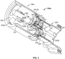
- a fluid source assembly may include (a) a source tank (not shown), (b) a nozzle 801 and (c) a hose or conduit 850 extending between the source tank and nozzle.
- a fluid source assembly is a natural gas filling station.
- a fluid destination assembly may include (a) a destination tank 870, (b) a receptacle 860, and (c) a hose or conduit (not shown) extending between the destination tank and receptacle.
- a fluid destination assembly is a vehicle configured to store natural gas.
- Figures 1 to 8 show first embodiments of a nozzle 200 and a receptacle 300.
- Nozzle 200 is configured to couple with and decouple from receptacle 300.
- fluid may flow from the source tank (not shown), through the source hose or conduit 850, through nozzle 200, through receptacle 300, through a destination hose or conduit (not shown), and into a destination tank 870.
- Nozzle 200 is configured to accept fluid from the source hose or conduit 850 via inlet void 201a and to expel the fluid into receptacle 300 through one or more outlet voids 202a (also called outlet ports).
- Inlet void 201a may be in constant fluid communication with outlet voids 202a, even prior to coupling between nozzle 200 and receptacle 300.
- fluid cannot access receptacle 300 via outlet voids 202a because nozzle 200 is only partially coupled with receptacle 300.
- fluid may access receptacle 300 via outlet voids 202a because nozzle 200 is fully coupled with receptacle 300.
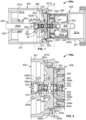
- nozzle 200 includes a main body 201, a probe 202, 203, 204, 205, 207, and a link or lever 206.
- the probe includes a nozzle check assembly 207.
- the probe is configured to slide or longitudinally translate/move with respect to main body 201.
- the probe includes a spring seat 202 (also called a body or a dispenser), a poppet engager 203 (also called a body or a plate), a packing 204, fasteners 205 securing spring seat 202 with poppet engager 203, and nozzle check assembly 207.
- Nozzle check assembly 207 is configured to equalize pressure of nozzle void 202b (and other voids in fluid communication with nozzle void 202b) with receptacle void 301e prior to complete coupling between nozzle 200 and receptacle 300. Such pressure equalization advantageously reduces the amount of effort required to fully couple nozzle 200 with receptacle 300, which is discussed in detail below.
- Spring seat 202 is cylindrical and includes a first portion (not labeled) and a second portion (not labeled).
- the first portion defines a cylindrical central void 202b and oval-shaped outlet voids 202a (also called outlet ports or window ports). Outlet voids 202a may be any suitable shape.
- the second portion defines a cylindrical central void 202c for accommodating nozzle check assembly 207 and a cylindrical central void 202d for constantly fluidly communicating void 202b with void 202c.
- Outlet voids 202a may be windows defined through an outer perimeter of spring seat 202 such that reference lines perpendicular to the longitudinal axis of nozzle 200 and extending through each of outlet voids 202a intersect a longitudinally centerline of void 202b.
- Voids 202a, 202b, 202c, 202d (and optionally void 201a - if a nozzle valve (not shown) is disposed upstream of void 201a e.g., in handle 800 or in hose 850) may be in constant fluid communication, both prior to and during full coupling.
- spring seat 202 includes a step or shoulder (not labeled) defining an annular recess for receiving packing 204.
- Poppet engager 203 is cylindrical and defines a central void (not labeled) for accommodating nozzle check assembly 207. As shown in Figure 2 , the central void includes a cylindrical portion (not labeled) and a partially conical portion (not labeled). Poppet engager 203 includes a sealing surface 203a (also called a valve seat) for nozzle check assembly 207. Poppet engager 203 includes a ring-shaped and longitudinally extending protrusion 203b extending from one end. Protrusion 203b contributes to defining the partially conical portion of the central void of poppet engager 203.
- Packing 204 may include a circumferential spring 204b. Operation of circumferential springs in packing material is discussed below with reference to Figures 18 to 25 .
- Spring 204b is surrounded by packing material (e.g., polymeric material) on three sides.
- a fourth side i.e., the side facing spring seat 202 is open (i.e., at least partially open) to enable fluid admission into circumferential spring 204b.
- packing 204 Prior to full coupling, packing 204 is radially compressed between spring seat 202 and main body 201. Packing 204 thus prevents fluid from leaking between main body 201 and spring seat 202 prior to full coupling. Upon full coupling, and as shown in Figure 7 , packing 204 no longer contacts main body 201 and thus does not substantially effect fluid flow.
- Packing 204 includes an inner portion 204a, which is discussed below with reference to fasteners 205.
- Fasteners 205 extend through poppet engager 203 and are threaded into blind bores defined in spring seat 202. Fasteners 205 bind poppet engager 203 to spring seat 202. As shown in Figure 2 , an inner portion 204a of packing 204 extends into an annular groove (not labeled) defined between poppet engager 203 and spring seat 202. Inner portion 204a is compressed or squeezed between poppet engager 203 and spring seat 202 by virtue of fasteners 205. This compression or squeeze retains packing 204 in the annular groove upon full coupling ( Figure 7 ), where main body 201 no longer exerts a radially inward force on packing 204.
- Link or lever 206 may be moveable and/or rotatable (not shown) between an open position and a closed position. Link or lever 206 may be configured to actuate the two-way valve (not shown and previously discussed) disposed in the source hose or conduit 850, the handle 800, or in nozzle 200. When the valve is open, fluid flows from the source hose or conduit to pressurize voids 201a, 202a, 202b, 202c, 202d. Link or lever 206 may be configured to apply a longitudinal force on spring seat 202 to move main body 201, spring seat 202, and poppet engager 203 toward receptacle 300.
- nozzle 200 may include an outer body 506 with one or more coupling arms 506a.
- outer body 506 may include other kinds of couplers such as ball bearings.
- Coupling arms 506a grip receptacle 300 to secure outer body 506 with respect to receptacle 300.
- link or lever 206 (which may correspond to link or lever 504b of Figure 10 ) may be part of an assembly 504 including a force originator 504a. Force originator 504a may apply a longitudinal force to link or lever 206 to longitudinally translate main body 201, spring seat 202, and poppet engager 203.
- main body 201 and spring seat 202 may be configured to engage and disengage. When main body 201 and spring seat 202 are engaged, both features longitudinally translate as a unit. When main body 201 and spring seat 202 are disengaged, spring seat 202 may longitudinally translate inside of, and with respect to, main body 201. As discussed below, one of main body 201 and spring seat 202 may include an annular tab or protrusion (not shown) and the other of main body 201 and spring seat 202 may define an annular groove or recess for receiving the annular tab (not shown). Additionally, and as discussed below, one of outer body 506 and main body 201 may include a projection (not shown) and the other of outer body 506 and main body 201 may include a step or shoulder configured to contact the projection (not shown).
- spring seat 202 and main body 201 longitudinally translate as a unit until main body 201 is stopped against outer body 506 by virtue of the projection contacting the step or shoulder.
- the annular tab may disengage from the annular groove or recess, thus enabling spring seat 202 to further longitudinally translate while main body 201 remains stopped.
- main body 201 may remain stopped until the annular tab engages the annular groove or recess.
- main body 201 and spring seat 202 may retract from receptacle 300 as a unit.
- nozzle check assembly 207 is configured to engage a receptacle check assembly 307. Engagement equalizes nozzle fluid pressure with receptacle fluid pressure, which often reduces the effort required to fully couple nozzle 200 and receptacle 300. More specifically, prior to coupling, pressure in receptacle 300 (e.g., pressure in receptacle void 301e) is typically greater than pressure in nozzle 200 (e.g., pressure in nozzle 202b). Because nozzle 200 is inserted into receptacle 300 during coupling (see Figure 7 ), nozzle 200 reduces the volume of receptacle void 301e. Fluid in receptacle void 301e opposes this reduction in volume and thus opposes insertion of nozzle 200 into receptacle 300.
- pressure in receptacle 300 e.g., pressure in receptacle void 301e
- pressure in nozzle 200 e.g., pressure in nozzle void 301e
- Check assemblies 207, 307 reduce fluid pressure in receptacle void 301e by transferring fluid in receptacle void 301e to nozzle void 202b prior to nozzle 200 reducing volume of receptacle void 301e. As such, fluid in receptacle void 301e is at a lower pressure and insertion of nozzle 200 into receptacle 300 requires less force.
- nozzle check assembly 207 is disposed in centers of spring seat 202 and poppet engager 203.
- Nozzle check assembly 207 includes a check spring 208, a spring stop 209, a check 210 (also called a poppet), and a seal assembly 211 (also called a groove and seal assembly).
- Check spring 208 sits between spring seat 202 and spring stop 209.
- Check spring 208 biases check 210 to a closed position where fluid communication is disabled between nozzle void 202c and receptacle void 306a (or ambient atmosphere if receptacle 300 is absent).
- Spring stop 209 defines a threaded blind bore (not labeled) through which check 210 is disposed.
- Check 210 may be threaded into the blind bore. Alternatively, check 210 may be unfastened to spring stop 209 and the blind bore may be unthreaded.
- spring stop 209 includes an outer annular flange 209a directly disposed between check spring 208 and an outer portion of check 210.
- nozzle check 210 includes a cylindrical engaging portion 210a, a partially conical aligning portion 210b, an annular seal 210c, and a cylindrical securing portion 210d.
- Engaging portion 210a is configured to engage receptacle check 310.
- Aligning portion 210b, in conjunction with spring stop 209, is configured to compress and retain seal 210c thereby biasing seal 210c into compressive engagement with valve seat or sealing surface 203a when nozzle check assembly 207 is closed.
- Securing portion 210d is configured to sit within the blind bore defined in spring stop 209.
- Securing portion 210d may be threadably received in, or otherwise fixed to, spring stop 209 to enhance compression of seal 210c.
- Engaging portion 210a, aligning portion 210b, and securing portion 210d may be metallic while seal 210c may be polymeric (e.g., a plastic).
- Figure 8 shows nozzle check 210 engaging receptacle check 310 while seal assembly 211 is disengaged from receptacle 300, in practice, and as discussed below, seal assembly 211 at least partially engages receptacle 300 before nozzle check 210 and receptacle check 310 begin moving.
- Seal assembly 211 includes an annular seal affixed to the annular protrusion of poppet engager 203. Seal assembly 211 is configured to sealingly and compressively engage a sealing surface 3060 of receptacle 300 to discourage fluid leak between an interface gap 101 between nozzle 200 and receptacle 300. As shown in Figure 8 , a radially outward surface of seal assembly 211 may be slanted with respect to the longitudinal axis to match sealing surface 3060, which may be similarly slanted with respect to the longitudinal axis. Sealing surface 3060 may include a minor chamfer 3060a disposed only about a portion of sealing surface 3060. Minor chamfer 3060a may draw sealing surface 211 toward sealing surface 3060.
- Nozzle 200 and/or receptacle 300 may be sized, dimension, and/or configured such that at least a portion of seal assembly 211 circumferentially seals against at least a portion of sealing surface 3060 before any of nozzle check assembly 207 and receptacle check assembly 307 open.
- Nozzle 200 and/or receptacle 300 may be further sized, dimension, and/or configured such that seal assembly 211 fully seals (e.g., has sealed along the full longitudinal length of outer chamfer 211a) after nozzle check assembly 207 has opened, but before receptacle check assembly 310 has opened.
- receptacle 300 includes a cylindrical main body 301, a spring seat 302, a stem 303, a spring 304, a packing 305, a poppet 306, and a receptacle check assembly 307.
- receptacle check assembly 307 is configured to engage nozzle check assembly 207 to equalize pressure in receptacle void 301e with pressure in nozzle void 202b prior to full coupling.
- poppet 306 is configured to disengage from main body 301 to enable nozzle 200 to enter receptacle void 301e and thereafter release fluid into receptacle void 301e via voids 202a.
- nozzle 200 engages packing 305 to prevent leakage between nozzle 200 and receptacle 300.
- Main body 301 includes a first portion 301a threaded to a second portion 301b.
- packing 305 includes a radially outward portion 305a compressed and thereby retained between first portion 301a and second portion 301b.
- An inner surface 3010b of second portion 301b is smooth, cylindrical and configured to engage and admit the smooth and cylindrical outer surface of nozzle main body 201.
- the inner surface of second portion 301b and the outer surface of nozzle main body 201 may be polished to excellent surface finishes, such that the inner surface of second portion 301b and the outer surface of nozzle main body 201 have higher grade surface finishes (i.e., are more polished) than other components in nozzle 200 and receptacle 300.
- First portion 301a includes a partially conical valve seat or sealing surface 3010 configured to sealingly engage poppet 306.
- Main body 301 defines void 301e for directly receiving fluid expelled from nozzle voids 202a, as shown in Figure 7 .
- Spring seat 302 defines a longitudinally extending central cylindrical void (not labeled) for slideably receiving stem 303.
- Spring seat 302 further defines a plurality of longitudinally extending kidney-shaped outer voids 302a (outer voids 302a may be any suitable shape) for carrying fluid from void 301e to the destination house or conduit.
- Spring seat 302 is fixed with respect to main body 301. As shown in Figure 3 , spring seat 302 may be integral with main body 301. If non-integral with main body 301, spring seat 302 may be threaded or otherwise secured (not shown) to main body 301.
- Stem 303 is configured to enable poppet 306 and thus check assembly 307 to longitudinally move, slide, or translate with respect to main body 301.
- Stem includes a cylindrical extension portion 303a, a nut or stop 303b, and a head 303c.
- Extension portion 303a is configured to slide within the central void defined in spring seat 302.
- One end (not labeled) of poppet 306 contacts nut or stop 303b.
- Head 303c has an outer diameter less than an outer diameter of nut or stop 303b and may be threaded into poppet 306.
- a longitudinal end of head 303c is flat and serves as a seat for check spring 308.
- the inner threads (not labeled) of poppet 306 are longitudinally longer than head 303c to enable user adjustment of the position of head 303c and thus compression of check spring 308.
- head 303c has been properly positioned, nut 303b is locked into position to discourage movement of head 303c along the inner threads of poppet 306.
- head 303c is not threaded or otherwise affixed to poppet 306 and thus nut or stop 303b prevents poppet 306 from sliding toward spring seat 302 along stem 303.
- Spring 304 is directly disposed between spring seat 302 and poppet 306. Because spring seat 302 cannot move toward the destination hose or conduit (not shown, but disposed at the longitudinal end of body 301 adjacent spring seat 302), spring 304 biases poppet 306 to a closed position where poppet 306 sealingly engages valve seat or sealing surface 3010.
- Packing 305 includes outer radial and annular portion 305a compressively retained between first and second portions 301a, 301b of main body 301.
- Packing 305 includes a circumferential spring 305b
- circumferential springs are discussed below with reference to Figures 18 to 25 .
- packing material e.g., polymeric material
- packing 305 Prior to coupling (not shown) and during some initial stages of coupling (see Figures 1 to 5 ), packing 305 is compressed between main body 301 and poppet 306 to prevent fluid leakage between main body 301 and poppet 306. As shown in Figures 6 and 7 , the cylindrical outer surface of nozzle main body 201 eventually displaces poppet 306 from packing 305 and packing 305 becomes compressed between receptacle main body 301 and nozzle main body 201. In this position, packing 305 prevents fluid leakage between receptacle main body 301 and nozzle main body 201.
- Poppet 306 is configured to move, slide, or translate between (a) a closed position where poppet 306 engages packing 305 (b) an open position where poppet 306 is disengaged from packing 305.
- Figure 1 shows the closed position
- Figure 7 shows the open position.
- Poppet 306 may include a partially conical inner surface 3060, chamfer 3061, and an annular groove 3062.
- Annular groove 3062 may be fluidly connected with one or more channels (not shown) defined in poppet 306, which enable fluid in receptacle void 301e to reach the inside of circumferential spring 305b when poppet 306 is closed.
- Partially conical inner surface 3060 may stop against inner surface 3010 of receptacle main body 306 when poppet 306 is in the closed position.
- Poppet 306 defines a partially conical void 306a, a cylindrical void 306b, a cylindrical void 306c, a main void 306d with a first partially conical portion (not labeled) and a second cylindrical portion (not labeled), and a cylindrical void 306e.
- cylindrical void 306e may be defined by threads for receiving head portion 303c of stem 303.
- Voids 306a to 306e may be centrally disposed in poppet 306 (i.e., central axes of the voids may be collinear with a central axis of receptacle 300 and/or with a central axis of poppet 306).
- Poppet 306 may further define one or more communicating voids (e.g., cross drillings 480 of Figure 10 ) fluidly communicating void 306d with void 301e.
- Poppet 306 includes an annular and partially conical valve seat or sealing surface 3063 for engaging check 310 and closing check assembly 307.
- Poppet 306 includes a step or shoulder 3064 for stopping longitudinal movement of stem 303 toward check 310.
- receptacle check assembly 307 is configured to engage nozzle check assembly 207 to fluidly communicate receptacle void 301e with nozzle void 202b. Such fluid communication often reduces pressure in receptacle void 301e.
- the inclusion of receptacle check assembly 307 and nozzle check assembly 207 represents an improvement over at least some known nozzles and receptacles.
- force required to open a receptacle poppet with a nozzle is determined by fluid force acting on the receptacle poppet plus other forces (e.g., spring forces). Fluid force acting on the receptacle poppet is equal to surface area of the poppet exposed to fluid multiplied by fluid pressure. After the receptacle has been opened and the pressure between the receptacle and the nozzle has equalized, the force required to further open the receptacle is determined by only the other forces (i.e., not fluid pressure acting on the poppet).
- receptacle check or poppet 310 has a much smaller surface area than receptacle poppet 306. As a result, the fluid force acting on receptacle check or poppet 310 is much smaller than the fluid force acting on receptacle poppet 306.
- Embodiments of the present disclosure open receptacle check or poppet 310 before opening receptacle poppet 306.
- receptacle check assembly 307 (all check assemblies disclosed herein may be referred to as pilot assemblies) includes a check spring 308, a spring stop 309, and a check 310 (all checks disclosed herein may be referred to as poppets or pilots).
- Check assembly 307 may be centrally disposed in poppet 306 and/or main body 301 such that nozzle check assembly 207 is aligned with receptacle check assembly 307 during the coupling process.
- Check spring 308 is directly disposed between head portion 303c of stem 303 and spring stop 309. Check spring 308 biases check 310 into a closed position where check 310 is in sealing engagement with valve seat or sealing surface 3063 of poppet 306. The closed position disables fluid communication of (a) voids 306a, 306b, and 306c with (b) voids 306d, 306e, and 301e.
- Spring stop 309 defines a threaded blind bore (not labeled) through which check 310 is disposed.
- Check 310 may be threaded into the blind bore.
- check 310 may be unfastened to spring stop 309 and the blind bore may be unthreaded.
- Spring stop 309 like spring stop 209, includes an outer annular flange (not labeled) directly disposed between check spring 308 and an outer portion of check 310.
- receptacle check 310 includes a cylindrical engaging portion 310a, a partially conical aligning portion 310b, an annular seal 310c, and a cylindrical securing portion 310d.
- Engaging portion 310a is configured to engage nozzle check 210.
- a circular longitudinal end (not labeled) of receptacle engaging portion 310a may have the same surface area and diameter of the circular longitudinal end (not labeled) of nozzle engaging portion 210a.
- Aligning portion 310b in conjunction with spring stop 309, is configured to compress and retain seal 310c, thereby biasing seal 310c into compressive contact with valve seat or sealing surface 3063 when receptacle check assembly 307 is closed.
- Securing portion 310d sits within the blind bore defined in spring stop 309. Securing portion 310d may be threadably received in, or otherwise fixed to, spring stop 309 to enhance compression of seal 310c.
- Engaging portion 310a, aligning portion 310b, and securing portion 310d may be metallic while seal 310c may be polymeric (e.g., a rubber, a plastic).
- spring stop 309 and check 310 of receptacle 300 may be identical to spring stop 209 and check 210 of nozzle 200.
- Receptacle check spring 308 may have a greater spring constant than nozzle check spring 208 to cause nozzle check assembly 207 to open before receptacle check assembly 307.
- FIG. 4 shows a first coupling stage 100a, which represents a beginning of the coupling process and an end of the decoupling or retracting process.
- Figures 1 to 3 and 8 also show the first coupling stage 100a.
- Figure 5 shows a second coupling stage 100b, which occurs after first coupling stage 100a during coupling and before first coupling stage 100a during decoupling.
- Figure 6 shows a third coupling stage 100c, which occurs after second coupling stage 100b during coupling and before second coupling stage 100b during decoupling.
- Figure 7 shows a fourth coupling stage 100d, which represents an end of the coupling process and a beginning of the decoupling process.
- Figures 4 to 7 do not show movement of check assemblies 207, 307.
- nozzle outer body 506 includes one or more latches (also called coupling arms) 506a that bind nozzle outer body 506 to a receptacle main body.
- nozzle check 310 may begin to engage receptacle check 310 or may be slightly spaced therefrom. As shown in Figure 4 , poppet engager 203 is spaced from poppet 306 by interface gap 101. Neither nozzle check 207 nor receptacle check 307 is open at this stage. The user continues to press nozzle main body 201 into receptacle main body 301 until seal assembly 211 circumferentially engages at least a portion of inner surface 3060 of poppet 306.
- spring seat 202 may include a radially outwardly extending flexible tab (not shown) configured to engage an annular inner recess of nozzle main body 201 (not shown). Engagement between the flexible tab and the annular inner recess may cause main body 201 to longitudinally extend with spring seat 202 until main body 201 contacts a hard stop (discussed above and further discussed below). At that point, the flexible tab may disengage from main body 201 to enable relative movement between spring seat 202 and main body 201. Alternatively, the flexible tab may radially inwardly extend from main body 201 into an outer radial recess defined in spring seat 202 (not shown).
- receptacle check 310 forces nozzle check 210 open while receptacle check 310 remains closed. More specifically, receptacle check 310 applies a first force against nozzle check 210 and nozzle check 210 applies a second, opposite force against receptacle check 310. Receptacle check 310 transmits the first force to receptacle check spring 308, which applies the force to stem head portion 303c. When stem head portion 303c is threaded into poppet 306, as is preferred, stem 303 does not move toward spring seat 302 by virtue of a counterforce applied by main spring 304 to poppet 306 (which has a larger spring constant than receptacle check spring 308).
- Another feature prevents stem 303 from longitudinally sliding toward spring seat 302.
- This other feature may be a stopping tab (not shown) disposed in void 306e or a moveable lever configured to occupy a stopping position that arrests longitudinal movement of stem 303 toward spring seat 302.
- receptacle check 310 remains closed while nozzle check 210 disengages from valve seat or sealing surface 203a, thus opening nozzle check assembly 207. Fluid communication is now enabled between nozzle void 202b and receptacle void 306b.
- nozzle check 210 stops moving toward spring seat 202.
- the stop may be provided by an annular stop (not shown) disposed in spring seat 202.
- the stop may be provided by the enhanced compression of nozzle check spring 208.
- nozzle check assembly 207 applies sufficient force against receptacle check assembly 307 to overcome the biasing force of receptacle check spring 308 and disengage receptacle check 310 from valve seat or sealing surface 3063. It should thus be appreciated that nozzle 200 and receptacle 300 are configured such that nozzle check assembly 207 and receptacle check assembly 307 are both opened prior to, or at the point of, firm contact between poppet engager 203 and poppet 306.
- fluid communication between receptacle void 301e and nozzle void 202b is enabled by way of receptacle void 306b. Fluid flows from receptacle void 301e into nozzle void 202b (or from nozzle void 202b into receptacle void 301e if fluid pressure in nozzle void 202b exceeds fluid pressure in receptacle void 301e). Because fluid pressure in receptacle void 301e is typically greater than fluid pressure in nozzle void 202b, the pressure in receptacle void 301e will typically decrease.
- poppet engager 203 is firmly contacting poppet 306 and thus both of nozzle check assembly 207 and receptacle check assembly 307 are open.
- Figures 4 to 7 omit movement of nozzle check assembly 207 and receptacle check assembly 307.
- the user may wait for the pressure in receptacle void 301e to fully equalize with the pressure in nozzle void 202b by maintaining the position of Figure 5 .
- the user may continue to insert nozzle 200 further into receptacle 300.
- Poppet engager 203 pushes poppet 306 toward receptacle spring seat 302, causing surface 3060 of poppet 306 to disengage from surface 3010 of receptacle main body 301.
- packing 305 continues to sealingly engage poppet 306.
- poppet 306 disengages from packing 305 while receptacle main body 201 engages packing 305. It should thus be appreciated that packing 305 is perpetually radially sealed against at least one of poppet 306 and receptacle main body 201.
- An alternative embodiment of packing 305 is discussed below with reference to Figures 18 to 25 .
- Nozzle main body 201 stops in the position of Figure 6 .
- the stop may be provided by a stopping feature (not shown) of nozzle 200 engaging a corresponding stopping feature (not shown) of receptacle 300.
- the stop may be provided between engagement between nozzle main body 201 and the outer body 506 of nozzle 200 (nozzle 200 corresponds to nozzle 500 in Figure 10 ).
- the outer body 506 may include an inner step or shoulder serving as a stop for a radially outwardly extending flange of nozzle main body 201.
- the outer body 506 may include an outer step or shoulder serving as a stop for a radially inwardly extending flange of the nozzle outer body 506.
- Nozzle 200 may include a stopping feature (not shown) preventing ingress of spring seat 202 past the position shown in Figure 7 .
- the user actuates lever or link 206 (or another feature) to fluidly communicate nozzle void 202b with the source hose or conduit (not shown). Fluid now flows from nozzle 200 into receptacle 300.
- Decoupling occurs in the reverse order.
- nozzle check assembly 207 and receptacle check assembly 307 both remain open at least until poppet engager 203 is no longer in firm contact with poppet 306.
- pressure in nozzle void 202b is transferred into receptacle void 301e, thus reducing the difficulty of retracting spring seat 202 into nozzle main body 201.
- Receptacle check assembly 307 closes before nozzle check assembly 207.
- the volumetric sum of fluid vented into atmosphere upon decoupling is less than 10, 5, or 2 cubic centimeters. According to an especially preferred embodiment, the volumetric sum of fluid is less than or equal to 1 cubic centimeter. Fluid vented during decoupling by existing receptacles is often 25 cubic centimeters.
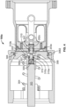
- Figure 9 shows a second embodiment of a receptacle 400.
- Figures 10 to 12 show a second embodiment of a nozzle 500 configured to couple with receptacle 400. It should be appreciated that nozzle 500 of Figures 10 to 12 may be include a nozzle check assembly (not shown and discussed below).
- receptacle 400 includes a main body 401, a spring seat 410, a first spring 415, a first stem 420, a first poppet 425, a first valve seat 430, a packing 435, a second spring 440, a second stem 445, a second poppet 450, a packing 460, and a check assembly 470.
- Receptacle check assembly 470 is configured to operate similar to receptacle check assembly 307. More specifically, receptacle check assembly 470 is configured to engage nozzle check assembly (not shown, but similar to nozzle check assembly 207) to equalize pressure of receptacle 400 with pressure of nozzle 500.
- Main body 401 includes a first portion 402 affixed (e.g., threaded or fastened) to a second portion 403 and a third portion 404 affixed (e.g., threaded) to second portion 403.
- First portion 402 defines an outlet port 405.
- Third portion 404 defines an inlet port 406.
- Spring seat 410 may be threaded to first portion 402 or may be integral with third portion 402.
- Spring seat 410 defines longitudinally extending voids 411 for enabling fluid flow across spring seat 410 and toward outlet port 405.
- Spring seat 410 defines a central void (not labeled) for slideably receiving first stem 420.
- First spring 415 sits directly between spring seat 410 and poppet 425.
- First main spring 415 biases poppet 425 to a closed position where poppet 425 sealingly and compressively engages valve seat 430.
- Stem 420 is affixed (e.g., integral or threaded) to poppet 425.
- Stem 420 includes a cylindrical first portion 421 for moving or sliding within spring seat 410.
- Stem 420 includes a cylindrical second portion 422 for stopping against spring seat 410 and thereby arresting longitudinal translation of stem 420 and poppet 425 toward outlet port 425.
- Poppet 425 is affixed (e.g., integral or threaded) to poppet 425.
- Poppet 425 defines an annular recess 426 for receiving first spring 415.
- Poppet 425 includes a partially conical outer surface 427 for sealingly engaging valve seat 430.
- Stem 420 and poppet 425 define a longitudinally extending cylindrical blind bore 428 for slideably receiving second stem 445.
- First spring 425 retains poppet 425 in the closed position until (a) second stem 445 contacts inner stop 429 or (b) fluid pressure exerted on outer surfaces of poppet 425 biasing poppet 425 toward spring seat 410 exceed the biasing force of first spring 415.
- second stem 445 may be sized to never contact inner stop 429.
- Valve seat 430 includes a cylindrical body 431 and an annular packing 432. Annular packing 432 is retained in position by virtue of being compressed between cylindrical body 431 and first portion 402 of main body 401. Cylindrical body 431 is retained in position by virtue of annular packing 432 and second spring 440. Alternatively, cylindrical body 431 is threaded into second portion 402 of main body 401.
- Annular packing 432 includes a first annular portion 432a and a second annular portion 432b.
- First annular portion 432a is compressed between cylindrical body 431 and an inner ledge (not labeled) of second portion 402 of main body 401.
- Second annular portion 432b serves as a valve seat or sealing surface for first poppet 425.
- Cylindrical body 431 defines inner voids 433 for enabling fluid flow from inlet port 406 to first poppet 425.
- Cylindrical body 430 includes an annular upper surface 434a partially defining inner void 433 and serving as a seat for second spring 440.
- Cylindrical body 431 includes guiding portion 434b defining a longitudinally extending cylindrical void (not labeled) for receiving second stem 445. Guiding portion 434b protrudes above annular upper surface 434a.
- Packing 435 is annular and sits in an annular recess defined in second portion 403 of main body 401. Packing 435 is compressed between first portion 402, second portion 403, and valve seat 430. Packing 435 thus discourages fluid leak (a) between the interface of first portion 402 and second portion 403 and (b) between second portion 402 and valve seat 430. Packing 435 may include a circumferential spring (not labeled) and the packing may be configured to admit fluid into the circumferential spring.
- Second stem 445 is cylindrical and affixed (e.g., integral or threaded) to second poppet 450.
- Second spring 440 sits between valve seat 430 and second poppet 450. Because valve seat 430 is fixed in place, second spring 440 biases second poppet 450 to a closed position.
- Second poppet 450 includes an annular outer surface 451 configured to engage an outer annular protrusion 452 of second portion 403. Outer annular protrusion 452 thus serves as a secondary valve seat or secondary sealing surface for second poppet 450.
- a primary valve seat or sealing surface (not labeled) may lie directly below protrusion 452.
- Figure 9 shows second poppet 450 including an annular outward protrusion 453, protrusion 453 may be absent to enable poppet 450 to move or slide toward outlet port 405. Alternatively, protrusion 453 may be present and second poppet 450 may be polymeric, thus enabling main body protrusion 452 to inwardly compress poppet protrusion 453.
- Poppet 450 defines a central blind bore (not labeled) for accommodating check assembly 470.
- Poppet 450 includes an ring 454 fixed inside of the central blind bore. Ring 454 may be integral with poppet 450 or may be threaded into the central blind bore.
- Poppet 450 defines cross drillings 480 (see Figure 10 ) fluidly communicating the central void with inlet port 406.
- second spring 440 biases poppet 450 to a closed position whereby poppet 450 sealingly engages main body protrusion 452. Because second stem 445 is affixed to second poppet 450, second spring 440 biases stem 445 away from stop 429 of first stem and poppet 420, 425.
- Packing 460 includes an annular radially outwardly extending portion 461 compressed and retained between second portion 403 and third portion 404. Packing 460 includes a circumferential spring 462 biasing packing 460 into compressive contact with an outer surface (not labeled) of second poppet 450. As with all circumferential springs disclosed herein, circumferential spring 462 may be disposed in a pocket or groove defined in the packing material of packing 460, thus enabling fluid to occupy spring 462 (when spring 462 is exposed to fluid).
- Receptacle check assembly 470 includes a check spring 471, a spring stop 472, and a check 473.
- Check 473 may include some or all of the features of receptacle check 310.
- Check 473 may include a cylindrical engaging portion 473a, a partially conical aligning portion (not shown), an annular seal 473b, and a cylindrical securing portion (not shown). The partially conical aligning portion and the cylindrical securing portion may resemble the corresponding features of receptacle check 310.
- Check spring 471 biases annular seal 473b of check 473 into sealing engagement with ring 454.
- nozzle 500 includes a main body 501, a dispenser 502, a poppet engager 503, a link assembly 504, a packing 505, and an outer body 506.
- Nozzle 500 is configured to engage receptacle 400 and enable transmission of fluid from the source (not shown) into receptacle 400.
- Outer body 506 includes one or more couplers 506a (e.g., latches or ball bearings) configured to secure receptacle 400 with respect to outer body 506.
- a combination of dispenser 502, poppet engager 503, packing 505, and a nozzle check assembly (if present) may be referred to as a probe.
- outer body 506 is also used to describe features of nozzle 200.
- Main body 501 is annular and surrounds dispenser 502 and poppet engager 503 prior to coupling and during a first coupling step 600a, as shown in Figure 10 .
- Figure 10 only shows main body 501 surrounding one side of dispenser 502 and poppet engager 503, main body 501 circumferentially surrounds all sides of dispenser 502 and poppet engager 503.
- Dispenser 502 is similar to spring seat 202 of nozzle 200. Dispenser 502 defines outer voids 502a and a cylindrical inner void 502b. Outer voids 502a are windows to inner void 502b, similar to voids 202a of nozzle 200.
- Poppet engager 503 is a cylindrical plate secured to dispenser 502. Poppet engager 503 includes a cylindrical protrusion 503a extending from a flat annular end 503b.
- Link assembly 504 includes force originator 504a, a link or lever 504b, and a force applicator 504c. Force applied to force originator 504a is transmitted via link or lever 504b to force applicator 504c to move main body 501 and/or dispenser 502. Force applicator 504c is connected to dispenser 502. Link or lever 206 of nozzle 200 may correspond to link or lever 504b of nozzle 500, such that nozzle 200 is longitudinally translated similar to nozzle 500,
- Dispenser 502 may include an annular tab (not shown) and main body 501 may define an annular groove (not shown) for the annular tab. Dispenser 502 thus applies longitudinal force to main body 501 until main body 501 reaches a maximum longitudinal extension (see Figures 11 and 12 ). The annular tab may then disengage from the annular groove, thus enabling receiver 502 to move or slide with respect to main body 501 (see Figure 12 ).
- Packing 505 may be configured similar to packing 204 of nozzle 200 and include (a) an annular inward portion (not labeled) compressed between dispenser 502 and poppet engager 503 and (b) a circumferential spring (not shown) biasing packing 505 into compressive engagement with main body 501. As with all circumferential springs disclosed herein, the circumferential spring of packing 505 may be only partially surrounded by packing material to enable fluid admission into the circumferential spring.
- Nozzle 500 may include a check assembly (not shown) similar to nozzle check assembly 207. Nozzle 500 may be configured to include some or all of the features of nozzle 200 shown in box 2 of Figure 1 , including nozzle check assembly 207. As a result, dispenser 502 may act as a spring plate for the check spring, similar to spring plate 202. Dispenser 502 may define voids fluidly communicating the nozzle check assembly with inner void 502b.
- FIG. 10 shows a first stage 600a.
- Figure 11 shows a second stage 600b.
- Figure 12 shows a third stage 600c.
- a coupling process between nozzle 500 and receptacle 400 begins at first stage 600a and ends at third stage 600c.
- a decoupling or retraction process between nozzle 500 and receptacle 400 begins at third stage 600c and ends at first stage 600a.
- a user secures nozzle outer body 506 to receptacle 400 via one or more latches 506a.
- nozzle 500 does not include a check assembly
- the user presses protrusion 503a against receptacle check 473 before poppet engager 503 firmly engages poppet 450.
- Protrusion 503a opens receptacle check 473.
- Fluid in inlet port 406 vents to ambient atmosphere via the gap between poppet engager 503 and poppet 450.
- nozzle 500 does include a check assembly
- the user presses the nozzle check assembly against receptacle check assembly 470.
- Poppet engager 503 has not yet firmly engaged poppet 450.
- the nozzle check assembly opens until the nozzle check stops (by virtue of a nozzle check hard stop or a nozzle check spring).
- the nozzle check then forces receptacle check assembly open. Fluid communication between inlet port 406 and nozzle inner void 502b is now enabled.
- nozzle 500 includes a check assembly
- the user continues to press nozzle 500 against receptacle 400 until poppet engager 503 firmly contacts poppet 450.
- the user may wait for pressure to equalize.
- nozzle 500 includes a check assembly
- the pressures fully or partially equalize via the check assembly. It should be appreciated that all check assemblies disclosed herein enable partial and/or full equalization when matched with a reciprocal check assembly and held open for a sufficient amount of time.
- the pressures may equalize as receptacle 400 vents fluid into ambient, but not fully equalize.
- nozzle main body 501, poppet engager 503, and dispenser 502 extend into receptacle 400.
- Receptacle packing 460 seals against nozzle main body 501.
- main body 501 stops while dispenser 502 and poppet engager 503 further extend into receptacle 400.
- Main body 501 may be stopped by nozzle outer body 506.
- a flange radially outwardly extending from main body 501 may contact an inner shoulder or step of outer body 506 or a flange radially inwardly extending from outer body 506 may contact an outer shoulder or step of main body 501.
- a user places nozzle inner void 502b in fluid communication with a source hose or conduit (e.g., by actuating a handle or pressing a button that opens a two-way valve (not shown) disposed in the source hose or conduit or disposed at an end of nozzle 500). Fluid flows from nozzle inner void 502b into receptacle inlet port 406.
- the fluid pressure in receptacle inlet port 406 may open receptacle first poppet 425.
- second stem 445 may contact stopping surface 429 to open first poppet 425. Fluid now flows from inlet port 406 to outlet port 405 and into a destination hose or conduit. Decoupling occurs in the reverse order.
- any feature of receptacle 300 may be added to, or replace, any feature of receptacle 400.
- any feature of receptacle 400 may be added to, or replace, any feature of receptacle 300.
- receptacle 300 may be modified: (a) to replace spring seat 302 with valve seat 430, (b) to treat stem 303 as stem 445, (c) to add poppet 425 in the arrangement shown in Figure 9 , (d) to add spring seat 410 as shown in Figure 9 , (e) to reconfigure main body portion 301a into portions 402 and 403, as shown in Figure 9 , and/or (f) to add packing 435, as shown in Figure 9 .
- One, some, or all of these modifications may be implemented.
- receptacle 400 may be modified: (a) to replace stem 445 with stem 303 (although still arrange stem 303 inside first poppet 425 and valve seat 430, as shown in Figure 9 ), (b) to replace poppet 450 with poppet 306, (c) to replace check assembly 470 with check assembly 307, (d) to replace main body portion 404 with main body portion 301b of main body 301, (e) to remove ring 454, and/or (f) to replace packing 462 with packing 305.
- stem 445 with stem 303 (although still arrange stem 303 inside first poppet 425 and valve seat 430, as shown in Figure 9 )
- features of receptacle 400 above replacement line R-R may be replaced with features of receptacle 300 within box 2 of Figure 1 .
- Nut 303b may also be added.
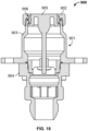
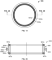
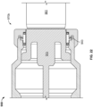
- FIGS 13 to 16 illustrate a third receptacle embodiment 700.
- Receptacle 700 includes a main body 701, a first spring seat 710, a first spring 715, a first stem 720, a first poppet 725, a valve seat 730, a second spring seat 740, a second spring 745, a second stem 750, and a second poppet 760. Portions of at least second stem 750 and second poppet 760 are not cross sectioned in Figure 13 , as is apparent in the isometric view of Figure 15 .
- Main body 701 includes a first portion 702 threaded to a second portion 703.
- Main body 701 defines a partially conical inlet port 701a and a cylindrical outlet port 701b.
- Second portion 703 includes a flat annular surface 704a and a partially conical surface 704b, which cooperate to define inlet port 701a.
- Second portion 703 includes a cylindrical surface 704c for engaging an outer circumference of poppet head 761 and a partially conical surface valve seat or sealing surface 704d for sealingly engaging a compressive packing 762 of poppet 760.
- First spring seat 710 defines a central internal void 711 for slideably receiving first stem 720.
- First spring seat 710 defines one or more voids (not shown) enabling fluid flow across first spring seat 710 (e.g., from first spring 715 to outlet 701b).
- First spring seat 710 may be threaded to main body 701.
- First spring seat 710 may be stopped against an inner shoulder 712 of main body 701.
- First spring 715 is directly disposed between first spring seat 710 and first poppet 725.
- First spring 715 biases first poppet 725 to a closed position.
- First stem 720 is secured to first poppet 725 (e.g., threaded or integral). First stem 720 is configured to slide within central internal void 711. First stem includes a step or shoulder 721 configured to stop against first spring seat 710 to arrest longitudinal movement of first poppet 725 toward outlet 701b. First stem 720 defines a central inner blind bore 722 for slideably receiving second stem 750.
- First poppet 725 includes a partially conical sealing surface 726 for engaging valve seat 730 when first poppet 725 is in the closed position.
- First poppet 725 defines a portion of inner blind bore 722.
- First spring 715 biases first poppet 725 to the closed position.
- First poppet 725 opens in response to (a) fluid pressure inside valve seat 730 exceeding the biasing force of first spring 715 or (b) second stem 750 contacting a longitudinal end of blind bore 722.
- Valve seat 730 includes an outer packing 731, an inner packing 732, and a valve seat body 733. Outer packing 731 is compressed between valve seat 730 and main body 701. Inner packing 732 is retained in valve seat 730 by virtue of major protrusion 732a and minor protrusion 732b. Major protrusion 732a contacts three different first inner surfaces of valve seat 730. Minor protrusion 732b contacts three different second inner surfaces of valve seat 730. Major protrusion 732a is perpendicular with respect to minor protrusion 732b.
- Valve seat body 733 When in the closed position, first poppet 725 compressively engages inner packing 732.
- Valve seat body 733 may be threaded to main body 701.
- Valve seat body 733 may be fixed with respect to main body 701 by virtue of opposing forces exerted by second spring 745 and outer packing 731.
- Valve seat 730 defines a cylindrical inner void (not labeled) for receiving first poppet 725, second spring seat 740, and enabling fluid flow across valve seat 730.
- Second spring seat 740 may be integral with valve seat 730. Alternatively, second spring seat 740 may rest on an inner shoulder or step (not labeled) of valve seat 730 and thus be retained by virtue of opposing forces from second spring 745 and valve seat 730. Second spring seat 740 defines a central inner void (not labeled) for slideably receiving second stem 750. Second spring seat 740 defines one or more longitudinally extending voids (not shown) for enabling fluid flow across second spring seat 740.
- Second spring 745 rests on second spring seat 740. An opposing end of second spring seat 745 contacts second poppet 760. Second spring 745 biases second poppet 760 to a closed position. Second stem 750 is secured (e.g., integral or threaded) to second poppet 760. Second stem 750 is slideably received in second spring seat 740, first poppet 725, and first stem 720.
- Second poppet 760 includes a head 761, an annular seal or packing 762, and a guide 763.
- Head 761 may be metallic while annular packing 762 and guide 763 may be polymeric.
- Guide 763 forms an annular pocket (not labeled) for receiving second spring 745.
- Guide 763 includes an outer ring 763a for engaging an inner cylindrical surface of main body to stabilize and longitudinally align second poppet 760 when second poppet 760 is in the closed position and when second poppet 760 is in an open position.
- guide 763 is annular and symmetrical about its longitudinal axis.
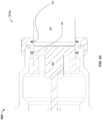
- Second poppet 760 defines a central inner blind bore 764 for receiving a check assembly 770.
- One or more voids e.g., unshown cross drillings 480
- Check assembly 770 includes a check 771, a spring stop 772, and a check spring 773.
- One end of check spring 773 contacts head 761.
- An opposing end of check spring 773 contacts spring stop 772 to bias check 771 to a closed position.
- Check 771 includes a head 771a outwardly protruding from poppet head 761.
- Check 771 includes an annular packing 771b configured to contact an inner valve seat or sealing surface 765 of second poppet 760.
- Figure 16 only shows one side of guide 763, although in practice, guide 763 may be annular and symmetrical about its longitudinal axis.
- Check assembly 770 is configured to engage a reciprocal check assembly (not shown) of a nozzle. After an outer packing of the nozzle seals against main body surface 704a, 704b, and/or 704c, the reciprocal check assembly forces receptacle check assembly 770 open, thus enabling pressure equalization between the nozzle and receptacle 700. After pressure equalization has occurred, the nozzle pushes poppet head 761 toward outlet 701b and dispenses fluid into receptacle 700. Under the pressure of fluid or due to second stem 750 contacting the end of blind bore 722, first poppet 725 opens, enabling fluid to flow from the nozzle to outlet 701b.
- a fluid source assembly may include (a) a source tank, (b) nozzle 200, 500, and (c) a hose or conduit extending between the source tank and nozzle.
- the fluid source assembly may further include a pump disposed upstream of the nozzle.
- a user may manually activate the pump to pressurize the hose or conduit with fluid from the source tank.
- the pump may be automatically activated, by a controller, when one or more sensors determine that the nozzle probe has translated a sufficient or predetermined length into receptacle 300, 400.
- the one or more sensors are thus configured to determine an amount of extension of nozzle probe into the receptacle.
- the controller may delay the pump for a set amount of time (e.g., three seconds) after the nozzle reaches the appropriate position within the receptacle.
- a controller may only enable activation of the pump once the above-described distance and/or time conditions have been satisfied.
- the controller may controller the force applied by force originator 504a to lever 206, 504.
- the controller may disable withdrawal of nozzle 500 until first poppet 425 is detected, by one or more sensors, to be closed.
- Nozzle 200, 500 may include various sensors and controls.
- the nozzle may be electrically grounded, enabling components thereof such as the poppet engager and/or the outer walls of nozzle to electrically ground the receptacle.
- the controller may confirm, with reference to one or more sensors, that the nozzle and receptacle have been electrically grounded before allowing the check assemblies of the nozzle and/or receptacle to move from their closed positions.
- the controller may confirm, with reference to one or more sensors, that the nozzle and receptacle have been electrically grounded before allowing the poppet engager to contact the poppet and/or before allowing the checks to touch.
- Leak sensors may be disposed in the nozzle to detect an undesirable flow of fluid prior to engagement with the receptacle. Leak sensors disposed around the nozzle or receptacle may detect fluid leaking past any of the annular seals.
- the nozzle may also include cycle count and service sensors such as RFID tags that enable the controller to track how many times the nozzle has engaged a receptacle.
- the receptacle may include a similar feature.
- the nozzle may include a solenoid or pneumatically operated lock to mechanically actuate the link or lever.
- a filling handle 800 is connected to a source hose or conduit 850, which is connected to a source tank (not shown).
- Filling handle 800 is coupled with receptacle 860, which is connected to tank 870 via a hose or conduit (not shown).
- Receptacle 860 includes a main body 861.
- Handle 800 includes a nozzle 801, an arm 802, a handle 803, LEDs 804, and buttons 805.
- Nozzle 801 may be any of the above-described nozzles.
- Receptacle 860 may be any of the above-described receptacles. Only the outer body of nozzle 801 is shown.
- Arm 802 is mechanically connected with the nozzle link or lever and is also mechanically connected with a motor configured to drive arm 802.
- Nozzle outer body may be an integrated grounding connection.
- LEDs 804 indicate a status of engagement between the nozzle and the receptacle.
- a first lighting pattern may indicate a pressure equalization process occurring between nozzle and receptacle check assemblies.
- a second lighting pattern may indicate the nozzle probe contacting the receptacle poppet.
- a third lighting pattern may indicate the nozzle probe being fully extended.
- a fourth lighting pattern may indicate fluid flow occurring between the nozzle and the receptacle.
- a fifth lighting pattern may indicate that the receptacle poppet has closed and that the nozzle is ready to be removed from the receptacle.
- a first button 805a may activate the pump (subject to the above-described conditions).
- a second button 805b may deactivate the pump.
- a third button 805c may cause the motor to move the arm 802 toward the receptacle to extend the nozzle (subject to the above-described conditions).
- a fourth button 805d may cause the motor to withdraw the nozzle (subject to the above-described conditions).
- FIGs 18 to 25 illustrate an alternative embodiment of a packing.
- receptacle 900 (which may correspond to any receptacle disclosed herein, including receptacles 300 and 400) includes (a) a main body 901 having a first portion 902, a second portion 903, and a third portion 904, (b) a longitudinally moveable or slideable poppet 905, and (c) a packing 906.
- Packing 906 serves as a valve seat for poppet 905.
- packing 906 includes a first circumferential spring 907a, a second circumferential spring 907b, a cylindrical spring housing 908, and a ringed protrusion or projection 909.
- Springs 907a, 907b may be (a) neutral and/or energized, or (b) radially inwardly biased and/or energized, or (c) radially outwardly biased and/or energized. When neutral, springs 907a, 907b may both radially inwardly bias packing material and radially outwardly bias packing material.
- Protrusion 909 includes a first ring 909a, a second ring 909b, and a third ring 909c.
- First and second rings 909a, 909b may be integral with spring housing 908.
- Third ring 909c may be non-integral with first and second rings 909a or may be fully integral.
- third ring 909c may slightly radially outwardly protrude from an annular groove (not labeled) defined between first and second rings 909a, 909b, in which third ring 909c is seated.
- Protrusion may be located equidistant from each spring 907a, 907b. Protrusion may be located closer to one spring 907a, 907b than the other spring 907b, 907a.
- Spring housing 908 and retainer 909 may be packing material (e.g., polymer).
- Spring housing 908 may define two three-sided annular grooves or pockets (not labeled), which receive first and second springs 907a, 907b. As with all circumferential springs disclosed herein, one side of each spring 907a, 907b may be exposed (i.e., at least partially exposed) by the annular grooves or pockets to enable fluid flow into springs 907a, 907b. This fluid flow further energizes springs 907a, 907b, enhancing compression provided by springs 907a, 907b.
- Each spring 907a, 907b may have a thickness (the thickness being the difference between the outer radius of each spring and the inner radius of each spring) greater than a thickness of the three-sided grooves or pockets before insertion of springs 907a, 907b therein to generate an interference fit between springs 907a, 907b and the grooves or pockets.
- portions 902 and 903 of receptacle main body 901 are threaded together to compress protrusion 909. Compression of first and second rings 909a, 909b retains spring housing 908 in place. Compression of third ring 909c induces radial expansion of third ring 909c, thus generating an a first outer circumferential seal 943 between main housing portion 903 and packing 906.
- the interference fit between springs and the grooves or pockets generates second and third outer circumferential seals 944 and 945.
- the inward bias of springs 907a, 907b and/or the interference fit generates first and second inner circumferential seals 941, 942 between packing 906 and poppet 905.
- Figures 21 to 25 illustrate a coupling process, including first, second, third, and fourth stages 970a, 970b, 970c, 970d between receptacle 900 and a generic nozzle 960 having a probe 961.
- a decoupling process occurs in the reverse order.
- an outer body (not shown) of nozzle 960 is latched to receptacle 900.
- Probe 961 begins touching receptacle poppet 905.
- Both inner circumferential seals 941, 942 bear on poppet 905.
- probe 961 has pushed poppet 905 a small longitudinal distance. Poppet 905 is still closed because poppet 905 is engaged with packing 906 via first inner seal 941. Poppet is no longer engaged with second inner seal 942.
- probe 961 has pushed poppet 905 a medium longitudinal distance.
- Poppet 905 is still closed because poppet 905 is engaged with packing 906 via first inner seal 941.
- Second inner seal 942 has now engaged probe 961, thus preventing fluid from leaking between main body 901 and probe 961.
- poppet 905 is no longer engaged with packing 906 and is thus open.
- Nozzle 961 has pushed poppet 905 a large distance.
- First inner seal 941 is absent.
- both first and second inner seals 941, 942 are engaged with probe 961.
- Probe 961 has pushed poppet 905 a maximum distance. A user may open nozzle 961 to flow fluid F into receptacle 900. Decoupling occurs in the reverse order.
- Packing 906 may replace some or all of the following packings: packing 204, packing 305, packing 460, packing 505. Packing 906 may only replace packings configured to contact both a nozzle and a receptacle.
- springs 907a, 907b may be (a) neutral and/or energized, (b) radially inwardly biased and/or energized, or (c) radially outward biased and/or energized.
- springs 907a, 907b may outwardly bear (due to the interference fit) on the groove or slot.
- the features retaining the packing may be reconfigured to retain packing 906.
- main body portions 301a, 301b may be reconfigured to grip protrusion 909 in the manner shown Figure 21 .
- the poppet e.g., poppet 306
- the poppet may be reconfigured, in conjunction with the features retaining the packing (e.g., the main bodies) to enable the poppet to contact a longitudinal end of packing 906 when the poppet is fully closed, as is shown in Figure 21 where poppet 905 longitudinally contacts packing 906 at spring 907b.
- a nozzle for dispensing fluid the nozzle being configured to occupy a retracted position and an extended position
- the nozzle comprising: a main body; a probe comprising a flat annular surface and a check sealing surface, the probe defining an inner void, a check void, and one or more passageways leading from the inner void to the check void; and a check assembly disposed in the check void, the check assembly comprising a check and a spring, the spring biasing the check assembly to a closed position where the check sealingly engages the check sealing surface, wherein when the check assembly is in the closed position, the check longitudinally extends beyond the flat annular surface.
- the probe comprises a poppet engager and a spring seat and the flat annular surface has an outer diameter equal to an outer diameter of the nozzle.
- the check assembly comprises a seal assembly annularly disposed about the check.
- the seal assembly is disposed beyond the flat annular surface.
- the check assembly is in the closed position, the check extends beyond the seal assembly.
- the main body when the nozzle is in the retracted position, the main body circumferentially surrounds a first portion of the probe.
- the main body when the nozzle is in the extended position, circumferentially surrounds a second portion of the probe, the second portion being less than the first portion.
- the nozzle includes an outer body comprising one or more latches configured to bind the outer body to a receptacle, wherein the main body is moveable with respect to the outer body.
- the nozzle transitions between the retracted position and the extended position, the main body translates a first distance and the probe translates a second distance, the second distance exceeding the first distance.
- one of the main body and the probe comprises one or more flexible tabs configured to engage one or more recesses defined in the other of the main body and the probe.
- the one or more flexible tabs are configured to occupy an engaged position where the one or more flexible tabs occupy the one or more recesses and a disengaged position where the one or more flexible tabs do not occupy the one or more recesses.
- the one or more flexible tabs when the one or more flexible tabs are in the engaged position, the one or more flexible tabs cause the main body and the probe to translate as a common unit and wherein the nozzle is configured such that the one or more flexible tabs disengage before the nozzle reaches the extended position.
- an outer perimeter of the probe at least partially defines one or more outlet voids, each of the one or more outlet voids being in constant fluid communication with the inner void, the main body covering each of the one or more outlet voids when the nozzle is in the retracted position and at least a portion of the one or more outlet voids protruding from the main body when the nozzle is in the extended position.
- the nozzle is configured such that as the nozzle moves from the retracted position to the extended position, the main body and the probe move together as a common unit until reaching a first distance and after the first distance, the probe moves with respect to the main body.
- the probe comprises an annular protrusion disposed in a center of the flat annular surface and the check assembly comprises a seal assembly disposed on the annular protrusion.
- an outer diameter of the seal assembly exceeds an outer diameter of the annular protrusion.
- the nozzle includes an annular packing disposed in an outer groove defined in the probe, the annular packing comprising a packing material and circumferential spring disposed in a groove defined in the packing material, the circumferential spring biasing the packing material radially outward toward the main body.
- the probe comprises one or more fasteners, the one or more fasteners causing the probe to compress at least a portion of the annular packing.
- the annular packing when the nozzle is in the retracted position, the annular packing is compressed between the probe and the main body and when the nozzle is in the extended position, the annular packing is not compressed by the main body.
- the nozzle includes an annular packing disposed in an outer groove defined in the probe, the annular packing comprises a cylindrical spring housing defining two annular spring slots and a central inner void, a ringed protrusion extending from the cylindrical spring housing, and two circumferential springs disposed in the annular spring slots.
- the nozzle includes a packing for sealing a fluid conduit, the packing comprising: a packing housing defining a longitudinally extending inner void and two annular spring grooves; a ringed projection extending from the packing housing; two circumferential springs disposed in the annular spring grooves.
- a receptacle comprising: a main body defining a main inner void; a spring seat disposed in the main body, the spring seat defining a central void; a stem at least partially disposed in the central void and at least partially disposed in the main inner void; a poppet connected to the stem, the poppet comprising an inner check sealing surface and defining a central inner check void; a spring disposed between the spring seat and the poppet, the spring at least partially occupying the main inner void, the spring biasing the poppet to a closed position; a check assembly at least partially disposed in the inner check void, the check assembly comprising a check and a check spring, the check spring biasing the check toward a closed position where the check engages the inner check sealing surface, the check protruding from the poppet when the check is in the closed position.
- the receptacle includes a packing for sealing a fluid conduit, the packing comprising: a packing housing defining a longitudinally extending inner void and two annular spring grooves; a ringed projection extending from the packing housing; two circumferential springs disposed in the annular spring grooves.
- the receptacle includes an annular packing, the annular packing comprising packing material and a circumferential spring housed in the packing material, the annular spring biasing the packing material radially inward.
- the packing when the poppet is in the closed position, the packing is compressed between the poppet and the main body.
- the annular packing comprises at least two circumferential springs housed in the packing material.
- the packing when the poppet is an open position, the packing does not contact the poppet.
- the poppet comprises a flat annular end surface.
- the poppet defines a first central void extending to the flat annular end surface.
- the poppet defines a second central void extending between the inner check void and the first central void.
- the first central void, the second central void, and the main inner void are in fluid communication.
- the nozzle includes: a nozzle main body; a nozzle probe comprising a nozzle flat annular surface and a nozzle check sealing surface, the nozzle probe defining a nozzle inner void, a nozzle check void, and one or more nozzle passageways leading from the nozzle inner void to the nozzle check void; a nozzle check assembly disposed in the nozzle check void, the nozzle check assembly comprising a nozzle check and a nozzle spring, the nozzle spring biasing the nozzle check assembly to a closed position where the nozzle check sealingly engages the nozzle check sealing surface, wherein when the nozzle check assembly is in the closed position, the nozzle check longitudinally extends beyond the nozzle flat annular surface.
- the receptacle includes: a receptacle main body defining a receptacle main inner void; a receptacle spring seat disposed in the receptacle main body, the receptacle spring seat defining a receptacle central void; a receptacle stem at least partially disposed in the receptacle central void of the receptacle spring seat, the receptacle stem being at least partially disposed in the receptacle main inner void; a receptacle poppet connected to the receptacle stem, the receptacle poppet comprising a receptacle inner check sealing surface and defining a receptacle central inner check void; a receptacle spring disposed between the receptacle spring seat and the receptacle poppet, the receptacle spring at least partially occupying the receptacle main inner void, the receptacle spring biasing
- method includes: equalizing pressure between the nozzle inner void and the receptacle main inner void by pressing the nozzle check against the receptacle check to open the nozzle check and the receptacle check; extending the nozzle into the receptacle such that the receptacle main body surrounds at least a portion of the nozzle probe; flowing fluid from the nozzle inner void into the receptacle main inner void.
- the method includes waiting for the pressure between the nozzle inner void and the receptacle main inner void to equalize before extending the nozzle into the receptacle.
- the step of inserting the nozzle into the receptacle comprises pressing the nozzle flat annular surface of the nozzle probe against the receptacle poppet.
- the receptacle poppet comprises a receptacle flat annular surface and the receptacle poppet defines a receptacle first void extending to the receptacle flat annular surface.
- the nozzle check assembly comprises a nozzle check seal.
- the method comprises inserting the nozzle check seal into the receptacle first void prior to opening the nozzle check and prior to opening the receptacle check.
- the step of equalizing pressure between the nozzle inner void and the receptacle main inner void by pressing the nozzle check against the receptacle check to open the nozzle check and the receptacle check comprises: opening the nozzle check prior to opening the receptacle check.
- the receptacle comprises a receptacle annular packing compressed between the receptacle main body and the receptacle poppet when the receptacle poppet is in the closed position, wherein when the nozzle is in the extended position, the receptacle annular packing is compressed between the nozzle main body and the receptacle main body.
- the method further includes causing the receptacle annular packing to be compressed by the receptacle main body, the receptacle poppet, and the nozzle main body for at least a moment in time.
- the receptacle comprises a receptacle additional poppet and a receptacle additional spring, the receptacle additional poppet being disposed downstream of the receptacle poppet, the receptacle additional spring biasing the receptacle additional poppet to a closed position.
- the method includes opening the receptacle additional poppet by pressurizing the receptacle main inner void.
- the method includes opening the receptacle additional poppet by causing the receptacle stem to contact a receptacle stop, the receptacle stop being connected to the receptacle additional poppet.
- the method includes: determining, via one or more sensors in electrical communication with a controller, when the nozzle reaches the extended position; via the controller, automatically causing fluid to flow from the nozzle into the receptacle when the controller determines that the nozzle has reached the extended position.
- the controller may be disposed in the nozzle.
- each of the nozzle and the receptacle include a packing for sealing a fluid conduit, the packing comprising: a packing housing defining a longitudinally extending inner void and two annular spring grooves; a ringed projection extending from the packing housing; two circumferential springs disposed in the annular spring grooves.
- a receptacle for receiving fluid, the receptacle comprising: a main body, one end of the main body defining an outlet port, an opposing end of the main body defining an inner void, and the main body comprising an inner sealing surface; a first poppet disposed in the main body, the first poppet comprising an annular seal; a first spring seat disposed in the main body; a first spring disposed between the first spring seat and the first poppet and biasing the first poppet toward a closed position where the annular seal engages the inner sealing surface; wherein, when the first poppet is in the closed position, the first poppet defines at least a portion of the inner void.
- the receptacle includes a packing for sealing a fluid conduit, the packing comprising: a packing housing defining a longitudinally extending inner void and two annular spring grooves; a ringed projection extending from the packing housing; two circumferential springs disposed in the annular spring grooves.
- the inner void is exposed to ambient atmosphere.
- the inner void is annular.
- the inner void is partially conical.
- the receptacle further includes a check assembly centrally disposed in the first poppet, the check assembly comprising a check and a check spring, the check spring biasing the check to closed position where the check contacts an inner surface of the first poppet.
- the check when the check is in the closed position, the check protrudes from the first poppet into the inner void.
- the receptacle further includes: a second spring seat disposed in the main body; a valve seat; a second poppet; a second spring disposed between the second spring seat and the second poppet, the second spring biasing the second poppet to a closed position where the second poppet contacts the valve seat.
- the receptacle includes a stem connected to the first poppet and extending through the valve seat, the first spring seat, and the second poppet.
- the main body defines a main inner void in which the first spring is disposed, the first poppet defining one or more passageways fluidly communicating the main inner void with the check spring.
- an assembly comprising a nozzle coupled with a receptacle; the nozzle being configured to occupy a retracted position and an extended position.
- the nozzle includes: a nozzle main body; a nozzle probe comprising a nozzle flat annular surface and a nozzle check sealing surface, the nozzle probe defining a nozzle inner void, a nozzle check void, and one or more nozzle passageways leading from the nozzle inner void to the nozzle check void; a nozzle check assembly disposed in the nozzle check void, the nozzle check assembly comprising a nozzle check and a nozzle spring, the nozzle spring biasing the nozzle check assembly to a closed position where the nozzle check sealingly engages the nozzle check sealing surface, wherein when the nozzle check assembly is in the closed position, the nozzle check longitudinally extends beyond the nozzle flat annular surface.
- the receptacle includes: a receptacle main body defining a receptacle main inner void; a receptacle spring seat disposed in the receptacle main body, the receptacle spring seat defining a receptacle central void; a receptacle stem at least partially disposed in the receptacle central void of the receptacle spring seat, the receptacle stem being at least partially disposed in the receptacle main inner void; a receptacle poppet connected to the receptacle stem, the receptacle poppet comprising a receptacle inner check sealing surface and defining a receptacle central inner check void; a receptacle spring disposed between the receptacle spring seat and the receptacle poppet, the receptacle spring at least partially occupying the receptacle main inner void, the receptacle spring biasing
- the assembly is configured to: equalize pressure between the nozzle inner void and the receptacle main inner void by pressing the nozzle check against the receptacle check to open the nozzle check and the receptacle check; flow fluid from the nozzle inner void into the receptacle main inner void, upon extension of the nozzle into the receptacle such that the receptacle main body surrounds at least a portion of the nozzle probe.
- each of the nozzle and the receptacle include a packing for sealing a fluid conduit, the packing comprising: a packing housing defining a longitudinally extending inner void and two annular spring grooves; a ringed projection extending from the packing housing; two circumferential springs disposed in the annular spring grooves.
- a packing for sealing a fluid conduit comprising: a packing housing defining a longitudinally extending inner void and two annular spring grooves; a ringed projection extending from the packing housing; two circumferential springs disposed in the annular spring grooves.
- each of the circumferential springs has a longitudinal axis collinear with a longitudinal axis of the packing housing.
- the packing housing only partially surrounds each of the circumferential springs such that each of the circumferential springs is exposed to fluid located outside of the packing.
- the ringed projection comprises a first ring, a second ring, and a third ring, the first and second rings being integral with the packing housing.
- the third ring is non-integral with the packing housing.
- the first and second rings form an annular groove for the third ring and the third ring is disposed in the annular groove.
- the third ring protrudes from the annular groove.
- each of the circumferential springs inwardly bias a portion of the packing housing toward the inner void and outwardly bias a portion of the packing housing away from the inner void.
- the packing housing and the ringed projection comprise a flexible polymer and each of the circumferential springs comprise a metal.
- the packing may be disposed in any of the above-described nozzles and receptacles.
Landscapes
- Engineering & Computer Science (AREA)
- General Engineering & Computer Science (AREA)
- Mechanical Engineering (AREA)
- Check Valves (AREA)
- Infusion, Injection, And Reservoir Apparatuses (AREA)
- Quick-Acting Or Multi-Walled Pipe Joints (AREA)
Claims (15)
- Düse (200, 500) zum Ausgeben von Fluid, wobei die Düse dazu ausgelegt ist, eine eingezogene Position und eine ausgefahrene Position einzunehmen, wobei die Düse umfasst:einen Hauptkörper (201, 501); undeine Sonde (202, 203, 204, 205, 207), die dazu ausgelegt ist, in Bezug auf den Hauptkörper (201, 501) zu gleiten und einen inneren Hohlraum, einen Hindernishohlraum (202c) und einen oder mehrere Durchgänge zu definieren, die von dem inneren Hohlraum zu dem Hindernishohlraum führen, wobei die Sonde umfasst:eine ebene ringförmige Oberfläche (503b),eine Hindernisdichtfläche (203a), undeine Hindernisanordnung (207), die mindestens teilweise in dem Hindernishohlraum angeordnet ist, wobei die Hindernisanordnung ein Hindernis (210) und eine Feder (208) umfasst, die das Hindernis in eine geschlossene Position vorspannt, in der das Hindernis abdichtend an der Hindernisdichtfläche angreift, wobei sich das Hindernis, wenn es sich in der geschlossenen Position befindet, in Längsrichtung über die ebene ringförmige Fläche hinaus erstreckt.
- Düse gemäß Anspruch 1, wobei die Sonde einen Kolbensitz (203, 503) und einen Federsitz (202) umfasst und die ebene ringförmige Oberfläche einen Außendurchmesser aufweist, der gleich einem Außendurchmesser der Düse ist.
- Düse gemäß Anspruch 1, wobei die Sonde eine Dichtungsanordnung (211) umfasst, die ringförmig um das Hindernis angeordnet ist.
- Düse gemäß Anspruch 3, wobei die Dichtungsanordnung über die ebene ringförmige Oberfläche hinaus angeordnet ist.
- Düse gemäß Anspruch 4, wobei, wenn die Hindernisanordnung in der geschlossenen Position ist, das Hindernis über die Dichtungsanordnung hinausragt.
- Düse gemäß Anspruch 1, wobei, wenn die Düse in der zurückgezogenen Position ist, der Hauptkörper einen ersten Abschnitt der Sonde in Umfangsrichtung umgibt.
- Düse gemäß Anspruch 6, wobei, wenn die Düse in der ausgefahrenen Position ist, der Hauptkörper einen zweiten Abschnitt der Sonde in Umfangsrichtung umgibt, wobei der zweite Abschnitt kleiner als der erste Abschnitt ist.
- Düse (500) gemäß Anspruch 7, ferner umfassend einen Außenkörper (506), der eine oder mehrere Verriegelungen (506a) umfasst, die dazu ausgelegt sind, den Außenkörper mit einem Behälter (400) zu verbinden, wobei der Hauptkörper in Bezug auf den Außenkörper bewegbar ist.
- Düse gemäß Anspruch 8, wobei, wenn die Düse von der zurückgezogenen Position in die ausgefahrenen Position übergeht, der Hauptkörper eine erste Strecke und die Sonde eine zweite Strecke zurücklegt, wobei die zweite Strecke größer als die erste Strecke ist.
- Düse gemäß Anspruch 1, wobeiein Außenumfang der Sonde mindestens teilweise einen oder mehrere Auslasshohlräume (202a) definiert, wobei jeder des einen oder der mehreren Auslasshohlräume in ständiger Fluidverbindung mit dem inneren Hohlraum steht, wobei der Hauptkörper jeden des einen oder der mehreren Auslasshohlräume bedeckt, wenn die Düse in der zurückgezogenen Position ist, und mindestens ein Abschnitt des einen oder der mehreren Auslasshohlräume aus dem Hauptkörper herausragt, wenn die Düse in der ausgefahrenen Position ist; und/oderwenn sich die Düse von der zurückgezogenen Position in die ausgefahrene Position bewegt, sich der Hauptkörper und die Sonde zusammen als gemeinsame Einheit bewegen, bis sie einen ersten Abstand erreichen, und nach dem ersten Abstand sich die Sonde in Bezug auf den Hauptkörper bewegt.
- Düse gemäß Anspruch 1, wobei die Sonde einen ringförmigen und sich in Längsrichtung erstreckenden Vorsprung (203b), der sich von der ebenen ringförmigen Oberfläche aus erstreckt, und eine Dichtungsanordnung (211) umfasst, die an dem ringförmigen und sich in Längsrichtung erstreckenden Vorsprung angeordnet ist.
- Düse gemäß Anspruch 11, wobei der Außendurchmesser der Dichtungsanordnung größer als ein Außendurchmesser des ringförmigen und sich in Längsrichtung erstreckenden Vorsprungs ist.
- Düse gemäß Anspruch 1, ferner umfassend eine ringförmige Dichtpackung (204), die in einer in der Sonde definierten Ringnut angeordnet ist, wobei die ringförmige Dichtpackung ein Dichtpackungsmaterial und eine im Dichtpackungsmaterial angeordnete Umfangsfeder (204b) umfasst, die das Dichtpackungsmaterial radial nach außen zum Hauptkörper hin vorspannt.
- Düse gemäß Anspruch 13, wobei die Sonde ein oder mehrere Befestigungsmittel (205) umfasst, wobei das eine oder die mehreren Befestigungsmittel bewirken, dass die Sonde mindestens einen Abschnitt der ringförmigen Dichtpackung zusammendrückt.
- Düse gemäß Anspruch 13, wobei, wenn die Düse in der zurückgezogenen Position ist, die ringförmige Dichtpackung zwischen der Sonde und dem Hauptkörper zusammengedrückt wird, und wenn die Düse in der ausgefahrenen Position ist, die ringförmige Dichtpackung nicht durch den Hauptkörper zusammengedrückt wird.
Priority Applications (1)
| Application Number | Priority Date | Filing Date | Title |
|---|---|---|---|
| EP23206530.0A EP4290120A3 (de) | 2015-12-03 | 2016-12-02 | Emissionsarme düsen und behälter |
Applications Claiming Priority (3)
| Application Number | Priority Date | Filing Date | Title |
|---|---|---|---|
| US201562262749P | 2015-12-03 | 2015-12-03 | |
| US201662307195P | 2016-03-11 | 2016-03-11 | |
| PCT/US2016/064810 WO2017096295A1 (en) | 2015-12-03 | 2016-12-02 | Low emission nozzles and receptacles |
Related Child Applications (1)
| Application Number | Title | Priority Date | Filing Date |
|---|---|---|---|
| EP23206530.0A Division EP4290120A3 (de) | 2015-12-03 | 2016-12-02 | Emissionsarme düsen und behälter |
Publications (2)
| Publication Number | Publication Date |
|---|---|
| EP3384201A1 EP3384201A1 (de) | 2018-10-10 |
| EP3384201B1 true EP3384201B1 (de) | 2023-11-15 |
Family
ID=57590876
Family Applications (2)
| Application Number | Title | Priority Date | Filing Date |
|---|---|---|---|
| EP16816541.3A Active EP3384201B1 (de) | 2015-12-03 | 2016-12-02 | Emissionsarme düsen und behälter |
| EP23206530.0A Pending EP4290120A3 (de) | 2015-12-03 | 2016-12-02 | Emissionsarme düsen und behälter |
Family Applications After (1)
| Application Number | Title | Priority Date | Filing Date |
|---|---|---|---|
| EP23206530.0A Pending EP4290120A3 (de) | 2015-12-03 | 2016-12-02 | Emissionsarme düsen und behälter |
Country Status (5)
| Country | Link |
|---|---|
| US (5) | US10386017B2 (de) |
| EP (2) | EP3384201B1 (de) |
| CN (2) | CN113090939B (de) |
| ES (1) | ES2965302T3 (de) |
| WO (1) | WO2017096295A1 (de) |
Families Citing this family (13)
| Publication number | Priority date | Publication date | Assignee | Title |
|---|---|---|---|---|
| US10876636B2 (en) | 2015-12-03 | 2020-12-29 | Engineered Controls International, Llc | Leak resistant and serviceable receptacle |
| US10767799B2 (en) * | 2017-01-17 | 2020-09-08 | Opw-Engineered Systems, Inc. | Vapor coupler |
| FR3080165B1 (fr) * | 2018-04-12 | 2020-05-01 | Staubli Faverges | Element de raccord et raccord comprenant un tel element de raccord |
| US11912213B2 (en) * | 2018-05-01 | 2024-02-27 | Thetford Bv | Discharge device for vehicle wastewater management system |
| ES2900356T3 (es) * | 2018-05-22 | 2022-03-16 | Engineered Controls Int Llc | Receptáculo reemplazable y resistente a fugas |
| EP4028686B1 (de) * | 2019-09-09 | 2025-12-31 | Engineered Controls International, LLC | Kopplungsdüse für kryogenes fluid |
| JP2024523999A (ja) * | 2021-05-28 | 2024-07-05 | エンジニアード コントロールズ インターナショナル リミテッド ライアビリティ カンパニー | 低温流体のための低排出ノズル及びレセプタクルの結合 |
| SE545672C2 (en) * | 2021-12-22 | 2023-11-28 | Mann Teknik Ab | Coupling part for transfer of liquified gas with dual subsequent valves |
| SE548049C2 (en) * | 2022-09-05 | 2026-02-17 | Mann Teknik Ab | Insulated coupling for liquified gases comprising a sensor outside the insulation and a nozzle for such a coupling |
| EP4630718A1 (de) * | 2022-12-07 | 2025-10-15 | Engineered Controls International, LLC | Zweistufiger druckregler für druckgas |
| EP4400756B1 (de) * | 2023-01-04 | 2025-12-10 | TI Automotive (Fuldabrück) GmbH | Leitungsverbinder mit geringem strömungswiderstand |
| GB2629624A (en) * | 2023-05-04 | 2024-11-06 | Norgren Ltd C A | Cryogenic liquid dispensing system |
| EP4497989A1 (de) * | 2023-07-26 | 2025-01-29 | WEH GmbH Verbindungstechnik | Tankkupplung, betankungssystem, steuerungssystem und betankungsverfahren |
Family Cites Families (179)
| Publication number | Priority date | Publication date | Assignee | Title |
|---|---|---|---|---|
| US3070155A (en) * | 1962-12-25 | Porland | ||
| USRE26193E (en) * | 1967-04-18 | Billing arrangement for a liquefied gas llgiitrr | ||
| US430721A (en) | 1890-06-24 | Hose-coupling | ||
| US1959258A (en) * | 1932-05-04 | 1934-05-15 | Oscar U Zerk | Ball joint housing |
| US2026704A (en) * | 1934-07-24 | 1936-01-07 | Mathieson Alkali Works Inc | Valve |
| US2070013A (en) | 1935-04-29 | 1937-02-09 | Min A Max Co Inc | Lubricating apparatus |
| US2259137A (en) | 1939-08-14 | 1941-10-14 | Sr William C Iftiger | Coupling |
| US2210823A (en) * | 1939-12-29 | 1940-08-06 | Victor Mfg & Gasket Co | Laterally expanded oil seal |
| US2327714A (en) | 1940-06-04 | 1943-08-24 | Sr William C Iftiger | Coupling |
| US2323099A (en) | 1941-12-05 | 1943-06-29 | Patten Walter Evans | Tube fitting |
| US2388179A (en) | 1943-02-06 | 1945-10-30 | Prowd William Thomas | Pipe coupling |
| US2434167A (en) | 1945-05-23 | 1948-01-06 | Ernest O Knoblauch | Valved coupling |
| US2512320A (en) | 1946-02-05 | 1950-06-20 | Frederick C Fischer | Valve |
| US2552543A (en) | 1950-04-03 | 1951-05-15 | Clarence E Earle | Coupling |
| US2675829A (en) | 1951-06-22 | 1954-04-20 | Bendix Aviat Corp | Quick-disconnect coupling with selectively operable valve |
| US2904351A (en) | 1956-01-31 | 1959-09-15 | Flight Refueling Inc | Pipe-coupling devices |
| US2797110A (en) | 1956-04-04 | 1957-06-25 | Carl A Covington | Ball detent coupling |
| US3069127A (en) | 1957-12-12 | 1962-12-18 | Flight Refueling Inc | Pipe couplings |
| US3474827A (en) | 1966-02-09 | 1969-10-28 | Emco Wheaton | Coupler and adapter and seal structure therefor |
| DE1751964A1 (de) * | 1967-08-30 | 1971-09-16 | Philips Nv | Nach dem Leidenfrost-Prinzip arbeitendes Transportsystem fuer verfluessigtes Gas |
| US3589673A (en) | 1968-06-20 | 1971-06-29 | Foster Mfg Co Inc | Fluid line coupling |
| US3583667A (en) | 1969-07-16 | 1971-06-08 | William T Amneus Jr | Quick-disconnect coupling |
| US3612551A (en) * | 1969-11-06 | 1971-10-12 | Trw Inc | Bidirectional lip seal |
| US3680591A (en) | 1970-05-07 | 1972-08-01 | Dempco | Unique hydraulic coupler |
| US3710823A (en) | 1971-01-25 | 1973-01-16 | Dempco | Hydraulic coupler with cam actuator |
| US3757836A (en) | 1971-02-03 | 1973-09-11 | Daido Kogyo K Ltd | Quick-connect valve for use in filling gas cylinders |
| US3674051A (en) | 1971-05-14 | 1972-07-04 | Safe Way Hydraulics | Hydraulic coupler |
| US3897091A (en) | 1972-06-08 | 1975-07-29 | Dover Corp | Dry-break coupler |
| US3809122A (en) | 1972-11-02 | 1974-05-07 | Allis Chalmers | Hydraulic coupling |
| US3924654A (en) | 1973-12-26 | 1975-12-09 | Hughes Aircraft Co | Quick disconnect tank coupler |
| US3913844A (en) | 1974-03-13 | 1975-10-21 | Graco Inc | Safety spray gun trigger |
| US4124228A (en) | 1977-03-24 | 1978-11-07 | Kaiser Aerospace & Electronics Corporation | Pressure-balanced fluid coupling |
| US4181150A (en) | 1977-09-12 | 1980-01-01 | Gould, Inc. | Lever-type quick disconnect coupling |
| US4234161A (en) | 1978-12-06 | 1980-11-18 | Dover Corporation | Linkage assembly for a coupler |
| JPS55501063A (de) | 1978-12-20 | 1980-12-04 | ||
| SE423834B (sv) | 1979-02-08 | 1982-06-07 | Lennart Gustaf Berg | For tryckfluidumdledningar avsedd snabbkoppling |
| US4437647A (en) | 1979-12-17 | 1984-03-20 | Foster Manufacturing Company | Quick connect-disconnect coupling for fluid lines |
| US4303098A (en) | 1980-04-14 | 1981-12-01 | Deere & Company | Female coupler |
| NL8002687A (nl) | 1980-05-09 | 1981-12-01 | Tno | Vulpistool, in het bijzonder voor lpg. |
| US4347870A (en) | 1980-05-14 | 1982-09-07 | Gould Inc. | Lever-type quick disconnect coupling |
| US4398561A (en) | 1981-03-27 | 1983-08-16 | Imperial Clevite Inc. | Quick disconnect coupling with locked valving |
| US4541457A (en) | 1982-03-17 | 1985-09-17 | Colder Products Company | Two-way uncoupling valve assembly |
| FR2533015A1 (fr) * | 1982-09-13 | 1984-03-16 | Air Liquide | Procede et dispositif d'injection d'un gaz liquefie de pressurisation dans des recipients |
| DE3247784C1 (de) | 1982-12-23 | 1984-06-14 | Weh, Erwin, 7918 Illertissen | Steckkupplung zur druckdichten Verbindung einer Druckleitung mit einer druckmittelbetaetigten Vorrichtung |
| US4552333A (en) | 1984-01-27 | 1985-11-12 | Oy Pajakanta Ab | Bayonet catch for a line of pressurized medium |
| FR2559941B1 (fr) | 1984-02-16 | 1986-07-04 | Framatome Sa | Reacteur nucleaire du type sous-modere |
| CA1288454C (en) | 1985-05-20 | 1991-09-03 | Erwin Weh | Pressure-tight plug coupling |
| US5127428A (en) | 1985-12-24 | 1992-07-07 | Dover Corporation | Poppet valve assembly and method of making same |
| US4676269A (en) | 1986-03-07 | 1987-06-30 | Tuthill Corporation | Connector assembly |
| US4726390A (en) | 1986-03-26 | 1988-02-23 | Waltec, Inc. | Hose bibb vacuum breaker |
| US4709726A (en) * | 1987-02-17 | 1987-12-01 | Ferranti Subsea Systems, Inc. | Hydraulic coupler with floating metal seal |
| US4799512A (en) | 1987-11-12 | 1989-01-24 | Tuthill Corporation | Coupling assembly |
| US4884830A (en) | 1988-01-19 | 1989-12-05 | Fastest, Inc. | Quick connect coupling device |
| CN1018291B (zh) * | 1988-07-26 | 1992-09-16 | 克洛德·雅基 | 快速作用的流体管道联接器 |
| FR2640721B1 (fr) | 1988-12-19 | 1991-02-01 | Legris Sa | Coupleur automatique pour circuit de fluide sous pression |
| US4881573A (en) | 1989-01-31 | 1989-11-21 | Deere & Company | Female hydraulic coupler with push-connect and lever disconnect |
| US5080132A (en) | 1989-04-06 | 1992-01-14 | Kent-Moore Corporation | Refrigeration equipment service apparatus with quick-disconnect couplings |
| US5046523A (en) | 1989-06-02 | 1991-09-10 | George Horhota | Lock core service valve |
| US5074332A (en) | 1990-08-16 | 1991-12-24 | Production Control Units, Inc. | Hose coupling unit for refrigerant system |
| US5139049A (en) | 1990-11-15 | 1992-08-18 | Aeroquip Corporation | Refrigeration system service adapter |
| US5129621A (en) | 1990-11-28 | 1992-07-14 | Aeroquip Corporation | Dry break coupling |
| US5092364A (en) | 1991-06-20 | 1992-03-03 | Perfecting Services, Inc. | Quick-action fluid coupling |
| US5161568A (en) | 1991-08-14 | 1992-11-10 | Keen Manufacturing, Inc. | Safety lockout valve and coupling |
| US5205317A (en) | 1991-09-12 | 1993-04-27 | Delta Industrial Valves, Inc. | Valve assembly |
| ATE112372T1 (de) | 1991-10-08 | 1994-10-15 | Klein Rectus App | Selbstentlüftende schnellverschlusskupplung für druckgas-, insbesondere druckluftleitungen. |
| US5211197A (en) | 1992-01-03 | 1993-05-18 | Aeroquip Corporation | Quick disconnect liquid line coupling with volumertric expansion couping element |
| DE9204384U1 (de) | 1992-03-31 | 1992-07-09 | Weh GmbH, Verbindungstechnik, 7918 Illertissen | Gasflaschenfüll-Schnellanschluß |
| US5289850A (en) | 1992-06-08 | 1994-03-01 | Tuthill Corporation | Fluid coupling having vent valve assembly |
| US5404909A (en) | 1992-06-11 | 1995-04-11 | Parker-Hannifin Corporation | Coupling device |
| SE9203040L (sv) | 1992-10-16 | 1994-04-11 | Bjoern Engdahl | Slangkoppling för tryckluft med don för tryckavlastning vid isärkoppling |
| US5265844A (en) | 1992-11-02 | 1993-11-30 | Westfall Randell W | Receptacle valve assembly and seal |
| US5301723A (en) | 1992-11-06 | 1994-04-12 | Hydra Rig, Inc. | Apparatus and method of preventing ice accumulation on coupling valves for cryogenic fluids |
| US5255714A (en) | 1992-11-13 | 1993-10-26 | Perfecting Services, Inc. | Quick-action fluid coupling |
| AU5846194A (en) | 1992-12-07 | 1994-07-04 | Parker-Hannifin Corporation | Push-to-connect coupler with interlocking three-way valve |
| US5429155A (en) | 1993-05-19 | 1995-07-04 | Moog Inc. | Cryogenic fluid coupling |
| US5293902A (en) | 1993-06-07 | 1994-03-15 | Tif Instruments, Inc. | Quick-disconnect fluid coupling |
| US5339862A (en) | 1993-07-29 | 1994-08-23 | Aeroquip Corporation | Refrigeration system service adapter |
| US5439258A (en) | 1993-08-17 | 1995-08-08 | Production Control Units, Inc. | Tube coupling unit |
| SE501787C2 (sv) | 1993-09-20 | 1995-05-15 | Aga Ab | Kopplingsanordning |
| JPH07155650A (ja) * | 1993-12-01 | 1995-06-20 | Shikoku Kakoki Co Ltd | 充填ノズル用逆止弁 |
| JP2520224B2 (ja) | 1993-12-27 | 1996-07-31 | 明光産業株式会社 | Lpガス充填装置 |
| US5363879A (en) | 1994-02-15 | 1994-11-15 | Liquid Carbonic Corporation | Cryogenic coupling |
| FR2719105B1 (fr) | 1994-04-21 | 1996-05-31 | Yto | Coupleur rapide pour conduit sous pression à désaccouplement contrôlé. |
| DE9409956U1 (de) | 1994-06-20 | 1994-09-08 | Weh Gmbh, Verbindungstechnik, 89257 Illertissen | Sicherheitsverschluß, insbesondere für Fahrzeug-Gastanks |
| US5445358A (en) | 1994-12-16 | 1995-08-29 | Parker-Hannifin Corporation | Exhaust type quick action coupler |
| FR2729454A1 (fr) | 1995-01-16 | 1996-07-19 | Staubli Sa Ets | Raccord rapide de securite pour la jonction amovible de canalisations |
| DE29500808U1 (de) | 1995-01-19 | 1995-03-16 | Weh Gmbh, Verbindungstechnik, 89257 Illertissen | Schnellanschlußkupplung |
| US5564471A (en) | 1995-01-23 | 1996-10-15 | Dover Corporation | Fuel hose breakaway unit |
| US5580099A (en) | 1995-04-03 | 1996-12-03 | Eaton; Edward M. | Quick connect/disconnect coupling |
| US5507530A (en) | 1995-05-08 | 1996-04-16 | Soo Tractor Sweeprake Company | Plural male and female fluid coupler connecting mechanism and method |
| US5799987A (en) | 1995-06-05 | 1998-09-01 | Sampson; Richard K. | Fluid fitting coupling system |
| SE506302C2 (sv) | 1995-07-14 | 1997-12-01 | Bjoern Engdahl | Slangkoppling, exempelvis för tryckluftsverktyg, med don för tryckavlastning vid isärkoppling |
| US5671777A (en) | 1995-07-17 | 1997-09-30 | Dover Corporation | Couplings for joining fluid conduits |
| FR2740197B1 (fr) | 1995-10-20 | 1997-12-26 | Yto | Coupleur rapide a desaccouplement a deux phases |
| US5577706A (en) | 1995-10-25 | 1996-11-26 | King; Robert J. | Water faucet with automatic shut-off mechanism for water conservation |
| US5603353A (en) | 1995-11-17 | 1997-02-18 | Essman Screw Products, Inc. | Quick disconnect coupling |
| US5709243A (en) | 1995-11-20 | 1998-01-20 | Aeroquip Corporation | Low spill female coupling |
| DE29603734U1 (de) | 1996-02-29 | 1997-04-03 | Weh Gmbh, Verbindungstechnik, 89257 Illertissen | Halterungseinrichtung |
| SE506405C2 (sv) | 1996-03-22 | 1997-12-15 | Nyberg Bo Erik | Snabbkoppling med tryckavlastning för säkert lösgörande |
| SE506346C2 (sv) | 1996-04-03 | 1997-12-08 | Nyberg Bo Erik | Snabbkoppling för slangar eller ledningar för tryckmedier |
| DE29612942U1 (de) | 1996-07-30 | 1997-09-04 | Weh Gmbh, Verbindungstechnik, 89257 Illertissen | Schnellanschlußkupplung |
| US6161578A (en) | 1996-10-09 | 2000-12-19 | Colder Products Company | Low spill high flow quick coupling valve assembly |
| IT1290559B1 (it) | 1997-02-28 | 1998-12-10 | Omba S R L | Meccanismo per unire parti valvolari |
| US5788443A (en) | 1997-03-13 | 1998-08-04 | Thread Technology, Inc. | Male coupling with movable threaded segments |
| US5829480A (en) * | 1997-05-07 | 1998-11-03 | National Coupling Company, Inc. | Locking device for undersea hydraulic coupling |
| ES2198056T3 (es) | 1997-05-22 | 2004-01-16 | Erwin Weh | Acoplamiento de conexion rapida. |
| CN2293698Y (zh) | 1997-06-18 | 1998-10-07 | 吴金堂 | 快速接头装置 |
| KR100362235B1 (ko) | 1997-07-28 | 2002-11-23 | 니토 코키 가부시키가이샤 | 관 이음매 |
| US5884648A (en) | 1997-08-27 | 1999-03-23 | Scholle Corporation | Coupling valve apparatus and method |
| GB9720724D0 (en) * | 1997-10-01 | 1997-11-26 | Mandeville Eng Ltd | Pressure balanced couplings |
| US5896889A (en) | 1997-10-24 | 1999-04-27 | Menard; Orville R. | Quick-set hydraulic coupler |
| JP3319712B2 (ja) | 1997-11-14 | 2002-09-03 | 日東工器株式会社 | 管継手の雌部材 |
| US6039303A (en) | 1997-11-25 | 2000-03-21 | Fastest, Inc. | High pressure fluidline connector |
| US5967491A (en) | 1997-12-01 | 1999-10-19 | Parker-Hannifin Corporation | Anti-leak quick action coupler |
| US5950679A (en) | 1998-02-10 | 1999-09-14 | Fastest, Inc. | High pressure plug coupling |
| US6343630B1 (en) | 1998-05-22 | 2002-02-05 | Delaware Capital Formation, Inc. | High pressure filling nozzle |
| US6073974A (en) | 1998-06-04 | 2000-06-13 | Fastest, Inc. | High pressure coupling |
| US6056010A (en) | 1998-07-23 | 2000-05-02 | Aeroquip Corporation | Anti-check low spill fluid coupling |
| FR2786848B1 (fr) | 1998-12-02 | 2001-02-09 | Legris Sa | Coupleur a billes |
| FR2786849B1 (fr) | 1998-12-03 | 2001-01-26 | Staubli Sa Ets | Raccord rapide de securite pour la jonction amovible de canalisations |
| JP3443028B2 (ja) | 1999-03-04 | 2003-09-02 | 日東工器株式会社 | 雌ねじ用管継手 |
| DE19911208A1 (de) | 1999-03-13 | 2000-09-14 | Walther Carl Kurt Gmbh | Steckkupplung zur Verbindung von Rohrleitungen, Schläuchen oder dergleichen |
| DE19914318C2 (de) | 1999-03-30 | 2002-05-29 | Gustav Schumacher | Vorrichtung zum Kuppeln von hydraulischen Leitungen |
| US6155294A (en) | 1999-04-02 | 2000-12-05 | Emco Wheaton Fleet Fueling, Corp. | Dry disconnect coupling with improved poppet seal |
| WO2001004534A1 (en) | 1999-07-09 | 2001-01-18 | Gary Clancy | Fluid coupling system |
| US6382251B1 (en) | 2000-03-29 | 2002-05-07 | Snap-Tite Technologies, Inc. | Coupling with male half having internal pressure relief |
| US6202691B1 (en) * | 2000-05-12 | 2001-03-20 | National Coupling Company Inc. | Undersea hydraulic coupling with bleed port |
| JP2004530843A (ja) | 2001-03-27 | 2004-10-07 | インバケア コーポレイション | 高速接続カップリング |
| US6705550B2 (en) | 2001-05-22 | 2004-03-16 | Scot P. Bell | Closed circuit fuel nozzle |
| FR2831940B1 (fr) | 2001-11-06 | 2006-09-29 | Staubli Sa Ets | Raccord rapide pour la jonction amovible de deux canalisations |
| CN1135588C (zh) | 2001-11-23 | 2004-01-21 | 中国科学院上海微系统与信息技术研究所 | 一种提高碳纳米管薄膜的场致电子发射性能的方法 |
| US6637460B2 (en) | 2002-01-28 | 2003-10-28 | Eaton Corporation | Dual function service coupling |
| FR2835585B1 (fr) | 2002-02-04 | 2004-03-05 | Staubli Sa Ets | Raccord rapide pour la jonction amovible de deux canalisations |
| FR2837487B1 (fr) | 2002-03-19 | 2004-06-11 | Staubli Sa Ets | Pistolet a fonctionnement securise et installation de remplissage comprenant un tel pistolet |
| JP3389241B1 (ja) | 2002-05-07 | 2003-03-24 | ジェー・シー・カーター・ジャパン株式会社 | 極低温流体継手 |
| JP3871622B2 (ja) | 2002-07-18 | 2007-01-24 | 日東工器株式会社 | 緊急離脱用管継手 |
| US6945477B2 (en) | 2002-09-04 | 2005-09-20 | Parker-Hannifin Corporation | Cryogenic coupling device |
| CN2578650Y (zh) * | 2002-10-18 | 2003-10-08 | 浙江大学宏远电子有限公司 | 水用双向快速插拔接头 |
| FR2847329B1 (fr) | 2002-11-19 | 2007-01-05 | Staubli Sa Ets | Raccord rapide pour la jonction amovible de deux canalisations |
| FR2847330A1 (fr) | 2002-11-19 | 2004-05-21 | Staubli Sa Ets | Raccord rapide pour la jonction amovible de deux canalisations |
| JP3821835B2 (ja) * | 2003-01-10 | 2006-09-13 | 川重防災工業株式会社 | 急速開放調圧弁とそれを用いる消火装置、高圧ガスボンベ装置および流体の急速供給装置 |
| US6840276B2 (en) | 2003-01-29 | 2005-01-11 | Snap-Tite Technologies, Inc. | Ventable manifold |
| US6776187B1 (en) | 2003-03-06 | 2004-08-17 | Parker-Hannifin Corporation | Quick coupling with pressure assist piston |
| FR2861382B1 (fr) | 2003-10-22 | 2005-12-30 | Staubli Sa Ets | Dispositif de remplissage de reservoir de vehicule en carburant liquide |
| FR2865260B1 (fr) * | 2004-01-19 | 2006-02-17 | Air Liquide | Systeme de connexion d'extremites de conduite de fluide |
| FR2865259B1 (fr) | 2004-01-20 | 2006-04-21 | Staubli Sa Ets | Raccord rapide et procede de desacouplement des elements male et femelle d'un tel raccord |
| US7469718B2 (en) | 2004-07-27 | 2008-12-30 | Parker-Hannifin Corporation | Quick disconnect cryogenic coupler |
| CN100565011C (zh) * | 2004-09-14 | 2009-12-02 | 株式会社东海 | 带锁定机构的连接器结构 |
| JP4699730B2 (ja) | 2004-09-14 | 2011-06-15 | 株式会社東海 | ロック機構付コネクタ構造 |
| JP4564325B2 (ja) | 2004-10-15 | 2010-10-20 | 日東工器株式会社 | 管継手の雌型継手 |
| JP4520821B2 (ja) | 2004-10-29 | 2010-08-11 | 日東工器株式会社 | 管継手及び雄型継手 |
| FR2882803B1 (fr) | 2005-03-02 | 2007-04-20 | Staubli Faverges Sca | Raccord rapide pour la jonction de deux canalisations d'acheminement d'un gaz sous pression |
| US7841580B2 (en) * | 2005-04-18 | 2010-11-30 | Macro Technologies, Inc. | Pressurized fluid coupler with anti-recoil feature and methods |
| US8056581B2 (en) | 2006-04-06 | 2011-11-15 | Fastest, Inc. | Latching connectors |
| KR100764695B1 (ko) * | 2006-09-08 | 2007-10-09 | 주식회사 파카하니핀 커넥터 | 압축천연가스 차량용 가스충전시스템의 리셉터클 |
| US7568737B2 (en) | 2006-09-22 | 2009-08-04 | Eaton Corporation | Male coupling for connecting to female threaded coupling |
| DE102006055298A1 (de) * | 2006-11-23 | 2008-06-05 | Elringklinger Ag | Dichtungsanordnung |
| US20080128034A1 (en) | 2006-12-01 | 2008-06-05 | Dixon Valve And Coupling Company | Handle Lever Locking Mechanism for Dry Disconnect Coupler |
| US7793914B2 (en) | 2007-02-06 | 2010-09-14 | Fastest, Inc. | Quick connect connector with tolerance accommodation |
| ITPD20070181A1 (it) | 2007-05-23 | 2008-11-24 | Ohg A N I S P A | Rubinetto ad innesto rapido perfezionato, particolarmente per fluidi in pressione |
| US20090165870A1 (en) | 2007-09-28 | 2009-07-02 | Macro Technologies, Inc. | Manifold assembly |
| US20090140519A1 (en) | 2007-11-30 | 2009-06-04 | Caterpillar Inc. | Quick connect tubular coupling |
| DE202007018142U1 (de) | 2007-12-22 | 2009-03-05 | Weh, Erwin | Kupplung, insbesondere für LNG |
| CA2626158C (en) | 2008-02-14 | 2015-07-21 | Sledz Industries Inc. | Load line apparatus |
| US8113240B2 (en) * | 2008-08-01 | 2012-02-14 | Marshall Excelsior Company | Low emission fluid transfer device |
| FR2939863B1 (fr) | 2008-12-12 | 2011-03-04 | Legris Sa | Dispositif de raccordement epuipe de moyens instantane ou quasi-instantane |
| PL2354626T3 (pl) | 2010-01-29 | 2013-12-31 | Elaflex Hiby Tanktechnik Gmbh & Co | Zespół zaworu dozującego złożony z podstawowego zaworu dozującego i nasadki elementu złącznego i system modułowy złożony z podstawowego zaworu dozującego i wielu nasadek elementu złącznego |
| MX375248B (es) | 2010-07-26 | 2025-03-06 | Rochester Sensors Llc | Montaje adaptador y sistema para contenedores presurizados. |
| WO2012021642A2 (en) | 2010-08-10 | 2012-02-16 | Konishi Howard M | Rapid-connect coupler |
| EP3511601B1 (de) | 2011-03-21 | 2023-10-11 | Engineered Controls International, LLC | Schnellverbindungskoppler mit entlüftungsanschlag |
| FR2978432B1 (fr) | 2011-07-26 | 2014-12-05 | Air Liquide | Raccord de remplissage, recipient, procede de remplissage et prise de conditionnement |
| JP2015503064A (ja) * | 2011-10-19 | 2015-01-29 | チャールズ クーリー,ロバート | 加圧閉塞機構およびブリードダウン捕獲機構を有するグリース送出用受け具およびノズル |
| WO2014153079A1 (en) * | 2013-03-14 | 2014-09-25 | Macro Technologies, Llc | Rapid-connect coupler with vent-holes |
| US9783406B2 (en) * | 2014-02-26 | 2017-10-10 | Identic Ab | Dispensing device |
| US10082234B2 (en) * | 2014-05-12 | 2018-09-25 | Alfa Gomma S.P.A. | Quick coupling engageable under pressure |
| US9534720B2 (en) * | 2014-07-07 | 2017-01-03 | Michael V. Reasoner | Quick connect assembly including for use in pressurized fluid applications and incorporating auto shut-off feature |
| WO2016168739A1 (en) * | 2015-04-15 | 2016-10-20 | Acd, Llc | Liquid natural gas gun-style nozzle |
| ES2903105T3 (es) | 2015-04-27 | 2022-03-31 | Engineered Controls Int Llc | Acoplador de conexión rápida con tope de ventilación |
| FR3093781B1 (fr) * | 2019-03-12 | 2021-02-12 | Air Liquide | Robinet, récipient de fluide sous pression et procédés de remplissage et de soutirage. |
-
2016
- 2016-12-02 EP EP16816541.3A patent/EP3384201B1/de active Active
- 2016-12-02 WO PCT/US2016/064810 patent/WO2017096295A1/en not_active Ceased
- 2016-12-02 CN CN202110368719.0A patent/CN113090939B/zh active Active
- 2016-12-02 US US15/368,360 patent/US10386017B2/en active Active
- 2016-12-02 CN CN201680070652.XA patent/CN108779896B/zh active Active
- 2016-12-02 ES ES16816541T patent/ES2965302T3/es active Active
- 2016-12-02 EP EP23206530.0A patent/EP4290120A3/de active Pending
-
2019
- 2019-08-12 US US16/538,534 patent/US10883665B2/en active Active
-
2020
- 2020-12-02 US US17/109,940 patent/US11162641B2/en active Active
-
2021
- 2021-11-01 US US17/453,074 patent/US11796135B2/en active Active
-
2023
- 2023-09-27 US US18/475,764 patent/US12297961B2/en active Active
Also Published As
| Publication number | Publication date |
|---|---|
| ES2965302T3 (es) | 2024-04-12 |
| WO2017096295A1 (en) | 2017-06-08 |
| EP4290120A3 (de) | 2024-04-17 |
| US11796135B2 (en) | 2023-10-24 |
| US20170159886A1 (en) | 2017-06-08 |
| US11162641B2 (en) | 2021-11-02 |
| CN113090939B (zh) | 2023-07-14 |
| EP3384201A1 (de) | 2018-10-10 |
| US12297961B2 (en) | 2025-05-13 |
| CN108779896A (zh) | 2018-11-09 |
| CN108779896B (zh) | 2021-04-27 |
| CN113090939A (zh) | 2021-07-09 |
| US20210088187A1 (en) | 2021-03-25 |
| EP4290120A2 (de) | 2023-12-13 |
| US10883665B2 (en) | 2021-01-05 |
| US20220120384A1 (en) | 2022-04-21 |
| US10386017B2 (en) | 2019-08-20 |
| US20190360642A1 (en) | 2019-11-28 |
| US20240019084A1 (en) | 2024-01-18 |
Similar Documents
| Publication | Publication Date | Title |
|---|---|---|
| EP3384201B1 (de) | Emissionsarme düsen und behälter | |
| US8973896B2 (en) | Discharge and purging device, a connecting endpiece and connector comprising such a device | |
| CN101680587B (zh) | 用于加压流体的速接阀 | |
| US7159616B2 (en) | Dual path hydraulic coupling | |
| US8205914B2 (en) | Coupling assembly for a fluid-flow circuit | |
| KR102665128B1 (ko) | 수형 또는 암형 퀵 커플링 요소 및 그 요소를 포함하는 퀵 커플링 | |
| US11073244B2 (en) | Filling apparatus | |
| US8186649B2 (en) | Female coupling member and male coupling member | |
| US8602056B2 (en) | Coaxial coupling | |
| CN102027284B (zh) | 加压气体分配装置、包括这种装置和控制装置的组件以及设有这种分配装置的容器 | |
| WO2017197459A1 (en) | Fluid coupling assembly | |
| US20070246108A1 (en) | Quick-disconnect with pressure relief and a locking mechanism | |
| CN1321286C (zh) | 连接器 | |
| US11193631B2 (en) | Filling device | |
| US9777869B2 (en) | Female coupling member suitable for handling high-pressure fluid and pipe coupling having female coupling member | |
| US2854258A (en) | Self-sealing coupling | |
| CN116802426B (zh) | 具有减压阀的接头 | |
| EP3387315B1 (de) | Emissionsarme flüssigkeitskupplung | |
| JPH0364754B2 (de) | ||
| CN102788215A (zh) | 流体介质的快速换送接头机构 | |
| KR101173253B1 (ko) | 소형 lpg용기의 이중안전 밸브 | |
| US10113650B2 (en) | Dual seat valve | |
| KR20100038834A (ko) | 유증기 회수로가 구비된 주유기용 안전밸브 |
Legal Events
| Date | Code | Title | Description |
|---|---|---|---|
| STAA | Information on the status of an ep patent application or granted ep patent |
Free format text: STATUS: UNKNOWN |
|
| STAA | Information on the status of an ep patent application or granted ep patent |
Free format text: STATUS: THE INTERNATIONAL PUBLICATION HAS BEEN MADE |
|
| PUAI | Public reference made under article 153(3) epc to a published international application that has entered the european phase |
Free format text: ORIGINAL CODE: 0009012 |
|
| STAA | Information on the status of an ep patent application or granted ep patent |
Free format text: STATUS: REQUEST FOR EXAMINATION WAS MADE |
|
| 17P | Request for examination filed |
Effective date: 20180530 |
|
| AK | Designated contracting states |
Kind code of ref document: A1 Designated state(s): AL AT BE BG CH CY CZ DE DK EE ES FI FR GB GR HR HU IE IS IT LI LT LU LV MC MK MT NL NO PL PT RO RS SE SI SK SM TR |
|
| AX | Request for extension of the european patent |
Extension state: BA ME |
|
| DAV | Request for validation of the european patent (deleted) | ||
| DAX | Request for extension of the european patent (deleted) | ||
| STAA | Information on the status of an ep patent application or granted ep patent |
Free format text: STATUS: EXAMINATION IS IN PROGRESS |
|
| 17Q | First examination report despatched |
Effective date: 20210706 |
|
| GRAP | Despatch of communication of intention to grant a patent |
Free format text: ORIGINAL CODE: EPIDOSNIGR1 |
|
| STAA | Information on the status of an ep patent application or granted ep patent |
Free format text: STATUS: GRANT OF PATENT IS INTENDED |
|
| INTG | Intention to grant announced |
Effective date: 20230601 |
|
| GRAS | Grant fee paid |
Free format text: ORIGINAL CODE: EPIDOSNIGR3 |
|
| GRAA | (expected) grant |
Free format text: ORIGINAL CODE: 0009210 |
|
| STAA | Information on the status of an ep patent application or granted ep patent |
Free format text: STATUS: THE PATENT HAS BEEN GRANTED |
|
| AK | Designated contracting states |
Kind code of ref document: B1 Designated state(s): AL AT BE BG CH CY CZ DE DK EE ES FI FR GB GR HR HU IE IS IT LI LT LU LV MC MK MT NL NO PL PT RO RS SE SI SK SM TR |
|
| REG | Reference to a national code |
Ref country code: CH Ref legal event code: EP Ref country code: GB Ref legal event code: FG4D |
|
| P01 | Opt-out of the competence of the unified patent court (upc) registered |
Effective date: 20231012 |
|
| REG | Reference to a national code |
Ref country code: DE Ref legal event code: R096 Ref document number: 602016084164 Country of ref document: DE |
|
| REG | Reference to a national code |
Ref country code: IE Ref legal event code: FG4D |
|
| REG | Reference to a national code |
Ref country code: SE Ref legal event code: TRGR |
|
| REG | Reference to a national code |
Ref country code: NL Ref legal event code: FP |
|
| REG | Reference to a national code |
Ref country code: LT Ref legal event code: MG9D |
|
| PG25 | Lapsed in a contracting state [announced via postgrant information from national office to epo] |
Ref country code: GR Free format text: LAPSE BECAUSE OF FAILURE TO SUBMIT A TRANSLATION OF THE DESCRIPTION OR TO PAY THE FEE WITHIN THE PRESCRIBED TIME-LIMIT Effective date: 20240216 |
|
| PG25 | Lapsed in a contracting state [announced via postgrant information from national office to epo] |
Ref country code: IS Free format text: LAPSE BECAUSE OF FAILURE TO SUBMIT A TRANSLATION OF THE DESCRIPTION OR TO PAY THE FEE WITHIN THE PRESCRIBED TIME-LIMIT Effective date: 20240315 |
|
| REG | Reference to a national code |
Ref country code: ES Ref legal event code: FG2A Ref document number: 2965302 Country of ref document: ES Kind code of ref document: T3 Effective date: 20240412 |
|
| PG25 | Lapsed in a contracting state [announced via postgrant information from national office to epo] |
Ref country code: LT Free format text: LAPSE BECAUSE OF FAILURE TO SUBMIT A TRANSLATION OF THE DESCRIPTION OR TO PAY THE FEE WITHIN THE PRESCRIBED TIME-LIMIT Effective date: 20231115 |
|
| REG | Reference to a national code |
Ref country code: AT Ref legal event code: MK05 Ref document number: 1632078 Country of ref document: AT Kind code of ref document: T Effective date: 20231115 |
|
| PG25 | Lapsed in a contracting state [announced via postgrant information from national office to epo] |
Ref country code: AT Free format text: LAPSE BECAUSE OF FAILURE TO SUBMIT A TRANSLATION OF THE DESCRIPTION OR TO PAY THE FEE WITHIN THE PRESCRIBED TIME-LIMIT Effective date: 20231115 |
|
| PG25 | Lapsed in a contracting state [announced via postgrant information from national office to epo] |
Ref country code: LT Free format text: LAPSE BECAUSE OF FAILURE TO SUBMIT A TRANSLATION OF THE DESCRIPTION OR TO PAY THE FEE WITHIN THE PRESCRIBED TIME-LIMIT Effective date: 20231115 Ref country code: IS Free format text: LAPSE BECAUSE OF FAILURE TO SUBMIT A TRANSLATION OF THE DESCRIPTION OR TO PAY THE FEE WITHIN THE PRESCRIBED TIME-LIMIT Effective date: 20240315 Ref country code: GR Free format text: LAPSE BECAUSE OF FAILURE TO SUBMIT A TRANSLATION OF THE DESCRIPTION OR TO PAY THE FEE WITHIN THE PRESCRIBED TIME-LIMIT Effective date: 20240216 Ref country code: BG Free format text: LAPSE BECAUSE OF FAILURE TO SUBMIT A TRANSLATION OF THE DESCRIPTION OR TO PAY THE FEE WITHIN THE PRESCRIBED TIME-LIMIT Effective date: 20240215 Ref country code: AT Free format text: LAPSE BECAUSE OF FAILURE TO SUBMIT A TRANSLATION OF THE DESCRIPTION OR TO PAY THE FEE WITHIN THE PRESCRIBED TIME-LIMIT Effective date: 20231115 Ref country code: PT Free format text: LAPSE BECAUSE OF FAILURE TO SUBMIT A TRANSLATION OF THE DESCRIPTION OR TO PAY THE FEE WITHIN THE PRESCRIBED TIME-LIMIT Effective date: 20240315 |
|
| PG25 | Lapsed in a contracting state [announced via postgrant information from national office to epo] |
Ref country code: RS Free format text: LAPSE BECAUSE OF FAILURE TO SUBMIT A TRANSLATION OF THE DESCRIPTION OR TO PAY THE FEE WITHIN THE PRESCRIBED TIME-LIMIT Effective date: 20231115 Ref country code: PL Free format text: LAPSE BECAUSE OF FAILURE TO SUBMIT A TRANSLATION OF THE DESCRIPTION OR TO PAY THE FEE WITHIN THE PRESCRIBED TIME-LIMIT Effective date: 20231115 Ref country code: NO Free format text: LAPSE BECAUSE OF FAILURE TO SUBMIT A TRANSLATION OF THE DESCRIPTION OR TO PAY THE FEE WITHIN THE PRESCRIBED TIME-LIMIT Effective date: 20240215 Ref country code: LV Free format text: LAPSE BECAUSE OF FAILURE TO SUBMIT A TRANSLATION OF THE DESCRIPTION OR TO PAY THE FEE WITHIN THE PRESCRIBED TIME-LIMIT Effective date: 20231115 Ref country code: HR Free format text: LAPSE BECAUSE OF FAILURE TO SUBMIT A TRANSLATION OF THE DESCRIPTION OR TO PAY THE FEE WITHIN THE PRESCRIBED TIME-LIMIT Effective date: 20231115 |
|
| PG25 | Lapsed in a contracting state [announced via postgrant information from national office to epo] |
Ref country code: DK Free format text: LAPSE BECAUSE OF FAILURE TO SUBMIT A TRANSLATION OF THE DESCRIPTION OR TO PAY THE FEE WITHIN THE PRESCRIBED TIME-LIMIT Effective date: 20231115 |
|
| PG25 | Lapsed in a contracting state [announced via postgrant information from national office to epo] |
Ref country code: CZ Free format text: LAPSE BECAUSE OF FAILURE TO SUBMIT A TRANSLATION OF THE DESCRIPTION OR TO PAY THE FEE WITHIN THE PRESCRIBED TIME-LIMIT Effective date: 20231115 |
|
| PG25 | Lapsed in a contracting state [announced via postgrant information from national office to epo] |
Ref country code: SK Free format text: LAPSE BECAUSE OF FAILURE TO SUBMIT A TRANSLATION OF THE DESCRIPTION OR TO PAY THE FEE WITHIN THE PRESCRIBED TIME-LIMIT Effective date: 20231115 |
|
| PG25 | Lapsed in a contracting state [announced via postgrant information from national office to epo] |
Ref country code: SM Free format text: LAPSE BECAUSE OF FAILURE TO SUBMIT A TRANSLATION OF THE DESCRIPTION OR TO PAY THE FEE WITHIN THE PRESCRIBED TIME-LIMIT Effective date: 20231115 Ref country code: SK Free format text: LAPSE BECAUSE OF FAILURE TO SUBMIT A TRANSLATION OF THE DESCRIPTION OR TO PAY THE FEE WITHIN THE PRESCRIBED TIME-LIMIT Effective date: 20231115 Ref country code: RO Free format text: LAPSE BECAUSE OF FAILURE TO SUBMIT A TRANSLATION OF THE DESCRIPTION OR TO PAY THE FEE WITHIN THE PRESCRIBED TIME-LIMIT Effective date: 20231115 Ref country code: EE Free format text: LAPSE BECAUSE OF FAILURE TO SUBMIT A TRANSLATION OF THE DESCRIPTION OR TO PAY THE FEE WITHIN THE PRESCRIBED TIME-LIMIT Effective date: 20231115 Ref country code: DK Free format text: LAPSE BECAUSE OF FAILURE TO SUBMIT A TRANSLATION OF THE DESCRIPTION OR TO PAY THE FEE WITHIN THE PRESCRIBED TIME-LIMIT Effective date: 20231115 Ref country code: CZ Free format text: LAPSE BECAUSE OF FAILURE TO SUBMIT A TRANSLATION OF THE DESCRIPTION OR TO PAY THE FEE WITHIN THE PRESCRIBED TIME-LIMIT Effective date: 20231115 |
|
| REG | Reference to a national code |
Ref country code: CH Ref legal event code: PL |
|
| REG | Reference to a national code |
Ref country code: DE Ref legal event code: R097 Ref document number: 602016084164 Country of ref document: DE |
|
| PG25 | Lapsed in a contracting state [announced via postgrant information from national office to epo] |
Ref country code: LU Free format text: LAPSE BECAUSE OF NON-PAYMENT OF DUE FEES Effective date: 20231202 |
|
| PG25 | Lapsed in a contracting state [announced via postgrant information from national office to epo] |
Ref country code: MC Free format text: LAPSE BECAUSE OF FAILURE TO SUBMIT A TRANSLATION OF THE DESCRIPTION OR TO PAY THE FEE WITHIN THE PRESCRIBED TIME-LIMIT Effective date: 20231115 |
|
| REG | Reference to a national code |
Ref country code: BE Ref legal event code: MM Effective date: 20231231 |
|
| PG25 | Lapsed in a contracting state [announced via postgrant information from national office to epo] |
Ref country code: MC Free format text: LAPSE BECAUSE OF FAILURE TO SUBMIT A TRANSLATION OF THE DESCRIPTION OR TO PAY THE FEE WITHIN THE PRESCRIBED TIME-LIMIT Effective date: 20231115 Ref country code: LU Free format text: LAPSE BECAUSE OF NON-PAYMENT OF DUE FEES Effective date: 20231202 |
|
| PLBE | No opposition filed within time limit |
Free format text: ORIGINAL CODE: 0009261 |
|
| STAA | Information on the status of an ep patent application or granted ep patent |
Free format text: STATUS: NO OPPOSITION FILED WITHIN TIME LIMIT |
|
| REG | Reference to a national code |
Ref country code: IE Ref legal event code: MM4A |
|
| PG25 | Lapsed in a contracting state [announced via postgrant information from national office to epo] |
Ref country code: IE Free format text: LAPSE BECAUSE OF NON-PAYMENT OF DUE FEES Effective date: 20231202 |
|
| PG25 | Lapsed in a contracting state [announced via postgrant information from national office to epo] |
Ref country code: BE Free format text: LAPSE BECAUSE OF NON-PAYMENT OF DUE FEES Effective date: 20231231 |
|
| PG25 | Lapsed in a contracting state [announced via postgrant information from national office to epo] |
Ref country code: CH Free format text: LAPSE BECAUSE OF NON-PAYMENT OF DUE FEES Effective date: 20231231 |
|
| 26N | No opposition filed |
Effective date: 20240819 |
|
| PG25 | Lapsed in a contracting state [announced via postgrant information from national office to epo] |
Ref country code: SI Free format text: LAPSE BECAUSE OF FAILURE TO SUBMIT A TRANSLATION OF THE DESCRIPTION OR TO PAY THE FEE WITHIN THE PRESCRIBED TIME-LIMIT Effective date: 20231115 |
|
| PG25 | Lapsed in a contracting state [announced via postgrant information from national office to epo] |
Ref country code: SI Free format text: LAPSE BECAUSE OF FAILURE TO SUBMIT A TRANSLATION OF THE DESCRIPTION OR TO PAY THE FEE WITHIN THE PRESCRIBED TIME-LIMIT Effective date: 20231115 Ref country code: IE Free format text: LAPSE BECAUSE OF NON-PAYMENT OF DUE FEES Effective date: 20231202 Ref country code: CH Free format text: LAPSE BECAUSE OF NON-PAYMENT OF DUE FEES Effective date: 20231231 Ref country code: BE Free format text: LAPSE BECAUSE OF NON-PAYMENT OF DUE FEES Effective date: 20231231 |
|
| PG25 | Lapsed in a contracting state [announced via postgrant information from national office to epo] |
Ref country code: FI Free format text: LAPSE BECAUSE OF FAILURE TO SUBMIT A TRANSLATION OF THE DESCRIPTION OR TO PAY THE FEE WITHIN THE PRESCRIBED TIME-LIMIT Effective date: 20231115 |
|
| PG25 | Lapsed in a contracting state [announced via postgrant information from national office to epo] |
Ref country code: CY Free format text: LAPSE BECAUSE OF FAILURE TO SUBMIT A TRANSLATION OF THE DESCRIPTION OR TO PAY THE FEE WITHIN THE PRESCRIBED TIME-LIMIT; INVALID AB INITIO Effective date: 20161202 |
|
| PG25 | Lapsed in a contracting state [announced via postgrant information from national office to epo] |
Ref country code: HU Free format text: LAPSE BECAUSE OF FAILURE TO SUBMIT A TRANSLATION OF THE DESCRIPTION OR TO PAY THE FEE WITHIN THE PRESCRIBED TIME-LIMIT; INVALID AB INITIO Effective date: 20161202 |
|
| PG25 | Lapsed in a contracting state [announced via postgrant information from national office to epo] |
Ref country code: TR Free format text: LAPSE BECAUSE OF FAILURE TO SUBMIT A TRANSLATION OF THE DESCRIPTION OR TO PAY THE FEE WITHIN THE PRESCRIBED TIME-LIMIT Effective date: 20231115 |
|
| PGFP | Annual fee paid to national office [announced via postgrant information from national office to epo] |
Ref country code: NL Payment date: 20251126 Year of fee payment: 10 |
|
| PGFP | Annual fee paid to national office [announced via postgrant information from national office to epo] |
Ref country code: DE Payment date: 20251203 Year of fee payment: 10 |
|
| PGFP | Annual fee paid to national office [announced via postgrant information from national office to epo] |
Ref country code: GB Payment date: 20251120 Year of fee payment: 10 |
|
| PGFP | Annual fee paid to national office [announced via postgrant information from national office to epo] |
Ref country code: IT Payment date: 20251126 Year of fee payment: 10 |
|
| PGFP | Annual fee paid to national office [announced via postgrant information from national office to epo] |
Ref country code: FR Payment date: 20251124 Year of fee payment: 10 |
|
| PGFP | Annual fee paid to national office [announced via postgrant information from national office to epo] |
Ref country code: SE Payment date: 20251126 Year of fee payment: 10 |
|
| PGFP | Annual fee paid to national office [announced via postgrant information from national office to epo] |
Ref country code: ES Payment date: 20260116 Year of fee payment: 10 |