EP3384203B1 - Système et procédé de commande pour stations de baisse de pression - Google Patents
Système et procédé de commande pour stations de baisse de pression Download PDFInfo
- Publication number
- EP3384203B1 EP3384203B1 EP16815564.6A EP16815564A EP3384203B1 EP 3384203 B1 EP3384203 B1 EP 3384203B1 EP 16815564 A EP16815564 A EP 16815564A EP 3384203 B1 EP3384203 B1 EP 3384203B1
- Authority
- EP
- European Patent Office
- Prior art keywords
- gas
- heat
- heat transfer
- temperature
- transfer fluid
- Prior art date
- Legal status (The legal status is an assumption and is not a legal conclusion. Google has not performed a legal analysis and makes no representation as to the accuracy of the status listed.)
- Active
Links
Images


Classifications
-
- F—MECHANICAL ENGINEERING; LIGHTING; HEATING; WEAPONS; BLASTING
- F17—STORING OR DISTRIBUTING GASES OR LIQUIDS
- F17D—PIPE-LINE SYSTEMS; PIPE-LINES
- F17D1/00—Pipe-line systems
- F17D1/02—Pipe-line systems for gases or vapours
- F17D1/04—Pipe-line systems for gases or vapours for distribution of gas
- F17D1/05—Preventing freezing
-
- F—MECHANICAL ENGINEERING; LIGHTING; HEATING; WEAPONS; BLASTING
- F17—STORING OR DISTRIBUTING GASES OR LIQUIDS
- F17D—PIPE-LINE SYSTEMS; PIPE-LINES
- F17D1/00—Pipe-line systems
- F17D1/02—Pipe-line systems for gases or vapours
- F17D1/065—Arrangements for producing propulsion of gases or vapours
- F17D1/075—Arrangements for producing propulsion of gases or vapours by mere expansion from an initial pressure level, e.g. by arrangement of a flow-control valve
-
- F—MECHANICAL ENGINEERING; LIGHTING; HEATING; WEAPONS; BLASTING
- F25—REFRIGERATION OR COOLING; COMBINED HEATING AND REFRIGERATION SYSTEMS; HEAT PUMP SYSTEMS; MANUFACTURE OR STORAGE OF ICE; LIQUEFACTION SOLIDIFICATION OF GASES
- F25B—REFRIGERATION MACHINES, PLANTS OR SYSTEMS; COMBINED HEATING AND REFRIGERATION SYSTEMS; HEAT PUMP SYSTEMS
- F25B11/00—Compression machines, plants or systems, using turbines, e.g. gas turbines
- F25B11/02—Compression machines, plants or systems, using turbines, e.g. gas turbines as expanders
-
- F—MECHANICAL ENGINEERING; LIGHTING; HEATING; WEAPONS; BLASTING
- F25—REFRIGERATION OR COOLING; COMBINED HEATING AND REFRIGERATION SYSTEMS; HEAT PUMP SYSTEMS; MANUFACTURE OR STORAGE OF ICE; LIQUEFACTION SOLIDIFICATION OF GASES
- F25B—REFRIGERATION MACHINES, PLANTS OR SYSTEMS; COMBINED HEATING AND REFRIGERATION SYSTEMS; HEAT PUMP SYSTEMS
- F25B49/00—Arrangement or mounting of control or safety devices
-
- F—MECHANICAL ENGINEERING; LIGHTING; HEATING; WEAPONS; BLASTING
- F16—ENGINEERING ELEMENTS AND UNITS; GENERAL MEASURES FOR PRODUCING AND MAINTAINING EFFECTIVE FUNCTIONING OF MACHINES OR INSTALLATIONS; THERMAL INSULATION IN GENERAL
- F16L—PIPES; JOINTS OR FITTINGS FOR PIPES; SUPPORTS FOR PIPES, CABLES OR PROTECTIVE TUBING; MEANS FOR THERMAL INSULATION IN GENERAL
- F16L53/00—Heating of pipes or pipe systems; Cooling of pipes or pipe systems
- F16L53/30—Heating of pipes or pipe systems
-
- F—MECHANICAL ENGINEERING; LIGHTING; HEATING; WEAPONS; BLASTING
- F17—STORING OR DISTRIBUTING GASES OR LIQUIDS
- F17C—VESSELS FOR CONTAINING OR STORING COMPRESSED, LIQUEFIED OR SOLIDIFIED GASES; FIXED-CAPACITY GAS-HOLDERS; FILLING VESSELS WITH, OR DISCHARGING FROM VESSELS, COMPRESSED, LIQUEFIED, OR SOLIDIFIED GASES
- F17C13/00—Details of vessels or of the filling or discharging of vessels
- F17C13/10—Arrangements for preventing freezing
-
- F—MECHANICAL ENGINEERING; LIGHTING; HEATING; WEAPONS; BLASTING
- F17—STORING OR DISTRIBUTING GASES OR LIQUIDS
- F17C—VESSELS FOR CONTAINING OR STORING COMPRESSED, LIQUEFIED OR SOLIDIFIED GASES; FIXED-CAPACITY GAS-HOLDERS; FILLING VESSELS WITH, OR DISCHARGING FROM VESSELS, COMPRESSED, LIQUEFIED, OR SOLIDIFIED GASES
- F17C2221/00—Handled fluid, in particular type of fluid
- F17C2221/03—Mixtures
- F17C2221/032—Hydrocarbons
-
- F—MECHANICAL ENGINEERING; LIGHTING; HEATING; WEAPONS; BLASTING
- F17—STORING OR DISTRIBUTING GASES OR LIQUIDS
- F17C—VESSELS FOR CONTAINING OR STORING COMPRESSED, LIQUEFIED OR SOLIDIFIED GASES; FIXED-CAPACITY GAS-HOLDERS; FILLING VESSELS WITH, OR DISCHARGING FROM VESSELS, COMPRESSED, LIQUEFIED, OR SOLIDIFIED GASES
- F17C2221/00—Handled fluid, in particular type of fluid
- F17C2221/03—Mixtures
- F17C2221/032—Hydrocarbons
- F17C2221/033—Methane, e.g. natural gas, CNG, LNG, GNL, GNC, PLNG
-
- F—MECHANICAL ENGINEERING; LIGHTING; HEATING; WEAPONS; BLASTING
- F17—STORING OR DISTRIBUTING GASES OR LIQUIDS
- F17C—VESSELS FOR CONTAINING OR STORING COMPRESSED, LIQUEFIED OR SOLIDIFIED GASES; FIXED-CAPACITY GAS-HOLDERS; FILLING VESSELS WITH, OR DISCHARGING FROM VESSELS, COMPRESSED, LIQUEFIED, OR SOLIDIFIED GASES
- F17C2223/00—Handled fluid before transfer, i.e. state of fluid when stored in the vessel or before transfer from the vessel
- F17C2223/01—Handled fluid before transfer, i.e. state of fluid when stored in the vessel or before transfer from the vessel characterised by the phase
- F17C2223/0107—Single phase
- F17C2223/0123—Single phase gaseous, e.g. CNG, GNC
-
- F—MECHANICAL ENGINEERING; LIGHTING; HEATING; WEAPONS; BLASTING
- F17—STORING OR DISTRIBUTING GASES OR LIQUIDS
- F17C—VESSELS FOR CONTAINING OR STORING COMPRESSED, LIQUEFIED OR SOLIDIFIED GASES; FIXED-CAPACITY GAS-HOLDERS; FILLING VESSELS WITH, OR DISCHARGING FROM VESSELS, COMPRESSED, LIQUEFIED, OR SOLIDIFIED GASES
- F17C2223/00—Handled fluid before transfer, i.e. state of fluid when stored in the vessel or before transfer from the vessel
- F17C2223/03—Handled fluid before transfer, i.e. state of fluid when stored in the vessel or before transfer from the vessel characterised by the pressure level
- F17C2223/035—High pressure (>10 bar)
-
- F—MECHANICAL ENGINEERING; LIGHTING; HEATING; WEAPONS; BLASTING
- F17—STORING OR DISTRIBUTING GASES OR LIQUIDS
- F17C—VESSELS FOR CONTAINING OR STORING COMPRESSED, LIQUEFIED OR SOLIDIFIED GASES; FIXED-CAPACITY GAS-HOLDERS; FILLING VESSELS WITH, OR DISCHARGING FROM VESSELS, COMPRESSED, LIQUEFIED, OR SOLIDIFIED GASES
- F17C2225/00—Handled fluid after transfer, i.e. state of fluid after transfer from the vessel
- F17C2225/01—Handled fluid after transfer, i.e. state of fluid after transfer from the vessel characterised by the phase
- F17C2225/0107—Single phase
- F17C2225/0123—Single phase gaseous, e.g. CNG, GNC
-
- F—MECHANICAL ENGINEERING; LIGHTING; HEATING; WEAPONS; BLASTING
- F17—STORING OR DISTRIBUTING GASES OR LIQUIDS
- F17C—VESSELS FOR CONTAINING OR STORING COMPRESSED, LIQUEFIED OR SOLIDIFIED GASES; FIXED-CAPACITY GAS-HOLDERS; FILLING VESSELS WITH, OR DISCHARGING FROM VESSELS, COMPRESSED, LIQUEFIED, OR SOLIDIFIED GASES
- F17C2225/00—Handled fluid after transfer, i.e. state of fluid after transfer from the vessel
- F17C2225/03—Handled fluid after transfer, i.e. state of fluid after transfer from the vessel characterised by the pressure level
- F17C2225/033—Small pressure, e.g. for liquefied gas
-
- F—MECHANICAL ENGINEERING; LIGHTING; HEATING; WEAPONS; BLASTING
- F17—STORING OR DISTRIBUTING GASES OR LIQUIDS
- F17C—VESSELS FOR CONTAINING OR STORING COMPRESSED, LIQUEFIED OR SOLIDIFIED GASES; FIXED-CAPACITY GAS-HOLDERS; FILLING VESSELS WITH, OR DISCHARGING FROM VESSELS, COMPRESSED, LIQUEFIED, OR SOLIDIFIED GASES
- F17C2225/00—Handled fluid after transfer, i.e. state of fluid after transfer from the vessel
- F17C2225/03—Handled fluid after transfer, i.e. state of fluid after transfer from the vessel characterised by the pressure level
- F17C2225/035—High pressure, i.e. between 10 and 80 bars
-
- F—MECHANICAL ENGINEERING; LIGHTING; HEATING; WEAPONS; BLASTING
- F17—STORING OR DISTRIBUTING GASES OR LIQUIDS
- F17C—VESSELS FOR CONTAINING OR STORING COMPRESSED, LIQUEFIED OR SOLIDIFIED GASES; FIXED-CAPACITY GAS-HOLDERS; FILLING VESSELS WITH, OR DISCHARGING FROM VESSELS, COMPRESSED, LIQUEFIED, OR SOLIDIFIED GASES
- F17C2227/00—Transfer of fluids, i.e. method or means for transferring the fluid; Heat exchange with the fluid
- F17C2227/03—Heat exchange with the fluid
- F17C2227/0302—Heat exchange with the fluid by heating
- F17C2227/0309—Heat exchange with the fluid by heating using another fluid
-
- F—MECHANICAL ENGINEERING; LIGHTING; HEATING; WEAPONS; BLASTING
- F17—STORING OR DISTRIBUTING GASES OR LIQUIDS
- F17C—VESSELS FOR CONTAINING OR STORING COMPRESSED, LIQUEFIED OR SOLIDIFIED GASES; FIXED-CAPACITY GAS-HOLDERS; FILLING VESSELS WITH, OR DISCHARGING FROM VESSELS, COMPRESSED, LIQUEFIED, OR SOLIDIFIED GASES
- F17C2227/00—Transfer of fluids, i.e. method or means for transferring the fluid; Heat exchange with the fluid
- F17C2227/03—Heat exchange with the fluid
- F17C2227/0302—Heat exchange with the fluid by heating
- F17C2227/0309—Heat exchange with the fluid by heating using another fluid
- F17C2227/0316—Water heating
-
- F—MECHANICAL ENGINEERING; LIGHTING; HEATING; WEAPONS; BLASTING
- F17—STORING OR DISTRIBUTING GASES OR LIQUIDS
- F17C—VESSELS FOR CONTAINING OR STORING COMPRESSED, LIQUEFIED OR SOLIDIFIED GASES; FIXED-CAPACITY GAS-HOLDERS; FILLING VESSELS WITH, OR DISCHARGING FROM VESSELS, COMPRESSED, LIQUEFIED, OR SOLIDIFIED GASES
- F17C2227/00—Transfer of fluids, i.e. method or means for transferring the fluid; Heat exchange with the fluid
- F17C2227/03—Heat exchange with the fluid
- F17C2227/0302—Heat exchange with the fluid by heating
- F17C2227/0309—Heat exchange with the fluid by heating using another fluid
- F17C2227/0323—Heat exchange with the fluid by heating using another fluid in a closed loop
-
- F—MECHANICAL ENGINEERING; LIGHTING; HEATING; WEAPONS; BLASTING
- F17—STORING OR DISTRIBUTING GASES OR LIQUIDS
- F17C—VESSELS FOR CONTAINING OR STORING COMPRESSED, LIQUEFIED OR SOLIDIFIED GASES; FIXED-CAPACITY GAS-HOLDERS; FILLING VESSELS WITH, OR DISCHARGING FROM VESSELS, COMPRESSED, LIQUEFIED, OR SOLIDIFIED GASES
- F17C2227/00—Transfer of fluids, i.e. method or means for transferring the fluid; Heat exchange with the fluid
- F17C2227/03—Heat exchange with the fluid
- F17C2227/0367—Localisation of heat exchange
- F17C2227/0388—Localisation of heat exchange separate
- F17C2227/039—Localisation of heat exchange separate on the pipes
-
- F—MECHANICAL ENGINEERING; LIGHTING; HEATING; WEAPONS; BLASTING
- F17—STORING OR DISTRIBUTING GASES OR LIQUIDS
- F17C—VESSELS FOR CONTAINING OR STORING COMPRESSED, LIQUEFIED OR SOLIDIFIED GASES; FIXED-CAPACITY GAS-HOLDERS; FILLING VESSELS WITH, OR DISCHARGING FROM VESSELS, COMPRESSED, LIQUEFIED, OR SOLIDIFIED GASES
- F17C2250/00—Accessories; Control means; Indicating, measuring or monitoring of parameters
- F17C2250/04—Indicating or measuring of parameters as input values
- F17C2250/0404—Parameters indicated or measured
- F17C2250/043—Pressure
-
- F—MECHANICAL ENGINEERING; LIGHTING; HEATING; WEAPONS; BLASTING
- F17—STORING OR DISTRIBUTING GASES OR LIQUIDS
- F17C—VESSELS FOR CONTAINING OR STORING COMPRESSED, LIQUEFIED OR SOLIDIFIED GASES; FIXED-CAPACITY GAS-HOLDERS; FILLING VESSELS WITH, OR DISCHARGING FROM VESSELS, COMPRESSED, LIQUEFIED, OR SOLIDIFIED GASES
- F17C2250/00—Accessories; Control means; Indicating, measuring or monitoring of parameters
- F17C2250/04—Indicating or measuring of parameters as input values
- F17C2250/0404—Parameters indicated or measured
- F17C2250/0439—Temperature
-
- F—MECHANICAL ENGINEERING; LIGHTING; HEATING; WEAPONS; BLASTING
- F17—STORING OR DISTRIBUTING GASES OR LIQUIDS
- F17C—VESSELS FOR CONTAINING OR STORING COMPRESSED, LIQUEFIED OR SOLIDIFIED GASES; FIXED-CAPACITY GAS-HOLDERS; FILLING VESSELS WITH, OR DISCHARGING FROM VESSELS, COMPRESSED, LIQUEFIED, OR SOLIDIFIED GASES
- F17C2250/00—Accessories; Control means; Indicating, measuring or monitoring of parameters
- F17C2250/06—Controlling or regulating of parameters as output values
- F17C2250/0605—Parameters
- F17C2250/0626—Pressure
-
- F—MECHANICAL ENGINEERING; LIGHTING; HEATING; WEAPONS; BLASTING
- F17—STORING OR DISTRIBUTING GASES OR LIQUIDS
- F17C—VESSELS FOR CONTAINING OR STORING COMPRESSED, LIQUEFIED OR SOLIDIFIED GASES; FIXED-CAPACITY GAS-HOLDERS; FILLING VESSELS WITH, OR DISCHARGING FROM VESSELS, COMPRESSED, LIQUEFIED, OR SOLIDIFIED GASES
- F17C2250/00—Accessories; Control means; Indicating, measuring or monitoring of parameters
- F17C2250/06—Controlling or regulating of parameters as output values
- F17C2250/0605—Parameters
- F17C2250/0631—Temperature
-
- F—MECHANICAL ENGINEERING; LIGHTING; HEATING; WEAPONS; BLASTING
- F17—STORING OR DISTRIBUTING GASES OR LIQUIDS
- F17C—VESSELS FOR CONTAINING OR STORING COMPRESSED, LIQUEFIED OR SOLIDIFIED GASES; FIXED-CAPACITY GAS-HOLDERS; FILLING VESSELS WITH, OR DISCHARGING FROM VESSELS, COMPRESSED, LIQUEFIED, OR SOLIDIFIED GASES
- F17C2250/00—Accessories; Control means; Indicating, measuring or monitoring of parameters
- F17C2250/06—Controlling or regulating of parameters as output values
- F17C2250/0605—Parameters
- F17C2250/0636—Flow or movement of content
-
- F—MECHANICAL ENGINEERING; LIGHTING; HEATING; WEAPONS; BLASTING
- F17—STORING OR DISTRIBUTING GASES OR LIQUIDS
- F17C—VESSELS FOR CONTAINING OR STORING COMPRESSED, LIQUEFIED OR SOLIDIFIED GASES; FIXED-CAPACITY GAS-HOLDERS; FILLING VESSELS WITH, OR DISCHARGING FROM VESSELS, COMPRESSED, LIQUEFIED, OR SOLIDIFIED GASES
- F17C2265/00—Effects achieved by gas storage or gas handling
- F17C2265/06—Fluid distribution
- F17C2265/068—Distribution pipeline networks
-
- F—MECHANICAL ENGINEERING; LIGHTING; HEATING; WEAPONS; BLASTING
- F17—STORING OR DISTRIBUTING GASES OR LIQUIDS
- F17C—VESSELS FOR CONTAINING OR STORING COMPRESSED, LIQUEFIED OR SOLIDIFIED GASES; FIXED-CAPACITY GAS-HOLDERS; FILLING VESSELS WITH, OR DISCHARGING FROM VESSELS, COMPRESSED, LIQUEFIED, OR SOLIDIFIED GASES
- F17C2265/00—Effects achieved by gas storage or gas handling
- F17C2265/07—Generating electrical power as side effect
Definitions
- the disclosure relates to gas transportation. More specifically, the disclosure relates to so-called pressure-let-down stations, where a pressurized gas is de-pressurized for distribution in a distribution grid, at a lower pressure.
- Embodiments disclosed herein relate to systems and methods for providing efficient depressurization of the gas and at least partial recovery of the pressure energy.
- EP 2 264 288 A1 discloses a system for depressurizing fluids.
- EP 1 865 249 A2 discloses a gas pressure reducer.
- Natural gas is one of the primary sources of energy used for both domestic as well as industrial uses. Natural gas, usually comprised of a mixture of hydrocarbons, is transported through transportation pipelines over long distances and then distributed in distribution networks or grids.
- Gas is transported in the transportation pipelines at relatively high pressure, for instance in the range of 55-65 bar.
- gas is present at a substantially lower pressure, e.g. in the range of 6-24 bar, depending upon local legislation.
- Pressure-let-down stations are used, wherein gas flows from the transportation pipeline towards the distribution network while the pressure of the gas is reduced as required.
- the gas In commonly used pressure-let-down stations the gas is caused to expand in pressure control valves, also called Joule Thomson (JT) valves. The entire energy associated to the pressure is dissipated in the pressure control valve. During decompression the gas cools down due to the Joule-Thomson effect. The heavier hydrocarbons present in the gas can condensate if too a low gas temperature is achieved at the end of the decompression process.
- a minimum admissible temperature at the inlet of the distribution network is usually set by legislation. The minimum temperature is usually around 0-5°C. Thus, before decompression, the gas is heated such that the final temperature thereof, after decompression, does not drop below the minimum admissible gas temperature at the inlet of the distribution network.
- Compressed gas is usually heated by heat exchange against hot water, which is in turn produced in a boiler, where a portion of the gas transported in the distribution network is burned to generate heat.
- Depressurizing gas from a first, transportation pressure to a second, distribution pressure, lower than the transportation pressure is thus an energy-consuming process due to two factors: on the one hand the pressure energy present in the gas is dissipated. On the other hand, a certain amount of gas must be consumed just for the purpose of heating the high-pressure gas to prevent the temperature of the low-pressure gas to drop below the minimum admissible gas temperature.
- gas is expanded in a turboexpander, e.g. a radial turbine, which converts at least part of the pressure energy contained in the gas flow into mechanical power.
- a turboexpander e.g. a radial turbine
- US-8,028,535 suggests using a transcritical heat pump as a source of heat for heating the gas in a gas depressurization system.
- the use of a transcritical heat pump can, under certain operating conditions, result in a more efficient depressurization system, in view of the high coefficient of performance which a transcritical heat pump can achieve when operating between the ambient temperature and the high temperature required to be achieved by the gas to be expanded in the depressurization system.
- depressurization systems using transcritical heat pumps may not be expedient under certain operating conditions, namely when the gas flow rate is reduced with respect to a design flow rate through the expander.
- the gas flow rate has dramatic daily fluctuations, e.g. since at nighttime a much smaller amount of gas is required. Strong yearly fluctuations are also to be taken into account, due to larger consumption of gas during the cold season, as well as due to variations of gas consumption linked to variations in the industrial activity, which also can vary during the year.
- a system for depressurizing a gas in a pipeline comprising an expander configured and arranged for generating mechanical power by expanding gas from a first, higher pressure to a second, lower pressure.
- the system further comprises a heat pump and a heat transfer circuit containing a heat transfer fluid circulating therein, for receiving heat from the heat pump and delivering the heat to the gas through a heat exchanger.
- the system also comprises a controller, configured and arranged for modulating a flow rate of the heat transfer fluid circulating in the heat transfer circuit as a function of a heat rate to be transferred from the heat transfer fluid to the gas, namely as a function of temperature differentials between the gas and the heat transfer fluid at a gas inlet side and a gas outlet side of the heat exchanger.
- the heat exchanger is arranged upstream of the expander with respect to a direction of flow of the gas in the pipeline. The gas is thus heated prior to expansion in the expander.
- the heat pump can be a transcritical heat pump, e.g. a transcritical heat pump using carbon dioxide as a working fluid.
- a transcritical heat pump is such a heat pump wherein the working fluid is in a supercritical state in at least a portion of the working circuit.
- the controller can be configured and arranged for modulating the flow rate of the heat transfer fluid as a function of temperature differentials between the gas and the heat transfer fluid at a gas inlet side and a gas outlet side of the heat exchanger, in order to set the flow rate of the heat transfer fluid such that the optimal coefficient of performance of the heat pump can be achieved.
- a method for depressurizing a gas in a pipeline comprising the following steps:
- transcritical heat pump indicates a heat pump, in which a working fluid undergoes cyclic thermodynamic transformations and changes between supercritical and subcritical states.
- FIG. 1 A schematic of an exemplary embodiment of the system according to the present disclosure is shown in Fig. 1 .
- the system is arranged between a high-pressure gas transportation pipeline 3 and a low-pressure gas distribution network 5.
- the system 1 comprises a pipeline 7, fluidly coupled to the high-pressure gas transportation pipeline 3.
- a heat exchanger 9 is arranged along the pipeline 7.
- the heat exchanger 9 can be a counter-flow heat exchanger.
- An expander 11 for instance a radial turboexpander, is arranged downstream of the heat exchanger 9, with respect to the direction of flow (arrow F) of the gas in the pipeline 7.
- the inlet of the expander 11 is fluidly coupled to the outlet of the heat exchanger 9, while the outlet of the expander 11 is fluidly coupled to the low-pressure gas distribution network 5.
- the expander 11 can be provided with variable inlet guide vanes (IGVs) schematically shown at 11A, which can be controlled to adjust the gas flow rate through the expander 11, as will be described in greater detail later on.
- the expander 11 is designed to support a maximum flow rate therethrough and the variable IGVs 11A are used to adjust the flow rate from a minimum to said maximum flow rate, depending upon the demand for gas from the low-pressure gas distribution network 5.
- the expander 11 is arranged and configured for expanding gas therein from a first, higher pressure upstream of the expander 11 to a second, lower pressure downstream of the expander 11. Work is generated through gas expansion and mechanical power is available on an expander shaft 13.
- the mechanical power can be converted in electric power.
- the expander shaft 13 can be mechanically coupled to an electric generator 15, which converts mechanical power generated by the expander 11 into electric power, which is delivered to an electric distribution grid 17 or directly to one or more electric loads (not shown).
- the gas flowing through the heat exchanger 9 is in heat-exchange relationship with a heat transfer circuit 19, where through a heat transfer fluid is circulated, for instance by a pump 21.
- the heat transfer fluid can be a liquid, for instance water, or any other suitable fluid.
- Arrow HT represents the direction of flow of the heat transfer fluid in the heat transfer circuit 19.
- the heat transfer fluid in the heat transfer circuit 19 transfers heat to the gas flowing through the pipeline 7 and the heat exchanger 9.
- the heat transfer fluid is moreover in heat exchange relationship with a high-temperature side of a heat pump 23, wherefrom the heat transfer fluid receives heat.
- the heat pump 23 is a transcritical heat pump.
- the transcritical heat pump 23 is comprised of a working fluid circuit schematically shown at 25, wherein a working fluid undergoes cyclic thermodynamic transformations to extract heat from a low-temperature heat source, for instance air, water or the ground, and release heat at a higher temperature to the heat transfer fluid circulating in the heat transfer circuit 19.
- Reference number 27 schematically indicates the low-temperature heat exchanger of the transcritical heat pump 23, in heat-exchange relationship with the low-temperature heat source.
- Reference number 29 schematically indicates the high-temperature heat exchanger of the transcritical heat pump 23.
- the heat transfer circuit 19 interposed between the transcritical heat pump 23 and the heat exchanger 9 allows the heat exchanger 9 and the pipeline 7 to be arranged separately and at a distance from the transcritical heat pump 23.
- High-pressure gas from the high-pressure gas transportation pipeline 3 enters the pipeline 7 at an inlet pressure Pin and at an inlet temperature T in .
- the inlet pressure Pin depends upon the conditions of operation of the high-pressure gas transportation pipeline 3, while the inlet temperature T in depends inter alia upon environmental factors, since the high-pressure gas transportation pipeline 3 can be located in the ground, the temperature whereof can fluctuate depending upon environmental conditions.
- a substantially constant gas outlet pressure must be maintained at the inlet of the low-pressure gas distribution network 5, i.e. downstream of the expander 11.
- the system 1 is controlled such that the gas outlet pressure P out is maintained around a pressure set point Ps.
- the gas temperature T out downstream of the expander 11 shall not drop below a minimum gas outlet temperature.
- the system 1 can be controlled such that the gas outlet temperature T out is maintained around a temperature set point Ts, or can be maintained above said temperature set point.
- Heat provided by the transcritical heat pump 23 increases the gas temperature prior to expansion in the expander 11, such that the gas outlet temperature T out can be maintained around the temperature set point Ts or above.
- the temperature set point Ts can be around 0°-5°C, for example, or any other temperature value consistent with regulations applied in the country, where the system 1 is installed. Even though a temperature higher than the minimum temperature allowed by regulations could be used, in preferred embodiments the temperature set point Ts is preferably set at the minimum allowable value, such that thermal power required to heat the gas prior to expansion is minimized.
- a temperature control loop can be provided to maintain the temperature T out around the temperature set point Ts.
- the temperature control loop could be omitted, and the temperature at the inlet of the expander 11 can be selected such that the temperature T out is always above a minimum temperature set point. This, however, would not be optimal from the point of view of energy saving. Indeed, if the expander operates at a reduced gas flow rate, i.e. at a flow rate below the design point, a reduced amount of electric power is generated, while an excess amount of thermal energy would be consumed for heating the gas prior to expansion, such that the ratio between electric power produced by expansion and electric power consumed for pre-heating the gas would drop below optimal.
- the expander 11 is designed such that the maximum gas flow therethrough is lower than the maximum expected gas flow demand from the low-pressure gas distribution network 5.
- An auxiliary gas delivery duct can be provided to supply gas in excess of the maximum gas flow allowed through the expander 11.
- the circuit comprising the pipeline 7, the heat exchanger 9 and the expander 11 is arranged in parallel to a gas delivery duct 37 having an inlet fluidly coupled to the high-pressure gas transportation pipeline 3 and an outlet fluidly coupled to the low-pressure gas distribution network 5.
- a pressure control valve arrangement 39 and a heater arrangement 41 can be provided along the gas delivery duct 37 .
- the heater arrangement 41 can be arranged downstream of the pressure control valve arrangement. In other, presently preferred embodiments, as shown in the drawing, the heater arrangement 41 is arranged upstream of the pressure control valve arrangement 39 with respect to the direction (arrow GD) of the gas flow through the gas delivery duct 37.
- the pressure control valve arrangement 39 can be closed, such that no gas will flow through the gas delivery duct 37 and the entire gas flow demand from the low-pressure gas distribution network 5 will be supplied through pipeline 7. This specifically happens when the low-pressure gas distribution network 5 requires a gas flow rate which is equal to, or lower than the maximum design flow rate of the expander 11. Conversely, if a higher gas flow rate is demanded by the low-pressure gas distribution network 5, gas will flow also through the gas delivery duct 37.
- the pressure control valve arrangement 39 can comprise one pressure control valve, or else a plurality of pressure control valves 39.1, 39.2, ... 39.n arranged in parallel, as schematically shown in Fig. 1 .
- Each pressure control valve 39.1, 39.2, .... 39.n can be selectively opened or closed, depending upon the gas flow rate demand.
- the heater arrangement 41 can be comprised of a heater 43, a secondary heat transfer circuit 45 and a heat exchanger 47. Heat generated in the heater 43, e.g. by burning gas supplied by the high-pressure gas transportation pipeline 3, is transferred through the secondary heat transfer circuit 45 to the gas flowing in the gas delivery duct 37, when one or more of the pressure control valves 39.1 - 39.n are open.
- the system 1 described so far operates as follows. If the demand from low-pressure gas distribution network 5 is lower than the maximum flowrate that can flow through the expander 11, gas will flow only through pipeline 7 and expander 11, while the pressure control valves 39.1-39.n are closed. The gas expands in the expander 11 from the inlet pressure P in (or a slightly lower pressure, if the losses along pipeline 7 and heat exchanger 9 are taken into account) to the outlet pressure P out , which shall be maintained around the pressure set point Ps. The pressure drop across expander 11 generates mechanical power, which is converted into electric power by the electric generator 15 and is available on the electric power distribution grid 17.
- the gas exiting the expander 11 has an outlet temperature T out , which must be maintained around the temperature set point Ts.
- heat Q provided by the transcritical heat pump 23 is transferred through the heat exchanger 9 to the gas flowing in pipeline 7.
- the heat Q exchanged in the heat exchanger 9 increases the gas temperature from a gas inlet temperature T1 at a gas inlet side of the heat exchanger 9, to a gas outlet temperature T2 at a gas outlet side of the heat exchanger 9.
- the heat exchanger 9 is a counter-flow heat exchanger. Therefore, the heat transfer fluid enters the heat exchanger 9 at the exit side of the gas at an inlet temperature T3 and exits the heat exchanger 9 at the gas inlet side at a temperature T4.
- Fig.3 illustrates a heat-vs-temperature diagram showing the temperature of the two fluids on the vertical axis, versus the heat flow on the horizontal axis.
- the line W represents the temperature of the heat transfer fluid, e.g. water
- the line G represents the temperature of the gas.
- the line CO2 in Fig.3 represents the temperature of the working fluid, e.g. carbon dioxide, in the transcritical heat pump 23.
- T5 and T6 are the inlet temperature and outlet temperature, respectively, of the working fluid in heat exchanger 29, where heat Q2 ( Fig.1 ) is exchanged by the working fluid of the transcritical heat pump 23 against the heat transfer fluid in the heat transfer circuit 19.
- Fig.2 illustrates the thermodynamic cycle of the working fluid in the working fluid circuit 25 of the transcritical heat pump 23.
- High-temperature heat is rejected from the working fluid along an isobaric curve AB, along which the temperature of the working fluid drops from temperature T5 to temperature T6. Heat is transferred to the heat transfer fluid circulating in heat transfer circuit 19.
- the working fluid in this phase is in a supercritical state.
- the working fluid is expanded in the expansion valve 31 (see curve BC in Fig.2 ), reaching a lower temperature and lower pressure.
- the expanded fluid is heated by heat exchange in the heat exchanger 27, evaporates and can achieve a superheated state (curve CDE in Fig.2 ).
- compressor 33 compresses the working fluid (see curve EF in Fig.2 ) until the required temperature T5 is achieved.
- the straight line W represents the temperature increase of the heat transfer fluid exchanging heat against the working fluid in the counter-flow heat exchanger 29.
- the temperature T2 is set such that after expansion the gas temperature T out at the inlet of the low-pressure gas distribution network 5 is around the temperature set point Ts, e.g. 5°C.
- the amount of heat Q that shall be provided by the transcritical heat pump 23 to the gas depends upon the gas flow rate and the initial temperature T1 of the pressurized gas, which in turn depends upon the gas inlet temperature T in .
- the transcritical heat pump 23 provides the required amount of heat which ensures that the temperature T out is maintained around the temperature set point Ts.
- T1, T2, T3, T4, T5, T6, T out and T in represent the temperatures of the fluids in the respective points of the fluid circuits, and also schematically indicate temperature transducers for measuring said temperatures, if needed.
- P in and P out indicate the respective pressure values and can indicate pressure transducers for detecting the pressure values.
- the Coefficient of Performance (COP) of the transcritical heat pump 23 is a function of the mean temperature between T5 and T6 and increases as said mean temperature decreases.
- COP Coefficient of Performance
- the transcritical heat pump 23 has an internal heat pump controller 23C, which sets the conditions in the working fluid circuit 25, such as to maximize the COP for a given temperature T5.
- Methods and algorithms have been developed by heat pump manufacturers for this purpose and are usually run by the heat pump controller 23C.
- a change in the gas demand from the low-pressure gas distribution network 5 causes in turn a change in the outlet pressure. More specifically, if the gas demand increases, the pressure P out tends to drop. Conversely, if less gas is demanded from the low-pressure gas distribution network 5, the pressure P out tends to increase.
- a controller 51 is provided, which features a pressure control loop.
- a pressure transducer (schematically shown at P out in Fig.1 ) can measure the actual value of the outlet pressure P out .
- the measured outlet pressure value P out is compared by the controller 51 with the pressure set point Ps.
- the pressure control loop calculates the error between the measured value P out and the pressure set point Ps and generates a pressure error signal Ep.
- the pressure error signal Ep can be used to act upon the variable IGVs 11A of the expander 11, for instance through a suitable actuator that opens or closes the variable IGVs 11A depending upon the error signal Ep.
- the pressure error signal Ep causes opening of the variable IGVs 11A to increase gas flow rate through the expander 11. Conversely, if the pressure P out tends to rise above the pressure set point Ps, the pressure error signal Ep causes the variable IGVs 11A to partly close, thus reducing the gas flow rate.
- the gas temperature T2 at the expander inlet and consequently the gas outlet temperature T out also change.
- the temperature T out is further influenced by the efficiency of the expander 11, which is in turn dependent upon the gas flow rate.
- a temperature control loop is featured by controller 51, for controlling the gas outlet temperature T out , to counteract fluctuations thereof caused by a variation of the gas flow rate through the expander 11, such that the gas outlet temperature T out is maintained around the temperature set point Ts.
- the controller 51 receives information on the actual temperature T out , e.g. by a suitable temperature transducer (represented in Fig. 1 by reference T out ) and generates a temperature error signal Et based on the measured T out and the gas temperature set point Ts.
- the temperature error signal Et is used as an input parameter for the controller 23C of the transcritical heat pump 23.
- the temperature error signal Et requests additional power from the transcritical heat pump 23.
- the controller 51 will thus generate a temperature error signal Et, which will inform the transcritical heat pump 23 that less duty (less heat power) is demanded.
- the transcritical heat pump 23 reacts to the temperature error signal Et by modifying the operating point of the transcritical heat pump 23.
- the control method applied by the controller 23C of the transcritical heat pump 23 can be any one of the methods used by heat pump manufacturers.
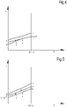
- Figs.4 and 5 show the same curves CO2, W and G, as already described in connection with Fig.3 , but in a partial load condition, i.e. when the amount of heat to be provided to the gas flowing in pipeline 7 is around 50% of the heat required in the operating condition shown in Fig. 3 (full load). This can be due for instance to a drop in the gas demand from the low-pressure gas distribution network 5 and a consequent reduction of the gas flow rate through the expander 11.
- the flow rate of the heat transfer fluid in the heat transfer circuit 19 is identical to the flow rate in Fig.3 .
- Fig.5 a situation is depicted, wherein the same amount of heat as in Fig. 4 is transferred by the transcritical heat pump 23 to the gas in pipeline 7 through the heat transfer circuit 19, but using a different flow rate of the heat transfer fluid circulating therein.
- the gas temperature at the inlet and outlet of the heat exchanger 9 are labeled T1' and T2', respectively.
- the inlet and outlet temperatures of the heat transfer fluid are labeled T3' and T4'.
- References T5' and T6' designate the temperatures of the working fluid of the transcritical heat pump 23 at the inlet and outlet of the heat exchanger 29, respectively.
- the operating condition of the transcritical heat pump 23 is controlled by the controller 23C such that the COP of the transcritical heat pump 23 is maximized under the conditions set by controller 51.
- the temperatures T5' and T6' and consequently the temperatures T3' and T4' are determined by the controller 23C, and are such that the gas temperature T2' ensures the gas outlet temperature T out remains around the temperature set point Ts.
- the angle of inclination of the line G is proportional to 1 mg ⁇ cpg wherein:
- Fig.4 shows that the heat exchanger 9 is in actual fact over-sized, as evidenced by the difference between temperature of the gas and the temperature of the heat transfer fluid becoming zero at a certain point; i.e. only a portion of the total heat exchanger surface is actually exploited.
- the same amount of heat (50% of Q) can be transferred from the heat transfer fluid to the gas flowing in pipeline 7 under a different operating condition of the heat transfer circuit 19, by changing the flow rate of the heat transfer fluid.
- Fig. 5 shows a situation where the same amount of heat as in Fig.4 is delivered to the gas flowing in pipeline 7, using a lower flow rate of the heat transfer fluid in the heat transfer circuit 19.
- the change in the flow rate of the heat transfer fluid corresponds to a variation of the inclination ⁇ of the curve W.
- the operating conditions of Figs. 4 and 5 both meet the request from the temperature control loop and pressure control loop featured by controller 51, and both correspond to an operating point of the transcritical heat pump 23 which maximizes the COP thereof.
- controller 51 controls the flow rate of the heat transfer fluid in the heat transfer circuit 19
- two different COP can be achieved, the one corresponding to a lower flow rate of the heat transfer fluid being higher, since the mean temperature of the working fluid in the working fluid circuit of the transcritical heat pump 23 along line AB is lower.
- the pressure control loop and the temperature control loop of controller 51 cause the operating point of system 1 to change in order to maintain the outlet temperature T out and the outlet pressure P out of the gas downstream of the expander 11 around the temperature set point Ts and the pressure set point Ps, respectively. More specifically, the pressure control loop modifies the gas flow rate through pipeline 7 and expander 11.
- the temperature control loop causes adjustment of the gas temperature T2 at the outlet of the heat exchanger 9. For a given flow rate of the heat transfer fluid in the heat transfer circuit 19, the gas temperature T2 can be achieved under a univocally determined operating condition of the transcritical heat pump 23, which provides the maximum COP, said univocally determined operating condition being set by the controller 23C of the transcritical heat pump 23.
- the flow rate of the heat transfer fluid in the heat transfer circuit 19 is a further variable of the system, which can be acted upon to further optimize the COP of the transcritical heat pump 23.
- a further control loop can thus be provided, which controls the flow rate of the heat transfer fluid in the heat transfer circuit 19, e.g. by changing the rotational speed of pump 21.
- This further control loop will be referred to herein as flowrate control loop.
- the flowrate control loop changes the flow rate of the heat transfer fluid in heat transfer circuit 19 to set the flow rate at an optimal value, which corresponds to an optimal maximum COP of the transcritical heat pump 23.
- the flowrate control circuit can provide a flowrate control signal Ef(see Fig.1 ), which is applied to pump 21, for changing the flow rate of the heat transfer fluid until optimal COP conditions are achieved.
- the above described flowrate control loop is particularly effective, since it is based on simple temperature measurements, which can be performed by temperature sensors, schematically shown in Fig. 1 at T1, T2, T3 and T4.
- the method does not require access to data from the transcritical heat pump 23 and does not require complex thermodynamic calculations. It also does not require any knowledge of information on the internal operation of the transcritical heat pump 23.
- the flowrate control loop can be configured also in a different manner.
- the COP of the transcritical heat pump 23 can be calculated for a given set of operating parameters.
- the flowrate control loop can for instance be based on an iterative perturb-and-observe algorithm and cause stepwise variations of the flow rate of the heat transfer fluid in the heat transfer circuit 19. If the flow rate variation causes a drop of the COP, this means that an opposite variation is required and will be applied at the next iterative step. For instance, if an increase of the flow rate of the heat transfer fluid causes a drop of the COP, the next iterative step will decrease the flow rate, until the maximum COP is achieved for a given working point of the expander 11.
- the expander 11 is dimensioned to support a gas flow rate which is only a fraction of the maximum flow rate, which can be delivered through the system 1. This takes into account the fact that a pressure-let-down system operates for most of the time under partial-load conditions. It would thus be ineffective to design the expander 11 and the transcritical heat pump 23 to support the maximum gas flow rate, which can be demanded by the low-pressure gas distribution network 5.
- One of the pressure control valves 39.1-39.n is partly opened and used for dynamically adapting the flow rate therethrough to meet the request from the low-pressure gas distribution network 5, maintaining the outlet gas pressure at the requested pressure set point Ps.
- the heater 41 is used to heat the gas flowing through the pressure control valve arrangement 39 such that the outlet gas temperature T out is maintained at the temperature set point Ts. Control of the pressure control valve arrangement 39 and of the heater 41 can be performed in a manner known per se by a controller separate from controller 51.
- the temperature T out is actually measured downstream of a point where the gas flowing through expander 11 mixes with the gas flowing through the pressure control valve arrangement 39, as shown in Fig.1 .
- What matters and shall be controlled is in fact the gas temperature at the outlet of the system 1, which depends upon the flow rates through the two gas flow paths 7 and 37.
- the gas can be heated downstream of the expander 11 rather than upstream thereof, by arranging the heat exchanger 9 downstream of the expander 11 with respect to the direction of the gas flow F. The same holds true for the heater arrangement 41 and the pressure control valve arrangement 39 along the delivery path 37.
Landscapes
- Engineering & Computer Science (AREA)
- Mechanical Engineering (AREA)
- General Engineering & Computer Science (AREA)
- Physics & Mathematics (AREA)
- Thermal Sciences (AREA)
- Chemical & Material Sciences (AREA)
- Combustion & Propulsion (AREA)
- Pipeline Systems (AREA)
- Engine Equipment That Uses Special Cycles (AREA)
- Mobile Radio Communication Systems (AREA)
Claims (15)
- Système (1) pour mettre hors pression un gaz dans une canalisation, le système comprenant :un détendeur (11) configuré et agencé pour générer une puissance mécanique en détendant un gaz d'une première pression à une seconde pression, la première pression étant supérieure à la seconde pression ;une pompe à chaleur (23) ; etun circuit de transfert de chaleur (19) contenant un fluide caloporteur circulant à l'intérieur de celui-ci, pour recevoir la chaleur de la pompe à chaleur (23) et distribuer la chaleur au gaz par le biais d'un échangeur de chaleur (9) ;caractérisé par un dispositif de commande (51), configuré et agencé pour moduler un débit du fluide caloporteur circulant dans le circuit de transfert de chaleur (19) en fonction d'un rendement thermique à transférer du fluide caloporteur vers le gaz, à savoir en fonction de différentiels de température entre le gaz et le fluide caloporteur au niveau d'un côté entrée de gaz et d'un côté sortie de gaz de l'échangeur de chaleur (9).
- Système selon la revendication 1, dans lequel l'échangeur de chaleur (9) est agencé en amont du détendeur (11) par rapport à une direction d'écoulement du gaz dans la canalisation.
- Système selon la revendication 1 ou 2, dans lequel la pompe à chaleur (23) est une pompe à chaleur transcritique.
- Système selon une ou plusieurs des revendications précédentes, dans lequel le dispositif de commande (51) est connecté de manière opérationnelle à des capteurs de température, agencés et configurés pour mesurer des températures de gaz au niveau de l'entrée et au niveau de la sortie de l'échangeur de chaleur (9) et pour mesurer en outre les températures du fluide caloporteur au niveau de l'entrée et au niveau de la sortie de l'échangeur de chaleur (9).
- Système selon une ou plusieurs des revendications précédentes, dans lequel le dispositif de commande (51) présente une boucle de régulation de débit configurée pour moduler le débit du fluide caloporteur de manière à minimiser une différence entre un premier différentiel de température entre le gaz et le fluide caloporteur au niveau de l'entrée de gaz de l'échangeur de chaleur (9), et un second différentiel de température entre le gaz et le fluide caloporteur au niveau de la sortie de gaz de l'échangeur de chaleur (9).
- Système selon la revendication 5 prise en dépendance de la revendication 3, dans lequel la boucle de régulation de débit est configurée pour changer le débit du fluide caloporteur dans le circuit de transfert de chaleur (19) de manière à maximiser le coefficient de performance (COP) de la pompe à chaleur transcritique (23).
- Système selon une ou plusieurs des revendications précédentes, dans lequel le dispositif de commande (51) présente une boucle de régulation de température agencée et configurée pour minimiser une différence entre une température de gaz en aval du détendeur (11) et un point de consigne de température de gaz, en agissant sur le rendement thermique du fluide caloporteur vers le gaz.
- Système selon une ou plusieurs des revendications précédentes, dans lequel le dispositif de commande (51) présente une boucle de régulation de pression agencée et configurée pour minimiser une différence entre une pression de gaz en aval du détendeur (11) et un point de consigne de pression de gaz, en agissant sur le débit de gaz à travers le détendeur (11).
- Système selon une ou plusieurs des revendications précédentes, dans lequel le détendeur (11) a des aubes de guidage d'entrée variables, et dans lequel le dispositif de commande (51) est configuré et agencé pour ajuster un débit de gaz à travers le détendeur (11) en agissant sur les aubes de guidage d'entrée variables.
- Système selon une ou plusieurs des revendications précédentes, comprenant en outre un conduit de distribution de gaz (37) agencé parallèlement au détendeur (11) et à l'échangeur de chaleur (9) ; dans lequel le long du conduit de distribution de gaz (37) un agencement de soupape de régulation de pression (39) et un élément chauffant (43) sont agencés, l'élément chauffant (43) étant de préférence situé en amont de l'agencement de soupape de commande de pression (39) par rapport à la direction d'écoulement de gaz dans le conduit de distribution de gaz (37) ; et dans lequel l'agencement de soupape de régulation de pression (39) comprend de préférence une pluralité de vannes de régulation de pression disposées en parallèle.
- Procédé pour mettre hors pression un gaz dans une canalisation, le procédé comprenant les étapes suivantes :la distribution d'un gaz par le biais d'un échangeur de chaleur (9) et d'un détendeur (11) ;le chauffage du gaz dans l'échangeur de chaleur (9) en distribuant à celui-ci la chaleur provenant d'une pompe à chaleur (23) par le biais d'un fluide caloporteur circulant dans un circuit de transfert de chaleur (19) et en relation d'échange de chaleur avec le gaz et avec un fluide de travail traité par la pompe à chaleur (23) ;la détente du gaz d'une première pression à une seconde pression dans le détendeur (11) et la génération d'une puissance mécanique avec celle-ci ;caractérisé par la modulation d'un débit du fluide caloporteur dans le circuit de transfert de chaleur (19) en fonction d'un rendement thermique à transférer du fluide caloporteur au gaz, à savoir en fonction de différentiels de température entre le gaz et le fluide caloporteur au niveau d'un côté entrée de gaz et d'un côté sortie de gaz de l'échangeur de chaleur (9).
- Procédé selon la revendication 11, dans lequel l'étape de chauffage du gaz dans l'échangeur de chaleur (9) est réalisée avant l'étape de détente du gaz dans le détendeur (11), l'échangeur de chaleur (9) étant agencé en amont du détendeur (11) par rapport à une direction d'écoulement de gaz.
- Procédé selon une ou plusieurs des revendications 11 à 12, comprenant l'étape consistant à moduler le débit du fluide caloporteur en fonction de différentiels de température entre le gaz et le fluide caloporteur au niveau d'un côté entrée de gaz et d'un côté sortie de gaz de l'échangeur de chaleur (9).
- Procédé selon une ou plusieurs des revendications 11 à 13, comprenant l'étape consistant à moduler le débit du fluide caloporteur de manière à minimiser une différence entre un premier différentiel de température entre un gaz et un fluide caloporteur au niveau de l'entrée de gaz de l'échangeur de chaleur (9), et un second différentiel de température entre le gaz et le fluide caloporteur au niveau de la sortie de gaz de l'échangeur de chaleur (9).
- Procédé selon une ou plusieurs des revendications 11 à 14, comprenant l'étape réduisant au minimum une différence entre une température de gaz en aval du détendeur (11) et un point de consigne de température de gaz, en agissant sur le rendement thermique du fluide caloporteur vers le gaz.
Applications Claiming Priority (2)
| Application Number | Priority Date | Filing Date | Title |
|---|---|---|---|
| ITUB2015A006071A ITUB20156071A1 (it) | 2015-12-02 | 2015-12-02 | Sistema e metodo di controllo per cabine remi |
| PCT/EP2016/079422 WO2017093396A1 (fr) | 2015-12-02 | 2016-12-01 | Système et procédé de commande pour stations de baisse de pression |
Publications (3)
| Publication Number | Publication Date |
|---|---|
| EP3384203A1 EP3384203A1 (fr) | 2018-10-10 |
| EP3384203B1 true EP3384203B1 (fr) | 2022-06-15 |
| EP3384203B8 EP3384203B8 (fr) | 2022-08-10 |
Family
ID=55447044
Family Applications (1)
| Application Number | Title | Priority Date | Filing Date |
|---|---|---|---|
| EP16815564.6A Active EP3384203B8 (fr) | 2015-12-02 | 2016-12-01 | Système et procédé de commande pour stations de baisse de pression |
Country Status (6)
| Country | Link |
|---|---|
| US (1) | US10677392B2 (fr) |
| EP (1) | EP3384203B8 (fr) |
| JP (1) | JP6909216B2 (fr) |
| IT (1) | ITUB20156071A1 (fr) |
| RU (1) | RU2731147C2 (fr) |
| WO (1) | WO2017093396A1 (fr) |
Families Citing this family (20)
| Publication number | Priority date | Publication date | Assignee | Title |
|---|---|---|---|---|
| US10443586B1 (en) | 2018-09-12 | 2019-10-15 | Douglas A Sahm | Fluid transfer and depressurization system |
| CN109636673A (zh) * | 2018-12-25 | 2019-04-16 | 烟台清泉实业有限公司 | 分户供暖计费阀控方法、装置及系统 |
| IT201900004675A1 (it) * | 2019-03-28 | 2020-09-28 | Me Te Ma Srl | Impianto e procedimento per la regolazione della pressione del gas metano proveniente dalla rete. |
| BE1027533B1 (nl) * | 2019-08-29 | 2021-03-30 | Atlas Copco Airpower Nv | Volumetrische expanderinrichting |
| CN110966518B (zh) * | 2019-12-25 | 2022-03-08 | 苏州焜原光电有限公司 | 气体充装系统及充装方法 |
| US11493029B2 (en) | 2021-04-02 | 2022-11-08 | Ice Thermal Harvesting, Llc | Systems and methods for generation of electrical power at a drilling rig |
| US11293414B1 (en) | 2021-04-02 | 2022-04-05 | Ice Thermal Harvesting, Llc | Systems and methods for generation of electrical power in an organic rankine cycle operation |
| US11644015B2 (en) | 2021-04-02 | 2023-05-09 | Ice Thermal Harvesting, Llc | Systems and methods for generation of electrical power at a drilling rig |
| US11359576B1 (en) | 2021-04-02 | 2022-06-14 | Ice Thermal Harvesting, Llc | Systems and methods utilizing gas temperature as a power source |
| US11421663B1 (en) | 2021-04-02 | 2022-08-23 | Ice Thermal Harvesting, Llc | Systems and methods for generation of electrical power in an organic Rankine cycle operation |
| WO2022213113A1 (fr) * | 2021-04-02 | 2022-10-06 | Ice Thermal Harvesting, Llc | Systèmes et procédés de production d'énergie électrique au niveau d'un appareil de forage |
| US11486370B2 (en) | 2021-04-02 | 2022-11-01 | Ice Thermal Harvesting, Llc | Modular mobile heat generation unit for generation of geothermal power in organic Rankine cycle operations |
| US11255315B1 (en) | 2021-04-02 | 2022-02-22 | Ice Thermal Harvesting, Llc | Controller for controlling generation of geothermal power in an organic Rankine cycle operation during hydrocarbon production |
| US12312981B2 (en) | 2021-04-02 | 2025-05-27 | Ice Thermal Harvesting, Llc | Systems and methods utilizing gas temperature as a power source |
| US11480074B1 (en) | 2021-04-02 | 2022-10-25 | Ice Thermal Harvesting, Llc | Systems and methods utilizing gas temperature as a power source |
| US11592009B2 (en) | 2021-04-02 | 2023-02-28 | Ice Thermal Harvesting, Llc | Systems and methods for generation of electrical power at a drilling rig |
| JP7788690B2 (ja) * | 2022-01-27 | 2025-12-19 | 東京瓦斯株式会社 | 流体流通システム |
| US12534990B2 (en) | 2022-12-29 | 2026-01-27 | Ice Thermal Harvesting, Llc | Power generation assemblies for hydraulic fracturing systems and methods |
| US12180861B1 (en) | 2022-12-30 | 2024-12-31 | Ice Thermal Harvesting, Llc | Systems and methods to utilize heat carriers in conversion of thermal energy |
| EP4411205A1 (fr) * | 2023-02-02 | 2024-08-07 | Enersem S.r.l. | Procédé de commande du fonctionnement d'une installation de chauffage hybride pour chauffer un gaz et installation de chauffage hybride associée |
Citations (3)
| Publication number | Priority date | Publication date | Assignee | Title |
|---|---|---|---|---|
| EP2264288B1 (fr) * | 2009-06-11 | 2011-08-03 | Thermonetics LTD. | Système pour une dépressurisation de fluides efficace |
| EP2390470B1 (fr) * | 2010-05-24 | 2013-03-27 | Nuovo Pignone S.p.A. | Procédé et système pour buses d'entrées à géométrie variable à utiliser dans des turboexpanseurs |
| EP1865249B1 (fr) * | 2006-06-07 | 2014-02-26 | 2Oc | Réducteur de pression de gaz et système de génération et de gestion d'énergie comprenant un réducteur de pression de gaz |
Family Cites Families (20)
| Publication number | Priority date | Publication date | Assignee | Title |
|---|---|---|---|---|
| US3877218A (en) * | 1971-09-14 | 1975-04-15 | William H Nebgen | Brayton cycle system with refrigerated intake and condensed water injection |
| US3820590A (en) * | 1973-02-28 | 1974-06-28 | B Littman | On-line adaptive control of a heat exchanger |
| US4061185A (en) * | 1975-05-16 | 1977-12-06 | Canada Square Management Ltd. | Temperature control system |
| US4265223A (en) * | 1978-09-18 | 1981-05-05 | The Badger Company, Inc. | Method and apparatus for utilizing solar energy |
| SU953387A1 (ru) * | 1980-09-26 | 1982-08-23 | Предприятие П/Я А-3605 | Способ автоматического управлени криогенной гелиевой системой |
| US5395451A (en) * | 1993-05-26 | 1995-03-07 | Schmidt-Bretten, Inc. | Paint temperature control system |
| JP3597552B2 (ja) * | 1994-01-31 | 2004-12-08 | 大阪瓦斯株式会社 | エネルギー回収装置付き都市ガス整圧装置 |
| JPH08121699A (ja) * | 1994-10-18 | 1996-05-17 | Osaka Gas Co Ltd | 高圧ガス整圧装置 |
| US5904292A (en) * | 1996-12-04 | 1999-05-18 | Mcintosh; Douglas S. | Modulating fluid control device |
| RU14603U1 (ru) | 2000-03-01 | 2000-08-10 | Московский энергетический институт (Технический университет) | Автономное устройство для тепло- и электроснабжения |
| GB2374949A (en) * | 2001-04-27 | 2002-10-30 | Ashe Morris Ltd | Monitoring and controlling reaction system in reactor |
| GB0121071D0 (en) * | 2001-08-31 | 2001-10-24 | Ashe Morris Ltd | Multi-port flow control valves |
| US6898082B2 (en) * | 2002-05-10 | 2005-05-24 | Serguei V. Dessiatoun | Enhanced heat transfer structure with heat transfer members of variable density |
| US7110906B2 (en) * | 2004-07-22 | 2006-09-19 | Abb Inc. | System and method for monitoring the performance of a heat exchanger |
| US8069677B2 (en) * | 2006-03-15 | 2011-12-06 | Woodside Energy Ltd. | Regasification of LNG using ambient air and supplemental heat |
| JP5018496B2 (ja) * | 2008-01-16 | 2012-09-05 | ダイキン工業株式会社 | 冷凍装置 |
| JP5383338B2 (ja) * | 2009-06-17 | 2014-01-08 | 三菱重工業株式会社 | Co2回収装置及びco2回収方法 |
| HK1217527A1 (zh) * | 2013-07-19 | 2017-01-13 | Itm动力(研究)有限公司 | 减压系统 |
| US10018079B2 (en) * | 2015-01-23 | 2018-07-10 | Ford Global Technologies, Llc | Thermodynamic system in a vehicle |
| US20170219219A1 (en) * | 2016-02-01 | 2017-08-03 | Keith A. Miller | Demand based hvac (heating, ventilation, air conditioning) control |
-
2015
- 2015-12-02 IT ITUB2015A006071A patent/ITUB20156071A1/it unknown
-
2016
- 2016-12-01 JP JP2018528016A patent/JP6909216B2/ja active Active
- 2016-12-01 RU RU2018119231A patent/RU2731147C2/ru active
- 2016-12-01 EP EP16815564.6A patent/EP3384203B8/fr active Active
- 2016-12-01 US US15/780,731 patent/US10677392B2/en active Active
- 2016-12-01 WO PCT/EP2016/079422 patent/WO2017093396A1/fr not_active Ceased
Patent Citations (4)
| Publication number | Priority date | Publication date | Assignee | Title |
|---|---|---|---|---|
| EP1865249B1 (fr) * | 2006-06-07 | 2014-02-26 | 2Oc | Réducteur de pression de gaz et système de génération et de gestion d'énergie comprenant un réducteur de pression de gaz |
| EP2264288B1 (fr) * | 2009-06-11 | 2011-08-03 | Thermonetics LTD. | Système pour une dépressurisation de fluides efficace |
| US8028535B2 (en) * | 2009-06-11 | 2011-10-04 | Thermonetics Ltd. | System for efficient fluid depressurisation |
| EP2390470B1 (fr) * | 2010-05-24 | 2013-03-27 | Nuovo Pignone S.p.A. | Procédé et système pour buses d'entrées à géométrie variable à utiliser dans des turboexpanseurs |
Also Published As
| Publication number | Publication date |
|---|---|
| RU2018119231A (ru) | 2020-01-09 |
| EP3384203A1 (fr) | 2018-10-10 |
| JP2018537629A (ja) | 2018-12-20 |
| ITUB20156071A1 (it) | 2017-06-02 |
| RU2731147C2 (ru) | 2020-08-31 |
| WO2017093396A1 (fr) | 2017-06-08 |
| RU2018119231A3 (fr) | 2020-03-02 |
| US20180356044A1 (en) | 2018-12-13 |
| EP3384203B8 (fr) | 2022-08-10 |
| JP6909216B2 (ja) | 2021-07-28 |
| US10677392B2 (en) | 2020-06-09 |
Similar Documents
| Publication | Publication Date | Title |
|---|---|---|
| EP3384203B1 (fr) | Système et procédé de commande pour stations de baisse de pression | |
| Banasiak et al. | Development and performance mapping of a multi-ejector expansion work recovery pack for R744 vapour compression units | |
| Bian et al. | A comprehensive evaluation of the effect of different control valves on the dynamic performance of a recompression supercritical CO2 Brayton cycle | |
| US9896974B2 (en) | Multiple organic rankine cycle systems and methods | |
| Śmierciew et al. | Experimental investigation of the first prototype ejector refrigeration system with HFO-1234ze (E) | |
| MX2011013360A (es) | Sistema para la despresurizacion eficiente de fluido. | |
| JP6913044B2 (ja) | 圧縮空気貯蔵発電装置 | |
| CN101368767A (zh) | 采用并联正、逆制冷循环的工质的间接空气冷却方法和系统 | |
| CN101988431A (zh) | 用于向燃气轮机供应燃料的系统及方法 | |
| Jiang et al. | Thermodynamic performance analysis, assessment and comparison of an advanced trigenerative compressed air energy storage system under different operation strategies | |
| Wang et al. | Dynamic simulation study of the start-up and shutdown processes for a recompression CO2 Brayton cycle | |
| Gagan et al. | Investigations of thermal performance of ejection refrigeration system driven by low grade heat | |
| Cui et al. | Experimental study on the performance and control strategy of a water-cooled subcooler-assisted carbon dioxide heat pump for combined cooling and heating | |
| US6851265B2 (en) | Steam cooling control for a combined cycle power plant | |
| RU106307U1 (ru) | Станция регулирования давления системы распределения природного газа (варианты) | |
| CN105888845A (zh) | 一种天然气差压冷能利用装置 | |
| KR102242144B1 (ko) | 가스 터빈 흡기 시스템을 갖는 발전소 | |
| US9145794B2 (en) | Apparatus and method for increasing power plant efficiency at partial loads | |
| US20030070432A1 (en) | Natural gas depressurization temperature maintenance expansion system with production of useful work | |
| KR20170134127A (ko) | 복수의 팽창기를 구비한 열병합 발전시스템 | |
| JP3625583B2 (ja) | 高圧ガスからの圧力エネルギー回収設備 | |
| WO2015124909A1 (fr) | Système d'alimentation en carburant amélioré pour une turbine à gaz | |
| Marchionni et al. | Dynamics of SCO2 heat to power units equipped with dual tank inventory control system | |
| Feng et al. | Variable load operation characteristics of CO2 closed cycle system for unmanned underwater vehicle | |
| KR20180017752A (ko) | 복수의 팽창기를 구비한 열병합 발전시스템 |
Legal Events
| Date | Code | Title | Description |
|---|---|---|---|
| STAA | Information on the status of an ep patent application or granted ep patent |
Free format text: STATUS: UNKNOWN |
|
| STAA | Information on the status of an ep patent application or granted ep patent |
Free format text: STATUS: THE INTERNATIONAL PUBLICATION HAS BEEN MADE |
|
| PUAI | Public reference made under article 153(3) epc to a published international application that has entered the european phase |
Free format text: ORIGINAL CODE: 0009012 |
|
| STAA | Information on the status of an ep patent application or granted ep patent |
Free format text: STATUS: REQUEST FOR EXAMINATION WAS MADE |
|
| 17P | Request for examination filed |
Effective date: 20180702 |
|
| AK | Designated contracting states |
Kind code of ref document: A1 Designated state(s): AL AT BE BG CH CY CZ DE DK EE ES FI FR GB GR HR HU IE IS IT LI LT LU LV MC MK MT NL NO PL PT RO RS SE SI SK SM TR |
|
| AX | Request for extension of the european patent |
Extension state: BA ME |
|
| DAV | Request for validation of the european patent (deleted) | ||
| DAX | Request for extension of the european patent (deleted) | ||
| STAA | Information on the status of an ep patent application or granted ep patent |
Free format text: STATUS: EXAMINATION IS IN PROGRESS |
|
| 17Q | First examination report despatched |
Effective date: 20201207 |
|
| GRAP | Despatch of communication of intention to grant a patent |
Free format text: ORIGINAL CODE: EPIDOSNIGR1 |
|
| STAA | Information on the status of an ep patent application or granted ep patent |
Free format text: STATUS: GRANT OF PATENT IS INTENDED |
|
| INTG | Intention to grant announced |
Effective date: 20220118 |
|
| GRAS | Grant fee paid |
Free format text: ORIGINAL CODE: EPIDOSNIGR3 |
|
| GRAA | (expected) grant |
Free format text: ORIGINAL CODE: 0009210 |
|
| STAA | Information on the status of an ep patent application or granted ep patent |
Free format text: STATUS: THE PATENT HAS BEEN GRANTED |
|
| AK | Designated contracting states |
Kind code of ref document: B1 Designated state(s): AL AT BE BG CH CY CZ DE DK EE ES FI FR GB GR HR HU IE IS IT LI LT LU LV MC MK MT NL NO PL PT RO RS SE SI SK SM TR |
|
| RAP3 | Party data changed (applicant data changed or rights of an application transferred) |
Owner name: NUOVO PIGNONE TECNOLOGIE S.R.L. |
|
| REG | Reference to a national code |
Ref country code: CH Ref legal event code: EP Ref country code: GB Ref legal event code: FG4D |
|
| GRAT | Correction requested after decision to grant or after decision to maintain patent in amended form |
Free format text: ORIGINAL CODE: EPIDOSNCDEC |
|
| REG | Reference to a national code |
Ref country code: IE Ref legal event code: FG4D |
|
| REG | Reference to a national code |
Ref country code: DE Ref legal event code: R096 Ref document number: 602016072881 Country of ref document: DE |
|
| REG | Reference to a national code |
Ref country code: AT Ref legal event code: REF Ref document number: 1498591 Country of ref document: AT Kind code of ref document: T Effective date: 20220715 Ref country code: CH Ref legal event code: PK Free format text: BERICHTIGUNG B8 |
|
| REG | Reference to a national code |
Ref country code: LT Ref legal event code: MG9D |
|
| REG | Reference to a national code |
Ref country code: NL Ref legal event code: MP Effective date: 20220615 |
|
| PG25 | Lapsed in a contracting state [announced via postgrant information from national office to epo] |
Ref country code: SE Free format text: LAPSE BECAUSE OF FAILURE TO SUBMIT A TRANSLATION OF THE DESCRIPTION OR TO PAY THE FEE WITHIN THE PRESCRIBED TIME-LIMIT Effective date: 20220615 Ref country code: NO Free format text: LAPSE BECAUSE OF FAILURE TO SUBMIT A TRANSLATION OF THE DESCRIPTION OR TO PAY THE FEE WITHIN THE PRESCRIBED TIME-LIMIT Effective date: 20220915 Ref country code: LT Free format text: LAPSE BECAUSE OF FAILURE TO SUBMIT A TRANSLATION OF THE DESCRIPTION OR TO PAY THE FEE WITHIN THE PRESCRIBED TIME-LIMIT Effective date: 20220615 Ref country code: HR Free format text: LAPSE BECAUSE OF FAILURE TO SUBMIT A TRANSLATION OF THE DESCRIPTION OR TO PAY THE FEE WITHIN THE PRESCRIBED TIME-LIMIT Effective date: 20220615 Ref country code: GR Free format text: LAPSE BECAUSE OF FAILURE TO SUBMIT A TRANSLATION OF THE DESCRIPTION OR TO PAY THE FEE WITHIN THE PRESCRIBED TIME-LIMIT Effective date: 20220916 Ref country code: FI Free format text: LAPSE BECAUSE OF FAILURE TO SUBMIT A TRANSLATION OF THE DESCRIPTION OR TO PAY THE FEE WITHIN THE PRESCRIBED TIME-LIMIT Effective date: 20220615 Ref country code: BG Free format text: LAPSE BECAUSE OF FAILURE TO SUBMIT A TRANSLATION OF THE DESCRIPTION OR TO PAY THE FEE WITHIN THE PRESCRIBED TIME-LIMIT Effective date: 20220915 |
|
| REG | Reference to a national code |
Ref country code: AT Ref legal event code: MK05 Ref document number: 1498591 Country of ref document: AT Kind code of ref document: T Effective date: 20220615 |
|
| PG25 | Lapsed in a contracting state [announced via postgrant information from national office to epo] |
Ref country code: RS Free format text: LAPSE BECAUSE OF FAILURE TO SUBMIT A TRANSLATION OF THE DESCRIPTION OR TO PAY THE FEE WITHIN THE PRESCRIBED TIME-LIMIT Effective date: 20220615 Ref country code: LV Free format text: LAPSE BECAUSE OF FAILURE TO SUBMIT A TRANSLATION OF THE DESCRIPTION OR TO PAY THE FEE WITHIN THE PRESCRIBED TIME-LIMIT Effective date: 20220615 |
|
| PG25 | Lapsed in a contracting state [announced via postgrant information from national office to epo] |
Ref country code: NL Free format text: LAPSE BECAUSE OF FAILURE TO SUBMIT A TRANSLATION OF THE DESCRIPTION OR TO PAY THE FEE WITHIN THE PRESCRIBED TIME-LIMIT Effective date: 20220615 |
|
| PG25 | Lapsed in a contracting state [announced via postgrant information from national office to epo] |
Ref country code: SM Free format text: LAPSE BECAUSE OF FAILURE TO SUBMIT A TRANSLATION OF THE DESCRIPTION OR TO PAY THE FEE WITHIN THE PRESCRIBED TIME-LIMIT Effective date: 20220615 Ref country code: SK Free format text: LAPSE BECAUSE OF FAILURE TO SUBMIT A TRANSLATION OF THE DESCRIPTION OR TO PAY THE FEE WITHIN THE PRESCRIBED TIME-LIMIT Effective date: 20220615 Ref country code: RO Free format text: LAPSE BECAUSE OF FAILURE TO SUBMIT A TRANSLATION OF THE DESCRIPTION OR TO PAY THE FEE WITHIN THE PRESCRIBED TIME-LIMIT Effective date: 20220615 Ref country code: PT Free format text: LAPSE BECAUSE OF FAILURE TO SUBMIT A TRANSLATION OF THE DESCRIPTION OR TO PAY THE FEE WITHIN THE PRESCRIBED TIME-LIMIT Effective date: 20221017 Ref country code: ES Free format text: LAPSE BECAUSE OF FAILURE TO SUBMIT A TRANSLATION OF THE DESCRIPTION OR TO PAY THE FEE WITHIN THE PRESCRIBED TIME-LIMIT Effective date: 20220615 Ref country code: EE Free format text: LAPSE BECAUSE OF FAILURE TO SUBMIT A TRANSLATION OF THE DESCRIPTION OR TO PAY THE FEE WITHIN THE PRESCRIBED TIME-LIMIT Effective date: 20220615 Ref country code: CZ Free format text: LAPSE BECAUSE OF FAILURE TO SUBMIT A TRANSLATION OF THE DESCRIPTION OR TO PAY THE FEE WITHIN THE PRESCRIBED TIME-LIMIT Effective date: 20220615 Ref country code: AT Free format text: LAPSE BECAUSE OF FAILURE TO SUBMIT A TRANSLATION OF THE DESCRIPTION OR TO PAY THE FEE WITHIN THE PRESCRIBED TIME-LIMIT Effective date: 20220615 |
|
| PG25 | Lapsed in a contracting state [announced via postgrant information from national office to epo] |
Ref country code: PL Free format text: LAPSE BECAUSE OF FAILURE TO SUBMIT A TRANSLATION OF THE DESCRIPTION OR TO PAY THE FEE WITHIN THE PRESCRIBED TIME-LIMIT Effective date: 20220615 Ref country code: IS Free format text: LAPSE BECAUSE OF FAILURE TO SUBMIT A TRANSLATION OF THE DESCRIPTION OR TO PAY THE FEE WITHIN THE PRESCRIBED TIME-LIMIT Effective date: 20221015 |
|
| REG | Reference to a national code |
Ref country code: DE Ref legal event code: R097 Ref document number: 602016072881 Country of ref document: DE |
|
| PG25 | Lapsed in a contracting state [announced via postgrant information from national office to epo] |
Ref country code: AL Free format text: LAPSE BECAUSE OF FAILURE TO SUBMIT A TRANSLATION OF THE DESCRIPTION OR TO PAY THE FEE WITHIN THE PRESCRIBED TIME-LIMIT Effective date: 20220615 |
|
| PLBE | No opposition filed within time limit |
Free format text: ORIGINAL CODE: 0009261 |
|
| STAA | Information on the status of an ep patent application or granted ep patent |
Free format text: STATUS: NO OPPOSITION FILED WITHIN TIME LIMIT |
|
| PG25 | Lapsed in a contracting state [announced via postgrant information from national office to epo] |
Ref country code: DK Free format text: LAPSE BECAUSE OF FAILURE TO SUBMIT A TRANSLATION OF THE DESCRIPTION OR TO PAY THE FEE WITHIN THE PRESCRIBED TIME-LIMIT Effective date: 20220615 |
|
| 26N | No opposition filed |
Effective date: 20230316 |
|
| PG25 | Lapsed in a contracting state [announced via postgrant information from national office to epo] |
Ref country code: SI Free format text: LAPSE BECAUSE OF FAILURE TO SUBMIT A TRANSLATION OF THE DESCRIPTION OR TO PAY THE FEE WITHIN THE PRESCRIBED TIME-LIMIT Effective date: 20220615 |
|
| P01 | Opt-out of the competence of the unified patent court (upc) registered |
Effective date: 20230526 |
|
| GBPC | Gb: european patent ceased through non-payment of renewal fee |
Effective date: 20221201 |
|
| REG | Reference to a national code |
Ref country code: BE Ref legal event code: MM Effective date: 20221231 |
|
| PG25 | Lapsed in a contracting state [announced via postgrant information from national office to epo] |
Ref country code: LU Free format text: LAPSE BECAUSE OF NON-PAYMENT OF DUE FEES Effective date: 20221201 |
|
| PG25 | Lapsed in a contracting state [announced via postgrant information from national office to epo] |
Ref country code: IE Free format text: LAPSE BECAUSE OF NON-PAYMENT OF DUE FEES Effective date: 20221201 Ref country code: GB Free format text: LAPSE BECAUSE OF NON-PAYMENT OF DUE FEES Effective date: 20221201 |
|
| PG25 | Lapsed in a contracting state [announced via postgrant information from national office to epo] |
Ref country code: BE Free format text: LAPSE BECAUSE OF NON-PAYMENT OF DUE FEES Effective date: 20221231 |
|
| PG25 | Lapsed in a contracting state [announced via postgrant information from national office to epo] |
Ref country code: IT Free format text: LAPSE BECAUSE OF FAILURE TO SUBMIT A TRANSLATION OF THE DESCRIPTION OR TO PAY THE FEE WITHIN THE PRESCRIBED TIME-LIMIT Effective date: 20220615 |
|
| PG25 | Lapsed in a contracting state [announced via postgrant information from national office to epo] |
Ref country code: HU Free format text: LAPSE BECAUSE OF FAILURE TO SUBMIT A TRANSLATION OF THE DESCRIPTION OR TO PAY THE FEE WITHIN THE PRESCRIBED TIME-LIMIT; INVALID AB INITIO Effective date: 20161201 |
|
| PG25 | Lapsed in a contracting state [announced via postgrant information from national office to epo] |
Ref country code: CY Free format text: LAPSE BECAUSE OF FAILURE TO SUBMIT A TRANSLATION OF THE DESCRIPTION OR TO PAY THE FEE WITHIN THE PRESCRIBED TIME-LIMIT Effective date: 20220615 |
|
| PG25 | Lapsed in a contracting state [announced via postgrant information from national office to epo] |
Ref country code: MK Free format text: LAPSE BECAUSE OF FAILURE TO SUBMIT A TRANSLATION OF THE DESCRIPTION OR TO PAY THE FEE WITHIN THE PRESCRIBED TIME-LIMIT Effective date: 20220615 |
|
| PG25 | Lapsed in a contracting state [announced via postgrant information from national office to epo] |
Ref country code: MC Free format text: LAPSE BECAUSE OF FAILURE TO SUBMIT A TRANSLATION OF THE DESCRIPTION OR TO PAY THE FEE WITHIN THE PRESCRIBED TIME-LIMIT Effective date: 20220615 |
|
| PG25 | Lapsed in a contracting state [announced via postgrant information from national office to epo] |
Ref country code: MC Free format text: LAPSE BECAUSE OF FAILURE TO SUBMIT A TRANSLATION OF THE DESCRIPTION OR TO PAY THE FEE WITHIN THE PRESCRIBED TIME-LIMIT Effective date: 20220615 |
|
| PG25 | Lapsed in a contracting state [announced via postgrant information from national office to epo] |
Ref country code: MT Free format text: LAPSE BECAUSE OF FAILURE TO SUBMIT A TRANSLATION OF THE DESCRIPTION OR TO PAY THE FEE WITHIN THE PRESCRIBED TIME-LIMIT Effective date: 20220615 |
|
| PG25 | Lapsed in a contracting state [announced via postgrant information from national office to epo] |
Ref country code: BG Free format text: LAPSE BECAUSE OF FAILURE TO SUBMIT A TRANSLATION OF THE DESCRIPTION OR TO PAY THE FEE WITHIN THE PRESCRIBED TIME-LIMIT Effective date: 20220615 |
|
| PG25 | Lapsed in a contracting state [announced via postgrant information from national office to epo] |
Ref country code: BG Free format text: LAPSE BECAUSE OF FAILURE TO SUBMIT A TRANSLATION OF THE DESCRIPTION OR TO PAY THE FEE WITHIN THE PRESCRIBED TIME-LIMIT Effective date: 20220615 |
|
| PGFP | Annual fee paid to national office [announced via postgrant information from national office to epo] |
Ref country code: CH Payment date: 20250101 Year of fee payment: 9 |
|
| PG25 | Lapsed in a contracting state [announced via postgrant information from national office to epo] |
Ref country code: TR Free format text: LAPSE BECAUSE OF FAILURE TO SUBMIT A TRANSLATION OF THE DESCRIPTION OR TO PAY THE FEE WITHIN THE PRESCRIBED TIME-LIMIT Effective date: 20220615 |
|
| REG | Reference to a national code |
Ref country code: CH Ref legal event code: U11 Free format text: ST27 STATUS EVENT CODE: U-0-0-U10-U11 (AS PROVIDED BY THE NATIONAL OFFICE) Effective date: 20260101 |
|
| PGFP | Annual fee paid to national office [announced via postgrant information from national office to epo] |
Ref country code: DE Payment date: 20251126 Year of fee payment: 10 |
|
| PGFP | Annual fee paid to national office [announced via postgrant information from national office to epo] |
Ref country code: FR Payment date: 20251120 Year of fee payment: 10 |