EP3384238B1 - Procede de controle d'un laser rotatif afin de detecter une erreur de cone - Google Patents
Procede de controle d'un laser rotatif afin de detecter une erreur de cone Download PDFInfo
- Publication number
- EP3384238B1 EP3384238B1 EP16800937.1A EP16800937A EP3384238B1 EP 3384238 B1 EP3384238 B1 EP 3384238B1 EP 16800937 A EP16800937 A EP 16800937A EP 3384238 B1 EP3384238 B1 EP 3384238B1
- Authority
- EP
- European Patent Office
- Prior art keywords
- laser
- measuring
- distance
- detection field
- rotating
- Prior art date
- Legal status (The legal status is an assumption and is not a legal conclusion. Google has not performed a legal analysis and makes no representation as to the accuracy of the status listed.)
- Active
Links
Images


Classifications
-
- G—PHYSICS
- G01—MEASURING; TESTING
- G01C—MEASURING DISTANCES, LEVELS OR BEARINGS; SURVEYING; NAVIGATION; GYROSCOPIC INSTRUMENTS; PHOTOGRAMMETRY OR VIDEOGRAMMETRY
- G01C25/00—Manufacturing, calibrating, cleaning, or repairing instruments or devices referred to in the other groups of this subclass
-
- G—PHYSICS
- G01—MEASURING; TESTING
- G01C—MEASURING DISTANCES, LEVELS OR BEARINGS; SURVEYING; NAVIGATION; GYROSCOPIC INSTRUMENTS; PHOTOGRAMMETRY OR VIDEOGRAMMETRY
- G01C15/00—Surveying instruments or accessories not provided for in groups G01C1/00 - G01C13/00
- G01C15/002—Active optical surveying means
- G01C15/004—Reference lines, planes or sectors
Definitions
- the present invention relates to a method for checking a rotary laser for cone errors according to the preamble of claim 1.
- Rotation lasers are used indoors and outdoors for leveling and marking work, such as the display of horizontal, vertical or oblique laser markings on a target surface or the determination and checking of horizontal height profiles, vertical lines, alignment lines and plumb points.
- Rotation lasers can be arranged in different device positions, which are designed as horizontal and vertical positions. A distinction is made between horizontally usable rotating lasers, which are used only in the horizontal position, and horizontally and vertically usable rotating lasers, which are used in the horizontal position and vertical position.
- Rotation lasers that can be used horizontally have a first horizontal axis and a second horizontal axis as device axes, which run perpendicular to one another and span a horizontal plane.
- Rotation lasers that can be used horizontally and vertically have, as the device axis, a vertical axis in addition to the first and second horizontal axes, which runs perpendicular to the horizontal plane of the first and second horizontal axes.
- the accuracy In order to ensure the accuracy of a rotating laser in operation, the accuracy must be checked regularly and if the maximum difference defined by the device manufacturer has been exceeded, the rotating laser must be calibrated. The accuracy of the rotating laser is checked separately for each device axis. Methods for checking and / or calibrating a horizontal axis and methods for checking and / or calibrating a vertical axis are known.
- rotation lasers which can be used horizontally
- the first and second horizontal axes are checked in succession, the order being arbitrary.
- the vertical axis is checked after the first and second horizontal axes have been checked.
- the device axes are aligned in a defined state by means of a leveling device of the rotating laser.
- the defined state of the rotating laser in the horizontal position is referred to as the horizontal state and in the vertical position as the vertical state.
- the leveling device comprises a first leveling unit that aligns the first horizontal axis in a first defined state, a second leveling unit that aligns the second horizontal axis in a second defined state, and in the case of a rotating laser that can be used vertically, a third leveling unit that defines the vertical axis in a third Condition aligns.
- the leveling units each include an inclination sensor, which measures the inclination of the device axis, and an adjusting element, with which the inclination of the device axis can be adjusted. Ideally, the inclination sensors are aligned parallel to the assigned device axes. If a tilt sensor is not aligned parallel to the assigned device axis, the device axis has a tilt error.
- the sequence of the known methods for checking the TRIAX UL-300 and RL-100 1S rotating lasers for cone errors is identical; the procedures differ in the distance between the first and second measuring surfaces and in the measuring distances that the rotating lasers use in the first and second position have second measuring surface.
- the first and second measuring surfaces are at a distance of approx. 30 m for the TRIAX UL-300 rotating laser and approx. 50 m for the RL-100 1S rotating laser.
- the rotating laser TRIAX UL-300 has a first measuring distance of approx. 29 m in the first position and a second measuring distance of approx. 1 m to the second measuring surface in the second position.
- the rotating laser RL-100 1S has a first measuring distance in the first position of approx. 25 m and in the second position a second measuring distance of approx. 1 to 2 m to the second measuring surface.
- the rotating laser is set up in a horizontal position in the first position with a first measuring distance to the second measuring surface.
- the horizontal axes of the rotating laser are aligned in the first position in a horizontal state, the horizontal state of the first horizontal axis being determined by a first zero position and the horizontal state of the second horizontal axis being determined by a second zero position.
- the impact position of the rotating laser beam is marked as the first control point on the first measuring surface.
- the rotating laser is rotated by 180 ° around the axis of rotation of the rotating laser and the position of incidence of the rotating laser beam on the second measuring surface is marked as the second control point.
- the rotating laser is then set up in the horizontal position in the second position with a second measurement distance from the second measurement surface, the orientation of the horizontal axes being unchanged from the first position.
- the horizontal axes of the rotating laser are aligned in the horizontal position in the second position.
- the impact position of the rotating laser beam on the second measuring surface is marked as the third control point.
- the rotating laser is rotated by 180 ° around the axis of rotation of the rotating laser and the position of incidence of the rotating laser beam on the first measuring surface is marked as the fourth control point.
- the distance between the first and fourth control points on the first measurement surface is determined as the first difference and the distance between the second and third control points on the second measurement surface is determined as the second difference.
- the first and second differences are compared with a maximum difference specified by the device manufacturer. If the first and / or second difference exceeds the maximum difference, the rotating laser does not meet the accuracy requirements and should be adjusted by the device manufacturer.
- the maximum difference is 6 mm for the Sokkia TRIAX UL-300 rotating laser and 10 mm for the Topcon RL-100 1S rotating laser.
- the known methods for checking a rotary laser for cone errors have the disadvantage that the distances between the first measuring surface and the second measuring surface are fixed.
- the distance of 30 m specified for the Sokkia TRIAX UL-300 rotating laser and especially the distance of 50 m specified for the Topcon RL-100 1S rotating laser between the first and second measuring surface is often not available for indoor measuring tasks.
- the impact positions of the laser beam will be transferred manually by the operator to the measuring surfaces, which is unsuitable for automating the method.
- Another disadvantage is that the accuracy of the method depends on the care of the operator when determining the center point of the laser beam, when transferring the center point to the measuring surface and when determining the distance between the control points.
- the object of the present invention is to develop a method for checking a rotary laser for cone errors, which can be adapted to the ambient conditions of the measurement environment.
- the method should be suitable for a largely automatic execution.
- the measuring distances D 1 , D 2 between the rotating laser and the laser receiver are measured in the first and second position and are not fixed to predetermined measuring distances.
- the incident positions of the laser beam on the second measuring surface are determined in the method according to the invention with a laser receiver and stored as a height offset H 1 , H 2 to the zero position of the detection field.
- the use of a laser receiver with a measuring function increases the measuring accuracy when carrying out the method.
- the laser receiver determines the impact position of the laser beam on the detection field according to a fixed routine.
- the method according to the invention can be carried out automatically in the first and second position; the operator only has to move the rotating laser from the first position to the second position.
- the rotating laser is aligned in the first position in any measurement direction on the second measurement surface.
- the first horizontal axis, the second horizontal axis or any axis in the horizontal plane can be aligned with the second measuring surface. It is important that the orientation of the rotary laser in the second location position is unchanged from the first location position and that the defined measurement direction is aligned with the second measurement surface.
- the first control point on the first measuring surface is used to adjust the height of the rotating laser in the second position.
- the cone error ⁇ becomes the first measuring distance D 1 , the second measuring distance D 2 and the difference ⁇ between the first and second height offset H 1 , H 2 are calculated.
- the incident position of the laser beam on the first measuring surface in the first position is determined by a further laser receiver.
- the use of a further laser receiver has the advantage that the impact position of the laser beam on the first measuring surface can be determined with a high degree of measuring accuracy.
- the position of the first measuring surface and the distance to the second measuring surface can be adapted to the respective measuring environment. If the rotating laser and the laser receiver have an auto-alignment function, the method steps of the method according to the invention can be carried out fully automatically in the first and second position. The operator only has to move the rotating laser from the first position to the second position.
- the height setting of the rotary laser in the second local position is particularly preferably regulated. Since the first and second measuring distances D 1 , D 2 are arbitrary, the height of the rotating laser must be set so that deviations are due to cone errors.
- the first control point of the laser beam on the first measuring surface is used for this.
- the height of the rotating laser is adjusted in the second position so that the position of the laser beam on the first measuring surface coincides with the first control point. If the height adjustment is controlled, the process can be carried out automatically.
- the first control point is saved by the other laser receiver and used with the help of an auto-alignment function to adjust the height of the rotating laser.
- the auto-alignment function is in the European patent EP 1 203 930 B1 described.
- the first measuring distance in the first location position and / or the second measuring distance in the second location position are preferably determined by means of the rotating laser and the laser receiver.
- the method according to the invention has the advantage that the environmental conditions of the measurement environment can be taken into account when checking the rotary laser for cone errors.
- the first and second measuring distances between the rotating laser and the laser receiver in the first and second position can be selected as the measuring environment allows.
- the first and / or second measuring distance between the rotating laser and the laser receiver are particularly preferably determined as the first distance by means of a first measuring method, as the second distance by means of a second measuring method or as the mean distance from the first and second distances. If the first and / or second measuring distance between the rotating laser and the laser receiver can be determined using different measuring methods, the method for checking the rotating laser for cone errors can be adapted to the ambient conditions of the measuring environment and the functions of the measuring devices (rotating laser and laser receiver).
- the first and / or second measuring distance between the rotating laser and the laser receiver is determined as the first distance by means of the first measuring method.
- the laser beam is inclined by a known angle of inclination and the distance of the inclined laser beam from the zero position of the detection field is stored.
- the first measurement method is suitable for laser receivers with a measurement function that can measure the distance of a laser beam to a zero position.
- the laser beam can be inclined by the inclination angle using the leveling device of the rotating laser.
- the leveling device comprises a first leveling unit that aligns the first horizontal axis in a first defined state, a second leveling unit that aligns the second horizontal axis in a second defined state.
- the rotating laser can be oriented in any measurement direction on the second measurement surface, wherein the first horizontal axis, the second horizontal axis or any axis in the horizontal plane can be defined as the measurement direction. If the first or second horizontal axis is used as the measuring direction, the rotating laser for the distance measurement is arranged in a suitable angular position.
- the laser beam is inclined by means of the first leveling unit if the first horizontal axis is used as the measuring direction and by means of the second leveling unit if the second horizontal axis is used as the measuring direction.
- tan ( ⁇ ) ⁇ sin ( ⁇ ) applies approximately.
- the first variant of the first measuring method is particularly suitable for rotating lasers and laser receivers with an auto-alignment function, in which the height adjustment of the laser beam to the zero position of the detection field of the laser receiver can be carried out automatically.
- tan ( ⁇ ) ⁇ sin ( ⁇ ) applies approximately.
- the second variant of the first measuring method is suitable for rotating lasers and laser receivers without an auto-alignment function. The operator only has to ensure that the laser beam inclined by the angle of inclination ⁇ is detected by the detection field of the laser receiver. In the case of a rotating laser and laser receiver with an auto-alignment function, the laser beam is automatically moved into the area of the detection field.
- tan (2 ⁇ ) ⁇ sin (2 ⁇ ) applies.
- the third variant of the first measuring method is suitable for rotating lasers and laser receivers with and without an auto-alignment function. If the horizontally aligned laser beam is initially aligned with the zero position of the detection field or at least in the vicinity of the zero position, the entire detection height of the detection field can be used. In the case of a device system with an auto-alignment function, the height adjustment to the zero position can be carried out automatically.
- the first and / or second measuring distance between the rotating laser and the laser receiver is determined as a second distance by means of the second measuring method.
- the rotating laser becomes horizontal aligned
- the horizontally aligned laser beam is rotated at a rotation speed v R around the axis of rotation
- the signal length t s of the rotating laser beam on the detection field of the laser receiver is determined and the second distance d 2 is determined from the rotation speed v R
- the signal length t s and Detection width B D of the detection field is calculated.
- the rotational speed v R is given in revolutions per minute and the time t full required for one revolution is 60 / v R.
- the second measuring method is suitable for rotating lasers and laser receivers without an auto-alignment function.
- the laser receiver must be able to measure the signal length t s of the rotating laser beam on the detection field.
- the first and / or second measurement distance between the rotating laser and the laser receiver is determined as the average distance from the first and second distances.
- the averaging from the first and second distances can increase the accuracy with which the measuring distance between the rotating laser and the laser receiver can be determined.
- the first distance which is determined by means of the first measuring method, is greater than or equal to the actual measuring distance. If the longitudinal direction of the laser receiver is not aligned parallel to the solder direction, but rather is inclined with respect to the solder direction, the vertical distance in the solder direction is smaller than the distance that the detection field of the laser receiver has measured.
- the second distance which is determined by means of the second measuring method, is less than or equal to the actual measuring distance.
- the horizontal distance perpendicular to the plumb direction, which the rotating laser beam sweeps over the detection field is greater than the detection width B D of the detection field.
- an inclination of the laser receiver relative to a plumb direction is determined as the first vertical angle ⁇ 1 in a first vertical plane and / or as the second vertical angle ⁇ 2 in a second vertical plane, the first vertical plane being from the plumb direction and a normal vector of the detection field of the laser receiver and the second vertical plane is spanned by a longitudinal direction and a transverse direction of the detection field.
- the first vertical angle ⁇ 1 is measured between the normal vector of the detection field and the plumb direction
- the first vertical angle ⁇ 1 representing the deviation of 90 ° between the normal vector and the plumb direction
- the second vertical angle ⁇ 2 is between the plumb direction and the longitudinal direction of the detection field measured.
- the laser receiver When carrying out the method according to the invention, the laser receiver is aligned in a longitudinal arrangement, the longitudinal direction of the Detection field parallel to the solder direction and the transverse direction of the detection field should run perpendicular to the solder direction. Due to an inclination of the laser receiver relative to the perpendicular direction, the horizontal and vertical distances deviate from the distances that the detection field of the laser receiver has measured. If the inclination of the laser receiver is known, the sizes can be corrected accordingly.
- the laser receiver can be inclined relative to the plumb direction by the first vertical angle, the second vertical angle or the first and second vertical angles. The inclination of the laser receiver can be measured using a 2-axis acceleration sensor or using two 1-axis acceleration sensors.
- an angle-dependent correction factor cos ( ⁇ 1 ), cos ( ⁇ 2 ), 1 / cos ( ⁇ 2 ) is multiplied for the first vertical angle ⁇ 1 and / or the second vertical angle ⁇ 2 in the evaluation with the laser receiver.
- the inclination of the laser receiver by the first vertical angle ⁇ 1 and / or the second vertical angle ⁇ 2 can be compensated for by multiplying by an angle-dependent correction factor or by a plurality of angle-dependent correction factors.
- the distances are calculated with a correction factor cos ( ⁇ 1 ) for the first vertical angle ⁇ 1 and a correction factor cos ( ⁇ 2 ) for the second vertical angle ⁇ 2 multiplied.
- the correction factor cos ( ⁇ 1 ) .cos ( ⁇ 2 ) must be taken into account when measuring the distance of the measuring distance using the first measuring method, when determining the difference between the second and third control points and when calculating the cone error within the scope of the method according to the invention.
- the usual measuring function of the laser receiver in the longitudinal direction is not used, but the detection width in the transverse direction. Due to the inclination of the laser receiver in the second vertical plane by the second vertical angle ⁇ 2 , the horizontal distance that the rotating laser beam traverses on the detection field is greater than the detection width B D of the detection field. The signal length of the rotating laser beam corresponds to the horizontal distance on the detection field.
- B D / cos ( ⁇ 2 ) applies to the horizontal distance.
- An inclination of the laser receiver by the first vertical angle ⁇ 1 does not change the horizontal distance.
- the angle-dependent correction factor 1 / cos ( ⁇ 2 ) is taken into account in the distance measurement using the second measurement method.
- a plurality of first and second zero positions are used for the alignment of the first and second horizontal axes in the horizontal state as a function of a temperature or a measurement variable dependent on the temperature and recorded in a first and second characteristic curve.
- characteristic curve includes both a continuous characteristic curve and a table with discrete pairs of values of zero position and temperature or of zero position and temperature-dependent measurement variable.
- the first characteristic curve establishes a relationship between the temperature or the temperature-dependent measurement variable and the first zero position of the first inclination sensor for the first horizontal axis
- the second characteristic curve establishes a relationship between the temperature or the temperature-dependent measurement variable and the second zero position of the second horizontal axis second inclination sensor.
- the angle of inclination which corresponds to the defined state of the horizontal axis, is defined as the zero position.
- a zero position can be read from the characteristic curve for each temperature from the permitted operating temperature range of the rotary laser.
- the temperature or the measurement variable of the rotary laser which is dependent on the temperature is preferably measured, the zero position associated with the temperature or measurement variable is determined from the characteristic curve and the horizontal axis is aligned in the horizontal state defined by the zero positions.
- the accuracy of the rotary laser can be increased by the temperature measurement, since the influence of the temperature on the accuracy of the rotary laser is reduced.
- the method according to the invention for checking a rotary laser for cone errors takes place in the horizontal state of the first and second horizontal axes. The check assumes that deviations are due to cone errors. The smaller the inclination error of the first and second horizontal axis, the less influence they have in determining the cone error.
- FIG. 1 shows a device 10 with a rotating laser 11 and a laser receiver 12, which can be connected via a wireless communication link 13 .
- the rotating laser 11 is arranged in a horizontal position, which is provided for horizontal applications of the rotating laser.
- the rotating laser 11 is arranged on a motorized stand 14 , which enables the height of the rotating laser 11 to be automatically adjusted in a height direction 15 .
- a rotating platform 16 can be provided, which enables an automatic angle adjustment of the rotating laser 11 about an axis of rotation 17 of the rotating platform 16.
- the rotating platform 16 can be integrated into the stand 14 or can be designed as a separate component which is arranged on the stand 14.
- the laser receiver 12 is equipped with a measuring function that determines a position of impact of a laser beam on a detection field 18 of the laser receiver 12 and represents the distance of the laser beam from a zero position 19 of the detection field 18.
- the rotation laser 11 is designed as a horizontally and vertically usable rotation laser which has a first laser beam 22 rotating about a rotation axis 21 of the rotation laser 11 and a stationary second laser beam 23 .
- the rotating first laser beam 22 generates a laser plane which is arranged perpendicular to the axis of rotation 21, and the second laser beam 23 runs perpendicular to the laser plane of the first laser beam 22 FIG. 1 Horizontal position of the rotating laser 11 shown, the first laser beam 22 is used and aligned with the detection field 18 of the laser receiver 12, the laser receiver 12 being aligned in a longitudinal arrangement.
- the alignment of the laser receiver 12 is defined by means of the detection field 18 and a plumb direction 24 .
- the detection field 18 of the laser receiver 12, with which the impact position of the first or second laser beam 22, 23 is detected, has a detection height H D in a longitudinal direction 25 and a detection width B D in a transverse direction 26 .
- the longitudinal direction 25 corresponds to the measurement direction of the laser receiver 12 and the transverse direction 26 is oriented perpendicular to the longitudinal direction 25, the longitudinal and transverse directions 25, 26 running parallel to an upper side of the detection field 18.
- the alignment of the laser receiver 12 in which the longitudinal direction 25 of the detection field 18 is aligned parallel to the solder direction 24 is referred to as the longitudinal arrangement, and the alignment of the laser receiver 12 in which the transverse direction 26 of the detection field 18 is aligned parallel to the solder direction 24 as a transverse arrangement.
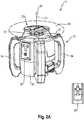
- FIGS. 2A-C show the rotating laser 11 in a three-dimensional representation ( FIG. 2A ) and the essential components of the rotary laser 11 in a schematic representation, wherein FIG. 2 B the components in a vertical plane parallel to the axis of rotation 21 and FIG. 2C represents the components in a horizontal plane perpendicular to the axis of rotation 21.
- the rotating laser 11 comprises a device housing 31 and a measuring device arranged in the device housing 31.
- the device housing 31 consists of a basic housing 32, a rotary head 33 and a plurality of handles 34.
- the rotary laser 11 is operated via an operating device 35 which is integrated in the basic housing 32 and can be operated from the outside.
- a remote control 36 can be provided, which can be connected to the rotating laser 11 via a communication link.
- the measuring device of the rotating laser 11 generates a laser beam in the interior of the basic housing 32, which is directed to one Rotation axis 21 rotating deflection optics 37 meets.
- a first part of the laser beam is deflected by 90 ° by the deflecting optics 37 and forms the first laser beam 22 of the rotating laser 11, which spans a laser plane 38 .
- a second part of the laser beam passes through the deflection optics 37 and forms the second laser beam 23 of the rotary laser 11.
- a rotary mode, a line mode and a point mode of the rotary laser become 11 distinguished.
- FIGS. 2 B , C show the essential components of the rotary laser 11 in a schematic representation.
- the rotating laser 11 comprises a laser device with a beam source 39, which generates a laser beam, and a collimation optics 40.
- the beam source 39 is designed, for example, as a semiconductor laser which generates the laser beam in the visible wavelength spectrum, for example a red laser beam with a wavelength of 635 nm or one green laser beam with a wavelength of 532 nm.
- the laser beam is collimated using the collimation optics 40.
- the collimation optics can be integrated in the beam source or, in the case of a beam source 39 with a high beam quality and low divergence, the collimation optics can be omitted.
- the collimated laser beam strikes the deflection optics 37, which separate the first and second laser beams 22, 23.
- the deflection optics 37 is connected to a rotating device 41 , which moves the deflection optics 37 about the axis of rotation 21.
- the rotating device 41 comprises a rotatable shaft 42, a motor unit 43 and a transmission device 44, which is designed, for example, in the form of a toothed belt and transmits the movement of the motor unit 43 to the shaft 42.
- the deflection optics 37 is coupled to the rotatable shaft 42 and is designed to be rotatable about the axis of rotation 21.
- the shaft 42 is mounted in a rotary bearing 45 of a stator part 46 which is connected to a spherical cap 47 .
- the spherical cap 47 is mounted in a spherical cap bearing 48 in a mounting frame 49 fixed to the housing so as to be tiltable about two pivot planes perpendicular to the plane of rotation (plane perpendicular to the axis of rotation 21).
- the rotating laser 11 comprises a measuring device 50 which measures the angle of rotation of the shaft 42 during the rotation about the axis of rotation 21.
- the measuring device 50 is designed, for example, as an angle encoder and consists of a measuring disk which is connected in a rotationally fixed manner to the shaft 42, a scanning device with which the measuring disk is scanned, and an evaluation and control element.
- the rotating laser 11 is designed as a horizontally and vertically usable rotating laser, wherein a horizontally and vertically usable rotating laser differs from a horizontally usable rotating laser by an additional device axis.
- the rotating laser 11 has a first horizontal axis 51 and a second horizontal axis as device axes 52 , which are perpendicular to each other and span a device level.
- the first and second horizontal axes 51, 52 are displayed on the rotary head 33 of the rotary laser 11 via display elements.
- the horizontally and vertically usable rotating laser 11 has, in addition to the first and second horizontal axes 51, 52, a further device axis, which is referred to as the vertical axis 53 and is ideally oriented perpendicular to the device plane of the first and second horizontal axes 51, 52.
- the rotating laser 11 is designed as a self-leveling rotating laser that levels itself automatically when the device housing 31 of the rotating laser 11 is set up within a self-leveling area.
- the self-leveling range of rotary lasers is typically 5 °.
- the rotating laser 11 comprises a leveling device which aligns the device axes of the rotating laser 11 in a defined state, regardless of an orientation of the device housing 31.
- the leveling device comprises a first leveling unit 55, which aligns the first horizontal axis 51 in a first defined state, a second leveling unit 56, which aligns the second horizontal axis 52 in a second defined state, and a third leveling unit 57, which aligns the vertical axis 53 in a third aligns defined state.
- the first leveling unit 55 comprises a first inclination sensor 58 and a first adjustment element
- the second leveling unit 56 comprises a second inclination sensor 59 and a second adjustment element
- the third leveling unit 57 comprises a third inclination sensor 60 and a third adjustment element.
- the adjustment elements of the leveling units 55, 56, 57 are integrated in an inclination device 61 , which has a first adjustment motor 62 and a second adjustment motor 63 .
- the first adjustment motor 62 inclines the mounting frame 49 about a first pivot axis, which coincides with the second horizontal axis 52
- the second adjustment motor 63 inclines the mounting frame 49 about a second pivot axis, which coincides with the first horizontal axis 51.
- the first adjustment motor 62 forms the first adjustment element of the first leveling unit 55 and the second adjustment motor 63 forms the second adjustment element of the second leveling unit 56. Since the vertical axis 53 is oriented perpendicular to the horizontal plane of the first and second horizontal axes 51, 52, the orientation of the vertical axis 53 can be can be set by means of the first and second adjustment motors 62, 63.
- the first and second adjustment motors 62, 63 together form the third adjustment element of the third leveling unit 57.
- the horizontal alignment of the laser plane or of the device plane represents a preferred defined state in which a rotating laser 11 is to be aligned in the horizontal position, the horizontally aligned device plane also being referred to as the horizontal plane.
- the vertical alignment of the laser plane or the device plane represents a preferred defined state in which a rotating laser 11 is aligned in the vertical position the vertical device level is also referred to as the vertical level.
- the laser plane 38, which the rotating first laser beam 22 generates, can be inclined by means of the inclination device 61 with respect to the horizontal plane or the vertical plane of the rotation laser 11.
- the rotating laser 11 can tilt the laser plane of the rotating first laser beam 22 in one tilt direction or in two tilt directions.
- the inclination of the laser plane takes place in the leveled state of the rotation laser 11.
- the rotation laser 11 can be inclined in the horizontal position or in the vertical position.
- FIGS. 3A , B show the laser receiver 12 in a three-dimensional representation ( FIG. 3A ) and the essential components of the laser receiver 12 as well as the interaction with the rotating laser 11 in a schematic representation ( FIG. 3B ).
- the laser receiver 12 is equipped with a measuring function which determines the distance of a laser beam from the zero position 19 of the detection field 18.
- the laser receiver 12 comprises a receiver housing 71, an operating device 72, an optical display 73, a loudspeaker 74 and the detection field 18 with which the incident position of a laser beam is detected.
- the detection field 18 has the detection height H D in the longitudinal direction 25 and the detection width B D in the transverse direction 26.
- the longitudinal direction 25 corresponds to the measuring direction of the laser receiver 12 and the transverse direction 26 is oriented perpendicular to the longitudinal direction 25, the longitudinal and transverse directions 25, 26 running parallel to the detection field 18.
- the operating device 72, the optical display 73, the loudspeaker 74 and the detection field 18 are integrated in the receiver housing 71 of the laser receiver 12.
- the operator can read information about the laser receiver 12 via the optical display 73. These include, for example, the state of charge of the laser receiver 12, information about the wireless communication link 13 to a rotating laser 11 and the set volume of the loudspeaker 74.
- the distance of a laser beam from the zero position 19 of the laser receiver 12 can be optically displayed as a numerical value.
- the distance of the laser beam can be communicated via the loudspeaker 74.
- the zero position 19 of the detection field 18 is displayed on the receiver housing 71 via marking notches 75 .
- FIG. 3B shows the essential components of the laser receiver 12 and the interaction of the laser receiver 12 with the rotating laser 11 in the form of a block diagram.
- the communication between the laser receiver 12 and the rotating laser 11 takes place via the communication connection 13, which connects a first transmitting / receiving unit 76 in the laser receiver 12 to a second transmitting / receiving unit 77 in the rotating laser 11.
- the first and second transceiver units 76, 77 are, for example, radio modules and the communication between the laser receiver 12 and the rotating laser 11 takes place via a communication link 13 designed as a radio link.
- the detection field 18, the optical display 73 and the loudspeaker 74 are connected to an evaluation device 78 which is arranged in the interior of the receiver housing 71.
- the evaluation device 78 is connected to a control device 79 for controlling the laser receiver 12, the evaluation device 78 and the control device 79 being integrated in a control device 81 , for example in the form of a microcontroller.
- the laser receiver 12 additionally comprises a sensor module 82 which is arranged in the interior of the receiver housing 71 and which is connected to the control device 81. With the aid of the sensor module 82, an inclination of the laser receiver 12 relative to the perpendicular direction 24 can be measured.
- the sensor module 82 comprises a 2-axis acceleration sensor or two 1-axis acceleration sensors.
- the components of the rotating laser 11 which are controlled by control elements or which are connected to an evaluation element include the beam source 39, the rotating device 41, the measuring device 50 and the leveling device 54 and, if present, the inclination device 61.
- a first control element 83 for control the beam source 39, a second control element 84 for controlling the rotating device 41, an evaluation and control element 85 for the measuring device 50, a third control element 86 for controlling the leveling device 54 and a fourth control element 87 for controlling the inclination device 61 can be designed as separate components or, as in FIG. 3B shown, can be integrated into a common control device 88, which is designed, for example, as a microcontroller.
- the control elements are connected to the components of the rotary laser 11 to be controlled via communication connections.
- the rotating laser 11 additionally comprises a temperature sensor 89, which is arranged in the device housing 31 of the rotating laser 11.
- the temperature sensor 89 measures the temperature in the device housing 31 and transmits the temperature to the control device 89 of the rotary laser 11. Since the orientation of the inclination sensors 58, 59, which align the first and second horizontal axes 51, 52 of the rotary laser 11 in the horizontal state, is temperature-dependent and the rotating laser 11 can be used in a wide temperature range, for example between -20 ° C. and +50 ° C., it is advantageous if a plurality of zero positions ⁇ are stored in the control device 88 of the rotating laser 11.
- first zero positions ⁇ 1 for the first inclination sensor 58 and several second zero positions ⁇ 2 for the second inclination sensor 59 can be recorded as a function of the temperature and stored in a characteristic curve or table.
- the measured temperature The associated zero position is read from the characteristic curve or table and the horizontal axis is aligned in the horizontal state defined by the zero position.
- FIGS. 4A-C show the device 10 of the FIG. 1 with the rotating laser 11 and the laser receiver 12 when executing the method according to the invention for checking the rotating laser 11 for cone errors.
- FIG. 4A shows the rotating laser 11 in a first position, in which the rotating laser 11 has a first measuring distance D 1 to the laser receiver 12
- FIG. 4B shows the rotating laser 11 in a second position, in which the rotating laser 11 has a second measuring distance D 2 from the laser receiver 12
- FIG. 4C shows the laser receiver 12 with the impingement positions of the rotating first laser beam 22 on the detection field 18 in the first and second location positions.
- the method according to the invention for checking the rotary laser 11 for cone errors is carried out in the horizontal position of the rotary laser 11 and in the longitudinal arrangement of the laser receiver 12.
- the rotating laser 11 is placed horizontally on the stand 14 or on a stable surface.
- the use of the stand 14 has the advantage that the method according to the invention is carried out at a height at which temperature fluctuations are lower than on the floor.
- the stand 14 enables an automatic height adjustment of the rotating laser 11 by means of the height adjustment device 16.
- the first and second horizontal axes 51, 52 are aligned in a horizontal state, the horizontal state of the first horizontal axis 51 being determined by the first zero position ⁇ 1 of the first inclination sensor 58 and the horizontal state of the second horizontal axis 52 the second zero position ⁇ 2 of the second inclination sensor 59 is fixed.
- the first horizontal axis 51 is aligned in the first zero position ⁇ 1 by means of the first leveling unit 55 and the second horizontal axis 52 is aligned in the second zero position ⁇ 2 by means of the second leveling unit 59.
- the first zero position ⁇ 1 for the first tilt sensor 58 and the second zero position ⁇ 2 for the second tilt sensor 59 are stored in the control device 89 of the rotary laser 11.
- the rotation laser 11 is checked for cone errors between a first measuring surface 91 and a second measuring surface 92 .
- the first and second measuring surfaces serve to determine the incident positions of the laser beam.
- the laser receiver 12 is fastened to a measuring stick 93 and comprises the second measuring surface 92.
- the first measuring surface 91 is integrated in a further laser receiver 94 , which is fastened to a further measuring stick 95 .
- the structure of the further laser receiver 94 corresponds to that of the laser receiver 12 and is equipped with a measuring function.
- the rotating laser 11 is arranged one after the other in the first and second position.
- the rotating laser 11 In the first position, the rotating laser 11 is set up in the first measuring distance D 1 to the second measuring surface 92 and the first horizontal axis 51 is aligned with the second measuring surface 92.
- the second horizontal axis 52 of the rotating laser 11 or any axis in the horizontal plane can be aligned with the second measuring surface 92.
- the axis which is aligned with the second measuring surface 92 in the first position is referred to as the measuring direction 96 .
- the rotating laser 11 In the second position, the rotating laser 11 is set up at the second measuring distance D 2 from the second measuring surface 92 and the measuring direction 96 is aligned with the second measuring surface 92.
- the first and second measuring distances D 1 , D 2 are measured between the axis of rotation 21 of the rotating laser 11 and the front of the detection field 18, which forms the second measuring surface 92.
- the first horizontal axis 51 of the rotating laser 11 is aligned with the second measuring surface 92 in the first and second position.
- the laser beam 22 rotates about the axis of rotation 21 and strikes the first measuring surface 91 and the second measuring surface 92.
- the position of the rotating laser beam 22 on the first measuring surface 91 is determined by the evaluation device of the further laser receiver 94 as the first control point 97 .
- the impact position of the rotating laser beam 21 on the second measuring surface 92 is determined by the evaluation device 78 of the laser receiver 12 as the second control point 98 and the distance between the second control point 98 and the zero position 19 of the detection field 18 is stored as the first height offset H 1 .
- the rotating laser 11 is moved from the first position to the second position ( FIG. 4B ).
- the laser beam 22 rotates about the axis of rotation 21 and strikes the first measuring surface 91 and the second measuring surface 92.
- the rotating laser 11 is adjusted in the height direction 15 by means of the height adjustment device of the stand 14 until the incident position of the laser beam 22 on the first Measuring surface 91 coincides with the first control point 96.
- the impact position of the rotating laser beam 22 on the second measuring surface 92 is determined by the evaluation device 78 of the laser receiver 12 as the third control point 99 and the distance between the third control point 99 and the zero position 19 of the detection field 18 is stored as the second height offset H 2 .
- the evaluation device 78 of the laser receiver 12 calculates the distance between the second control point 98 and the third control point 99 as the difference ⁇ from the first and second height offset H 1 , H 2 ( FIG. 4C ). As described, the evaluation can be carried out by the evaluation device 78 of the laser receiver 12. Alternatively, the evaluation can be carried out by a corresponding component in the rotating laser 11 or another component. If the evaluation is not carried out by the evaluation device 78 of the laser receiver 12, the second and third control points 98, 99 or the difference ⁇ transmitted to the corresponding component via a communication link.
- the first and second measuring distances D 1 , D 2 between the rotating laser 11 and the laser receiver 12 are determined in a first and / or second measuring method by means of the rotating laser 11 and the laser receiver 12.
- the first measuring distance D 1 between the rotating laser 11 and the laser receiver 12 is determined in the first location position and the second measuring distance D 2 between the rotating laser 11 and the laser receiver 12 is determined in the second location position.
- the measurement distances D 1 , D 2 can be determined as the first distance d 1 by means of a first measurement method, as the second distance d 2 by means of a second measurement method or as the mean distance d from the first and second distances d 1 , d 2 .
- the first and second distances d 1 , d 2 are determined in the horizontal position of the rotating laser 11 and the longitudinal arrangement of the laser receiver 12.
- the rotating laser 11 is operated in a rotating mode and the rotating first laser beam 22 is moved about the rotating axis 21 at a constant rotational speed v R.
- the second measurement method comprises the method steps: the rotating laser 11 is aligned horizontally and the first laser beam 22 rotates about the axis of rotation 21 at the constant rotational speed v R.
- the evaluation device 78 of the laser receiver 12 determines a signal length t s of the rotating first laser beam 22 on the detection field 18 of the laser receiver 12.
- the rotational speed v R is given in revolutions per minute and the time t full required for one revolution is 60 / V R.
- FIGS. 5A-C show three variants of the first measuring method with which the measuring distance between the rotating laser 11 and the laser receiver 12 is determined as the first distance d 1 .
- the first measuring method is used in the first location position in order to determine the first measuring distance D 1 between the rotating laser 11 and the laser receiver 12, and in the second location position to determine the second measurement distance D 2 between the rotating laser 11 and the laser receiver 12.
- the laser receiver 12 is aligned parallel to the perpendicular direction 24 and the first distance d 1 is measured between the axis of rotation 21 of the rotary laser 11 and a front side 101 of the detection field 18 of the laser receiver 12.
- the horizontal axes 51, 52 of the rotating laser 11 are in the horizontal state or are aligned in the horizontal state.
- the rotating laser 11 emits a horizontally aligned laser beam 102 .
- the rotating laser 11 is operated in a point mode and the laser beam is not moved about the axis of rotation 21.
- the laser beam is inclined by a known angle of inclination ⁇ and the position of the inclined laser beam on the detection field 18 of the laser receiver 12 is determined as the measurement point and the height offset of the measurement point is stored as the height.
- the inclination of the laser beam can be carried out by means of the leveling device 54 or the inclination device 61.
- the use of the leveling device 54 has the advantage that the measuring distance D can also be determined by rotating lasers 11 without an inclination device 61.
- the first measurement method assumes that the rotating laser 11 is aligned with the laser receiver 12 in such a way that the direction of inclination is approximately perpendicular to the detection field 18 of the laser receiver 12. Deviations from the vertical alignment lead to measurement errors that are tolerable for small deviations.
- the rotation laser 11 is oriented in the first and second position in the measuring direction 96 to the second measuring surface, wherein the first horizontal axis 51, the second horizontal axis 52 or any axis in the horizontal plane can be defined as the measuring direction 96. If the first or second horizontal axis 51, 52 is used as the measuring direction 96, the rotating laser 11 is arranged in a suitable angular position for the distance measurement.
- the laser beam 102 is inclined by means of the first leveling unit 55 if the first horizontal axis 51 is used as the measuring direction 96 and by means of the second leveling unit 56 if the second horizontal axis 52 is used as the measuring direction 96. If any axis in the horizontal plane is used as the measuring direction 96, the rotating laser 11 must be adjusted to a corresponding angular position (first or second horizontal axis 51, 52) for the distance measurement.
- FIG. 5A shows the first variant of the first measurement method.
- the horizontally aligned laser beam 102 is set to the zero position 19 of the laser receiver 12.
- the alignment of the laser beam 102 to the zero position 19 can be carried out, for example, with a height-adjustable stand. Is suitable for a fully automatic execution a tripod with a so-called “auto-alignment function", as described in the European patent EP 1 203 930 B1 is described.
- the laser beam is then inclined by means of the corresponding leveling unit of the leveling device 54 or the inclination device 61 by the inclination angle ⁇ .
- FIG. 5B shows the second variant of the first measurement method.
- the horizontally aligned laser beam 102 is emitted onto the detection field 18 of the laser receiver 12.
- FIG. 5C shows the third variant of the first measurement method.
- the horizontally aligned laser beam 102 is inclined in a positive inclination direction by the inclination angle ⁇ .
- the laser beam is then inclined in a negative inclination direction opposite to the positive inclination direction by a negative inclination angle - ⁇ .
- the formulas for calculating the measuring distance D between the rotating laser 11 and the laser receiver 12 and the formulas for calculating the correction angle ⁇ 1 when calibrating a horizontal axis apply to a laser receiver 12 which is parallel to the perpendicular direction 24 is aligned.
- the laser receiver 12 includes the sensor module 82 with which the inclination of the laser receiver 12 relative to the solder direction 24 is measured.
- FIGS. 6A , B show the alignment of the laser receiver 12 in a schematic representation, wherein the laser receiver 12 can be inclined to the plumb direction 24 by a first vertical angle ⁇ 1 and / or a second vertical angle ⁇ 2 . It shows FIG. 6A the laser receiver 12, which is inclined in a first vertical plane by the first vertical angle ⁇ 1 , and FIG. 6B the laser receiver 12, which is inclined in a second vertical plane by the second vertical angle ⁇ 2 .
- the first vertical plane is spanned by the perpendicular direction 24 and a normal vector 110 of the detection field 18 and the second vertical plane is spanned by the longitudinal direction 25 and the transverse direction 26 of the detection field 18.
- the first vertical angle ⁇ 1 is measured between the normal vector 110 and the solder direction 24, the first vertical angle ⁇ 1 representing the deviation of 90 ° between the normal vector 110 and the solder direction 24, and the second vertical angle ⁇ 2 is between the solder direction 24 and the Longitudinal direction 25 of the detection field 18 measured.
- a first laser beam strikes the detection field 18 of the laser receiver 12 and generates a first impact position 111.
- a second laser beam strikes the detection field 18 of the laser receiver 12 and generates a second impact position 112.
- the evaluation device 78 of the laser receiver 12 calculates a distance ⁇ l between the first impact position 111 and the second impingement position 112.
- the distance ⁇ l corresponds to the difference ⁇ from the first height offset H 1 and the second height offset H 2
- the distance ⁇ l corresponds to the height difference ⁇ h.
- the vertical distance v 1 in the vertical direction 24 in the first vertical plane is smaller than the distance ⁇ l which the detection field 18 of the laser receiver 12 has measured ( FIG. 6A ).
- the relationship ⁇ l ⁇ cos ( ⁇ 1 ) applies to the vertical distance v 1 .
- the vertical distance v 2 in the vertical direction 24 in the second vertical plane is smaller than the distance ⁇ l which the detection field 18 of the laser receiver 12 has measured ( FIG. 6B ).
- the relationship ⁇ l ⁇ cos ( ⁇ 2 ) applies to the vertical distance v 2 .
- the relationship ⁇ l ⁇ cos ( ⁇ 1 ) ⁇ cos ( ⁇ 2 ) applies to the vertical distance in the perpendicular direction 24.
- the distances ⁇ l are multiplied by a correction factor cos ( ⁇ 1 ) ⁇ cos ( ⁇ 2 ).
- the correction factor cos ( ⁇ 1 ) .cos ( ⁇ 2 ) is to be taken into account when measuring the distance of the first and second measuring distances D 1 , D 2 by means of the first measuring method and when determining the difference ⁇ between the second and third control points 98, 99.
- the second vertical angle ⁇ 2 should also be taken into account in the distance measurement using the second measurement method. Due to the inclination of the laser receiver 12 by the second vertical angle ⁇ 2 , the horizontal distance perpendicular to the perpendicular direction 24, which the rotating first laser beam 22 sweeps over the detection field 18, is greater than the detection width B D of the detection field 18 in the transverse direction 26. The signal length of the rotating The first laser beam 22 corresponds to the horizontal distance on the detection field 18. The relationship B D / cos ( ⁇ 2 ) applies to the horizontal distance. An inclination of the laser receiver 12 by the first vertical angle ⁇ 1 does not change the horizontal distance that the rotating first laser beam 22 traverses on the detection field 18.
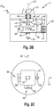
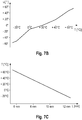
- FIGS. 7A-C show the construction of an optical inclination sensor 115 with a gas bubble 116 ( FIG. 7A ), a characteristic curve which represents the zero position u of the inclination sensor 115 as a function of a temperature T ( FIG. 7B ), and a further characteristic curve, which represents the temperature T as a function of a bubble length L of the gas bubble 116 ( FIG. 7C ).
- the temperatures of the inclination sensors 58, 59 can be measured.
- the temperature of the first inclination sensor 58 is referred to as the first temperature T 1 and the temperature of the second inclination sensor 59 as the second temperature T 2 .
- the temperature measurement takes place by means of the inclination sensors 58, 59.
- the temperature measurement by means of the inclination sensors 58, 59 has the advantage that the temperature T 1 , T 2 is measured exactly at the location in the device housing 31 of the rotary laser 11 which is used for the alignment of the first and second horizontal axis 51, 52 is relevant.
- FIG. 7A shows the components of the inclination sensor 115, which corresponds in structure to the inclination sensors 58, 59 of the rotary laser 11.
- the inclination sensor 115 comprises a housing 117, which is filled with the gas bubble 116 and a liquid 118 , a light source 119, a photodetector 120 and a spacer 121.
- the gas bubble 116 has a bubble length L, which is temperature-dependent and is therefore a measured variable for the temperature T is suitable.
- the bubble length L of the gas bubble 116 can be measured using the light source 119 and the photodetector 120.
- the components are provided with an index which is separated from the reference symbol by a hyphen.
- the first tilt sensor 58 has the index "1" and the second tilt sensor 59 has the index "2".
- FIG. 7B shows a characteristic curve which represents the zero position ⁇ of the inclination sensor 115 as a function of the temperature T.
- the characteristic curve establishes a relationship between the temperature of the inclination sensor 115 and the zero position ⁇ of the inclination sensor 115, which corresponds to the alignment in the defined state of the inclination sensor 115.
- a first characteristic curve which represents the first zero position ⁇ 1 of the first inclination sensor 58 as a function of the first temperature T 1
- a second characteristic curve which represents the second zero position ⁇ 2 of the second inclination sensor 59 as a function of the second Represents temperature T 2 , stored.
- FIG. 7C shows a further characteristic curve which represents the temperature T as a function of the bubble length L of the gas bubble 116.
- the characteristic curve establishes a relationship between the temperature T of the inclination sensor 115 and the bubble length L of the gas bubble 116 for the permitted temperature range of the rotary laser 11 from ⁇ 20 ° C. to + 50 ° C.
- the bubble length L of the gas bubble 116 changes linearly with the temperature T of the inclination sensor 115, the bubble length L decreasing as the temperature T decreases.
- control device 89 of the rotary laser 11 there is a further first characteristic curve, which represents the first temperature T 1 depending on the first bubble length L 1 of the first gas bubble 116-1, and a further second characteristic curve, which represents the second temperature T 2 depending on the second Represents bubble length L 2 of the second gas bubble 116 2 .
- the characteristic curve which represents the zero position u of the inclination sensor 115 as a function of the temperature T
- the control device 89 of the rotating laser 11 contains a first characteristic curve which represents the first zero position ⁇ 1 of the first inclination sensor 58 as a function of the first bubble length L 1 of the first gas bubble 116-1, and a second characteristic curve which represents the second zero position ⁇ 2 of the second inclination sensor 59 as a function of the second bubble length L 2 of the second gas bubble 116-2.
Landscapes
- Engineering & Computer Science (AREA)
- Physics & Mathematics (AREA)
- General Physics & Mathematics (AREA)
- Radar, Positioning & Navigation (AREA)
- Remote Sensing (AREA)
- Manufacturing & Machinery (AREA)
- Length Measuring Devices By Optical Means (AREA)
Claims (13)
- Procédé pour contrôler l'erreur de conicité d'un laser rotatif (11) avec un récepteur laser (12), dans lequel le laser rotatif (11) émet un faisceau laser (22) pouvant tourner dans un plan horizontal autour d'un axe de rotation (21), et le plan horizontal est défini par des premier et second axes horizontaux (51, 52), et le récepteur laser (12) a un champ de détection (18) avec une direction longitudinale (25) qui correspond à la direction de mesure, et une direction transversale (26), comportant les étapes consistant à :- placer le laser rotatif (11) à un premier emplacement entre une première surface de mesure (91) et une seconde surface de mesure (92), le laser rotatif (11) au premier emplacement ayant une première distance de mesure (D1) jusqu'à la seconde surface de mesure (92) et étant orienté vers la seconde surface de mesure (92) dans une direction de mesure (96),- orienter les axes horizontaux (51, 52) du laser rotatif (11) dans un état horizontal, l'état horizontal des axes horizontaux (51, 52) étant établi par une première position zéro (υ1) pour le premier axe horizontal (51) et une seconde position zéro (υ2) pour le second axe horizontal (52),- déterminer la position d'incidence du faisceau laser (22) sur la première surface de mesure (91) comme étant un premier point de contrôle (97),- déterminer, par le champ de détection (18) du récepteur laser (12), la position d'incidence du faisceau laser (22) sur la seconde surface de mesure (92) comme étant un deuxième point de contrôle (98), et mémoriser la distance du deuxième point de contrôle (98) jusqu'à une position zéro (19) du champ de détection (18) comme étant un premier décalage de hauteur (H1),- placer le laser rotatif (11) à un second emplacement entre la première surface de mesure (91) et la seconde surface de mesure (92), le laser rotatif (11) au second emplacement ayant une seconde distance de mesure (D2) par rapport à la seconde surface de mesure (92) et étant orienté vers la seconde surface de mesure (92) dans la direction de mesure (96),- disposer le laser rotatif (11) au second emplacement à une hauteur à laquelle la position d'incidence du faisceau laser (22) sur la première surface de mesure (91) correspond au premier point de contrôle (97),- déterminer, par le champ de détection (18) du récepteur laser (12), la position d'incidence du faisceau laser (22) sur la seconde surface de mesure (92) comme étant un troisième point de contrôle (99), et mémoriser la distance du troisième point de contrôle (99) jusqu'à la position zéro (19) du champ de détection (18) comme étant un second décalage de hauteur (H2),- calculer la distance entre le deuxième point de contrôle (97) et le troisième point de contrôle (98) comme étant la différence (Δ) entre les premier et second décalages de hauteur (H1, H2),- calculer une erreur de conicité (δ) à partir de la première distance de mesure (D1), de la seconde distance de mesure (D2) et de la différence (Δ) et- comparer l'erreur de conicité (δ) à une erreur maximale (δmax).
- Procédé selon la revendication 1, caractérisé en ce que la position d'incidence du faisceau laser (22) sur la première surface de mesure (91) au premier emplacement est déterminée par un récepteur laser supplémentaire (94).
- Procédé selon la revendication 2, caractérisé en ce que le réglage de hauteur du laser rotatif (11) s'effectue au second emplacement de manière commandée.
- Procédé selon la revendication 1, caractérisé en ce que la première distance de mesure (D1) au premier emplacement et/ou la seconde distance de mesure (D2) au second emplacement est déterminée au moyen du laser rotatif (11) et du récepteur laser (12) .
- Procédé selon la revendication 4, caractérisé en ce que la première et/ou seconde distance de mesure (D1, D2) est déterminée comme une première distance (d1) au moyen d'un premier procédé de mesure, comme une seconde distance (d2) au moyen d'un second procédé de mesure ou comme une distance (d) moyennée à partir des première et seconde distances (d1, d2).
- Procédé selon la revendication 5, caractérisé en ce que laser rotatif (11) est orienté horizontalement, le faisceau laser (102) orienté horizontalement est réglé sur la position zéro (19) du champ de détection (18), le faisceau laser en direction du récepteur laser (12) est incliné d'un angle d'inclinaison (α), la position d'incidence du faisceau laser incliné (103) sur le champ de détection (18) du récepteur laser (12) est déterminée comme étant un premier point de mesure (104), la distance du premier point de mesure (104) jusqu'à la position zéro (19) du champ de détection (18) est mémorisée en tant que première hauteur (h1 = h(α)) et la première distance (d1) est calculée à partir de l'angle d'inclinaison (α) et d'une différence de hauteur (Δh) entre la première hauteur (h1 = h(α)) et la position zéro (19) du champ de détection (18).
- Procédé selon la revendication 5, caractérisé en ce que le laser rotatif (11) est orienté horizontalement, la position d'incidence du faisceau laser (102) orienté horizontalement sur le champ de détection (18) du récepteur laser (12) est déterminée comme point de référence (105), la distance du point de référence (105) jusqu'à la position zéro (19) du champ de détection (18) est mémorisée en tant que hauteur de référence (h0), le faisceau laser est incliné d'un angle d'inclinaison (α), la position d'incidence du faisceau laser incliné (103) sur le champ de détection (108) est déterminée comme étant un premier point de mesure (107), la distance du premier point de mesure (107) jusqu'à la position zéro (19) du champ de détection (18) est mémorisée en tant que première hauteur (h1 = h(α)), et la première distance (d1) est calculée à partir de l'angle d'inclinaison (α) et d'une différence de hauteur (Δh = h1 - h0) entre la première hauteur (h1) et la hauteur de référence (h0).
- Procédé selon la revendication 5, caractérisé en ce que le laser rotatif (11) est orienté horizontalement, le faisceau laser (102) orienté horizontalement est incliné dans une direction d'inclinaison d'un angle d'inclinaison (α), la position d'incidence du faisceau laser incliné (103) sur le champ de détection (18) du récepteur laser (12) est déterminée comme étant un premier point de mesure (107), la distance du premier point de mesure (107) jusqu'à la position zéro (19) du champ de détection (18) est mémorisée en tant que première hauteur (h1 = h(α)), le faisceau laser dans une direction d'inclinaison orientée à l'opposé est incliné d'un angle d'inclinaison négatif (-α), la position d'incidence du faisceau laser incliné (108) sur le champ de détection (18) est déterminée comme étant un second point de mesure (109), la distance du second point de mesure (109) jusqu'à la position zéro (19) du champ de détection (18) est mémorisée en tant que seconde hauteur (h2 = h(-α)), et la première distance (d1) est calculée à partir de l'angle d'inclinaison (α) et d'une différence de hauteur (Δh = h1 - h2) entre la première hauteur (h1) et la seconde hauteur (h2).
- Procédé selon la revendication 5, caractérisé en ce que le laser rotatif (11) est orienté horizontalement, le faisceau laser (102) orienté horizontalement est tourné à une vitesse de rotation (vR) autour de l'axe de rotation (21), la longueur de signal du faisceau laser en rotation (22) sur le champ de détection (18) du récepteur laser (12) est déterminée et la seconde distance (d2) est calculée à partir de la vitesse de rotation (vR) du faisceau laser en rotation (22), de la longueur de signal (ts) du faisceau laser en rotation (22) et d'une largeur de détection (BD) du champ de détection (18).
- Procédé selon l'une des revendications 1 à 9, caractérisé en ce qu'une inclinaison du récepteur laser (12) par rapport à une direction d'aplomb (24) est déterminée en tant que premier angle vertical (Φ1) dans un premier plan vertical et/ou en tant que second angle vertical (Φ2) dans un second plan vertical, dans lequel le premier plan vertical est défini par la direction d'aplomb (24) et un vecteur normal (110) du champ de détection (18) du récepteur laser (12) et le second plan vertical est défini par une direction longitudinale (25) et une direction transversale (26) du champ de détection (18).
- Procédé selon la revendication 10, caractérisé en ce que, lors de l'évaluation avec le récepteur laser (12), le premier angle vertical (Φ1) et/ou le second angle vertical (Φ2) est multiplié par un facteur de correction (cos(Φ1), cos(Φ2), 1/cos(Φ2)) dépendant de l'angle.
- Procédé selon la revendication 1, caractérisé en ce que pour l'orientation des premier et second axes horizontaux (51, 52) à l'état horizontal, plusieurs premières et secondes positions zéro (υ1, υ2) sont enregistrées en fonction d'une température (T) ou d'une grandeur de mesure (L) dépendante de la température (T) et sont stockées dans une première et une seconde courbe caractéristique.
- Procédé selon la revendication 12, caractérisé en ce que la température (T) ou la grandeur de mesure (L) dépendante de la température (T) du laser rotatif (11) est mesurée, la position zéro (υ1, υ2) associée à la température (T) ou à la grandeur de mesure (L) est déterminée à partir de la courbe caractéristique, et les axes horizontaux (51, 52) sont orientés dans l'état horizontal défini par les positions zéro (υ1, υ2).
Applications Claiming Priority (2)
| Application Number | Priority Date | Filing Date | Title |
|---|---|---|---|
| EP15197022.5A EP3173738A1 (fr) | 2015-11-30 | 2015-11-30 | Procede de controle d'un laser rotatif afin de detecter une erreur de cone |
| PCT/EP2016/078489 WO2017093088A1 (fr) | 2015-11-30 | 2016-11-23 | Procédé de vérification d'un laser rotatif pour la détection d'erreurs de cône |
Publications (2)
| Publication Number | Publication Date |
|---|---|
| EP3384238A1 EP3384238A1 (fr) | 2018-10-10 |
| EP3384238B1 true EP3384238B1 (fr) | 2020-01-01 |
Family
ID=54707708
Family Applications (2)
| Application Number | Title | Priority Date | Filing Date |
|---|---|---|---|
| EP15197022.5A Withdrawn EP3173738A1 (fr) | 2015-11-30 | 2015-11-30 | Procede de controle d'un laser rotatif afin de detecter une erreur de cone |
| EP16800937.1A Active EP3384238B1 (fr) | 2015-11-30 | 2016-11-23 | Procede de controle d'un laser rotatif afin de detecter une erreur de cone |
Family Applications Before (1)
| Application Number | Title | Priority Date | Filing Date |
|---|---|---|---|
| EP15197022.5A Withdrawn EP3173738A1 (fr) | 2015-11-30 | 2015-11-30 | Procede de controle d'un laser rotatif afin de detecter une erreur de cone |
Country Status (5)
| Country | Link |
|---|---|
| US (1) | US10895472B2 (fr) |
| EP (2) | EP3173738A1 (fr) |
| JP (1) | JP6675485B2 (fr) |
| CN (1) | CN108291810B (fr) |
| WO (1) | WO2017093088A1 (fr) |
Families Citing this family (15)
| Publication number | Priority date | Publication date | Assignee | Title |
|---|---|---|---|---|
| US10066939B2 (en) | 2015-10-13 | 2018-09-04 | Stanley Black & Decker Inc. | Laser level |
| EP3173741A1 (fr) * | 2015-11-30 | 2017-05-31 | HILTI Aktiengesellschaft | Procede de controle et/ou d'etalonnage d'un axe horizontal d'un laser rotatif |
| EP3173739A1 (fr) * | 2015-11-30 | 2017-05-31 | HILTI Aktiengesellschaft | Procede de controle et/ou d'etalonnage d'un axe vertical d'un laser rotatif |
| CN107449446B (zh) * | 2017-08-30 | 2023-04-07 | 东莞欧达电子有限公司 | 一种激光准直设备的坡度测量系统及其测量方法 |
| JP7009198B2 (ja) * | 2017-12-19 | 2022-01-25 | 株式会社トプコン | 測量装置 |
| EP3674658A1 (fr) * | 2018-12-31 | 2020-07-01 | Hilti Aktiengesellschaft | Procédé de vérification et/ou d'étalonnage d'un axe horizontal d'un laser rotatif |
| US11320263B2 (en) | 2019-01-25 | 2022-05-03 | Stanley Black & Decker Inc. | Laser level system |
| CN110926344B (zh) * | 2019-12-04 | 2020-09-04 | 西华大学 | 测量事故车辆底盘硬点尺寸的专用设备及测量方法 |
| US12152882B2 (en) | 2020-12-01 | 2024-11-26 | Milwaukee Electric Tool Corporation | Laser level systems and controls |
| CN116391107A (zh) | 2020-12-01 | 2023-07-04 | 米沃奇电动工具公司 | 激光水平仪接口和控制件 |
| CN112648981B (zh) * | 2020-12-04 | 2023-01-13 | 中国航空工业集团公司成都飞机设计研究所 | 一种基于激光定位的旋转机构运动过程摆动量测量方法 |
| EP4015994B1 (fr) * | 2020-12-21 | 2024-09-18 | Leica Geosystems AG | Système de nivellement laser |
| CN112611398A (zh) * | 2020-12-31 | 2021-04-06 | 上海诺司纬光电仪器有限公司 | 用于校准激光扫平仪的装置和方法 |
| EP4323722A4 (fr) | 2021-04-12 | 2025-03-05 | Milwaukee Electric Tool Corporation | Système de niveau laser à alignement de détecteur automatique |
| CN113406653B (zh) * | 2021-06-15 | 2024-01-26 | 安徽理工大学 | 一种矿用本安型激光测距装置 |
Family Cites Families (7)
| Publication number | Priority date | Publication date | Assignee | Title |
|---|---|---|---|---|
| CH693579A5 (de) * | 1996-04-29 | 2003-10-15 | Ammann Lasertechnik | Laserstrahl-Nivelliereinrichtung sowie ein Verfahren zum Betrieb dieser Laserstrahl-Nivelliereinrichtung. |
| DE10054627C2 (de) | 2000-11-03 | 2002-10-31 | Nestle & Fischer Gmbh & Co Kg | Vorrichtung zum Ausrichten eines von einem Rotationslaser erzeugten Laserstrahls |
| JP4424665B2 (ja) * | 2004-07-30 | 2010-03-03 | 株式会社 ソキア・トプコン | 測量機 |
| JP2010156659A (ja) * | 2009-01-05 | 2010-07-15 | Audio Technica Corp | レーザー墨出し器の校正方法、校正プログラムおよび電子ジャイロ方式レーザー墨出し器 |
| EP2781880B1 (fr) * | 2013-03-19 | 2019-01-16 | Leica Geosystems AG | Système de laser de construction comportant une fonctionnalité de recalibrage s'exécutant de manière au moins partiellement automatique pour une fonctionnalité de mise à l'horizontale du rayon |
| EP2789973B1 (fr) * | 2013-04-12 | 2017-11-22 | Hexagon Technology Center GmbH | Laser à rotation avec lentille pouvant être déformée intentionnellement par des actionneurs |
| EP2833159A1 (fr) * | 2013-07-30 | 2015-02-04 | HILTI Aktiengesellschaft | Procédé pour calibrer un appareil de mesure |
-
2015
- 2015-11-30 EP EP15197022.5A patent/EP3173738A1/fr not_active Withdrawn
-
2016
- 2016-11-23 JP JP2018527881A patent/JP6675485B2/ja active Active
- 2016-11-23 CN CN201680070194.XA patent/CN108291810B/zh active Active
- 2016-11-23 US US15/778,583 patent/US10895472B2/en active Active
- 2016-11-23 WO PCT/EP2016/078489 patent/WO2017093088A1/fr not_active Ceased
- 2016-11-23 EP EP16800937.1A patent/EP3384238B1/fr active Active
Non-Patent Citations (1)
| Title |
|---|
| None * |
Also Published As
| Publication number | Publication date |
|---|---|
| WO2017093088A1 (fr) | 2017-06-08 |
| EP3173738A1 (fr) | 2017-05-31 |
| CN108291810A (zh) | 2018-07-17 |
| US10895472B2 (en) | 2021-01-19 |
| JP6675485B2 (ja) | 2020-04-01 |
| JP2018535424A (ja) | 2018-11-29 |
| US20180335316A1 (en) | 2018-11-22 |
| CN108291810B (zh) | 2020-09-25 |
| EP3384238A1 (fr) | 2018-10-10 |
Similar Documents
| Publication | Publication Date | Title |
|---|---|---|
| EP3384239B1 (fr) | Procede de controle et/ou d'etalonnage d'un axe horizontal d'un laser rotatif | |
| EP3384238B1 (fr) | Procede de controle d'un laser rotatif afin de detecter une erreur de cone | |
| EP3384236B1 (fr) | Procédé de contrôle et/ou d'étalonnage d'un axe vertical d'un laser rotatif | |
| EP3906390B1 (fr) | Procédé de vérification et/ou d'étalonnage d'un axe horizontal d'un laser rotatif | |
| EP3173740A1 (fr) | Procédé télémétrique entre un laser rotatif et un récepteur laser | |
| DE112006004097B4 (de) | Gerät und Verfahren zur Messung des Neigungswinkels | |
| EP1678468B1 (fr) | Procede pour verifier ou etalonner l'alignement dependant de sa position angulaire d'une eprouvette de haute precision | |
| EP3028063B1 (fr) | Procédé pour calibrer un appareil de mesure | |
| EP2998698A1 (fr) | Dispositif d'arpentage doté d'une fonction d'étalonnage des positions d'optique de focalisation réglables en fonction de la distance | |
| EP3236204A2 (fr) | Laser rotatif nivelable et son utilisation dans la mesure de machines-outils | |
| EP3384237A1 (fr) | Procédé d'orientation d'un axe d'appareil dans un état défini | |
| EP3384233A1 (fr) | Procédé de mesure d'une température de fonctionnement d'un appareil | |
| DE102006009404B3 (de) | Anordnung und Verfahren zur Positionsbestimmung mit einem Rotationslaser |
Legal Events
| Date | Code | Title | Description |
|---|---|---|---|
| STAA | Information on the status of an ep patent application or granted ep patent |
Free format text: STATUS: UNKNOWN |
|
| STAA | Information on the status of an ep patent application or granted ep patent |
Free format text: STATUS: THE INTERNATIONAL PUBLICATION HAS BEEN MADE |
|
| PUAI | Public reference made under article 153(3) epc to a published international application that has entered the european phase |
Free format text: ORIGINAL CODE: 0009012 |
|
| STAA | Information on the status of an ep patent application or granted ep patent |
Free format text: STATUS: REQUEST FOR EXAMINATION WAS MADE |
|
| 17P | Request for examination filed |
Effective date: 20180702 |
|
| AK | Designated contracting states |
Kind code of ref document: A1 Designated state(s): AL AT BE BG CH CY CZ DE DK EE ES FI FR GB GR HR HU IE IS IT LI LT LU LV MC MK MT NL NO PL PT RO RS SE SI SK SM TR |
|
| AX | Request for extension of the european patent |
Extension state: BA ME |
|
| DAV | Request for validation of the european patent (deleted) | ||
| DAX | Request for extension of the european patent (deleted) | ||
| GRAP | Despatch of communication of intention to grant a patent |
Free format text: ORIGINAL CODE: EPIDOSNIGR1 |
|
| STAA | Information on the status of an ep patent application or granted ep patent |
Free format text: STATUS: GRANT OF PATENT IS INTENDED |
|
| INTG | Intention to grant announced |
Effective date: 20190722 |
|
| GRAS | Grant fee paid |
Free format text: ORIGINAL CODE: EPIDOSNIGR3 |
|
| GRAA | (expected) grant |
Free format text: ORIGINAL CODE: 0009210 |
|
| STAA | Information on the status of an ep patent application or granted ep patent |
Free format text: STATUS: THE PATENT HAS BEEN GRANTED |
|
| AK | Designated contracting states |
Kind code of ref document: B1 Designated state(s): AL AT BE BG CH CY CZ DE DK EE ES FI FR GB GR HR HU IE IS IT LI LT LU LV MC MK MT NL NO PL PT RO RS SE SI SK SM TR |
|
| REG | Reference to a national code |
Ref country code: GB Ref legal event code: FG4D Free format text: NOT ENGLISH |
|
| REG | Reference to a national code |
Ref country code: CH Ref legal event code: EP Ref country code: AT Ref legal event code: REF Ref document number: 1220307 Country of ref document: AT Kind code of ref document: T Effective date: 20200115 |
|
| REG | Reference to a national code |
Ref country code: DE Ref legal event code: R096 Ref document number: 502016008280 Country of ref document: DE |
|
| REG | Reference to a national code |
Ref country code: IE Ref legal event code: FG4D Free format text: LANGUAGE OF EP DOCUMENT: GERMAN |
|
| REG | Reference to a national code |
Ref country code: NL Ref legal event code: MP Effective date: 20200101 |
|
| REG | Reference to a national code |
Ref country code: LT Ref legal event code: MG4D |
|
| PG25 | Lapsed in a contracting state [announced via postgrant information from national office to epo] |
Ref country code: RS Free format text: LAPSE BECAUSE OF FAILURE TO SUBMIT A TRANSLATION OF THE DESCRIPTION OR TO PAY THE FEE WITHIN THE PRESCRIBED TIME-LIMIT Effective date: 20200101 Ref country code: FI Free format text: LAPSE BECAUSE OF FAILURE TO SUBMIT A TRANSLATION OF THE DESCRIPTION OR TO PAY THE FEE WITHIN THE PRESCRIBED TIME-LIMIT Effective date: 20200101 Ref country code: NO Free format text: LAPSE BECAUSE OF FAILURE TO SUBMIT A TRANSLATION OF THE DESCRIPTION OR TO PAY THE FEE WITHIN THE PRESCRIBED TIME-LIMIT Effective date: 20200401 Ref country code: NL Free format text: LAPSE BECAUSE OF FAILURE TO SUBMIT A TRANSLATION OF THE DESCRIPTION OR TO PAY THE FEE WITHIN THE PRESCRIBED TIME-LIMIT Effective date: 20200101 Ref country code: CZ Free format text: LAPSE BECAUSE OF FAILURE TO SUBMIT A TRANSLATION OF THE DESCRIPTION OR TO PAY THE FEE WITHIN THE PRESCRIBED TIME-LIMIT Effective date: 20200101 Ref country code: LT Free format text: LAPSE BECAUSE OF FAILURE TO SUBMIT A TRANSLATION OF THE DESCRIPTION OR TO PAY THE FEE WITHIN THE PRESCRIBED TIME-LIMIT Effective date: 20200101 Ref country code: PT Free format text: LAPSE BECAUSE OF FAILURE TO SUBMIT A TRANSLATION OF THE DESCRIPTION OR TO PAY THE FEE WITHIN THE PRESCRIBED TIME-LIMIT Effective date: 20200527 |
|
| PG25 | Lapsed in a contracting state [announced via postgrant information from national office to epo] |
Ref country code: BG Free format text: LAPSE BECAUSE OF FAILURE TO SUBMIT A TRANSLATION OF THE DESCRIPTION OR TO PAY THE FEE WITHIN THE PRESCRIBED TIME-LIMIT Effective date: 20200401 Ref country code: LV Free format text: LAPSE BECAUSE OF FAILURE TO SUBMIT A TRANSLATION OF THE DESCRIPTION OR TO PAY THE FEE WITHIN THE PRESCRIBED TIME-LIMIT Effective date: 20200101 Ref country code: SE Free format text: LAPSE BECAUSE OF FAILURE TO SUBMIT A TRANSLATION OF THE DESCRIPTION OR TO PAY THE FEE WITHIN THE PRESCRIBED TIME-LIMIT Effective date: 20200101 Ref country code: IS Free format text: LAPSE BECAUSE OF FAILURE TO SUBMIT A TRANSLATION OF THE DESCRIPTION OR TO PAY THE FEE WITHIN THE PRESCRIBED TIME-LIMIT Effective date: 20200501 Ref country code: HR Free format text: LAPSE BECAUSE OF FAILURE TO SUBMIT A TRANSLATION OF THE DESCRIPTION OR TO PAY THE FEE WITHIN THE PRESCRIBED TIME-LIMIT Effective date: 20200101 Ref country code: GR Free format text: LAPSE BECAUSE OF FAILURE TO SUBMIT A TRANSLATION OF THE DESCRIPTION OR TO PAY THE FEE WITHIN THE PRESCRIBED TIME-LIMIT Effective date: 20200402 |
|
| REG | Reference to a national code |
Ref country code: DE Ref legal event code: R097 Ref document number: 502016008280 Country of ref document: DE |
|
| PG25 | Lapsed in a contracting state [announced via postgrant information from national office to epo] |
Ref country code: DK Free format text: LAPSE BECAUSE OF FAILURE TO SUBMIT A TRANSLATION OF THE DESCRIPTION OR TO PAY THE FEE WITHIN THE PRESCRIBED TIME-LIMIT Effective date: 20200101 Ref country code: SK Free format text: LAPSE BECAUSE OF FAILURE TO SUBMIT A TRANSLATION OF THE DESCRIPTION OR TO PAY THE FEE WITHIN THE PRESCRIBED TIME-LIMIT Effective date: 20200101 Ref country code: ES Free format text: LAPSE BECAUSE OF FAILURE TO SUBMIT A TRANSLATION OF THE DESCRIPTION OR TO PAY THE FEE WITHIN THE PRESCRIBED TIME-LIMIT Effective date: 20200101 Ref country code: RO Free format text: LAPSE BECAUSE OF FAILURE TO SUBMIT A TRANSLATION OF THE DESCRIPTION OR TO PAY THE FEE WITHIN THE PRESCRIBED TIME-LIMIT Effective date: 20200101 Ref country code: SM Free format text: LAPSE BECAUSE OF FAILURE TO SUBMIT A TRANSLATION OF THE DESCRIPTION OR TO PAY THE FEE WITHIN THE PRESCRIBED TIME-LIMIT Effective date: 20200101 Ref country code: EE Free format text: LAPSE BECAUSE OF FAILURE TO SUBMIT A TRANSLATION OF THE DESCRIPTION OR TO PAY THE FEE WITHIN THE PRESCRIBED TIME-LIMIT Effective date: 20200101 |
|
| PLBE | No opposition filed within time limit |
Free format text: ORIGINAL CODE: 0009261 |
|
| STAA | Information on the status of an ep patent application or granted ep patent |
Free format text: STATUS: NO OPPOSITION FILED WITHIN TIME LIMIT |
|
| 26N | No opposition filed |
Effective date: 20201002 |
|
| PG25 | Lapsed in a contracting state [announced via postgrant information from national office to epo] |
Ref country code: SI Free format text: LAPSE BECAUSE OF FAILURE TO SUBMIT A TRANSLATION OF THE DESCRIPTION OR TO PAY THE FEE WITHIN THE PRESCRIBED TIME-LIMIT Effective date: 20200101 Ref country code: PL Free format text: LAPSE BECAUSE OF FAILURE TO SUBMIT A TRANSLATION OF THE DESCRIPTION OR TO PAY THE FEE WITHIN THE PRESCRIBED TIME-LIMIT Effective date: 20200101 |
|
| PG25 | Lapsed in a contracting state [announced via postgrant information from national office to epo] |
Ref country code: MC Free format text: LAPSE BECAUSE OF FAILURE TO SUBMIT A TRANSLATION OF THE DESCRIPTION OR TO PAY THE FEE WITHIN THE PRESCRIBED TIME-LIMIT Effective date: 20200101 |
|
| PG25 | Lapsed in a contracting state [announced via postgrant information from national office to epo] |
Ref country code: LU Free format text: LAPSE BECAUSE OF NON-PAYMENT OF DUE FEES Effective date: 20201123 |
|
| REG | Reference to a national code |
Ref country code: BE Ref legal event code: MM Effective date: 20201130 |
|
| PG25 | Lapsed in a contracting state [announced via postgrant information from national office to epo] |
Ref country code: IE Free format text: LAPSE BECAUSE OF NON-PAYMENT OF DUE FEES Effective date: 20201123 |
|
| PG25 | Lapsed in a contracting state [announced via postgrant information from national office to epo] |
Ref country code: TR Free format text: LAPSE BECAUSE OF FAILURE TO SUBMIT A TRANSLATION OF THE DESCRIPTION OR TO PAY THE FEE WITHIN THE PRESCRIBED TIME-LIMIT Effective date: 20200101 Ref country code: MT Free format text: LAPSE BECAUSE OF FAILURE TO SUBMIT A TRANSLATION OF THE DESCRIPTION OR TO PAY THE FEE WITHIN THE PRESCRIBED TIME-LIMIT Effective date: 20200101 Ref country code: CY Free format text: LAPSE BECAUSE OF FAILURE TO SUBMIT A TRANSLATION OF THE DESCRIPTION OR TO PAY THE FEE WITHIN THE PRESCRIBED TIME-LIMIT Effective date: 20200101 |
|
| PG25 | Lapsed in a contracting state [announced via postgrant information from national office to epo] |
Ref country code: MK Free format text: LAPSE BECAUSE OF FAILURE TO SUBMIT A TRANSLATION OF THE DESCRIPTION OR TO PAY THE FEE WITHIN THE PRESCRIBED TIME-LIMIT Effective date: 20200101 Ref country code: AL Free format text: LAPSE BECAUSE OF FAILURE TO SUBMIT A TRANSLATION OF THE DESCRIPTION OR TO PAY THE FEE WITHIN THE PRESCRIBED TIME-LIMIT Effective date: 20200101 |
|
| PG25 | Lapsed in a contracting state [announced via postgrant information from national office to epo] |
Ref country code: BE Free format text: LAPSE BECAUSE OF NON-PAYMENT OF DUE FEES Effective date: 20201130 |
|
| REG | Reference to a national code |
Ref country code: CH Ref legal event code: U11 Free format text: ST27 STATUS EVENT CODE: U-0-0-U10-U11 (AS PROVIDED BY THE NATIONAL OFFICE) Effective date: 20251201 |
|
| PGFP | Annual fee paid to national office [announced via postgrant information from national office to epo] |
Ref country code: DE Payment date: 20251119 Year of fee payment: 10 |
|
| PGFP | Annual fee paid to national office [announced via postgrant information from national office to epo] |
Ref country code: GB Payment date: 20251121 Year of fee payment: 10 |
|
| PGFP | Annual fee paid to national office [announced via postgrant information from national office to epo] |
Ref country code: AT Payment date: 20251120 Year of fee payment: 10 |
|
| PGFP | Annual fee paid to national office [announced via postgrant information from national office to epo] |
Ref country code: IT Payment date: 20251125 Year of fee payment: 10 |
|
| PGFP | Annual fee paid to national office [announced via postgrant information from national office to epo] |
Ref country code: FR Payment date: 20251126 Year of fee payment: 10 |
|
| PGFP | Annual fee paid to national office [announced via postgrant information from national office to epo] |
Ref country code: CH Payment date: 20251201 Year of fee payment: 10 |