EP3385026A1 - Structure de surface portante et procédé de fabrication - Google Patents
Structure de surface portante et procédé de fabrication Download PDFInfo
- Publication number
- EP3385026A1 EP3385026A1 EP18161954.5A EP18161954A EP3385026A1 EP 3385026 A1 EP3385026 A1 EP 3385026A1 EP 18161954 A EP18161954 A EP 18161954A EP 3385026 A1 EP3385026 A1 EP 3385026A1
- Authority
- EP
- European Patent Office
- Prior art keywords
- airfoil
- cover
- airfoil body
- stud
- bore
- Prior art date
- Legal status (The legal status is an assumption and is not a legal conclusion. Google has not performed a legal analysis and makes no representation as to the accuracy of the status listed.)
- Granted
Links
Images



Classifications
-
- F—MECHANICAL ENGINEERING; LIGHTING; HEATING; WEAPONS; BLASTING
- F01—MACHINES OR ENGINES IN GENERAL; ENGINE PLANTS IN GENERAL; STEAM ENGINES
- F01D—NON-POSITIVE DISPLACEMENT MACHINES OR ENGINES, e.g. STEAM TURBINES
- F01D5/00—Blades; Blade-carrying members; Heating, heat-insulating, cooling or antivibration means on the blades or the members
- F01D5/12—Blades
- F01D5/14—Form or construction
- F01D5/147—Construction, i.e. structural features, e.g. of weight-saving hollow blades
-
- B—PERFORMING OPERATIONS; TRANSPORTING
- B21—MECHANICAL METAL-WORKING WITHOUT ESSENTIALLY REMOVING MATERIAL; PUNCHING METAL
- B21J—FORGING; HAMMERING; PRESSING METAL; RIVETING; FORGE FURNACES
- B21J15/00—Riveting
- B21J15/02—Riveting procedures
- B21J15/027—Setting rivets by friction heating
-
- B—PERFORMING OPERATIONS; TRANSPORTING
- B23—MACHINE TOOLS; METAL-WORKING NOT OTHERWISE PROVIDED FOR
- B23K—SOLDERING OR UNSOLDERING; WELDING; CLADDING OR PLATING BY SOLDERING OR WELDING; CUTTING BY APPLYING HEAT LOCALLY, e.g. FLAME CUTTING; WORKING BY LASER BEAM
- B23K1/00—Soldering, e.g. brazing, or unsoldering
- B23K1/0008—Soldering, e.g. brazing, or unsoldering specially adapted for particular articles or work
- B23K1/0018—Brazing of turbine parts
-
- B—PERFORMING OPERATIONS; TRANSPORTING
- B23—MACHINE TOOLS; METAL-WORKING NOT OTHERWISE PROVIDED FOR
- B23K—SOLDERING OR UNSOLDERING; WELDING; CLADDING OR PLATING BY SOLDERING OR WELDING; CUTTING BY APPLYING HEAT LOCALLY, e.g. FLAME CUTTING; WORKING BY LASER BEAM
- B23K20/00—Non-electric welding by applying impact or other pressure, with or without the application of heat, e.g. cladding or plating
- B23K20/12—Non-electric welding by applying impact or other pressure, with or without the application of heat, e.g. cladding or plating the heat being generated by friction; Friction welding
- B23K20/122—Non-electric welding by applying impact or other pressure, with or without the application of heat, e.g. cladding or plating the heat being generated by friction; Friction welding using a non-consumable tool, e.g. friction stir welding
- B23K20/127—Friction stir welding involving a mechanical connection
-
- B—PERFORMING OPERATIONS; TRANSPORTING
- B23—MACHINE TOOLS; METAL-WORKING NOT OTHERWISE PROVIDED FOR
- B23K—SOLDERING OR UNSOLDERING; WELDING; CLADDING OR PLATING BY SOLDERING OR WELDING; CUTTING BY APPLYING HEAT LOCALLY, e.g. FLAME CUTTING; WORKING BY LASER BEAM
- B23K20/00—Non-electric welding by applying impact or other pressure, with or without the application of heat, e.g. cladding or plating
- B23K20/12—Non-electric welding by applying impact or other pressure, with or without the application of heat, e.g. cladding or plating the heat being generated by friction; Friction welding
- B23K20/129—Non-electric welding by applying impact or other pressure, with or without the application of heat, e.g. cladding or plating the heat being generated by friction; Friction welding specially adapted for particular articles or work
- B23K20/1295—Welding studs
-
- B—PERFORMING OPERATIONS; TRANSPORTING
- B23—MACHINE TOOLS; METAL-WORKING NOT OTHERWISE PROVIDED FOR
- B23K—SOLDERING OR UNSOLDERING; WELDING; CLADDING OR PLATING BY SOLDERING OR WELDING; CUTTING BY APPLYING HEAT LOCALLY, e.g. FLAME CUTTING; WORKING BY LASER BEAM
- B23K20/00—Non-electric welding by applying impact or other pressure, with or without the application of heat, e.g. cladding or plating
- B23K20/22—Non-electric welding by applying impact or other pressure, with or without the application of heat, e.g. cladding or plating taking account of the properties of the materials to be welded
- B23K20/233—Non-electric welding by applying impact or other pressure, with or without the application of heat, e.g. cladding or plating taking account of the properties of the materials to be welded without ferrous layer
-
- B—PERFORMING OPERATIONS; TRANSPORTING
- B23—MACHINE TOOLS; METAL-WORKING NOT OTHERWISE PROVIDED FOR
- B23K—SOLDERING OR UNSOLDERING; WELDING; CLADDING OR PLATING BY SOLDERING OR WELDING; CUTTING BY APPLYING HEAT LOCALLY, e.g. FLAME CUTTING; WORKING BY LASER BEAM
- B23K2101/00—Articles made by soldering, welding or cutting
- B23K2101/001—Turbines
-
- B—PERFORMING OPERATIONS; TRANSPORTING
- B23—MACHINE TOOLS; METAL-WORKING NOT OTHERWISE PROVIDED FOR
- B23K—SOLDERING OR UNSOLDERING; WELDING; CLADDING OR PLATING BY SOLDERING OR WELDING; CUTTING BY APPLYING HEAT LOCALLY, e.g. FLAME CUTTING; WORKING BY LASER BEAM
- B23K2103/00—Materials to be soldered, welded or cut
- B23K2103/08—Non-ferrous metals or alloys
- B23K2103/10—Aluminium or alloys thereof
-
- B—PERFORMING OPERATIONS; TRANSPORTING
- B23—MACHINE TOOLS; METAL-WORKING NOT OTHERWISE PROVIDED FOR
- B23K—SOLDERING OR UNSOLDERING; WELDING; CLADDING OR PLATING BY SOLDERING OR WELDING; CUTTING BY APPLYING HEAT LOCALLY, e.g. FLAME CUTTING; WORKING BY LASER BEAM
- B23K2103/00—Materials to be soldered, welded or cut
- B23K2103/08—Non-ferrous metals or alloys
- B23K2103/14—Titanium or alloys thereof
-
- B—PERFORMING OPERATIONS; TRANSPORTING
- B23—MACHINE TOOLS; METAL-WORKING NOT OTHERWISE PROVIDED FOR
- B23K—SOLDERING OR UNSOLDERING; WELDING; CLADDING OR PLATING BY SOLDERING OR WELDING; CUTTING BY APPLYING HEAT LOCALLY, e.g. FLAME CUTTING; WORKING BY LASER BEAM
- B23K2103/00—Materials to be soldered, welded or cut
- B23K2103/18—Dissimilar materials
- B23K2103/26—Alloys of Nickel and Cobalt and Chromium
-
- F—MECHANICAL ENGINEERING; LIGHTING; HEATING; WEAPONS; BLASTING
- F05—INDEXING SCHEMES RELATING TO ENGINES OR PUMPS IN VARIOUS SUBCLASSES OF CLASSES F01-F04
- F05D—INDEXING SCHEME FOR ASPECTS RELATING TO NON-POSITIVE-DISPLACEMENT MACHINES OR ENGINES, GAS-TURBINES OR JET-PROPULSION PLANTS
- F05D2220/00—Application
- F05D2220/30—Application in turbines
- F05D2220/36—Application in turbines specially adapted for the fan of turbofan engines
-
- F—MECHANICAL ENGINEERING; LIGHTING; HEATING; WEAPONS; BLASTING
- F05—INDEXING SCHEMES RELATING TO ENGINES OR PUMPS IN VARIOUS SUBCLASSES OF CLASSES F01-F04
- F05D—INDEXING SCHEME FOR ASPECTS RELATING TO NON-POSITIVE-DISPLACEMENT MACHINES OR ENGINES, GAS-TURBINES OR JET-PROPULSION PLANTS
- F05D2230/00—Manufacture
- F05D2230/20—Manufacture essentially without removing material
- F05D2230/23—Manufacture essentially without removing material by permanently joining parts together
- F05D2230/232—Manufacture essentially without removing material by permanently joining parts together by welding
- F05D2230/237—Brazing
-
- F—MECHANICAL ENGINEERING; LIGHTING; HEATING; WEAPONS; BLASTING
- F05—INDEXING SCHEMES RELATING TO ENGINES OR PUMPS IN VARIOUS SUBCLASSES OF CLASSES F01-F04
- F05D—INDEXING SCHEME FOR ASPECTS RELATING TO NON-POSITIVE-DISPLACEMENT MACHINES OR ENGINES, GAS-TURBINES OR JET-PROPULSION PLANTS
- F05D2230/00—Manufacture
- F05D2230/20—Manufacture essentially without removing material
- F05D2230/23—Manufacture essentially without removing material by permanently joining parts together
- F05D2230/232—Manufacture essentially without removing material by permanently joining parts together by welding
- F05D2230/239—Inertia or friction welding
-
- Y—GENERAL TAGGING OF NEW TECHNOLOGICAL DEVELOPMENTS; GENERAL TAGGING OF CROSS-SECTIONAL TECHNOLOGIES SPANNING OVER SEVERAL SECTIONS OF THE IPC; TECHNICAL SUBJECTS COVERED BY FORMER USPC CROSS-REFERENCE ART COLLECTIONS [XRACs] AND DIGESTS
- Y02—TECHNOLOGIES OR APPLICATIONS FOR MITIGATION OR ADAPTATION AGAINST CLIMATE CHANGE
- Y02T—CLIMATE CHANGE MITIGATION TECHNOLOGIES RELATED TO TRANSPORTATION
- Y02T50/00—Aeronautics or air transport
- Y02T50/60—Efficient propulsion technologies, e.g. for aircraft
Definitions
- the present disclosure relates to airfoils, and more specifically, to structure and methods of attaching a cover to an airfoil.
- a gas turbine engine typically includes a fan section, a compressor section, a combustor section, and a turbine section.
- a fan section may drive air along a bypass flowpath while a compressor section may drive air along a core flowpath.
- air is pressurized in the compressor section and is mixed with fuel and burned in the combustor section to generate hot combustion gases.
- the hot combustion gases flow through the turbine section, which extracts energy from the hot combustion gases to power the compressor section and other gas turbine engine loads.
- the compressor section typically includes low pressure and high pressure compressors, and the turbine section includes low pressure and high pressure turbines.
- Some airfoils have covers that are attached to a pressure side or a suction side of the airfoil.
- an airfoil body may be manufactured to have various recesses or cavities, which may be for weight reduction, balance, cooling, etc.
- a cover may be attached to the airfoil body to extend over the recesses or cavities.
- conventional methods of manufacturing airfoils with covers have various shortcomings.
- the present disclosure provides an airfoil.
- the airfoil may include an airfoil body, a cover disposed on at least one of a suction side and a pressure side of the airfoil body, and a stud extending through the cover and into the airfoil body.
- the stud may be joined to the airfoil body and the cover by a friction weld.
- the stud is a first stud and the airfoil further comprises a second stud extending through the cover an into the airfoil body.
- the stud extends completely through the cover and completely through the airfoil body from the suction side to the pressure side of the airfoil body.
- the airfoil body defines a recess formed in at least one of the suction side and the pressure side of the airfoil body, wherein the cover extends across an opening of the recess.
- the airfoil body may include a rib that extends through the recess and the stud may extend into the rib of the airfoil body.
- the airfoil further includes a braze filler material joining the cover to the airfoil body. In various embodiments, the airfoil further includes an anti-corrosion compound disposed in a seam between the cover and the airfoil body. In various embodiments, an anti-erosion compound disposed in a seam between the cover and the airfoil body.
- the method may include forming a first bore in an airfoil body, the first bore having a first diameter.
- the method may include forming a second bore in a cover, the second bore having a second diameter.
- the method may still further include positioning the cover adjacent the airfoil body so that a first bore axis of the first bore is collinear with a second bore axis of the second bore.
- the method may also include rotatably forcing a stud through the second bore and the first bore to friction weld the cover to the stud and the airfoil body to the stud, wherein before rotatably forcing the stud, the stud has a third diameter that is equal to or greater than the first diameter and the second diameter.
- the method includes forming a recess in at least one of a pressure side and a suction side of the airfoil body. Positioning the cover adjacent the airfoil body may include extending the cover across an opening of the recess. In various embodiments, forming the recess includes forming a rib that extends through the recess such that the first bore is formed in the rib. The first bore may be a pass-through bore that extends completely through the airfoil body from a suction side to a pressure side of the airfoil body. In various embodiments, the method may further include applying a braze filler material between respective mating surfaces of the cover and the airfoil body. The method may further include heating the braze filler material to seal braze the cover to the airfoil body.
- the method further includes applying a protective filler material in a seam between the cover and the airfoil body.
- applying the protective filler material is performed after heating the braze filler material.
- applying the protective filler material includes various sub-steps, including applying an anti-corrosion compound in the seam, after applying the anti-corrosion compound in the seam, curing the anti-corrosion compound, and, after curing the anti-corrosion compound, applying an anti-erosion compound over the anti-corrosion compound.
- a gas turbine engine that includes a fan section having a plurality of fan blades.
- Each fan blade of the plurality of fan blades may include a cover that is joined to an airfoil body by one or more friction stud welds.
- the cover is exclusively structurally joined to the airfoil body via the one or more friction stud welds.
- aft refers to the direction associated with the exhaust (e.g., the back end) of a gas turbine engine.
- forward refers to the direction associated with the intake (e.g., the front end) of a gas turbine engine.
- a first component that is "axially outward" of a second component means that a first component is positioned at a greater distance in the aft or forward direction away from the longitudinal center of the gas turbine along the longitudinal axis of the gas turbine, than the second component.
- a first component that is "axially inward” of a second component means that the first component is positioned closer to the longitudinal center of the gas turbine along the longitudinal axis of the gas turbine, than the second component.
- a first component that is "radially outward" of a second component means that the first component is positioned at a greater distance away from the engine central longitudinal axis than the second component.
- a first component that is “radially inward” of a second component means that the first component is positioned closer to the engine central longitudinal axis than the second component.
- a first component that is radially inward of a second component rotates through a circumferentially shorter path than the second component.
- the terminology “radially outward” and “radially inward” may also be used relative to references other than the engine central longitudinal axis. For example, a first component of a combustor that is radially inward or radially outward of a second component of a combustor is positioned relative to the central longitudinal axis of the combustor.
- Gas turbine engine 20 may be a two-spool turbofan that generally incorporates a fan section 22, a compressor section 24, a combustor section 26 and a turbine section 28.
- Alternative engines may include, for example, an augmentor section among other systems or features.
- fan section 22 can drive coolant (e.g., air) along a path of bypass airflow B while compressor section 24 can drive coolant along a core flowpath C for compression and communication into combustor section 26 then expansion through turbine section 28.
- coolant e.g., air
- compressor section 24 can drive coolant along a core flowpath C for compression and communication into combustor section 26 then expansion through turbine section 28.
- Gas turbine engine 20 may generally comprise a low speed spool 30 and a high speed spool 32 mounted for rotation about an engine central longitudinal axis A-A' relative to an engine static structure 36 or engine case via several bearing systems 38, 38-1, and 38-2.
- Engine central longitudinal axis A-A' is oriented in the z direction on the provided x-y-z axes.
- various bearing systems 38 at various locations may alternatively or additionally be provided, including for example, bearing system 38, bearing system 38-1, and bearing system 38-2.
- Low speed spool 30 may generally comprise an inner shaft 40 that interconnects a fan 42, a low pressure compressor 44 and a low pressure turbine 46.
- Inner shaft 40 may be connected to fan 42 through a geared architecture 48 that can drive fan 42 at a lower speed than low speed spool 30.
- Geared architecture 48 may comprise a gear assembly 60 enclosed within a gear housing 62.
- Gear assembly 60 couples inner shaft 40 to a rotating fan structure.
- High speed spool 32 may comprise an outer shaft 50 that interconnects a high pressure compressor 52 and high pressure turbine 54.
- a combustor 56 may be located between high pressure compressor 52 and high pressure turbine 54.
- a mid-turbine frame 57 of engine static structure 36 may be located generally between high pressure turbine 54 and low pressure turbine 46.
- Mid-turbine frame 57 may support one or more bearing systems 38 in turbine section 28.
- Inner shaft 40 and outer shaft 50 may be concentric and rotate via bearing systems 38 about the engine central longitudinal axis A-A', which is collinear with their longitudinal axes.
- A-A' the engine central longitudinal axis A-A'
- the airflow of core flowpath C may be compressed by low pressure compressor 44 then high pressure compressor 52, mixed and burned with fuel in combustor 56, then expanded over high pressure turbine 54 and low pressure turbine 46.
- Turbines 46, 54 rotationally drive the respective low speed spool 30 and high speed spool 32 in response to the expansion.
- Gas turbine engine 20 may be, for example, a high-bypass ratio geared aircraft engine. In various embodiments, the bypass ratio of gas turbine engine 20 may be greater than about six (6). In various embodiments, the bypass ratio of gas turbine engine 20 may be greater than ten (10).
- geared architecture 48 may be an epicyclic gear train, such as a star gear system (sun gear in meshing engagement with a plurality of star gears supported by a carrier and in meshing engagement with a ring gear) or other gear system. Geared architecture 48 may have a gear reduction ratio of greater than about 2.3 and low pressure turbine 46 may have a pressure ratio that is greater than about five (5). In various embodiments, the bypass ratio of gas turbine engine 20 is greater than about ten (10:1).
- the diameter of fan 42 may be significantly larger than that of the low pressure compressor 44, and the low pressure turbine 46 may have a pressure ratio that is greater than about five (5:1).
- Low pressure turbine 46 pressure ratio may be measured prior to inlet of low pressure turbine 46 as related to the pressure at the outlet of low pressure turbine 46 prior to an exhaust nozzle.
- a gas turbine engine may comprise an industrial gas turbine (IGT) or a geared aircraft engine, such as a geared turbofan, or non-geared aircraft engine, such as a turbofan, or may comprise any gas turbine engine as desired.
- IGT industrial gas turbine
- a geared aircraft engine such as a geared turbofan
- non-geared aircraft engine such as a turbofan
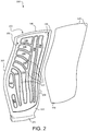
- FIG. 2 a partially exploded view of an airfoil 100 having an airfoil body 110 and a cover 120 is provided.
- the cover 120 is shown removed a distance from the airfoil body 110 because, according to various embodiments, the present disclosure provides structure and methods for attaching the cover 120 to the airfoil body 110.
- Conventional techniques for attaching a cover to an airfoil include stir welding multi-piece covers to an airfoil body and brazing a cover to the an airfoil body.
- the present disclosure provides an airfoil 100 having one or more studs 130 (see, e.g., FIG.
- the airfoil 100 may have improved structural properties. Moreover, the airfoil may be subjected to lower temperatures during manufacture than would otherwise be possible using conventional techniques.
- the airfoil body 110 has a pressure side 101, a suction side 102, a leading edge 103, and a trailing edge 104.
- the airfoil 100 also includes a base 105 and a tip 106 (the base 105 may also be referred to as a "root” or a "blade root”).
- the airfoil 100 may be, for example, a fan blade of the fan section 22 and the fan section 22 may include a plurality of fan blades having the features disclosed herein.
- the airfoil 100 disclosed herein may be utilized in a variety of industries/applications and may have a variety of sizes, shapes, and geometries. Accordingly, the airfoil 100 of the present disclosure is not limited to gas turbine engines and is not limited to the specific geometry, size, and shape shown in the figures.
- the airfoil body 110 may define one or more recesses 108 or cavities that are formed in the suction side 102 and/or the pressure side 101 of the airfoil 100. Therefore, in various embodiments, the airfoil 100 is referred to as "hollow” because it has one or more recesses, cavities, or chambers. These recesses 108 can reduce a weight of the airfoil and can enable the airfoil 100 to be tuned, for example, to improve the rotational dynamics the airfoil 100. In various embodiments, various inserts or filler material may be positioned within the recesses 108 of the airfoil, such as a foam material.
- the airfoil body 110 includes one or more ribs 107 extending through the recess to divide the recess into pockets or subsections of the recess (said differently, the ribs 107 may be portions of the airfoil body 110 that extend between separate recesses 108).
- the cover 120 is disposed on at least one of the suction side 102 and the pressure side 101 and extends across or over the recesses 108. Said differently, the cover 120 may be positioned so as to extend across an opening of the recess(es)108.
- the airfoil body 110 has an indentation 109 and the cover 120 may be designed to fit within the indentation 109.
- an outer periphery 129 of the cover 120 may match the shape of the indentation 109 and thus the cover 120 may be configured to be seated within the indentation 109 to improve the aerodynamics of the airfoil 100 (i.e., avoiding abrupt aerodynamic steps or protrusions that would potentially negatively impact the operation of the airfoil 100).
- the cover 120 may be attached to the airfoil body 110 using one or more studs 130. That is, for example, a first stud and a second stud (e.g., a plurality of studs 130) may extend through the cover 120 and into the airfoil body 110 to retain the cover 120 engaged with the airfoil body 110 by a friction weld. Said differently, a stud 130 may be joined to the airfoil body 110 by a friction weld and the stud 130 may also be joined to the cover 120 by a friction weld, thereby attaching the cover 120 to the airfoil body 110 of the airfoil 100.
- a first stud and a second stud e.g., a plurality of studs 130
- a method 590 of manufacturing the airfoil 100 includes forming a first bore 112 in the airfoil body 110 at step 592, according to various embodiments.
- the method 590 may further include forming a second bore 122 in the cover 120 at step 594.
- the method 590 may include positioning the cover 120 adjacent the airfoil body 110 at step 596.
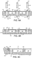
- Step 596 includes positioning the cover 120 so that a first bore axis of the first bore 112 and a second bore axis of the second bore 122 are collinear (the collinearity of the first bore axis and the second bore axis is shown using a single axis, 115, with reference to FIG. 4A ).
- the method 590 may include rotatably forcing a stud 130 into the second bore 122 and into the first bore 112 at step 598.
- step 598 may include friction welding the cover 120 to the stud 130 and friction welding the airfoil body 110 to the stud 130, as described in greater detail below.
- Friction welding is a solid-state welding process that produces heat via mechanical friction between, for example, the stud 130 and the airfoil body 110 and between the stud 130 and the cover 120. Accordingly, joining the airfoil body 110, the cover 120, and the stud 130 together via step 598 of the method 590 includes creating relative rotation between the stud 130 and the combination of the airfoil body 110 and the cover 120. Said differently, step 598 of rotatably forcing the stud 130 into bores/holes formed in the cover 120 and the airfoil body 110 may be achieved by rotating the stud 130 while the airfoil body 110 and the cover 120 remain stationary, or vice versa. In various embodiments, both the stud 130 and the combination of the airfoil body 110 and the cover 120 may be rotating in opposing directions as the stud 130 is inserted through the cover 120 and into the airfoil body 110.
- one or more of the bores 112A formed in the airfoil body 110 is cylindrical and the corresponding stud 130A is also cylindrical.
- one or more of the bores 112B may be a partial bore that does not extend completely through the airfoil body 110.
- the partial bore 112B may have a closed end 113B that is rounded (e.g., spherical, having a radius of curvature) and the corresponding stud 130B may have a rounded tip that corresponds with the rounded closed end 113B.
- the rounded, curved configuration of the stud 130B can reduce stress concentrations that may arise from sharp or abrupt edges.
- one or more of the bores 112C may be tapered and the corresponding stud 130C may also be tapered.
- a tapered stud 130C may be easier to insert and easier to weld, and there may be an increased surface weld area with the tapered bore 112C and tapered stud 130C configuration. Accordingly, the bores 112 and the studs 130 may have various shapes and configurations.
- the first bore 112 has a first diameter 114 and the second bore 122 has a second diameter 124 that are both equal to or smaller than a third diameter 134 of the stud 130 before the stud 130 is rotatably inserted (step 598) through the aligned bores 112, 122.
- the third diameter 134 of the stud 130 is the diameter of the stud 130 pre-insertion (i.e., before step 598), and the third diameter 134 is equal to or greater than the first diameter 114 and the second diameter 124, according to various embodiments.
- the first diameter 114 is substantially the same as the second diameter 124.
- the bore may be a tapered bore 112C and the stud may be a tapered stud 130C.
- the diameter comparison i.e., the comparison of the diameter of the bore with the pre-insertion diameter of the stud
- the diameter comparison is also applicable to tapered bores and tapered studs. That is, the inner diameter profile dimensions of the tapered bore 112C, as a function of location along the bore axis, are less than the pre-inserted, outer diameter profile dimensions of the tapered stud 130C as a function of location along the bore axis.
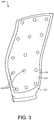
- the one or more studs 130 may be distributed across the pressure side 101 or the suction side 102 of the airfoil 100 (see, for example, FIG. 3 ).
- the stud(s) 130 extend completely through the cover 120 and completely through the airfoil body 110 (e.g., the first bore 112 may be a pass-through bore).
- the stud 130 may extend from the pressure side 101 of the airfoil 100 to the suction side 102 of the airfoil.
- the stud 130 extends only partially through the airfoil body 110, as mentioned above with reference to FIG. 4D .
- the stud 130 extends into/through the ribs 107 of the airfoil body 110 and/or edge portions of the airfoil body 110.
- the one or more ribs 107 of the airfoil body 110 may be designed to have larger dimensions (e.g., at least larger than the first diameter 114 of the first bore 112) at the locations where the stud 130 is configured to be rotatably inserted, thereby enabling the stud 130 to adequately friction weld with the airfoil body 110.
- the exclusive structural connection between the airfoil body 110 and the cover 120 is via the friction weld of the stud(s) 130.
- the method 590 of manufacturing may include additional joining steps, such as applying a braze filler material 140 between respective mating surfaces of the cover 120 and the airfoil body 110 and heating the braze filler material to seal braze the cover 120 to the airfoil body 110, these additional joining techniques may not substantially contribute to the overall structural strength of the airfoil 100 (e.g., the friction weld of the stud(s) 130 exclusively structurally holds the airfoil 100 together, but the braze filler material 140 may minimize high residual stress concentrations that would otherwise occur between the respective mating surfaces of the cover 120 and the ribs 107 and peripheral recesses of the airfoil body 110).
- the brazing process may be performed under vacuum. In various embodiments, the brazing process is performed in an inert gas environment.
- the method 590 may further include applying a protective filler material 150 in a seam 118 (also shown in FIG. 3 ) between the cover 120 and the airfoil body 110 (e.g., between the outer periphery 129 of the cover 120 and side walls of the indentation 119 described above with reference to FIG. 2 ). Applying the protective filler material may be performed after friction welding (e.g., step 598) and after the optional step of applying and heating the braze filler material 140.
- the protective filler material 150 includes an anti-corrosion compound, an anti-erosion compound, or a combination of the two.
- the anti-erosion compound may include a corrosion inhibiting paint, such as a compound including zinc molybdate, and the anti-erosion compound may include a polyurethane compound.
- applying the protective filler material 150 may include applying an anti-corrosion compound in the seam 118, subsequently curing the anti-corrosion compound, and then subsequently applying an anti-corrosion compound over the cured anti-corrosion compound.
- the airfoil body 110, the cover 120, and the stud(s) 130 may be formed of various materials and by various manufacturing processes.
- the airfoil body 110, with its defined recesses 108 may be cast, machined from wrought product, or produced via additive manufacturing.
- the bores 112, 122 may be formed during casting or may be subsequently formed via drilling, milling, or other suitable techniques.
- the airfoil body 110, the cover 120, and the stud 130 may be made from similar materials.
- the airfoil body 110, the cover 120, and the stud 130 may be made from the same metal or at least from alloys of the same metal, according to various embodiments.
- the airfoil body 110, the cover 120, and the stud 130 may be made from aluminum, aluminum alloys, titanium, titanium alloys, or other suitable materials.
- any of the method or process descriptions may be executed in any order and are not necessarily limited to the order presented.
- any reference to singular includes plural embodiments, and any reference to more than one component or step may include a singular embodiment or step.
- Elements and steps in the figures are illustrated for simplicity and clarity and have not necessarily been rendered according to any particular sequence. For example, steps that may be performed concurrently or in different order are illustrated in the figures to help to improve understanding of embodiments of the present disclosure.
- Any reference to attached, fixed, connected or the like may include permanent, removable, temporary, partial, full and/or any other possible attachment option. Additionally, any reference to without contact (or similar phrases) may also include reduced contact or minimal contact. Surface shading lines may be used throughout the figures to denote different parts or areas but not necessarily to denote the same or different materials. In some cases, reference coordinates may be specific to each figure.
- references to "one embodiment”, “an embodiment”, “various embodiments”, etc. indicate that the embodiment described may include a particular feature, structure, or characteristic, but every embodiment may not necessarily include the particular feature, structure, or characteristic. Moreover, such phrases are not necessarily referring to the same embodiment. Further, when a particular feature, structure, or characteristic is described in connection with an embodiment, it is submitted that it is within the knowledge of one skilled in the art to affect such feature, structure, or characteristic in connection with other embodiments whether or not explicitly described. After reading the description, it will be apparent to one skilled in the relevant art(s) how to implement the disclosure in alternative embodiments.
Landscapes
- Engineering & Computer Science (AREA)
- Mechanical Engineering (AREA)
- Architecture (AREA)
- General Engineering & Computer Science (AREA)
- Structures Of Non-Positive Displacement Pumps (AREA)
Applications Claiming Priority (1)
| Application Number | Priority Date | Filing Date | Title |
|---|---|---|---|
| US15/482,540 US10329919B2 (en) | 2017-04-07 | 2017-04-07 | Airfoil structure and method of manufacture |
Publications (2)
| Publication Number | Publication Date |
|---|---|
| EP3385026A1 true EP3385026A1 (fr) | 2018-10-10 |
| EP3385026B1 EP3385026B1 (fr) | 2020-09-23 |
Family
ID=61683635
Family Applications (1)
| Application Number | Title | Priority Date | Filing Date |
|---|---|---|---|
| EP18161954.5A Active EP3385026B1 (fr) | 2017-04-07 | 2018-03-15 | Structure de surface portante et procédé de fabrication |
Country Status (2)
| Country | Link |
|---|---|
| US (1) | US10329919B2 (fr) |
| EP (1) | EP3385026B1 (fr) |
Cited By (2)
| Publication number | Priority date | Publication date | Assignee | Title |
|---|---|---|---|---|
| DE102018217501A1 (de) * | 2018-10-12 | 2020-04-16 | Siemens Aktiengesellschaft | Verfahren zum Fügen einer modular aufgebauten Heißgaskomponente mittels Schweißen und Hochtemperaturlöten und Komponente |
| EP3712377A1 (fr) * | 2019-03-20 | 2020-09-23 | United Technologies Corporation | Procédé de formation de composants de moteur à turbine à gaz |
Families Citing this family (6)
| Publication number | Priority date | Publication date | Assignee | Title |
|---|---|---|---|---|
| US10828718B2 (en) * | 2018-06-14 | 2020-11-10 | Raytheon Technologies Corporation | Installation of waterjet vent holes into vertical walls of cavity-back airfoils |
| US10919116B2 (en) | 2018-06-14 | 2021-02-16 | Raytheon Technologies Corporation | Installation of laser vent holes into vertical walls of cavity-back airfoils |
| US11236619B2 (en) * | 2019-05-07 | 2022-02-01 | Raytheon Technologies Corporation | Multi-cover gas turbine engine component |
| US20240309764A1 (en) * | 2023-03-14 | 2024-09-19 | Raytheon Technologies Corporation | Altering structural response of two-piece hollow-vane assembly |
| US12571329B2 (en) * | 2023-03-14 | 2026-03-10 | Rtx Corporation | Altering structural response of two-piece hollow-vane assembly |
| EP4477840A1 (fr) * | 2023-06-13 | 2024-12-18 | RTX Corporation | Pale de soufflante creuse en aluminium renforcée par un adhésif pour la rétention de couvercle collé |
Citations (4)
| Publication number | Priority date | Publication date | Assignee | Title |
|---|---|---|---|---|
| US3402914A (en) * | 1965-02-10 | 1968-09-24 | Curtiss Wright Corp | Method of controlling the permeability of a porous material, and turbine blade formed thereby |
| JP2003266184A (ja) * | 2002-03-15 | 2003-09-24 | Shin Meiwa Ind Co Ltd | 中空の組立構造物及び航空機の動翼 |
| US20040232209A1 (en) * | 2000-12-20 | 2004-11-25 | Israel Stol | Friction plunge riveting process |
| US20120201653A1 (en) * | 2010-12-30 | 2012-08-09 | Corina Moga | Gas turbine engine and cooled flowpath component therefor |
Family Cites Families (11)
| Publication number | Priority date | Publication date | Assignee | Title |
|---|---|---|---|---|
| US3096826A (en) * | 1961-08-07 | 1963-07-09 | Hughes Tool Co | Rotor blade for rotary-winged aircraft |
| US5248241A (en) * | 1991-10-21 | 1993-09-28 | Southern California Edison Co. | Components made of hardenable and non-hardenable materials |
| DE19542080C1 (de) | 1995-11-11 | 1997-01-30 | Mtu Muenchen Gmbh | Schaufelblatt für Turbotriebwerke zur Herstellung von Laufrädern mit integralen Hohlschaufeln |
| US7189064B2 (en) * | 2004-05-14 | 2007-03-13 | General Electric Company | Friction stir welded hollow airfoils and method therefor |
| US7789621B2 (en) * | 2005-06-27 | 2010-09-07 | Rolls-Royce North American Technologies, Inc. | Gas turbine engine airfoil |
| US20090280252A1 (en) * | 2008-05-06 | 2009-11-12 | Andrew Armstrong | Method for Extending and Improving the Functionality of a Hard Surface |
| US9221120B2 (en) * | 2012-01-04 | 2015-12-29 | United Technologies Corporation | Aluminum fan blade construction with welded cover |
| US9233414B2 (en) | 2012-01-31 | 2016-01-12 | United Technologies Corporation | Aluminum airfoil |
| US20140241897A1 (en) | 2012-09-25 | 2014-08-28 | United Technologies Corporation | Aluminum brazing of hollow titanium fan blades |
| ITTV20120204A1 (it) | 2012-10-30 | 2014-05-01 | Pietro Rosa T B M S R L | Metodo di costruzione di una paletta alleggerita per turbomacchine |
| EP3084135B1 (fr) | 2013-12-16 | 2019-02-06 | United Technologies Corporation | Pale de ventilateur creuse muni d'un support d'élément couvrant soudé sous agitation |
-
2017
- 2017-04-07 US US15/482,540 patent/US10329919B2/en active Active
-
2018
- 2018-03-15 EP EP18161954.5A patent/EP3385026B1/fr active Active
Patent Citations (4)
| Publication number | Priority date | Publication date | Assignee | Title |
|---|---|---|---|---|
| US3402914A (en) * | 1965-02-10 | 1968-09-24 | Curtiss Wright Corp | Method of controlling the permeability of a porous material, and turbine blade formed thereby |
| US20040232209A1 (en) * | 2000-12-20 | 2004-11-25 | Israel Stol | Friction plunge riveting process |
| JP2003266184A (ja) * | 2002-03-15 | 2003-09-24 | Shin Meiwa Ind Co Ltd | 中空の組立構造物及び航空機の動翼 |
| US20120201653A1 (en) * | 2010-12-30 | 2012-08-09 | Corina Moga | Gas turbine engine and cooled flowpath component therefor |
Cited By (5)
| Publication number | Priority date | Publication date | Assignee | Title |
|---|---|---|---|---|
| DE102018217501A1 (de) * | 2018-10-12 | 2020-04-16 | Siemens Aktiengesellschaft | Verfahren zum Fügen einer modular aufgebauten Heißgaskomponente mittels Schweißen und Hochtemperaturlöten und Komponente |
| US11504807B2 (en) | 2018-10-12 | 2022-11-22 | Siemens Energy Global GmbH & Co. KG | Method for joining a modular hot gas component using welding and high-temperature soldering, and joined component |
| EP3712377A1 (fr) * | 2019-03-20 | 2020-09-23 | United Technologies Corporation | Procédé de formation de composants de moteur à turbine à gaz |
| US11033993B2 (en) | 2019-03-20 | 2021-06-15 | Raytheon Technologies Corporation | Method of forming gas turbine engine components |
| EP4234884A3 (fr) * | 2019-03-20 | 2023-12-06 | RTX Corporation | Procédé de formation de composants de moteur à turbine à gaz |
Also Published As
| Publication number | Publication date |
|---|---|
| US20180291746A1 (en) | 2018-10-11 |
| EP3385026B1 (fr) | 2020-09-23 |
| US10329919B2 (en) | 2019-06-25 |
Similar Documents
| Publication | Publication Date | Title |
|---|---|---|
| EP3385026B1 (fr) | Structure de surface portante et procédé de fabrication | |
| EP3783196B1 (fr) | Profil aérodynamique hybride pour un moteur à turbine à gaz | |
| JP6255051B2 (ja) | ガスタービンエンジンの隣接ノズルを配置するための方法 | |
| US9394915B2 (en) | Seal land for static structure of a gas turbine engine | |
| EP3477058B1 (fr) | Circuit de refroidissement de profil aérodynamique | |
| EP3252271B1 (fr) | Ensemble pour aube, étage de soufflante et moteur à turbine à gaz associés | |
| JP2016205390A5 (fr) | ||
| EP3421723A2 (fr) | Profilé d'aube et procédé associé de fabrication | |
| EP3109405A1 (fr) | Tours en serpentin à chicanes à faible perte | |
| EP3081762B1 (fr) | Joint à brosse axiale statique à double pinceaux | |
| EP3379032B1 (fr) | Aube refroidie et moteur à turbine à gaz associé | |
| US20170328224A1 (en) | Contoured retaining ring | |
| EP3263841B1 (fr) | Bossage de carter de turbine | |
| US9957820B2 (en) | Heat shield for a vane assembly of a gas turbine engine | |
| US20190309643A1 (en) | Axial stiffening ribs/augmentation fins | |
| EP3477053B1 (fr) | Circuit de refroidissement de profil aérodynamique d'une turbine á gaz et procédé de fabrication | |
| EP4088836B1 (fr) | Pare-chocs centraux intégrés | |
| US9976427B2 (en) | Installation fault tolerant damper | |
| US9926789B2 (en) | Flow splitting baffle | |
| EP3425167B1 (fr) | Machines rotatives comprenant un rotor hybride ayant des ensembles d' aubes de rotor creuses et pleines | |
| US10822959B2 (en) | Blade tip cooling | |
| EP3437792A1 (fr) | Procédé de fabrication d'une aube de turbine |
Legal Events
| Date | Code | Title | Description |
|---|---|---|---|
| PUAI | Public reference made under article 153(3) epc to a published international application that has entered the european phase |
Free format text: ORIGINAL CODE: 0009012 |
|
| STAA | Information on the status of an ep patent application or granted ep patent |
Free format text: STATUS: THE APPLICATION HAS BEEN PUBLISHED |
|
| AK | Designated contracting states |
Kind code of ref document: A1 Designated state(s): AL AT BE BG CH CY CZ DE DK EE ES FI FR GB GR HR HU IE IS IT LI LT LU LV MC MK MT NL NO PL PT RO RS SE SI SK SM TR |
|
| AX | Request for extension of the european patent |
Extension state: BA ME |
|
| STAA | Information on the status of an ep patent application or granted ep patent |
Free format text: STATUS: REQUEST FOR EXAMINATION WAS MADE |
|
| 17P | Request for examination filed |
Effective date: 20190410 |
|
| RBV | Designated contracting states (corrected) |
Designated state(s): AL AT BE BG CH CY CZ DE DK EE ES FI FR GB GR HR HU IE IS IT LI LT LU LV MC MK MT NL NO PL PT RO RS SE SI SK SM TR |
|
| RIC1 | Information provided on ipc code assigned before grant |
Ipc: B23K 103/10 20060101ALN20190904BHEP Ipc: B23K 103/18 20060101ALN20190904BHEP Ipc: B23K 101/00 20060101ALN20190904BHEP Ipc: B23K 103/14 20060101ALN20190904BHEP Ipc: B21J 15/02 20060101ALI20190904BHEP Ipc: B23K 20/233 20060101ALI20190904BHEP Ipc: B23K 20/12 20060101AFI20190904BHEP Ipc: F01D 5/14 20060101ALI20190904BHEP |
|
| GRAP | Despatch of communication of intention to grant a patent |
Free format text: ORIGINAL CODE: EPIDOSNIGR1 |
|
| STAA | Information on the status of an ep patent application or granted ep patent |
Free format text: STATUS: GRANT OF PATENT IS INTENDED |
|
| RIC1 | Information provided on ipc code assigned before grant |
Ipc: B23K 103/14 20060101ALN20190909BHEP Ipc: F01D 5/14 20060101ALI20190909BHEP Ipc: B23K 103/18 20060101ALN20190909BHEP Ipc: B23K 20/233 20060101ALI20190909BHEP Ipc: B23K 101/00 20060101ALN20190909BHEP Ipc: B23K 20/12 20060101AFI20190909BHEP Ipc: B21J 15/02 20060101ALI20190909BHEP Ipc: B23K 103/10 20060101ALN20190909BHEP |
|
| INTG | Intention to grant announced |
Effective date: 20191011 |
|
| GRAJ | Information related to disapproval of communication of intention to grant by the applicant or resumption of examination proceedings by the epo deleted |
Free format text: ORIGINAL CODE: EPIDOSDIGR1 |
|
| STAA | Information on the status of an ep patent application or granted ep patent |
Free format text: STATUS: REQUEST FOR EXAMINATION WAS MADE |
|
| INTC | Intention to grant announced (deleted) | ||
| RIC1 | Information provided on ipc code assigned before grant |
Ipc: B21J 15/02 20060101ALI20200302BHEP Ipc: B23K 101/00 20060101ALN20200302BHEP Ipc: B23K 20/233 20060101ALI20200302BHEP Ipc: F01D 5/14 20060101ALI20200302BHEP Ipc: B23K 103/18 20060101ALN20200302BHEP Ipc: B23K 103/14 20060101ALN20200302BHEP Ipc: B23K 103/10 20060101ALN20200302BHEP Ipc: B23K 20/12 20060101AFI20200302BHEP |
|
| GRAP | Despatch of communication of intention to grant a patent |
Free format text: ORIGINAL CODE: EPIDOSNIGR1 |
|
| STAA | Information on the status of an ep patent application or granted ep patent |
Free format text: STATUS: GRANT OF PATENT IS INTENDED |
|
| INTG | Intention to grant announced |
Effective date: 20200512 |
|
| GRAS | Grant fee paid |
Free format text: ORIGINAL CODE: EPIDOSNIGR3 |
|
| GRAA | (expected) grant |
Free format text: ORIGINAL CODE: 0009210 |
|
| STAA | Information on the status of an ep patent application or granted ep patent |
Free format text: STATUS: THE PATENT HAS BEEN GRANTED |
|
| AK | Designated contracting states |
Kind code of ref document: B1 Designated state(s): AL AT BE BG CH CY CZ DE DK EE ES FI FR GB GR HR HU IE IS IT LI LT LU LV MC MK MT NL NO PL PT RO RS SE SI SK SM TR |
|
| REG | Reference to a national code |
Ref country code: GB Ref legal event code: FG4D |
|
| REG | Reference to a national code |
Ref country code: CH Ref legal event code: EP |
|
| REG | Reference to a national code |
Ref country code: IE Ref legal event code: FG4D |
|
| REG | Reference to a national code |
Ref country code: DE Ref legal event code: R096 Ref document number: 602018007971 Country of ref document: DE Ref country code: AT Ref legal event code: REF Ref document number: 1315892 Country of ref document: AT Kind code of ref document: T Effective date: 20201015 |
|
| PG25 | Lapsed in a contracting state [announced via postgrant information from national office to epo] |
Ref country code: NO Free format text: LAPSE BECAUSE OF FAILURE TO SUBMIT A TRANSLATION OF THE DESCRIPTION OR TO PAY THE FEE WITHIN THE PRESCRIBED TIME-LIMIT Effective date: 20201223 Ref country code: GR Free format text: LAPSE BECAUSE OF FAILURE TO SUBMIT A TRANSLATION OF THE DESCRIPTION OR TO PAY THE FEE WITHIN THE PRESCRIBED TIME-LIMIT Effective date: 20201224 Ref country code: SE Free format text: LAPSE BECAUSE OF FAILURE TO SUBMIT A TRANSLATION OF THE DESCRIPTION OR TO PAY THE FEE WITHIN THE PRESCRIBED TIME-LIMIT Effective date: 20200923 Ref country code: HR Free format text: LAPSE BECAUSE OF FAILURE TO SUBMIT A TRANSLATION OF THE DESCRIPTION OR TO PAY THE FEE WITHIN THE PRESCRIBED TIME-LIMIT Effective date: 20200923 Ref country code: FI Free format text: LAPSE BECAUSE OF FAILURE TO SUBMIT A TRANSLATION OF THE DESCRIPTION OR TO PAY THE FEE WITHIN THE PRESCRIBED TIME-LIMIT Effective date: 20200923 Ref country code: BG Free format text: LAPSE BECAUSE OF FAILURE TO SUBMIT A TRANSLATION OF THE DESCRIPTION OR TO PAY THE FEE WITHIN THE PRESCRIBED TIME-LIMIT Effective date: 20201223 |
|
| REG | Reference to a national code |
Ref country code: AT Ref legal event code: MK05 Ref document number: 1315892 Country of ref document: AT Kind code of ref document: T Effective date: 20200923 |
|
| PG25 | Lapsed in a contracting state [announced via postgrant information from national office to epo] |
Ref country code: RS Free format text: LAPSE BECAUSE OF FAILURE TO SUBMIT A TRANSLATION OF THE DESCRIPTION OR TO PAY THE FEE WITHIN THE PRESCRIBED TIME-LIMIT Effective date: 20200923 Ref country code: LV Free format text: LAPSE BECAUSE OF FAILURE TO SUBMIT A TRANSLATION OF THE DESCRIPTION OR TO PAY THE FEE WITHIN THE PRESCRIBED TIME-LIMIT Effective date: 20200923 |
|
| REG | Reference to a national code |
Ref country code: NL Ref legal event code: MP Effective date: 20200923 |
|
| RAP2 | Party data changed (patent owner data changed or rights of a patent transferred) |
Owner name: RAYTHEON TECHNOLOGIES CORPORATION |
|
| REG | Reference to a national code |
Ref country code: LT Ref legal event code: MG4D |
|
| PG25 | Lapsed in a contracting state [announced via postgrant information from national office to epo] |
Ref country code: EE Free format text: LAPSE BECAUSE OF FAILURE TO SUBMIT A TRANSLATION OF THE DESCRIPTION OR TO PAY THE FEE WITHIN THE PRESCRIBED TIME-LIMIT Effective date: 20200923 Ref country code: RO Free format text: LAPSE BECAUSE OF FAILURE TO SUBMIT A TRANSLATION OF THE DESCRIPTION OR TO PAY THE FEE WITHIN THE PRESCRIBED TIME-LIMIT Effective date: 20200923 Ref country code: PT Free format text: LAPSE BECAUSE OF FAILURE TO SUBMIT A TRANSLATION OF THE DESCRIPTION OR TO PAY THE FEE WITHIN THE PRESCRIBED TIME-LIMIT Effective date: 20210125 Ref country code: CZ Free format text: LAPSE BECAUSE OF FAILURE TO SUBMIT A TRANSLATION OF THE DESCRIPTION OR TO PAY THE FEE WITHIN THE PRESCRIBED TIME-LIMIT Effective date: 20200923 Ref country code: LT Free format text: LAPSE BECAUSE OF FAILURE TO SUBMIT A TRANSLATION OF THE DESCRIPTION OR TO PAY THE FEE WITHIN THE PRESCRIBED TIME-LIMIT Effective date: 20200923 Ref country code: SM Free format text: LAPSE BECAUSE OF FAILURE TO SUBMIT A TRANSLATION OF THE DESCRIPTION OR TO PAY THE FEE WITHIN THE PRESCRIBED TIME-LIMIT Effective date: 20200923 |
|
| PG25 | Lapsed in a contracting state [announced via postgrant information from national office to epo] |
Ref country code: AL Free format text: LAPSE BECAUSE OF FAILURE TO SUBMIT A TRANSLATION OF THE DESCRIPTION OR TO PAY THE FEE WITHIN THE PRESCRIBED TIME-LIMIT Effective date: 20200923 Ref country code: AT Free format text: LAPSE BECAUSE OF FAILURE TO SUBMIT A TRANSLATION OF THE DESCRIPTION OR TO PAY THE FEE WITHIN THE PRESCRIBED TIME-LIMIT Effective date: 20200923 Ref country code: ES Free format text: LAPSE BECAUSE OF FAILURE TO SUBMIT A TRANSLATION OF THE DESCRIPTION OR TO PAY THE FEE WITHIN THE PRESCRIBED TIME-LIMIT Effective date: 20200923 Ref country code: IS Free format text: LAPSE BECAUSE OF FAILURE TO SUBMIT A TRANSLATION OF THE DESCRIPTION OR TO PAY THE FEE WITHIN THE PRESCRIBED TIME-LIMIT Effective date: 20210123 Ref country code: PL Free format text: LAPSE BECAUSE OF FAILURE TO SUBMIT A TRANSLATION OF THE DESCRIPTION OR TO PAY THE FEE WITHIN THE PRESCRIBED TIME-LIMIT Effective date: 20200923 |
|
| REG | Reference to a national code |
Ref country code: DE Ref legal event code: R097 Ref document number: 602018007971 Country of ref document: DE |
|
| PG25 | Lapsed in a contracting state [announced via postgrant information from national office to epo] |
Ref country code: SK Free format text: LAPSE BECAUSE OF FAILURE TO SUBMIT A TRANSLATION OF THE DESCRIPTION OR TO PAY THE FEE WITHIN THE PRESCRIBED TIME-LIMIT Effective date: 20200923 |
|
| PLBE | No opposition filed within time limit |
Free format text: ORIGINAL CODE: 0009261 |
|
| STAA | Information on the status of an ep patent application or granted ep patent |
Free format text: STATUS: NO OPPOSITION FILED WITHIN TIME LIMIT |
|
| PG25 | Lapsed in a contracting state [announced via postgrant information from national office to epo] |
Ref country code: SI Free format text: LAPSE BECAUSE OF FAILURE TO SUBMIT A TRANSLATION OF THE DESCRIPTION OR TO PAY THE FEE WITHIN THE PRESCRIBED TIME-LIMIT Effective date: 20200923 Ref country code: DK Free format text: LAPSE BECAUSE OF FAILURE TO SUBMIT A TRANSLATION OF THE DESCRIPTION OR TO PAY THE FEE WITHIN THE PRESCRIBED TIME-LIMIT Effective date: 20200923 |
|
| 26N | No opposition filed |
Effective date: 20210624 |
|
| PG25 | Lapsed in a contracting state [announced via postgrant information from national office to epo] |
Ref country code: MC Free format text: LAPSE BECAUSE OF FAILURE TO SUBMIT A TRANSLATION OF THE DESCRIPTION OR TO PAY THE FEE WITHIN THE PRESCRIBED TIME-LIMIT Effective date: 20200923 Ref country code: IT Free format text: LAPSE BECAUSE OF FAILURE TO SUBMIT A TRANSLATION OF THE DESCRIPTION OR TO PAY THE FEE WITHIN THE PRESCRIBED TIME-LIMIT Effective date: 20200923 |
|
| REG | Reference to a national code |
Ref country code: CH Ref legal event code: PL |
|
| REG | Reference to a national code |
Ref country code: BE Ref legal event code: MM Effective date: 20210331 |
|
| PG25 | Lapsed in a contracting state [announced via postgrant information from national office to epo] |
Ref country code: IE Free format text: LAPSE BECAUSE OF NON-PAYMENT OF DUE FEES Effective date: 20210315 Ref country code: LU Free format text: LAPSE BECAUSE OF NON-PAYMENT OF DUE FEES Effective date: 20210315 Ref country code: LI Free format text: LAPSE BECAUSE OF NON-PAYMENT OF DUE FEES Effective date: 20210331 Ref country code: CH Free format text: LAPSE BECAUSE OF NON-PAYMENT OF DUE FEES Effective date: 20210331 |
|
| PG25 | Lapsed in a contracting state [announced via postgrant information from national office to epo] |
Ref country code: BE Free format text: LAPSE BECAUSE OF NON-PAYMENT OF DUE FEES Effective date: 20210331 |
|
| P01 | Opt-out of the competence of the unified patent court (upc) registered |
Effective date: 20230521 |
|
| PG25 | Lapsed in a contracting state [announced via postgrant information from national office to epo] |
Ref country code: NL Free format text: LAPSE BECAUSE OF NON-PAYMENT OF DUE FEES Effective date: 20200923 Ref country code: CY Free format text: LAPSE BECAUSE OF FAILURE TO SUBMIT A TRANSLATION OF THE DESCRIPTION OR TO PAY THE FEE WITHIN THE PRESCRIBED TIME-LIMIT Effective date: 20200923 |
|
| PG25 | Lapsed in a contracting state [announced via postgrant information from national office to epo] |
Ref country code: HU Free format text: LAPSE BECAUSE OF FAILURE TO SUBMIT A TRANSLATION OF THE DESCRIPTION OR TO PAY THE FEE WITHIN THE PRESCRIBED TIME-LIMIT; INVALID AB INITIO Effective date: 20180315 |
|
| PG25 | Lapsed in a contracting state [announced via postgrant information from national office to epo] |
Ref country code: MK Free format text: LAPSE BECAUSE OF FAILURE TO SUBMIT A TRANSLATION OF THE DESCRIPTION OR TO PAY THE FEE WITHIN THE PRESCRIBED TIME-LIMIT Effective date: 20200923 |
|
| PG25 | Lapsed in a contracting state [announced via postgrant information from national office to epo] |
Ref country code: MT Free format text: LAPSE BECAUSE OF FAILURE TO SUBMIT A TRANSLATION OF THE DESCRIPTION OR TO PAY THE FEE WITHIN THE PRESCRIBED TIME-LIMIT Effective date: 20200923 |
|
| REG | Reference to a national code |
Ref country code: DE Ref legal event code: R081 Ref document number: 602018007971 Country of ref document: DE Owner name: RTX CORPORATION (N.D.GES.D. STAATES DELAWARE),, US Free format text: FORMER OWNER: UNITED TECHNOLOGIES CORPORATION, FARMINGTON, CONN., US |
|
| PG25 | Lapsed in a contracting state [announced via postgrant information from national office to epo] |
Ref country code: TR Free format text: LAPSE BECAUSE OF FAILURE TO SUBMIT A TRANSLATION OF THE DESCRIPTION OR TO PAY THE FEE WITHIN THE PRESCRIBED TIME-LIMIT Effective date: 20200923 |
|
| PGFP | Annual fee paid to national office [announced via postgrant information from national office to epo] |
Ref country code: GB Payment date: 20260220 Year of fee payment: 9 |
|
| PGFP | Annual fee paid to national office [announced via postgrant information from national office to epo] |
Ref country code: DE Payment date: 20260219 Year of fee payment: 9 |
|
| PGFP | Annual fee paid to national office [announced via postgrant information from national office to epo] |
Ref country code: FR Payment date: 20260220 Year of fee payment: 9 |