EP3385033B1 - Dispositif de déverrouillage de fixations de tuyau - Google Patents
Dispositif de déverrouillage de fixations de tuyau Download PDFInfo
- Publication number
- EP3385033B1 EP3385033B1 EP18153251.6A EP18153251A EP3385033B1 EP 3385033 B1 EP3385033 B1 EP 3385033B1 EP 18153251 A EP18153251 A EP 18153251A EP 3385033 B1 EP3385033 B1 EP 3385033B1
- Authority
- EP
- European Patent Office
- Prior art keywords
- extension
- cable
- section
- segment
- extends
- Prior art date
- Legal status (The legal status is an assumption and is not a legal conclusion. Google has not performed a legal analysis and makes no representation as to the accuracy of the status listed.)
- Active
Links
Images







Classifications
-
- B—PERFORMING OPERATIONS; TRANSPORTING
- B25—HAND TOOLS; PORTABLE POWER-DRIVEN TOOLS; MANIPULATORS
- B25B—TOOLS OR BENCH DEVICES NOT OTHERWISE PROVIDED FOR, FOR FASTENING, CONNECTING, DISENGAGING, OR HOLDING
- B25B25/00—Implements for fastening, connecting or tensioning of wire or strip
- B25B25/005—Implements for fastening, connecting or tensioning of wire or strip for applying wire clasps to hose couplings
-
- B—PERFORMING OPERATIONS; TRANSPORTING
- B25—HAND TOOLS; PORTABLE POWER-DRIVEN TOOLS; MANIPULATORS
- B25B—TOOLS OR BENCH DEVICES NOT OTHERWISE PROVIDED FOR, FOR FASTENING, CONNECTING, DISENGAGING, OR HOLDING
- B25B7/00—Pliers; Other hand-held gripping tools with jaws on pivoted limbs; Details applicable generally to pivoted-limb hand tools
- B25B7/02—Jaws
-
- B—PERFORMING OPERATIONS; TRANSPORTING
- B25—HAND TOOLS; PORTABLE POWER-DRIVEN TOOLS; MANIPULATORS
- B25B—TOOLS OR BENCH DEVICES NOT OTHERWISE PROVIDED FOR, FOR FASTENING, CONNECTING, DISENGAGING, OR HOLDING
- B25B13/00—Spanners; Wrenches
- B25B13/10—Spanners; Wrenches with adjustable jaws
- B25B13/28—Spanners; Wrenches with adjustable jaws the jaws being pivotally movable
-
- B—PERFORMING OPERATIONS; TRANSPORTING
- B25—HAND TOOLS; PORTABLE POWER-DRIVEN TOOLS; MANIPULATORS
- B25B—TOOLS OR BENCH DEVICES NOT OTHERWISE PROVIDED FOR, FOR FASTENING, CONNECTING, DISENGAGING, OR HOLDING
- B25B13/00—Spanners; Wrenches
- B25B13/44—Spanners; Wrenches of the chuck type
-
- B—PERFORMING OPERATIONS; TRANSPORTING
- B25—HAND TOOLS; PORTABLE POWER-DRIVEN TOOLS; MANIPULATORS
- B25B—TOOLS OR BENCH DEVICES NOT OTHERWISE PROVIDED FOR, FOR FASTENING, CONNECTING, DISENGAGING, OR HOLDING
- B25B7/00—Pliers; Other hand-held gripping tools with jaws on pivoted limbs; Details applicable generally to pivoted-limb hand tools
- B25B7/12—Pliers; Other hand-held gripping tools with jaws on pivoted limbs; Details applicable generally to pivoted-limb hand tools involving special transmission means between the handles and the jaws, e.g. toggle levers, gears
Definitions
- the present invention relates to a hand tool, and more particularly to a hand tool for unfastening pipe fasteners in a narrow space such as in an engine room.
- the fasteners When separating the pipes from the connectors, the fasteners are first enlarged and moved along the pipes until the fasteners are moved away from the connectors. The pipes are then pulled away from the connectors.
- the pipes When connecting the pipes to the connectors, the pipes are first mounted to the connectors, and the fasteners on the pipes are then enlarged and moved along the pipes until the fasteners are moved to the connectors. The fasteners are fastened to secure the pipes to the connectors.
- the users use pliers to access the fasteners and enlarge the fasteners.
- the fasteners are not easily accessed because too many parts are located nearby. If the parts near the top of the fasteners are to be removed from the engine room, it will take too much time and obviously is not an efficient task.
- US Patent No. 6,276,236 and US Patent No. 7,104,162 disclose devices for unfastening fasteners.
- the device usually comprises an operation device, a cable unit and a working unit, wherein the cable unit is connected between the operation device and the working unit.
- the cable unit includes a cable and a sheath.
- the operation device pulls the cable relative to the sheath, and the cable drives the working unit.
- US Patent No. 6,370,985 discloses a device for unfastening fasteners according to the preamble of claim 1, comprising:
- the devices disclosed by the above mentioned documents can unfasten or remove the fasteners in a narrow space.
- the present invention has for its object the provision of a device for unfastening pipe fasteners that has increased functionality.
- the stop member includes a board and a flange extending along a portion of a periphery of the board, the board has an aperture defined therethrough, the board is mounted to the first extension, the end piece extends through the aperture and contacts outside of the board, the flange is mounted to a top and two sides of the first extension and closes first slot at the top of the first extension, the board has two arms extending therefrom which position the board therebetween, each arm has a hooked end which hooks an inside of the first extension to secure the first extension to the stop member.
- the flange has a tongue extending therefrom which is engaged with the first slot to prevent the cable from disengaging from the first hole via the first slot.
- the second extension has a housing mounted thereto, the housing includes a space in which a portion of the second extension is accommodated.
- the housing includes a first portion, a second portion and a second connection portion, the first and second portions face each other, the second connection portion is connected between the first and second portions, the first side portion includes a third notch and a third recess defined in an inside thereof, the second portion includes a fourth notch and a fourth recess defined in an inside thereof, the third notch is located corresponding to the fourth notch, the third recess is located corresponding to the fourth recess, the third and fourth notches communicate with a front side of the space, the third and fourth recesses communicate with a rear side of the space, the first segment enters into the space via the third and fourth recesses, and contacts the second extension, the cable extends through the third and fourth recesses, and extends beyond the space, a second transverse portion extends laterally from the second portion and includes a second engaging portion on a distal end thereof which extends toward and contacts outside of the first portion so as to connect the first and second portions.
- the housing includes an outlet, the positioning member formed by bending a metal wire, a top of the positioning member extends through the outlet, the positioning member includes a first section, a second section, a third section, and a fourth section, a first section, the first section is located to face the second section, the first section and the second section are integrally formed with each other at two respective top thereof, two respective lower ends of the first section and the second section are located close to each other, the third section extends from the lower end of the first section at an angle, the fourth section extends from the lower end of the second section at an angle, a distance between the third and fourth sections increases in a direction toward two respective distal ends of the third and fourth sections, a clamp area is formed between the first and second sections, when the second segment enters into the clamp area, the second segment is clamped by the first and second sections.
- the positioning member is a C-clip.
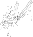
- the device for unfastening pipe fasteners of the present invention comprises an operation device 1, a cable unit 2 and a working unit 3.
- the cable unit 2 is connected between the operation device 1 and the working unit 3.
- the operation device 1 controls the working unit 3 by the cable unit 2.
- the operation device 1 comprises a first part 11, a second part 12 and a pivot 13.
- the first and second parts 11, 12 are pivotably connected to each other at two respective middle portions thereof by the pivot 13.
- the first and second parts 11, 12 are pivotable about the pivot 13.
- a torsion spring 14 is connected between the first and second parts 11, 12 so that when the users release the first and second parts 11, 12, the torsion spring 14 biases the first and second parts 11, 12 back to their initial positions.
- the first part 11 includes a first handle 112 and a first extension 114 respectively formed on two ends thereof
- the second part 12 includes a second handle 122 and a second extension 124 respectively formed on two ends thereof.
- the first extension 114 has a first hole 116
- the second extension 124 has a second hole 126.
- the cable unit 2 includes a cable 21 and a sheath 22 through which the cable 21 extends.
- the first end of the cable 21 extends beyond the first end of the sheath 22 and is connected to the operation device 1.
- the second end of the cable 21 extends beyond a second end of the sheath 22 and is connected to the working unit 3.
- the first end of the cable 21 extends through the second hole 126 and the first hole 116, and is connected to an end piece 23 which contacts against the first extension 114.
- the sheath 22 has the first end thereof connected with an insertion 24 which includes a first segment 242 and a second segment 244 which is axially connected to the first segment 242.
- the first segment 242 is connected to the sheath 22.
- the second segment 244 extends through the second hole 126.
- the outer diameter of the first segment 242 is larger than an inner diameter of the second hole 126, so that the first segment 242 contacts the second extension 124.
- the second segment 244 extends through the second hole 126 and is secured by a positioning member 246 which is a C-clip. Therefore the insertion 24 is pivotably connected to the second extension 124.
- the operation device 1 controls the cable 21 to slide relative to the sheath 22, and the operation device 1 controls the operation of the working unit 3 by the cable unit 2.
- the working unit 3 is a well known unit and will not be described in detail.
- the first extension 114 includes a first slot 118 which communicates with the first hole 116
- the second extension 124 includes a second slot 128 which communicates with the second hole 126.
- a width of each of the first and second slots 118, 128 is slightly larger than the outer diameter of the cable 21.
- the cable 21 passes through the first hole 116 via the first slot 118, and the cable 21 passes through the second hole 126 via the second slot 128. Therefore, the operation device 1 can be separated from the cable unit 2 by shifting the cable 21 relative to the first and second slots 118, 128.
- the width of the second slot 128 is smaller than the outer diameter of the second segment 244, so that the second segment 244 cannot enter into the second slot 128 from the second hole 126, and the connection between the insertion 24 and the second extension 124 is secured.
- the operation device 1 includes a stop member 15 which is mounted to the first extension 114 to stop the cable 21 from disengaging from the first hole 116 via the first slot 118.
- the stop member 15 is made of resilient material.
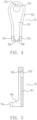
- the stop member 15 includes a board 151 and a flange 152 extending along a portion of the periphery of the board 151. In other words, the flange 152 does not close a lower end of the board 151.
- the board 151 has an aperture 153 defined therethrough, and the inner diameter of the aperture 153 is larger than the outer diameter of the end piece 23.
- the board 151 is mounted to the first extension 114, and the end piece 23 extends through the aperture 153 and contacts outside of the board 51.
- the flange 152 is mounted to the top and two sides of the first extension 114 and closes the first slot 118 at the top of the first extension 114.
- the cable 21 cannot disengaged from the first slot 118 by the stop member 15.
- the flange 152 has a tongue 155 extending therefrom which is engaged with the first slot 118 to prevent the cable 21 from disengaging from the first hole 116 via the first slot 118.
- the board 151 has two arms 154 extending therefrom which position the board 151 therebetween. Each arm 154 has a hooked end 156 which hooks the inside of the first extension 114 to secure the first extension 114 to the stop member 15.
- the stop member 15 When separating the cable unit 2 from the operation device 1, the stop member 15 is pulled away from the first extension 114 and the two arms 154 are expanded outward and the hooked ends 156 are disengaged from the first extension 114, so that the stop member 15 are separated from the first extension 114.
- the cable 21 is then pulled to pass through the first slot 118 and separated from the first extension 114.
- the positioning member 246 is separated from the second segment 244 so that the second segment 244 slides away from the second extension 124.
- the cable 21 then passes through the second slot 128 and is separated from the second extension 124.
- the cable unit 2 is successfully separated from the operation device 1.
- the sequence of steps for separating the cable unit 2 from the operation device 1 can be varied.
- the positioning member 246 can be first removed and then the stop member 15 is removed to separate the cable 21 from the first and second extensions 114, 124.
- the stop member 15 When connecting the cable unit 2 to the operation device 1, the stop member 15 is not yet connected to the first extension 114.
- the cable 21 passes through the first and second slots 118, 128 to enter into first and second holes 116, 126.
- the end piece 23 contacts the first extension 114.
- the second segment 244 enters into the second hole 126, and the positioning member 246 is mounted to the second segment 244 to position the insertion 24 to the second extension 124.
- the stop member 15 is then mounted to the first extension 114 to complete the connection between the cable unit 2 and the operation device 1.
- the cable unit 2 is easily separated from the operation device 1 without damaging the cable unit 2.
- the cable unit 2 and the working unit 3 can be replaced when the working unit 3 needs to be replaced.
- the different working units 3 are optionally replaced and chosen by separation/connection between the operation device 1 and the cable unit 2 so as to deal with different types of work.
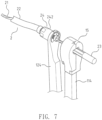
- Fig. 7 shows the second embodiment and comprises an operation device 1, a cable unit 3 and a working unit (not shown).
- the stop member 15 is mounted to the first extension 114 of the operation device 1.
- the stop member 15 includes a first side portion 162, a second side portion 163 and a first connection portion 164.
- a room 161 is defined in the stop member 15 and receives a portion of the first extension 114.
- the first side portion 162 faces the second side portion 163, and the first connection portion 164 is connected between the first and second side portions 162, 163.
- the first side portion 162 includes a first notch 1621 and a first recess 1622 defined in the inside thereof, and the second side portion 163 includes a second notch 1631 and a second recess 1632 defined in the inside thereof.
- the first notch 1621 is located corresponding to the second notch 1631, and the first recess 1622 is located corresponding to the second notch 1632.
- the first and second notches 1621, 1631 communicate with the front side of the room 161.
- the first and second recesses 1622, 1632 communicate with the rear side of the room 161.
- the cable 21 enters into the room 161 via the first and second notches 1621, 1631.
- the end piece 23 enters into the first and second recesses 1622, 1632 and contacts against the first extension 114.
- a first transverse portion 165 extends laterally from the first side portion 162 and includes a first engaging portion 166 on the distal end thereof which extends toward and contacts outside of the second side portion 163 so as to connect the first and second side portions 162, 163.
- the first engaging portion 166 When separating the cable unit 2 from the operation device 1, the first engaging portion 166 is disengaged from the second side portion 163.
- the first and second side portions 162, 163 are pivoted outward to move the stop member 15 upward so as to separate the stop member 15 from the first extension 114, and the cable 21 can be separated from the first extension 114.
- the positioning member 246 is then separated from the second segment 244, and the second segment 244 is slid to separate from the second extension 124.
- the cable 21 then passes through the second slot 128 and is separated from the second extension 124 to successfully separate the cable unit 2 from the operation device 1.
- the sequence of steps for separating the cable unit 2 from the operation device 1 can be varied.
- the positioning member 246 can be first removed and then the stop member 15 is removed to separate the cable 21 from the first and second extensions 114, 124.
- the stop member 15 When connecting the cable unit 2 to the operation device 1, the stop member 15 is not yet connected to the first extension 114.
- the cable 21 extends through the first and second extensions 114, 124.
- the end piece 23 contacts the first extension 114.
- the insertion 24 is positioned to the second extension 124.
- the stop member 15 is then mounted to the first extension 114 to complete the connection between the cable unit 2 and the operation device 1.
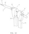
- Fig. 12 shows the third embodiment, and comprises an operation device 1, a cable unit 2 and a working unit (not shown), wherein the operation device 1 further includes a housing 17 mounted to the second extension 124 of the operation device 1.
- the housing 17 includes a space 171 in which a portion of the second extension 124 is accommodated.
- the housing 17 includes a first portion 172, a second portion 173 and a second connection portion 174.
- the first and second portions 172, 173 face each other, and the second connection portion 174 is connected between the first and second portions 172, 173.
- the first side portion 162 includes a third notch 1721 and a third recess 1722 defined in the inside thereof, and the second portion 173 includes a fourth notch 1731 and a fourth recess 1732 defined in the inside thereof.
- the third notch 1721 is located corresponding to the fourth notch 1731, and the third recess 1722 is located corresponding to the fourth recess 1732.
- the third and fourth notches 1721, 1731 communicate with the front side of the space 171.
- the third and fourth recesses 1722, 1732 communicate with the rear side of the space 171.
- the first segment 242 enters into the space 171 via the third and fourth recesses 1722, 1732, and contacts the second extension 124.
- the cable 21 extends through the third and fourth recesses 1722, 1732, and extends beyond the space 171.
- a second transverse portion 175 extends laterally from the second portion 173 and includes a second engaging portion 176 on the distal end thereof which extends toward and contacts outside of the first portion 172 so as to connect the first and second portions 172, 173.
- the second engaging portion 176 When separating the housing 17 from the first extension 114, the second engaging portion 176 is disengaged from the second portion 173.
- the first and second portions 172, 173 are pivoted outward to move the stop member 15 upward so as to separate the stop member 15 from the first extension 114.
- Fig. 17 which shows the fourth embodiment of the present invention, and comprises an operation device 1, a cable unit 2 and a working unit (not shown), wherein the sheath 22 is connected to the insertion 24 of the operation device 1.
- the insertion 24 includes a first segment 242 and a second segment 244.
- the first segment 242 extends through the second extension 124 of the operation device 1 and a positioning member 246 is mounted to the first segment 242.
- a housing 17 is mounted to the first segment 124.
- the positioning member 246 is formed by bending a metal wire.
- the top of the positioning member 246 extends through an outlet 177 defined through the top of the housing 17.
- the positioning member 246 includes a first section 2461, a second section 2462, a third section 2463, and a fourth section 2464.
- the first section 2461 is located to face the second section 2462, and the first section 2461 and the second section 2462 are integrally formed with each other at two respective top thereof. Two respective lower ends of the first section 2461 and the second section 2462 are located close to each other.
- the third section 2463 extends from the lower end of the first section 2461 at an angle
- the fourth section 2464 extends from the lower end of the second section 2462 at an angle.
- the distance between the third and fourth sections 2463, 2464 increases in a direction toward two respective distal ends of the third and fourth sections 2463, 2464.
- a clamp area 2465 is formed between the first and second sections 2461, 2462. When the second segment 244 enters into the clamp area 2465, the second segment 244 is clamped by the first and second sections 2461, 2462.
- the user holds the top of the positioning member 246 to move the lower end of the positioning member 246 close to the second segment 244, and to contact the third and fourth sections 2463, 2464 with the two sides of the second segment 244.
- the second segment 244 enters into the clamp area 244 and is clamped between the first and second sections 2461, 2462 so that the segment 24 is secured by the positioning member 246.
- the housing 17 is an optional part in the third and fourth embodiments.
- Figs. 19 , 20 and 21 respectively show the different working units 3 according to practical needs.
Landscapes
- Engineering & Computer Science (AREA)
- Mechanical Engineering (AREA)
- Electric Cable Arrangement Between Relatively Moving Parts (AREA)
- Electric Cable Installation (AREA)
- Flexible Shafts (AREA)
Claims (7)
- Dispositif de déverrouillage de fixations, comprenant :un dispositif opérationnel (1), une unité de câble (2) et une unité de travail (3), l'unité de câble (2) étant connectée entre le dispositif opérationnel (1) et l'unité de travail (3) ;le dispositif opérationnel (1) incluant une première partie (11),une seconde partie (12) et un pivot (13), les première et seconde parties (11, 12) étant connectées à pivotement ensemble au niveau de deux parties médianes respectives de celles-ci par le pivot (13), la première partie (11) incluant une première poignée (112) et une première extension (114) formées respectivement sur deux extrémités de celle-ci, la seconde partie (12) incluant une seconde poignée (122) et une seconde extension (124) formées respectivement sur deux extrémités de celle-ci, la première extension (114) comportant un premier trou (116), et la seconde extension (124) comportant un second trou (126) ;l'unité de câble (2) incluant un câble (21) et une gaine (22) le câble (21) s'étend, une première extrémité du câble (21) s'étendant au-delà d'une première extrémité de la gaine (22) et étant connectée au dispositif opérationnel (1), une seconde extrémité du câble (21) s'étendant au-delà d'une extrémité de la gaine (22) et étant connectée à l'unité de travail (3), la première extrémité du câble (21) s'étendant à travers le premier trou (116) et étant connectée à un embout (23) qui entre en contact avec la première extension (114), la gaine (22) ayant une première extrémité de celle-ci connectée à une insert (24) qui inclut un premier segment (242) et un second segment (244) qui est connecté axialement au premier segment (242), le premier segment (242) entrant en contact avec la seconde extension (124) et le second segment (244) s'étendant à travers le second trou (126) et étant fixé par un élément de positionnement (246) ; etcaractérisé en ce quela première extension (114) inclut une première fente (118) qui communique avec le premier trou (116), la seconde extension (124) inclut une seconde fente (128) qui communique avec le second trou (126), le câble (21) passe à travers le premier trou (116) via la première fente (118), le câble (21) passe à travers le second trou (126) via la seconde fente (128) ;la largeur de la seconde fente (128) étant inférieure au diamètre extérieur du second segment (244), et le dispositif opérationnel (1) incluant un élément d'arrêt (15) qui est monté sur la première extension (114) pour empêcher le câble (21) de se désengager du premier trou (116) via la première fente (118) ;et en ce que l'élément d'arrêt (15) inclut une première partie latérale (162), une seconde partie latérale (163) et une première partie de connexion (164), une chambre (161) est définie dans l'élément d'arrêt (15) et reçoit une partie de la première extension (114), la première partie latérale (162) fait face à la seconde partie latérale (163), la première partie de connexion (164) est connectée entre les première et seconde parties latérales (162, 163), la première partie latérale (162) inclut une première fente (1621) et un premier évidement (1622) définis dans un intérieur de celle-ci, la seconde partie latérale (163) inclut une seconde fente (1631) et un second évidement (1632) définis dans un intérieur de celle-ci, la première fente (1621) est située en correspondance de la seconde fente (1631), le premier évidement (1622) est situé en correspondance du second évidement (1632), les première et seconde fentes (1621, 1631) communiquent avec un côté avant de la chambre (161), les premier et second évidements (1622, 1632) communiquent avec un côté arrière de la chambre (161), le câble (21) entre dans la chambre (161) via les première et seconde fentes (1621, 1631), l'embout (23) entre dans les premier et second évidements (1622, 1632) et vient en contact contre la première extension (114), une première partie transversale (165) s'étend latéralement depuis la première partie latérale (162) et inclut une première partie de prise (166) sur une extrémité distale de celle-ci qui s'étend vers et entre en contact avec l'extérieur de la seconde partie latérale (163) de façon à connecter les première et seconde parties latérales (162, 163).
- Dispositif de déverrouillage de fixations selon la revendication 1, dans lequel l'élément d'arrêt (15) inclut une plaque (151) et un rebord (152) s'étendant le long d'une partie d'une périphérie de la plaque (151), la plaque (151) comporte une ouverture (153) définie à travers elle, la plaque (151) est montée sur la première extension (114), l'embout (23) s'étend à travers l'ouverture (153) et entre en contact avec l'extérieur de la plaque (151), le rebord (152) est monté sur un haut et deux côtés de la première extension (114) et ferme la première fente (118) au niveau du haut de la première extension (114), la plaque (151) comporte deux bras (154) s'étendant depuis celle-ci qui positionnent la plaque (151) entre eux, chaque bras (154) comporte une extrémité en crochet (156) qui accroche un intérieur de la première extension (114) pour fixer la première extension (114) sur l'élément d'arrêt (15).
- Dispositif de déverrouillage de fixations selon la revendication 1, dans lequel le rebord (152) comporte une languette (155) s'étendant depuis celui-ci qui est en prise avec la première fente (118) pour empêcher le câble (21) de se désengager du premier trou (116) via la première fente (118).
- Dispositif de déverrouillage de fixations selon la revendication 1, dans lequel la seconde extension (124) comporte un logement (17) monté sur elle, le logement (17) inclut un espace (171) dans lequel une partie de la seconde extension (124) est accueillie.
- Dispositif de déverrouillage de fixations selon la revendication 4, dans lequel le logement (17) inclut une première partie (172), une seconde partie (173) et une seconde partie de connexion (174), les première et seconde parties (172, 173) se font face, la seconde partie de connexion (174) est connectée entre les première et seconde parties (172, 173), la première partie latérale (162) inclut une troisième fente (1721) et un troisième évidement (1722) définis dans un intérieur de celle-ci, la seconde partie (173) inclut une quatrième fente (1731) et un quatrième évidement (1732) définis dans un intérieur de celle-ci, la troisième fente (1721) est située en correspondance de la quatrième fente (1731), le troisième évidement (1722) est situé en correspondance du quatrième évidement (1732), les troisième et quatrième fentes (1721, 1731) communiquent avec un côté avant de l'espace (171) les troisième et quatrième évidements (1722, 1732) communiquent avec un côté arrière de l'espace (171), le premier segment (242) entre dans l'espace (171) via les troisième et quatrième évidements (1722, 1732), et entre en contact avec la seconde extension (124), le câble (21) s'étend à travers les troisième et quatrième évidements (1722, 1732), et s'étend au-delà de l'espace (171), une seconde partie transversale (175) s'étend latéralement depuis la seconde partie (173) et inclut une seconde partie de prise (176) sur une extrémité distale de celle-ci qui s'étend vers et entre en contact avec l'extérieur de la première partie (172) de façon à connecter les première et seconde parties (172, 173).
- Dispositif de déverrouillage de fixations selon la revendication 5, dans lequel le logement (17) inclut un orifice de sortie (177), l'élément de positionnement (246) formé en courbant un fil métallique, un haut de l'élément de positionnement (246) s'étend à travers l'orifice de sortie (177), l'élément de positionnement (246) inclut une première section (2461), une seconde section (2462), une troisième section (2463), et une quatrième section (2464), la première section (2461) est située face à la seconde section (2462), la première section (2461) et la seconde section (2462) sont reliées ensemble par leurs hauts respectifs, deux extrémités inférieures respectives de la première section (2461) et la seconde section (2462) sont situées proches l'une de l'autre, la troisième section (2463) s'étend depuis l'extrémité inférieure de la seconde section (2462) en formant un angle, une distance entre les troisième et quatrième sections (2463, 2464) augmente dans une direction vers deux extrémités distales respectives des troisième et quatrième sections (2463, 2464), une zone de pincement (2465) est formée entre les première et seconde sections (2461, 2462), quand le second segment (244) entre dans la zone de pincement (2465), le second segment (244) est pincé par les première et seconde sections (2461, 2462).
- Dispositif de déverrouillage de fixations selon la revendication 1, dans lequel l'élément de positionnement (246) est un circlip.
Applications Claiming Priority (1)
| Application Number | Priority Date | Filing Date | Title |
|---|---|---|---|
| TW106111824A TWI633981B (zh) | 2017-04-07 | 2017-04-07 | 可更換工作單元的遠端操作工具 |
Publications (2)
| Publication Number | Publication Date |
|---|---|
| EP3385033A1 EP3385033A1 (fr) | 2018-10-10 |
| EP3385033B1 true EP3385033B1 (fr) | 2024-06-12 |
Family
ID=61024676
Family Applications (1)
| Application Number | Title | Priority Date | Filing Date |
|---|---|---|---|
| EP18153251.6A Active EP3385033B1 (fr) | 2017-04-07 | 2018-01-24 | Dispositif de déverrouillage de fixations de tuyau |
Country Status (3)
| Country | Link |
|---|---|
| US (1) | US10688636B2 (fr) |
| EP (1) | EP3385033B1 (fr) |
| TW (1) | TWI633981B (fr) |
Families Citing this family (5)
| Publication number | Priority date | Publication date | Assignee | Title |
|---|---|---|---|---|
| US11661752B2 (en) * | 2016-12-18 | 2023-05-30 | Hangzhou United Tools Co., Ltd | Ceramic tile leveling bracket, pushing and clamping pliers, and ceramic tile leveling and laying system |
| TWI611877B (zh) * | 2017-02-23 | 2018-01-21 | 昱鋒實業有限公司 | 拆解管接頭的工具 |
| TWI665060B (zh) * | 2018-07-24 | 2019-07-11 | 昱鋒實業股份有限公司 | 可更換工作單元的遠端操作工具 |
| US11247260B1 (en) * | 2019-09-10 | 2022-02-15 | Emad Othman | Tube connector crimping tool |
| TWD214854S (zh) * | 2021-01-06 | 2021-10-21 | 昱鋒實業股份有限公司 | 油管接頭拆卸工具 |
Family Cites Families (29)
| Publication number | Priority date | Publication date | Assignee | Title |
|---|---|---|---|---|
| US2842991A (en) * | 1955-09-26 | 1958-07-15 | Lasher Walter Ray | Clamp installation tool |
| US3596686A (en) * | 1969-11-03 | 1971-08-03 | Cast Iron Soil Pipe Inst | Applying tool for wire-type clamp |
| US4141262A (en) * | 1977-05-06 | 1979-02-27 | Smith Clyde D | Remote operated wrench |
| US4423860A (en) * | 1982-05-10 | 1984-01-03 | Windstrup Robert F | Vise clamp |
| US4619446A (en) * | 1985-01-03 | 1986-10-28 | Yang Tai Her | Adjustable support arm-type three-dimensional work bench |
| US4823486A (en) * | 1987-01-20 | 1989-04-25 | Caterpillar Inc. | Positive keeper means for pins of earthworking tips |
| FR2757439B1 (fr) * | 1996-12-19 | 1999-01-15 | Gillet Outillage | Systeme de telemanipulation d'un outillage particulierement adapte aux colliers elastiques |
| US6276236B1 (en) * | 1999-12-06 | 2001-08-21 | Pi-Liang Wu | Clamp apparatus |
| DE10026847A1 (de) * | 2000-05-31 | 2002-01-10 | Engelbert Gmeilbauer | Werkzeug zum Spannen bzw. Lösen/Öffnen von Feder-Klemmelementen |
| US6370985B1 (en) * | 2000-09-18 | 2002-04-16 | Pi-Liang Wu | Extractor tool for pipe coupling |
| US6634258B2 (en) * | 2001-05-31 | 2003-10-21 | Lisle Corporation | Automotive hose clamp removal tool |
| TW517625U (en) * | 2002-04-29 | 2003-01-11 | Jia-Shiung Huang | Improvement for replaceable pipe pincer |
| US6736031B1 (en) * | 2003-01-03 | 2004-05-18 | Hsin Fa Kang | Pliers for disassembling a pipe fastening clamp |
| US6775891B1 (en) * | 2003-01-24 | 2004-08-17 | Todd Tsiguloff | Table top apparatus for fitting grips to shafts |
| TWM253450U (en) * | 2003-11-19 | 2004-12-21 | Jeng-Shiung Liou | Improved structure for bendable throat type tube binding pincer |
| US7313984B1 (en) * | 2005-07-27 | 2008-01-01 | Snap-On Incorporated | Universal retention cavities for cable-mounted remote hose clamp pliers heads |
| TWM287208U (en) * | 2005-08-17 | 2006-02-11 | Auto Skill Ind Co Ltd | Improved clinching structure of tube pliers |
| DE202007015465U1 (de) * | 2007-11-07 | 2008-01-10 | Huang, Chuan Mao, Beitun | Zange |
| US8733805B2 (en) * | 2011-07-27 | 2014-05-27 | Nic Products Inc. | Security seal assembly |
| TW201309932A (zh) * | 2011-08-30 | 2013-03-01 | Auto Skill Ind Co Ltd | 管件束環的拆裝工具 |
| TWM435346U (en) * | 2012-03-01 | 2012-08-11 | Fan Xiu Lan | Easy-clamp-replacement hose clamp pliers |
| TWM436346U (en) | 2012-04-20 | 2012-09-01 | On Time Medical Co Ltd | Improved multifunctional rehabilitation strap structure |
| FR2991223B1 (fr) * | 2012-06-01 | 2014-06-13 | Gillet Group | Telemanipulateur a cable universel |
| TWM484495U (zh) * | 2014-03-21 | 2014-08-21 | Ruan Xue Rong | 可固定工作角度之管束鉗 |
| TWM517625U (zh) | 2015-11-10 | 2016-02-21 | Yun-Wan Lu | 健身器材 |
| US9939008B2 (en) * | 2016-01-15 | 2018-04-10 | Matteo Enterprises Ltd. | Remote throttle control for a throttle trigger of a vehicle |
| GB201603926D0 (en) * | 2016-03-07 | 2016-04-20 | Buchanan Nigel | Portable vice pliers |
| TWI611877B (zh) * | 2017-02-23 | 2018-01-21 | 昱鋒實業有限公司 | 拆解管接頭的工具 |
| US20190184531A1 (en) * | 2017-12-15 | 2019-06-20 | Ching-Shu Wang | Hose clamp pliers |
-
2017
- 2017-04-07 TW TW106111824A patent/TWI633981B/zh active
- 2017-07-10 US US15/644,838 patent/US10688636B2/en active Active
-
2018
- 2018-01-24 EP EP18153251.6A patent/EP3385033B1/fr active Active
Also Published As
| Publication number | Publication date |
|---|---|
| US20180290276A1 (en) | 2018-10-11 |
| US10688636B2 (en) | 2020-06-23 |
| TWI633981B (zh) | 2018-09-01 |
| TW201836783A (zh) | 2018-10-16 |
| EP3385033A1 (fr) | 2018-10-10 |
Similar Documents
| Publication | Publication Date | Title |
|---|---|---|
| US10688636B2 (en) | Device for unfastening pipe fasteners | |
| CN107076340B (zh) | 具有固位夹子构件的联接组件 | |
| US6370985B1 (en) | Extractor tool for pipe coupling | |
| US6644884B2 (en) | Rotational spring clip for connecting a male component to a female component | |
| EP0650003A1 (fr) | Collier de serrage universel pour systèmes externes de câbles électriques, téléphoniques, ou tuyaux fixés sur une paroi | |
| EP3338952B1 (fr) | Outil d'atteinte et de préhension avec têtes de préhension améliorées | |
| US6480384B2 (en) | Clip for heat sink | |
| US8458877B1 (en) | Air hose removal tool | |
| US5590573A (en) | Pair of jaw fittings for mounting on pliers for clamping a collar | |
| US6456493B1 (en) | Heat sink clip | |
| CN101400936B (zh) | 软管夹 | |
| EP3366422B1 (fr) | Outil de retrait d'articulation | |
| EP0950472A1 (fr) | Pince | |
| US6192555B1 (en) | Hose clip of the self-holding type | |
| US20020073557A1 (en) | Expandable tubular body | |
| US11999033B2 (en) | Drain cleaner cable decoupler tool | |
| SE524776C2 (sv) | Koppling för städredskap med fjäderbelastad manöverknapp och låstapp | |
| WO2014052008A1 (fr) | Éléments de mâchoire remplaçables pour pinces | |
| US7104162B1 (en) | Device for unfastening pipe fasteners | |
| US20060053608A1 (en) | Pipe disassembling tool | |
| US20060103097A1 (en) | Folding structure for a scooter | |
| CN212653375U (zh) | 车用导线的尾套钳具 | |
| US6276236B1 (en) | Clamp apparatus | |
| US7272994B1 (en) | Bolt grasping device | |
| TWM435346U (en) | Easy-clamp-replacement hose clamp pliers |
Legal Events
| Date | Code | Title | Description |
|---|---|---|---|
| PUAI | Public reference made under article 153(3) epc to a published international application that has entered the european phase |
Free format text: ORIGINAL CODE: 0009012 |
|
| STAA | Information on the status of an ep patent application or granted ep patent |
Free format text: STATUS: THE APPLICATION HAS BEEN PUBLISHED |
|
| AK | Designated contracting states |
Kind code of ref document: A1 Designated state(s): AL AT BE BG CH CY CZ DE DK EE ES FI FR GB GR HR HU IE IS IT LI LT LU LV MC MK MT NL NO PL PT RO RS SE SI SK SM TR |
|
| AX | Request for extension of the european patent |
Extension state: BA ME |
|
| RBV | Designated contracting states (corrected) |
Designated state(s): AL AT BE BG CH CY CZ DE DK EE ES FI FR GB GR HR HU IE IS IT LI LT LU LV MC MK MT NL NO PL PT RO RS SE SI SK SM TR |
|
| STAA | Information on the status of an ep patent application or granted ep patent |
Free format text: STATUS: REQUEST FOR EXAMINATION WAS MADE |
|
| 17P | Request for examination filed |
Effective date: 20190429 |
|
| RIC1 | Information provided on ipc code assigned before grant |
Ipc: B25B 25/00 20060101ALI20231121BHEP Ipc: B25B 7/02 20060101AFI20231121BHEP |
|
| GRAP | Despatch of communication of intention to grant a patent |
Free format text: ORIGINAL CODE: EPIDOSNIGR1 |
|
| STAA | Information on the status of an ep patent application or granted ep patent |
Free format text: STATUS: GRANT OF PATENT IS INTENDED |
|
| INTG | Intention to grant announced |
Effective date: 20240117 |
|
| GRAS | Grant fee paid |
Free format text: ORIGINAL CODE: EPIDOSNIGR3 |
|
| GRAA | (expected) grant |
Free format text: ORIGINAL CODE: 0009210 |
|
| STAA | Information on the status of an ep patent application or granted ep patent |
Free format text: STATUS: THE PATENT HAS BEEN GRANTED |
|
| AK | Designated contracting states |
Kind code of ref document: B1 Designated state(s): AL AT BE BG CH CY CZ DE DK EE ES FI FR GB GR HR HU IE IS IT LI LT LU LV MC MK MT NL NO PL PT RO RS SE SI SK SM TR |
|
| REG | Reference to a national code |
Ref country code: GB Ref legal event code: FG4D |
|
| REG | Reference to a national code |
Ref country code: CH Ref legal event code: EP |
|
| REG | Reference to a national code |
Ref country code: DE Ref legal event code: R096 Ref document number: 602018070453 Country of ref document: DE |
|
| REG | Reference to a national code |
Ref country code: IE Ref legal event code: FG4D |
|
| PG25 | Lapsed in a contracting state [announced via postgrant information from national office to epo] |
Ref country code: BG Free format text: LAPSE BECAUSE OF FAILURE TO SUBMIT A TRANSLATION OF THE DESCRIPTION OR TO PAY THE FEE WITHIN THE PRESCRIBED TIME-LIMIT Effective date: 20240612 |
|
| PG25 | Lapsed in a contracting state [announced via postgrant information from national office to epo] |
Ref country code: HR Free format text: LAPSE BECAUSE OF FAILURE TO SUBMIT A TRANSLATION OF THE DESCRIPTION OR TO PAY THE FEE WITHIN THE PRESCRIBED TIME-LIMIT Effective date: 20240612 Ref country code: FI Free format text: LAPSE BECAUSE OF FAILURE TO SUBMIT A TRANSLATION OF THE DESCRIPTION OR TO PAY THE FEE WITHIN THE PRESCRIBED TIME-LIMIT Effective date: 20240612 |
|
| REG | Reference to a national code |
Ref country code: LT Ref legal event code: MG9D |
|
| PG25 | Lapsed in a contracting state [announced via postgrant information from national office to epo] |
Ref country code: GR Free format text: LAPSE BECAUSE OF FAILURE TO SUBMIT A TRANSLATION OF THE DESCRIPTION OR TO PAY THE FEE WITHIN THE PRESCRIBED TIME-LIMIT Effective date: 20240913 |
|
| REG | Reference to a national code |
Ref country code: NL Ref legal event code: MP Effective date: 20240612 |
|
| PG25 | Lapsed in a contracting state [announced via postgrant information from national office to epo] |
Ref country code: ES Free format text: LAPSE BECAUSE OF FAILURE TO SUBMIT A TRANSLATION OF THE DESCRIPTION OR TO PAY THE FEE WITHIN THE PRESCRIBED TIME-LIMIT Effective date: 20240612 |
|
| PG25 | Lapsed in a contracting state [announced via postgrant information from national office to epo] |
Ref country code: LV Free format text: LAPSE BECAUSE OF FAILURE TO SUBMIT A TRANSLATION OF THE DESCRIPTION OR TO PAY THE FEE WITHIN THE PRESCRIBED TIME-LIMIT Effective date: 20240612 |
|
| PG25 | Lapsed in a contracting state [announced via postgrant information from national office to epo] |
Ref country code: NO Free format text: LAPSE BECAUSE OF FAILURE TO SUBMIT A TRANSLATION OF THE DESCRIPTION OR TO PAY THE FEE WITHIN THE PRESCRIBED TIME-LIMIT Effective date: 20240912 Ref country code: LV Free format text: LAPSE BECAUSE OF FAILURE TO SUBMIT A TRANSLATION OF THE DESCRIPTION OR TO PAY THE FEE WITHIN THE PRESCRIBED TIME-LIMIT Effective date: 20240612 Ref country code: HR Free format text: LAPSE BECAUSE OF FAILURE TO SUBMIT A TRANSLATION OF THE DESCRIPTION OR TO PAY THE FEE WITHIN THE PRESCRIBED TIME-LIMIT Effective date: 20240612 Ref country code: GR Free format text: LAPSE BECAUSE OF FAILURE TO SUBMIT A TRANSLATION OF THE DESCRIPTION OR TO PAY THE FEE WITHIN THE PRESCRIBED TIME-LIMIT Effective date: 20240913 Ref country code: FI Free format text: LAPSE BECAUSE OF FAILURE TO SUBMIT A TRANSLATION OF THE DESCRIPTION OR TO PAY THE FEE WITHIN THE PRESCRIBED TIME-LIMIT Effective date: 20240612 Ref country code: ES Free format text: LAPSE BECAUSE OF FAILURE TO SUBMIT A TRANSLATION OF THE DESCRIPTION OR TO PAY THE FEE WITHIN THE PRESCRIBED TIME-LIMIT Effective date: 20240612 Ref country code: BG Free format text: LAPSE BECAUSE OF FAILURE TO SUBMIT A TRANSLATION OF THE DESCRIPTION OR TO PAY THE FEE WITHIN THE PRESCRIBED TIME-LIMIT Effective date: 20240612 Ref country code: RS Free format text: LAPSE BECAUSE OF FAILURE TO SUBMIT A TRANSLATION OF THE DESCRIPTION OR TO PAY THE FEE WITHIN THE PRESCRIBED TIME-LIMIT Effective date: 20240912 |
|
| PG25 | Lapsed in a contracting state [announced via postgrant information from national office to epo] |
Ref country code: NL Free format text: LAPSE BECAUSE OF FAILURE TO SUBMIT A TRANSLATION OF THE DESCRIPTION OR TO PAY THE FEE WITHIN THE PRESCRIBED TIME-LIMIT Effective date: 20240612 |
|
| REG | Reference to a national code |
Ref country code: AT Ref legal event code: MK05 Ref document number: 1693830 Country of ref document: AT Kind code of ref document: T Effective date: 20240612 |
|
| PG25 | Lapsed in a contracting state [announced via postgrant information from national office to epo] |
Ref country code: NL Free format text: LAPSE BECAUSE OF FAILURE TO SUBMIT A TRANSLATION OF THE DESCRIPTION OR TO PAY THE FEE WITHIN THE PRESCRIBED TIME-LIMIT Effective date: 20240612 |
|
| PG25 | Lapsed in a contracting state [announced via postgrant information from national office to epo] |
Ref country code: PT Free format text: LAPSE BECAUSE OF FAILURE TO SUBMIT A TRANSLATION OF THE DESCRIPTION OR TO PAY THE FEE WITHIN THE PRESCRIBED TIME-LIMIT Effective date: 20241014 |
|
| PG25 | Lapsed in a contracting state [announced via postgrant information from national office to epo] |
Ref country code: PT Free format text: LAPSE BECAUSE OF FAILURE TO SUBMIT A TRANSLATION OF THE DESCRIPTION OR TO PAY THE FEE WITHIN THE PRESCRIBED TIME-LIMIT Effective date: 20241014 |
|
| PG25 | Lapsed in a contracting state [announced via postgrant information from national office to epo] |
Ref country code: PL Free format text: LAPSE BECAUSE OF FAILURE TO SUBMIT A TRANSLATION OF THE DESCRIPTION OR TO PAY THE FEE WITHIN THE PRESCRIBED TIME-LIMIT Effective date: 20240612 |
|
| PG25 | Lapsed in a contracting state [announced via postgrant information from national office to epo] |
Ref country code: EE Free format text: LAPSE BECAUSE OF FAILURE TO SUBMIT A TRANSLATION OF THE DESCRIPTION OR TO PAY THE FEE WITHIN THE PRESCRIBED TIME-LIMIT Effective date: 20240612 |
|
| PG25 | Lapsed in a contracting state [announced via postgrant information from national office to epo] |
Ref country code: AT Free format text: LAPSE BECAUSE OF FAILURE TO SUBMIT A TRANSLATION OF THE DESCRIPTION OR TO PAY THE FEE WITHIN THE PRESCRIBED TIME-LIMIT Effective date: 20240612 Ref country code: IS Free format text: LAPSE BECAUSE OF FAILURE TO SUBMIT A TRANSLATION OF THE DESCRIPTION OR TO PAY THE FEE WITHIN THE PRESCRIBED TIME-LIMIT Effective date: 20241012 |
|
| PG25 | Lapsed in a contracting state [announced via postgrant information from national office to epo] |
Ref country code: CZ Free format text: LAPSE BECAUSE OF FAILURE TO SUBMIT A TRANSLATION OF THE DESCRIPTION OR TO PAY THE FEE WITHIN THE PRESCRIBED TIME-LIMIT Effective date: 20240612 |
|
| PG25 | Lapsed in a contracting state [announced via postgrant information from national office to epo] |
Ref country code: RO Free format text: LAPSE BECAUSE OF FAILURE TO SUBMIT A TRANSLATION OF THE DESCRIPTION OR TO PAY THE FEE WITHIN THE PRESCRIBED TIME-LIMIT Effective date: 20240612 Ref country code: SK Free format text: LAPSE BECAUSE OF FAILURE TO SUBMIT A TRANSLATION OF THE DESCRIPTION OR TO PAY THE FEE WITHIN THE PRESCRIBED TIME-LIMIT Effective date: 20240612 |
|
| PG25 | Lapsed in a contracting state [announced via postgrant information from national office to epo] |
Ref country code: SM Free format text: LAPSE BECAUSE OF FAILURE TO SUBMIT A TRANSLATION OF THE DESCRIPTION OR TO PAY THE FEE WITHIN THE PRESCRIBED TIME-LIMIT Effective date: 20240612 |
|
| PG25 | Lapsed in a contracting state [announced via postgrant information from national office to epo] |
Ref country code: SM Free format text: LAPSE BECAUSE OF FAILURE TO SUBMIT A TRANSLATION OF THE DESCRIPTION OR TO PAY THE FEE WITHIN THE PRESCRIBED TIME-LIMIT Effective date: 20240612 Ref country code: SK Free format text: LAPSE BECAUSE OF FAILURE TO SUBMIT A TRANSLATION OF THE DESCRIPTION OR TO PAY THE FEE WITHIN THE PRESCRIBED TIME-LIMIT Effective date: 20240612 Ref country code: RO Free format text: LAPSE BECAUSE OF FAILURE TO SUBMIT A TRANSLATION OF THE DESCRIPTION OR TO PAY THE FEE WITHIN THE PRESCRIBED TIME-LIMIT Effective date: 20240612 Ref country code: PL Free format text: LAPSE BECAUSE OF FAILURE TO SUBMIT A TRANSLATION OF THE DESCRIPTION OR TO PAY THE FEE WITHIN THE PRESCRIBED TIME-LIMIT Effective date: 20240612 Ref country code: IS Free format text: LAPSE BECAUSE OF FAILURE TO SUBMIT A TRANSLATION OF THE DESCRIPTION OR TO PAY THE FEE WITHIN THE PRESCRIBED TIME-LIMIT Effective date: 20241012 Ref country code: EE Free format text: LAPSE BECAUSE OF FAILURE TO SUBMIT A TRANSLATION OF THE DESCRIPTION OR TO PAY THE FEE WITHIN THE PRESCRIBED TIME-LIMIT Effective date: 20240612 Ref country code: CZ Free format text: LAPSE BECAUSE OF FAILURE TO SUBMIT A TRANSLATION OF THE DESCRIPTION OR TO PAY THE FEE WITHIN THE PRESCRIBED TIME-LIMIT Effective date: 20240612 Ref country code: AT Free format text: LAPSE BECAUSE OF FAILURE TO SUBMIT A TRANSLATION OF THE DESCRIPTION OR TO PAY THE FEE WITHIN THE PRESCRIBED TIME-LIMIT Effective date: 20240612 |
|
| PG25 | Lapsed in a contracting state [announced via postgrant information from national office to epo] |
Ref country code: IT Free format text: LAPSE BECAUSE OF FAILURE TO SUBMIT A TRANSLATION OF THE DESCRIPTION OR TO PAY THE FEE WITHIN THE PRESCRIBED TIME-LIMIT Effective date: 20240612 |
|
| REG | Reference to a national code |
Ref country code: DE Ref legal event code: R097 Ref document number: 602018070453 Country of ref document: DE |
|
| PG25 | Lapsed in a contracting state [announced via postgrant information from national office to epo] |
Ref country code: DK Free format text: LAPSE BECAUSE OF FAILURE TO SUBMIT A TRANSLATION OF THE DESCRIPTION OR TO PAY THE FEE WITHIN THE PRESCRIBED TIME-LIMIT Effective date: 20240612 |
|
| PLBE | No opposition filed within time limit |
Free format text: ORIGINAL CODE: 0009261 |
|
| STAA | Information on the status of an ep patent application or granted ep patent |
Free format text: STATUS: NO OPPOSITION FILED WITHIN TIME LIMIT |
|
| 26N | No opposition filed |
Effective date: 20250313 |
|
| REG | Reference to a national code |
Ref country code: CH Ref legal event code: PL |
|
| PG25 | Lapsed in a contracting state [announced via postgrant information from national office to epo] |
Ref country code: SE Free format text: LAPSE BECAUSE OF FAILURE TO SUBMIT A TRANSLATION OF THE DESCRIPTION OR TO PAY THE FEE WITHIN THE PRESCRIBED TIME-LIMIT Effective date: 20240612 |
|
| PG25 | Lapsed in a contracting state [announced via postgrant information from national office to epo] |
Ref country code: MC Free format text: LAPSE BECAUSE OF FAILURE TO SUBMIT A TRANSLATION OF THE DESCRIPTION OR TO PAY THE FEE WITHIN THE PRESCRIBED TIME-LIMIT Effective date: 20240612 Ref country code: LU Free format text: LAPSE BECAUSE OF NON-PAYMENT OF DUE FEES Effective date: 20250124 |
|
| PG25 | Lapsed in a contracting state [announced via postgrant information from national office to epo] |
Ref country code: BE Free format text: LAPSE BECAUSE OF NON-PAYMENT OF DUE FEES Effective date: 20250131 |
|
| PG25 | Lapsed in a contracting state [announced via postgrant information from national office to epo] |
Ref country code: CH Free format text: LAPSE BECAUSE OF NON-PAYMENT OF DUE FEES Effective date: 20250131 |
|
| REG | Reference to a national code |
Ref country code: BE Ref legal event code: MM Effective date: 20250131 |
|
| PG25 | Lapsed in a contracting state [announced via postgrant information from national office to epo] |
Ref country code: IE Free format text: LAPSE BECAUSE OF NON-PAYMENT OF DUE FEES Effective date: 20250124 |
|
| PGFP | Annual fee paid to national office [announced via postgrant information from national office to epo] |
Ref country code: GB Payment date: 20260127 Year of fee payment: 9 |
|
| PGFP | Annual fee paid to national office [announced via postgrant information from national office to epo] |
Ref country code: DE Payment date: 20260114 Year of fee payment: 9 |
|
| PGFP | Annual fee paid to national office [announced via postgrant information from national office to epo] |
Ref country code: FR Payment date: 20260128 Year of fee payment: 9 |