EP3385036A1 - Griffstruktur für links- und rechtshänder - Google Patents
Griffstruktur für links- und rechtshänder Download PDFInfo
- Publication number
- EP3385036A1 EP3385036A1 EP17165147.4A EP17165147A EP3385036A1 EP 3385036 A1 EP3385036 A1 EP 3385036A1 EP 17165147 A EP17165147 A EP 17165147A EP 3385036 A1 EP3385036 A1 EP 3385036A1
- Authority
- EP
- European Patent Office
- Prior art keywords
- grip
- base
- hole
- cantilever
- embedding
- Prior art date
- Legal status (The legal status is an assumption and is not a legal conclusion. Google has not performed a legal analysis and makes no representation as to the accuracy of the status listed.)
- Withdrawn
Links
Images




Classifications
-
- B—PERFORMING OPERATIONS; TRANSPORTING
- B25—HAND TOOLS; PORTABLE POWER-DRIVEN TOOLS; MANIPULATORS
- B25G—HANDLES FOR HAND IMPLEMENTS
- B25G1/00—Handle constructions
- B25G1/10—Handle constructions characterised by material or shape
- B25G1/102—Handle constructions characterised by material or shape the shape being specially adapted to facilitate handling or improve grip
-
- B—PERFORMING OPERATIONS; TRANSPORTING
- B25—HAND TOOLS; PORTABLE POWER-DRIVEN TOOLS; MANIPULATORS
- B25G—HANDLES FOR HAND IMPLEMENTS
- B25G1/00—Handle constructions
- B25G1/06—Handle constructions reversible or adjustable for position
Definitions
- the present invention relates to grip structures and more particularly, to a grip structure for left-handed and right-handed users.
- the conventional hand tool such as the saw, is primarily handled by the hand of the user holding the hand tool.
- the hand tool is usually provided at a terminal end thereof with a grip structure conforming to ergonomics, allowing the user to hold the grip structure perfectly and apply force conveniently.
- the related dealers should manufacture two kinds of grip structures adapted for the left hand and the right hand respectively for matching the dominant hands of different users, that can satisfy the usage requirements of the users but certainly increases the manufacturing cost. Therefore, in consideration of the manufacturing cost, a part of the dealers manufacture the grip structure adapted for both the left hand and the right hand. But such grip structure for both the left and right hands is not good in hand feel, thereby more difficultly applied with force when being handled.
- the grip structure of the present invention includes a grip base and a grip.
- the grip base has a first lateral surface and a second lateral surface opposite to the first lateral surface.
- the grip is detachably disposed on the grip base and changeable between a right-hand usage mode and a left-hand usage mode by being mounted with or dismounted from the grip base along a first direction, so that the grip is able to be applied with an external force to move together with the grip base along a second direction non-parallel to the first direction.
- the grip has a finger abutting portion formed on a circumferential surface of the grip along the first direction for the fingers of the user to be abutted on the finger abutting portion to apply force conveniently.
- the grip structure of the present invention allows the user to change the usage mode of the grip according to the dominant hand of the user, thereby increased in the convenience of usage, lowered in manufacturing cost, and good in hand feel of usage.
- the finger abutting portion is protruded out of the circumferential surface of the grip along the first direction.
- a pass-through space is formed between the grip and the grip base.
- the finger abutting portion of the grip is arc-shaped and provided with an opening toward the pass-through space. In this way, when the hand of the user holds the grip, the thumb is abutted on the circumferential surface of the grip, and the other four fingers are inserted in the pass-through space and placed on the finger abutting portion at the opening thereof, so that the user can apply force to the grip conveniently.
- the grip base has a base body provided at an end thereof with a saw blade fastening groove; a cantilever portion is extended away from the saw blade fastening groove from another end of the base body along the second direction; an end of the grip is detachably mounted to a terminal end of the cantilever portion.
- the pass-through space is formed between the base body of the grip base, the cantilever portion of the grip base and the grip.
- the cantilever portion of the grip base has a through hole; the grip has a threaded hole; the grip is fastened to the cantilever portion of the grip base by a fastener inserted through the through hole of the cantilever portion of the grip base and screwed into the threaded hole of the grip.
- the cantilever portion of the grip base has an embedding groove communicating with the through hole and extended along a direction parallel to the first direction; the grip is provided at each of two ends thereof with an embedding portion and embedded in the embedding groove by one of the embedding portions.
- the grip can be positioned on the grip base quickly for the convenience of the follow-up being fastened.
- the grip in use can be prevented from being rotated and affecting the user handling the grip structure.
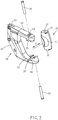
- the grip structure 10 of the present invention includes a grip base 20 and a grip 30.
- the grip base 20 has a first lateral surface 26 and a second lateral surface 27 opposite to the first lateral surface 26.
- the first lateral surface 26 corresponds to the left side of the user
- the second lateral surface 27 corresponds to the right side of the user.
- the grip base 20 has a base body 21 provided at a front end thereof with a saw blade fastening groove 22 for a saw blade 12 to be fixedly inserted therein.
- Two cantilever portions 23 facing each other are extended away from the saw blade fastening groove 22 from a rear end of the base body 21 along a second direction D2.
- Each of the two cantilever portions 23 is provided at a terminal end thereof with a through hole 24 and an embedding groove 25 communicating with the through hole 24, and the embedding grooves 25 are located on the sides of the cantilever portions 23 facing each other.
- the embedding groove 25 is extended along a direction parallel to a first direction D1 non-parallel to the second direction D2. In this embodiment, the first direction D1 is perpendicular to the second direction D2.
- the grip 30 is provided at each of top and bottom ends thereof with an embedding portion 31 and a threaded hole 32 located on the embedding portion 31.
- the grip 30 When being mounted with the grip base 20, the grip 30 is firstly positioned in a way that the embedding portions 31 are embedded in the embedding grooves 25 of the cantilever portions 23 of the grip base 20 along the first direction D1, and then fastened in a way that two bolts 33 are respectively inserted through the through holes 24 of the cantilever portions 23 of the grip base 20 and screwed into the threaded holes 32 of the grip 30.
- a pass-through space 34 is formed between the base body 21 of the grip base 20, the two cantilever portions 23 of the grip base 20 and the grip 30.
- the grip 30 is dismounted from the grip base 20 along the first direction D1 after the two bolts 33 are removed.
- the grip 30 has a finger abutting portion 35 protruded out of the circumferential surface of the grip 30 along the first direction D1.
- the finger abutting portion 35 is arc-shaped and provided with an opening 36 toward the pass-through space 34.
- the grip 30 after being mounted with the grip base 20 should be in a right-hand usage mode P1 wherein the finger abutting portion 35 and the first lateral surface 26 of the grip base 20 (i.e. the left side of the user) are located on the same side, as shown in FIGS. 1 and 3 .
- the grip 30 should be firstly dismounted from the grip base 20 and then remounted with the grip base 20 after being turned vertically and horizontally, thereby changed to a left-hand usage mode P2 wherein the finger abutting portion 35 of the grip 30 and the second lateral surface 27 of the grip base 20 (i.e. the right side of the user) are located on the same side, as shown in FIGS. 4 and 5 .
- the hand of the user holds the grip 30 in a way that the thumb is abutted on the circumferential surface of the grip 30 and the other four fingers are inserted in the pass-through space 34 and placed on the finger abutting portion 35 at the opening 36 thereof.
- the user can start to apply force to the grip 30 along the second direction D2.
- the grip 30 and the grip base 20 are moved together forwards and backwards along the second direction D2, allowing the saw blade 12 fixed to the grip base 20 to do the cutting.
- the embedding between the embedding portions 31 and the embedding grooves 25 can prevent the grip 30 from being rotated and affecting the user handling the grip structure.
- the grip base is unlimited to be used with the saw blade 12 and variable in structure.
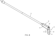
- the grip base 40 is provided at an end thereof with a fastening hole 42 for an end of a pipe 14 to be fixedly inserted in the fastening hole 42.
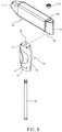
- the grip base 40 is provided at another end thereof with a cantilever portion 44 which has a countersunk hole 46 and an embedding groove 48 communicating with the countersunk hole 46.
- the grip 50 has a bolt hole 54.
- the grip 50 is fastened to the cantilever portion 44 of the grip base 40 by a bolt 60 which is inserted through the bolt hole 54 and screwed with a nut 62 disposed in the countersunk hole 46.
- the grip 50 is provided at an end thereof with a first embedding portion 51, and provided at another end thereof with a second embedding portion 52.
- the grip 50 is positioned in a way that the first embedding portion 51 is embedded in the embedding groove 48 of the cantilever portion 44 of the grip base 40 and the second embedding portion 52 of the grip 50 is embedded in a terminal cap 53, so that the grip 50 is disposed in a way that the finger abutting portion 55 and the first lateral surface 41 of the grip base 40 (i.e. the left side of the user) are located on the same side.
- the grip 50 is firstly dismounted from the grip base 40, then the terminal cap 53 is dismounted from the second embedding portion 52 of the grip 50 and embedded with the first embedding portion 51 of the grip 50, and at last the grip 50 is remounted with the grip base 40 after being turned vertically and horizontally, thereby changed to the left-hand usage mode P2 as shown in FIG. 7 wherein the finger abutting portion 55 of the grip 50 and the second lateral surface 43 of the grip base 40 (i.e. the right side of the user) are located on the same side.
- the grip structure 10 of the present invention allows the user to change the usage mode of the grip 30, 50 for matching the dominant hand of the user.
- the grip structure of the present invention is effectively improved in the convenience of usage, good in hand feel of usage, and also lowered in manufacturing cost.
Landscapes
- Engineering & Computer Science (AREA)
- Mechanical Engineering (AREA)
- Sawing (AREA)
Priority Applications (1)
| Application Number | Priority Date | Filing Date | Title |
|---|---|---|---|
| EP17165147.4A EP3385036A1 (de) | 2017-04-06 | 2017-04-06 | Griffstruktur für links- und rechtshänder |
Applications Claiming Priority (1)
| Application Number | Priority Date | Filing Date | Title |
|---|---|---|---|
| EP17165147.4A EP3385036A1 (de) | 2017-04-06 | 2017-04-06 | Griffstruktur für links- und rechtshänder |
Publications (1)
| Publication Number | Publication Date |
|---|---|
| EP3385036A1 true EP3385036A1 (de) | 2018-10-10 |
Family
ID=58536759
Family Applications (1)
| Application Number | Title | Priority Date | Filing Date |
|---|---|---|---|
| EP17165147.4A Withdrawn EP3385036A1 (de) | 2017-04-06 | 2017-04-06 | Griffstruktur für links- und rechtshänder |
Country Status (1)
| Country | Link |
|---|---|
| EP (1) | EP3385036A1 (de) |
Citations (4)
| Publication number | Priority date | Publication date | Assignee | Title |
|---|---|---|---|---|
| DE19902882A1 (de) * | 1999-01-25 | 2000-08-03 | Holland Letz Felo Werkzeug | Handgriffe für Arbeitsgeräte und Verfahren zu ihrer Herstellung |
| DE20217496U1 (de) * | 2002-11-13 | 2003-02-06 | Felo-Werkzeugfabrik Holland-Letz GmbH, 35279 Neustadt | Einrichtung zur Winkeleinstellung eines Griffes |
| US20040231172A1 (en) * | 2003-05-23 | 2004-11-25 | Jimenez Eduardo J. | Handle including two handgrips and/or a hand alignment mechanism |
| EP1541294A1 (de) * | 2003-12-09 | 2005-06-15 | Felo Werkzeugfabrik Holland-Letz Gmbh | Griffsatz für Hand- und Gartenwerkzeuge |
-
2017
- 2017-04-06 EP EP17165147.4A patent/EP3385036A1/de not_active Withdrawn
Patent Citations (4)
| Publication number | Priority date | Publication date | Assignee | Title |
|---|---|---|---|---|
| DE19902882A1 (de) * | 1999-01-25 | 2000-08-03 | Holland Letz Felo Werkzeug | Handgriffe für Arbeitsgeräte und Verfahren zu ihrer Herstellung |
| DE20217496U1 (de) * | 2002-11-13 | 2003-02-06 | Felo-Werkzeugfabrik Holland-Letz GmbH, 35279 Neustadt | Einrichtung zur Winkeleinstellung eines Griffes |
| US20040231172A1 (en) * | 2003-05-23 | 2004-11-25 | Jimenez Eduardo J. | Handle including two handgrips and/or a hand alignment mechanism |
| EP1541294A1 (de) * | 2003-12-09 | 2005-06-15 | Felo Werkzeugfabrik Holland-Letz Gmbh | Griffsatz für Hand- und Gartenwerkzeuge |
Similar Documents
| Publication | Publication Date | Title |
|---|---|---|
| US1980087A (en) | Detachable tool handle | |
| US6688407B2 (en) | Belt clip for hand-held power tools | |
| US20220047099A1 (en) | Hanging structure for painting tool | |
| US8028419B2 (en) | Folding knife or tool | |
| US20170066118A1 (en) | Pocket Hand Tool | |
| US8261456B2 (en) | Hand saw | |
| US8918973B2 (en) | Tool for detaching piston bolt from cylinder | |
| US20070028461A1 (en) | Circular cutter | |
| US20080235955A1 (en) | Jab saw with accessible internal fastening location | |
| US20190184543A1 (en) | Multi-pronged handle for a hand tool | |
| US11794329B1 (en) | Clamp structure for an auxiliary handle attachment for a long-handled tool | |
| US8327551B2 (en) | Attachment interface for rotary hand tools | |
| US20180147701A1 (en) | Fixingly positioned folding tool | |
| US9962824B1 (en) | Grip structure for left-handed and right-handed users | |
| US20030188608A1 (en) | Handle structure for hand tools | |
| US20170210000A1 (en) | Hand tool | |
| US11148306B2 (en) | Hairdressing scissors | |
| US20170295917A1 (en) | Multi-functional paint brush tool accessory | |
| US6412375B1 (en) | Plastic rivet puller | |
| US8365640B2 (en) | Anti-slip wrench | |
| JP3241815U (ja) | パーツオープナー | |
| US7267606B2 (en) | Angle retaining assembly of a hand tool | |
| US7363712B1 (en) | Cutting tool having detachable grips | |
| US20190039231A1 (en) | Fingertip Ratchet | |
| US20060200913A1 (en) | Plier handle |
Legal Events
| Date | Code | Title | Description |
|---|---|---|---|
| PUAI | Public reference made under article 153(3) epc to a published international application that has entered the european phase |
Free format text: ORIGINAL CODE: 0009012 |
|
| STAA | Information on the status of an ep patent application or granted ep patent |
Free format text: STATUS: THE APPLICATION HAS BEEN PUBLISHED |
|
| AK | Designated contracting states |
Kind code of ref document: A1 Designated state(s): AL AT BE BG CH CY CZ DE DK EE ES FI FR GB GR HR HU IE IS IT LI LT LU LV MC MK MT NL NO PL PT RO RS SE SI SK SM TR |
|
| AX | Request for extension of the european patent |
Extension state: BA ME |
|
| STAA | Information on the status of an ep patent application or granted ep patent |
Free format text: STATUS: REQUEST FOR EXAMINATION WAS MADE |
|
| 17P | Request for examination filed |
Effective date: 20190409 |
|
| RBV | Designated contracting states (corrected) |
Designated state(s): AL AT BE BG CH CY CZ DE DK EE ES FI FR GB GR HR HU IE IS IT LI LT LU LV MC MK MT NL NO PL PT RO RS SE SI SK SM TR |
|
| STAA | Information on the status of an ep patent application or granted ep patent |
Free format text: STATUS: EXAMINATION IS IN PROGRESS |
|
| 17Q | First examination report despatched |
Effective date: 20200708 |
|
| STAA | Information on the status of an ep patent application or granted ep patent |
Free format text: STATUS: THE APPLICATION IS DEEMED TO BE WITHDRAWN |
|
| 18D | Application deemed to be withdrawn |
Effective date: 20211214 |