EP3385115B1 - Sessel für passagier eines fahrzeugs mit ruhekonfiguration - Google Patents
Sessel für passagier eines fahrzeugs mit ruhekonfiguration Download PDFInfo
- Publication number
- EP3385115B1 EP3385115B1 EP18165510.1A EP18165510A EP3385115B1 EP 3385115 B1 EP3385115 B1 EP 3385115B1 EP 18165510 A EP18165510 A EP 18165510A EP 3385115 B1 EP3385115 B1 EP 3385115B1
- Authority
- EP
- European Patent Office
- Prior art keywords
- seat
- seated
- horizontal
- degrees
- angle
- Prior art date
- Legal status (The legal status is an assumption and is not a legal conclusion. Google has not performed a legal analysis and makes no representation as to the accuracy of the status listed.)
- Active
Links
Images

Classifications
-
- B—PERFORMING OPERATIONS; TRANSPORTING
- B60—VEHICLES IN GENERAL
- B60N—SEATS SPECIALLY ADAPTED FOR VEHICLES; VEHICLE PASSENGER ACCOMMODATION NOT OTHERWISE PROVIDED FOR
- B60N2/00—Seats specially adapted for vehicles; Arrangement or mounting of seats in vehicles
- B60N2/80—Head-rests
- B60N2/806—Head-rests movable or adjustable
- B60N2/838—Tiltable
- B60N2/862—Tiltable with means for maintaining a desired position when the seat-back is adjusted, e.g. parallelogram mechanisms
-
- B—PERFORMING OPERATIONS; TRANSPORTING
- B64—AIRCRAFT; AVIATION; COSMONAUTICS
- B64D—EQUIPMENT FOR FITTING IN OR TO AIRCRAFT; FLIGHT SUITS; PARACHUTES; ARRANGEMENT OR MOUNTING OF POWER PLANTS OR PROPULSION TRANSMISSIONS IN AIRCRAFT
- B64D11/00—Passenger or crew accommodation; Flight-deck installations not otherwise provided for
- B64D11/06—Arrangements of seats, or adaptations or details specially adapted for aircraft seats
- B64D11/0602—Seat modules, i.e. seat systems including furniture separate from the seat itself
- B64D11/0604—Seat modules, i.e. seat systems including furniture separate from the seat itself including a bed, e.g. cocoon type passenger seat modules
-
- B—PERFORMING OPERATIONS; TRANSPORTING
- B60—VEHICLES IN GENERAL
- B60N—SEATS SPECIALLY ADAPTED FOR VEHICLES; VEHICLE PASSENGER ACCOMMODATION NOT OTHERWISE PROVIDED FOR
- B60N2/00—Seats specially adapted for vehicles; Arrangement or mounting of seats in vehicles
- B60N2/24—Seats specially adapted for vehicles; Arrangement or mounting of seats in vehicles for particular purposes or particular vehicles
- B60N2/32—Seats specially adapted for vehicles; Arrangement or mounting of seats in vehicles for particular purposes or particular vehicles convertible for other use
- B60N2/34—Seats specially adapted for vehicles; Arrangement or mounting of seats in vehicles for particular purposes or particular vehicles convertible for other use into a bed
-
- B—PERFORMING OPERATIONS; TRANSPORTING
- B64—AIRCRAFT; AVIATION; COSMONAUTICS
- B64D—EQUIPMENT FOR FITTING IN OR TO AIRCRAFT; FLIGHT SUITS; PARACHUTES; ARRANGEMENT OR MOUNTING OF POWER PLANTS OR PROPULSION TRANSMISSIONS IN AIRCRAFT
- B64D11/00—Passenger or crew accommodation; Flight-deck installations not otherwise provided for
- B64D11/06—Arrangements of seats, or adaptations or details specially adapted for aircraft seats
- B64D11/0639—Arrangements of seats, or adaptations or details specially adapted for aircraft seats with features for adjustment or converting of seats
- B64D11/064—Adjustable inclination or position of seats
-
- B—PERFORMING OPERATIONS; TRANSPORTING
- B64—AIRCRAFT; AVIATION; COSMONAUTICS
- B64D—EQUIPMENT FOR FITTING IN OR TO AIRCRAFT; FLIGHT SUITS; PARACHUTES; ARRANGEMENT OR MOUNTING OF POWER PLANTS OR PROPULSION TRANSMISSIONS IN AIRCRAFT
- B64D11/00—Passenger or crew accommodation; Flight-deck installations not otherwise provided for
- B64D11/06—Arrangements of seats, or adaptations or details specially adapted for aircraft seats
- B64D11/0639—Arrangements of seats, or adaptations or details specially adapted for aircraft seats with features for adjustment or converting of seats
- B64D11/0641—Seats convertible into beds
Definitions
- the invention belongs to the field of passenger seats such as armchairs used in the arrangement of passenger spaces of vehicles and more particularly of aircraft.
- the invention relates to a seat convertible into a bed and comprising, between the "seated” position and the “lying” position, an intermediate “rest” position in which the passenger is placed in a relaxing position.
- the arrangement of the seat structure makes it possible to continuously modify the position of the seat and the position of the backrest between the seated and lying positions, ensuring passenger comfort when the seat is in the intermediate rest position.
- the seats of aircraft cabins generally have conversion capacities to transform the seat between the seated position, imposed in the takeoff and landing phases, and a prone position close to the horizontal.
- the seat cushion is generally moved forward by sliding or rolling on rails, generally by means of a first motor, and the backrest is tilted backwards, until it is placed substantially aligned with the cushion of the seat, by means of a second motor.
- the forward movement of the seat is necessary so that the reclined backrest does not enter the volume located behind the seat and generally assigned to another passenger, and often delimited by a fixed covering shell.
- a disadvantage of this solution is the lack of comfort when the seat is in an intermediate rest position in which the backrest is only partially tilted back.
- one solution is to raise the front of the seat when the backrest is tilted backwards so that the seat surface has an inclination backwards and avoids the natural tendency of the passenger to slide forward.
- the front edge of the seat moves away from the floor and the passenger's feet in many cases are no longer in contact with the floor to which the seat is fixed.
- This configuration the objective of which is to improve comfort, quickly becomes uncomfortable due to the compression that the passenger feels at the level of the popliteal hollows.
- WO 2015/097630 A1 describes for example an aircraft seat convertible into a bed, having three positions: “seated”, “rest” and “lying”.
- a rear axle linked to the seat cushion follows a V-shaped path during the conversion, and the seat moves longitudinally during a conversion and during this displacement it is guided by a rail of the seat in which slides a carriage articulated around a fixed axis on a support structure of the seat. The seat therefore rocks about an axis which moves relative to the seat.
- the present invention provides a solution for a simplified conversion of a seat between different positions: sitting, resting, lying down, which avoids the use of actuators additional to those necessary for the movement of the seat and the backrest angle, and ensuring passenger comfort in the rest position.
- a passenger seat of a vehicle comprises a seat and a back, a seat structure being secured to a base by which the seat can be fixed to the vehicle.
- the seat comprises at least one "sitting” position, one "lying” position and at least one "rest” position, intermediate between the "sitting" position and the "lying” position.
- the movement of the seat is guided by modifying the height and the inclination of the seat to adapt this height and this inclination to each of the desired positions to provide comfortable support for the occupant of the seat .
- the tilting axis is carried by at least one carriage, mounted on a slide of the base ensuring guiding of the carriage along the first path when the seat structure is moved in a longitudinal direction.
- the second trajectory followed by the rear axis is determined by at least one guide ramp of the base in which the guide ramp flows, when the seat structure is moved in a longitudinal direction, at least one roller or one seat pad, an axis of the roller or a bearing of the pad determining the rear axis.
- Such slides and guide ramps make it possible to define for each of the first trajectory and the second trajectory a desired shape to give the seat structure an angle of inclination and a vertical position desired for each longitudinal position of the seat.
- the seat occupant finds at the level of his legs a configuration close, if not identical, in the "seated” position and in the "rest” position, which allows him to keep his feet on the floor for two positions, or on a footrest ideally adjusted for him without changing the setting.
- the seat when the rear axle is located at the junction of the rear segment and the rear intermediate segment, the seat is horizontal or inclined forward.
- the seat occupant In this position of the seat, located between the "seated” position and the “rest” position, the seat occupant is generally less inclined backwards and less “pushed” into the seat so that it is easier for him to get up, especially for people who may have difficulties, for example because of their age or a physical handicap.
- the seat has two base rails, two carriages supporting the seat plate, two fixed guide rails of the base, said two rails, said two carriages and said two guide rails being arranged substantially symmetrically with respect to the vertical plane XZ of overall symmetry of the seat.
- the backrest structure is articulated on the seat structure around a hinge axis parallel to the transverse direction Y, located near a rear edge of the seat structure, so to determine an angle between the seat and the adjustable backrest when using the seat between a minimum value substantially equal to 90 degrees, adapted to the “seated” position, and a maximum value substantially equal to 180 degrees, adapted to the “lying” position "
- At least one stop of the base cooperates with a first stop surface of the back structure to limit the angular displacement of the back forward and cooperates with a second stop surface of the back structure to limit angular movement of the backrest.
- the movement of the seat between the "seated” position and the “lying” position is ensured by a single actuator, the different angular positions of the seat resulting from the longitudinal position of the seat structure relative to the seat base.
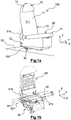
- the figure 1a illustrates an example of a seat 100 according to the invention in the seated position.
- a conventional axis system linked to the seat, with a longitudinal axis X, horizontal oriented positively towards the front of the seat, a vertical axis Z, oriented positively upwards, and a lateral axis Y, perpendicular to a plane defined by the horizontal and vertical directions, oriented positively to the left of the seat.
- front, rear, top down and similar terms or expressions relating to the directions or directions refer to the positions, directions or directions which would be given to them by a user of the seat while seated in said seat.
- front of the seat corresponds to the direction towards which the occupant seated in the seat looks, without turning their head, regardless of the orientation that the seat can have with respect to the direction of movement of a vehicle in which it is installed.
- the seat of the figure 1 comprises a seat 20 and a backrest 10.
- the seat is here simplified and stripped of accessories not necessary for the presentation of the invention or for its understanding, for example armrests, which may or may not be present on a seat of the invention.
- the seat also has a structure 30, partially visible on the figure 1a , which in the seat is covered by mattresses, seat mattress 21 and back mattress 11, and covering panels 12 for reasons of comfort, aesthetics and security.
- the figure 1b illustrates the seat shown on the figure 1a devoid of mattresses and covering panels so as to leave the structure 30 visible.
- the structure is partial in that certain elements which are not useful for the presentation of the invention are not shown, for example said structure is shown without detail of the headrest, leg rest, lumbar support, armrest, movement locking systems ...
- the structure which provides the seat with strength and rigidity to support the weight of an occupant under all conditions of use of said seat, allows the forces to be transmitted to another structure which must carry the seat, for example a floor 32 of vehicle to which the seat is attached.
- the base structure may be designated “base”
- the seat structure may be designated “seat”
- the back structure may be designated “file”
- the skilled person being able to determine whether it should be understood, in a given context, whether the term relates to the structure of a subset or to the complete subset.
- the term “seat” will designate the complete seat, with the seat structure, the mattresses and any other accessories associated with the seat, as shown schematically on the figure 1a or the seat structure, for example as shown schematically on the figure 1b .
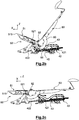
- the figure 2a shows, simplified, the structure of the figure 1b in profile view.
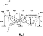
- the base 40 comprises two flanges 41 arranged laterally and symmetrically on lateral edges of the base, only one of which is visible in the profile view of the figure 2a and of which an exemplary embodiment, isolated from the rest of the structure, is represented on the figure 3 .
- Each flange 41 is formed mainly of a plate 44 adapted to support components of the base and to transmit the forces from the seat to the floor 32 or another structure on which the seat is fixed.
- Each flange also supports a guide ramp 43 according to a double S profile, having a low point in a middle part of said guide ramp, intended to guide the movement of a rear roller 54 of seat and whose operation details will be described later.
- the four segments thus defined are connected by curved connecting segments so as to ensure the continuity of the guide ramp and to define a path 431 followed by the rear roller 54 between the rear 436 and front 437 ends.
- each of the rear, rear intermediate, front intermediate and front segments is substantially rectilinear.
- the rear segment 432 and the front segment 435 are substantially horizontal.
- the rear intermediate segment 433 has a downward slope forwards and the front intermediate segment 434 has a rising slope forwards so as to determine at their junction a low point 438 of the path 431 determined by the guide ramp 43 for the rear roller 54.
- the rear end 436 is situated at a height Har with respect to a horizontal reference plane, for example the plane of the floor 32 when the seat is fixed on a floor, the front end 437 is at a height Hav with respect to the horizontal reference plane, and the low point 438 is at a height Hmin less than the rear heights 436 and front 437.
- the guide ramps 43 supported by each of the lateral flanges 41 are symmetrical to one another with respect to a vertical axial plane XZ of vertical symmetry of the entire seat and each determines a trajectory 431 of the rear roller 54 of the seat moving in a vertical plane.
- each guide ramp is made integrally with the flange which supports it.
- Each flange 41 also supports a slide 42, in the illustrated form a system of telescopic rails comprising a fixed rail 421 on which slides a sliding rail 422.
- the two telescopic rails are here rectilinear rails.
- the fixed rail 421, fixed on the flange 41, is held in a vertical longitudinal plane XZ and with a slope inclined towards the front of the seat relative to the horizontal direction X.
- the sliding rail 422 slides relative to the fixed rail 421 between a retracted position and a relaxed position in which said sliding rail is advanced relative to the retracted position.
- the seat 50 includes a seat plate 51, illustrated in partial exploded view on the figure 1c , constituting a support structure for the seat mattress 21, and comprising longitudinal beams 511a, 511b supporting upper panels 512, 513.
- the seat plate 51 is held integral with the base 40 by rear seat rollers 54 and by front carriages 52 of the seat.
- the seat rollers are not visible and only one front seat carriage is visible.
- the arrangement of the rollers on the one hand and the carriages on the other hand are symmetrical with respect to the vertical axial plane XZ of overall symmetry of the seat.
- Each front seat carriage 52 is articulated on the seat plate about a tilting axis 521 of the seat parallel to the lateral axis Y so that the seat plate 51 is able to take an inclination more or less inclined backwards or forwards around said tilting axis.
- the tilting axis 521 is located between a rear edge 514 and a front edge 515 of the seat so that during a tilting of the seat plate 51 about the axis towards the rear. tilting 521, the front edge 515 moves upwards and the rear edge 514 downwards, and conversely the front edge downwards and the rear edge upwards when the seat plate swings forward.
- Each seat carriage 52 is also rigidly fixed to the corresponding sliding rail 422 so that the sliding of said sliding rail relative to the fixed rail 421 makes it possible to move, in a direction determined by the orientation of said fixed rail, said seat carriage and therefore the tilting axis 521 and the seat plate 51.
- Each rear roller 54 is fixed to the seat plate 51 in a rear part of said seat plate, near the rear edge 514 of said seat plate, with a rear axis 541 parallel to the lateral axis Y.
- Each rear roller 54 is further engaged in the corresponding guide ramp 43 so as to follow the path 431 determined by said ramp when the seat 50, and therefore also said rear roller, is moved in the longitudinal direction X relative to the '' base 40.
- the backrest 60 is articulated on the seat 50 around a hinge pin 62 fixed relative to the seat plate 51 and fixed relative to the backrest 60.
- the rotation of the backrest 60 is limited towards the front by stops 64 of the seat plate which cooperate with first stop surfaces 65, figure 2a .
- the seat 50 is located at the rear of the base 40.
- the rear seat rollers 54 are located at the rear ends 436 of the guide ramps 43, or at least close to said rear ends of the ramps of guide, at rear height Har.
- the backrest 60 is in this case illustrated in its most raised position with the stop 64 against the first stop surface 65.
- a backward inclination of the backrest 60 is possible in this case without movement of the seat 50, even if it is likely to be limited in practice by the headquarters environment.
- the figure 2c shows the structure of the seat when the seat is adjusted in the "lying" position, that is to say to form a substantially horizontal bed.
- the seat and the backrest are aligned and both substantially horizontal, this arrangement being able to be slightly different to compensate for thicknesses and shapes of seat mattress 21 and back mattress 11 which would not be identical or regular.
- the seat 50 is advanced relative to the base 40 in a position in which the rear seat rollers 54 are located at the front ends 437 of the guide rails 43, or at least close to said front ends of the guide rails, at the height before Hav.
- the forward movement of the seat 50 is obtained with the forward extension of the sliding rail 422 which holds and guides the front seat carriage 52.
- This forward movement is accompanied by a modification of the height of the tilting axis 521, on which the seat plate 51 is articulated, which is a function of the inclination of the fixed rail 421.
- the height of said tilting axis relative to the horizontal plane of reference decreases due to the forward tilt of the fixed rail 421.
- the resulting height of the tilting axis 521 and the front height Hav of the guide ramps are determined in this "lying" position so that the seat is in the substantially horizontal position desired.
- the backrest is inclined backwards relative to the seat until the abutments 64 come into contact with the second stop surfaces 66.
- the seat 50 is advanced relative to the base 40 in a position in the longitudinal direction X intermediate between those of the “seated” positions of the figure 2a and “lying" of the figure 2c .
- the tilting axis 521 is also at a height reduced relative to its height in the "seated" position, due to the slope of the fixed rails 421, but this reduction in height is substantially lower than that of the rear seat rollers due to the accentuated concave shape of the paths 431 determined by the segments of the guide ramps 43.
- the seat plate 51 is tilted backwards around the tilting axis 521, by lowering the rear 514 of the seat, close to the rear seat rollers.
- a height of the front edge 515 of the seat is not increased by this rearward tilting, or is only increased by a limited height, due to the lowering of the front carriages 52 of the seat. fixed to the sliding rails 422 whose trajectory descends towards the front.
- the movement of the seat 50 in the longitudinal direction X is preferably carried out by a single actuator, not shown, for example a conventional electric actuator.
- the movement of the backrest articulated on the seat about the hinge axis 62 is produced by a backrest actuator, not shown, so that the backrest can be tilted to different values for each longitudinal position of the seat, within limits of interference with surrounding structures.
- the seat 50 is in a retracted position relative to the base 40 in which the rear seat rollers 54 are located at the rear ends 436 of the guide ramps 43, at least close to said rear ends.
- the seat carriages 52 fixed to the sliding rails 422, are also in the retracted position.
- the seat rollers are at the rear height Har of the guide rails 43 and the tilting axis 521 is at a maximum height on the inclined ramps formed by the slides 42.
- the geometric and dimensional parameters are chosen during the design of the seat to determine, in this rear position of the seat, a height of said seat relative to the floor, height generally considered at a SRP reference point of the seat, and a longitudinal inclination of the seat relative to a horizontal plane adapted to the comfort of the "seated" position.
- the seat has a longitudinal inclination towards the rear at an angle to the horizontal of between 5 and 15 degrees which allows a seat user to feel secure and stable in his seat.
- a height of a front edge of the seat 20, comprising its seat mattress 21, is determined so that a passenger from a target population taken as a reference can put their feet flat on the floor, or on a rest feet, when seated in the seat.
- the backrest is preferably straightened to form an angle of 90 degrees with the seat, an angle which can however be more open, either by building the seat a few degrees to be between 90 and 100 degrees. , or by backrest adjustment capabilities leaving the user the possibility of tilting the backrest more or less relative to the seat.
- the position of the seat in particular of the seat subjected in use to the weight of the occupant acting essentially vertically, is naturally stable because the rear rollers are located in the rear segments of the substantially horizontal guide rails. In this position, the actuator and or the seat blocking means are therefore moderately stressed to prevent an unsolicited horizontal translation of the seat.
- each rear roller 54 of the seat will move in the corresponding guide ramp 43, in firstly by following the rear segment 432 of said guide ramp, and each front seat carriage 52 will follow a downward-sloping trajectory determined by the corresponding slide 42.
- the angle of the seat relative to the horizontal will be a function of the difference in inclination between said rear segments and the slides.
- the rear segments 432 are substantially horizontal, in practice with an angle of inclination relative to a horizontal plane comprised between the angle corresponding to the value of the angle of forward inclination slides 42 and an angle, considered from the rear to the front, raised above the horizontal plane by 10 degrees.
- a raised angle of 8 degrees provides a movement to assist in the transition to the standing position for the seat occupant without the one needing special attention to remain seated when he makes a transition between the position "Sit" and the "rest” position.
- the inclination of the seat is kept constant during movement. This movement, if stopped when the rear seat rollers are still in the rear segments, allows the seat occupant to increase the inclination of his backrest which is far from obstacles which may limit this tilt.
- the seat plate swings progressively forward around the tilting axis 521 when said seat moves forward.
- the amplitude of this forward tilting is of course a function of the angle between the rear segments and the slides and of a distance on the seat plate 51 between the rear axis 541 and the tilting axis 521 .
- This angular movement of the seat plate which is accompanied by a reduction in the height of the front edge of the seat, and a reduction in the inclination of the backrest towards the rear relative to the vertical direction, allows a seat user to get into an attitude closer to the vertical position and facilitates, in particular for a person having difficulty getting out of a seat after having been seated for a long time, switching to a standing position with a reduced effort.
- each rear seat roller 54 When the forward movement of the seat is continued, each rear seat roller 54 then travels through the corresponding rear intermediate segment 433 along a downward path to the low point 438.
- the front carriages 52 of the seat are also advanced on the runners 42 leading to a lowering of the tilting axis 521 of the seat.
- the downward slope of the rear intermediate segment 433 is greater than the downward slope of the slide 42 leading to a relative lowering of the rear seat roller 54, and therefore of the rear edge of the seat 514 substantially at the junction between the seat and backrest, with respect to the tilting axis 521 of seat.
- the seat plate is therefore, in this longitudinal position of the seat, tilted backwards with respect to the previous situation, as illustrated in the figure 2b in the "rest" position.
- the backrest 60 is placed in a position to form with the seat an angle more open than in the "seated” position, typically an angle between 100 and 115 degrees.
- the overall shape of the seat resulting from the movements of the seat and the back corresponds to a bucket whose inclination towards the rear is marked to determine in profile a hollow shape which gives the occupant of the seat great stability and prevents it from sliding forward of the seat, even in the event of movements of the floor 32, for example due to turbulence encountered by an airplane in flight.
- the overall lowering of the seat plate associated with its tilting towards the rear avoids a rise in the front edge 515 of the seat, or at least limits an amplitude of this rise.
- the seat occupant can thus keep their feet on the floor with the seat in the "rest” position, or on the footrest associated with the seat, as in the "seated” position.
- This configuration therefore makes it possible to maintain the comfort of the occupant over a long period by avoiding causing compression of the legs at the popliteal recess of said occupant.
- each rear seat roller 54 then travels through the corresponding front intermediate segment 434 along an upward trajectory from the low point 438 which continues on the front segment 435 substantially horizontal up to 'at the front end 437 of the guide ramp, or at least near said front end.
- the front carriages 52 of the seat are also advanced on the runners 42 leading to a further lowering of the seat tilting axis 521.
- the seat In this longitudinal position of the seat 50, the seat is substantially horizontal in the desired position in the "lying" position.
- This substantially horizontal position is obtained by a choice of the height Hav of the front end 437 of the guide ramp relative to the height position of the front seat carriages 52, choice resulting from a geometric construction during design of the guide rail 43.
- the backrest 60 is inclined backwards to be substantially aligned with the seat 50 in order to form a sleeping plane. This backrest tilt is possible without interference with structures behind the seat due to the forward movement of the seat.
- the seat and the seat in this “lying” position of the seat, the seat and the seat, subjected in use to the weight of the occupant exercising essentially vertically, is naturally stable because the rollers rear are located in the front segments of the substantially horizontal guide rails. In this position, the actuator and or the seat blocking means are therefore also moderately stressed to prevent an unsolicited horizontal translation of the seat.
- the three positions "sitting", “rest” and “lying”, intended for prolonged maintenance in use are mechanically stable which results in reduced stresses of the actuator and or means for blocking the movements of the seat and therefore an improvement in the reliability of the components used.
Landscapes
- Engineering & Computer Science (AREA)
- Aviation & Aerospace Engineering (AREA)
- Transportation (AREA)
- Mechanical Engineering (AREA)
- Seats For Vehicles (AREA)
- Health & Medical Sciences (AREA)
- General Health & Medical Sciences (AREA)
- Nursing (AREA)
- Chairs For Special Purposes, Such As Reclining Chairs (AREA)
Claims (14)
- Sitz (100) für Passagier eines Fahrzeugs, umfassend eine Sitzfläche (20) und eine Lehne (10), wobei eine Sitzflächenstruktur (50) mit einer Basisplatte (40) solidarisch ist, über die der Sitz an dem Fahrzeug befestigt werden kann, wobei der Sitz wenigstens eine "sitzende" Position, eine "liegende" Position und wenigstens eine "ruhende" Position umfasst, intermediär zwischen der "sitzenden" Position und der "liegenden" Position, in welchem:- eine Sitzflächenebene (51) der Sitzflächenstruktur (50) in Rotation um eine hintere Achse (541) der Sitzfläche mobil ist, ausgerichtet gemäß einer querverlaufenden horizontalen Richtung Y des Sitzes und senkrecht zu einer vertikalen Symmetrieebene XZ der Gesamtheit des Sitzes, wobei die hintere Achse gemäß einer längsverlaufenden Richtung X des Sitzes der Seite einer hinteren Kante (514) der Sitzfläche positioniert ist;- die Sitzflächenebene (51) in Rotation um eine Kippachse (521) mobil ist, fix in Bezug auf die Sitzflächenstruktur (50), parallel zu der hinteren Achse (541), positioniert gemäß der längsverlaufenden Richtung X, vor der hinteren Achse und zwischen der hinteren Kante (514) der Sitzfläche und einer vorderen Kante (515) der Sitzfläche;- die Sitzflächenstruktur (50) bei einer Konversion des Sitzes von der "sitzenden" Position in die "liegende" Position nach vorne deplatziert wird, wobei während der Konversion:+ die Kippachse (521) auf der Basisplatte (40) gemäß einer ersten in Bezug auf die längsverlaufende horizontale Richtung X abfallenden Bahn deplatziert wird;+ die hintere Achse (541) auf der Basisplatte gemäß einer zweiten durchgehenden Bahn (431) deplatziert wird, nacheinander gemäß der Richtung der Deplatzierung der Sitzfläche nach vorne Folgendes umfassend:- ein hinteres Segment (432), im Wesentlichen horizontal;- ein intermediäres hinteres Segment (433), eine absteigende Neigung aufweisend größer als eine von der Kippachse (521) verfolgte Neigung;- ein intermediäres vorderes Segment (434) mit einer steigenden Neigung;- ein im Wesentlichen horizontales vorderes Segment (435).
- Sitz nach Anspruch 1, in welchem die Kippachse (521) von wenigstens einem Schlitten (52) getragen wird, wobei der Schlitten auf einer Schiene (42) der Basisplatte (40) montiert ist, eine Führung des Schlittens gemäß der ersten Bahn gewährleistend, wenn die Sitzflächenstruktur (50) in einer längsverlaufenden Richtung deplatziert wird.
- Sitz nach Anspruch 1 oder Anspruch 2, in welchem die zweite Bahn (431) gefolgt von der hinteren Achse (541) bestimmt wird durch wenigstens eine Führungsrampe (43) der Basisplatte, wobei in der Führungsrampe wenigstens eine Rolle (54) oder eine Kufe der Sitzfläche in einer längsverlaufenden Richtung zirkuliert, wenn die Sitzflächenstruktur (50) in eine längsverlaufende Richtung deplatziert wird, wobei eine Achse der Rolle oder eines Lagers der Kufe die hintere Achse (541) bestimmt.
- Sitz nach einem der Ansprüche 1, 2 oder 3, in welchem das intermediäre hintere Segment (433) und das intermediäre vordere Segment (434) an ihrer Verbindungsstelle einen Tiefpunkt (438) bestimmen mit einer Höhe Hmin gemäß einer vertikalen Richtung Z in Bezug auf eine horizontale Referenzebene der zweiten Bahn (431), wobei an dem Tiefpunkt die hintere Achse positioniert ist, wenn sich der Sitz in der "ruhenden" Position befindet, wobei die Höhe Hmin in Anbetracht der dimensionalen Eigenschaften der Sitzflächenstruktur (50) und der Basisplatte (40), wenn sich der Sitz in der "ruhenden" Position befindet, folgendermaßen beschaffen ist:- die Sitzflächenebene (51) wird in Bezug auf die Position der Sitzflächenebene in die "sitzende" Position des Sitzes nach hinten gekippt;- eine resultierende Höhe in Bezug auf die Referenzebene einer vorderen Kante der Sitzfläche (20) befindet sich im Wesentlichen auf der Höhe der vorderen Kante der Sitzfläche, wenn sich der Sitz in der "sitzenden" Position befindet.
- Sitz nach einem der vorhergehenden Ansprüche, in welchen die Sitzfläche horizontal oder nach vorne geneigt ist, wenn sich die hintere Achse (541) an einer Verbindungsstelle des hinteren Segments (432) und des intermediären hinteren Segments (433) befindet.
- Sitz nach einem der vorhergehenden Ansprüche, in welchem das im Wesentlichen horizontale hintere Segment (432), von hinten nach vorne betrachtet, nach unten geneigt ist höchstens mit einem Winkel entsprechend einem Winkel der ersten abfallenden Bahn, und nach oben geneigt ist mit einem Winkel von höchstens 10 Grad in Bezug auf eine horizontale Referenzebene, typischerweise mit einem Winkel von null Grad.
- Sitz nach einem der vorhergehenden Ansprüche, in welchem, wenn sich der Sitz in der "sitzenden" Position befindet, die Sitzfläche nach hinten geneigt ist mit einem Winkel in Bezug auf eine horizontale Referenzebene zwischen 5 und 15 Grad, typischerweise ungefähr 10 Grad.
- Sitz nach einem der vorhergehenden Ansprüche, in welchem, wenn sich der Sitz in der "ruhenden" Position befindet, die Sitzfläche nach hinten geneigt ist mit einem Winkel in Bezug auf eine horizontale Referenzebene zwischen 18 und 30 Grad, typischerweise ungefähr 22 Grad.
- Sitz nach einem der vorhergehenden Ansprüche, in welchem, wenn sich der Sitz in der "liegenden" Position befindet, die Sitzfläche im Wesentlichen horizontal ist oder in Bezug auf eine horizontale Referenzebene geneigt ist mit einem Winkel kleiner als oder gleich 5 Grad als absoluten Wert.
- Sitz nach einem der vorhergehenden Ansprüche, in welchem jede Schiene (42) der Basisplatte nach vorne geneigt ist mit einem Winkel zwischen 2 und 8 Grad in Bezug auf eine horizontale Referenzebene, typischerweise ungefähr 5 Grad.
- Sitz nach einem der vorhergehenden Ansprüche in Kombination mit Anspruch 2 und Anspruch 3, umfassend zwei Schienen (42) der Basisplatte, zwei die Sitzflächenebene (51) stützende Schlitten (52), zwei fixe Führungsrampen (43) der Basisplatte, wobei die zwei Schienen, die zwei Schlitten und die zwei Führungsrampen in Bezug auf die vertikale Symmetrieebene XZ der Gesamtheit des Sitzes im Wesentlichen symmetrisch sind.
- Sitz nach einem der vorhergehenden Ansprüche, in welchem eine Lehnenstruktur (60) auf der Sitzflächenstruktur (50) um eine Scharnierachse (62) parallel zu der querverlaufenden Richtung Y artikuliert ist, platziert in der Nähe einer hinteren Kante (514) der Sitzflächenstruktur, solcherart, dass sie einen Winkel zwischen dem Sitzfläche und der Lehne bestimmt, verstellbar bei Verwendung des Sitzes zwischen einem minimalen Wert im Wesentlichen gleich 90 Grad, angepasst an die "sitzende" Position, und einen maximalen Wert im Wesentlichen gleich 180 Grad, angepasst an die "liegende" Position.
- Sitz nach Anspruch 12, umfassend wenigstens einen Anschlag (64) der Basisplatte (40) kooperierend mit einer ersten Arretierfläche (65) der Lehnenstruktur (60) zum Eingrenzen der winkelförmigen Deplatzierung der Lehne nach vorne und kooperierend mit einer zweiten Arretierfläche (66) der Lehnenstruktur zum Beschränken der winkelförmigen Deplatzierung der Lehne nach hinten.
- Sitz nach einem der vorhergehenden Ansprüche, in welchem die Deplatzierung der Sitzfläche zwischen der "sitzenden" Position und der "liegenden" Position durch ein einziges Stellglied gewährleistet wird.
Applications Claiming Priority (1)
| Application Number | Priority Date | Filing Date | Title |
|---|---|---|---|
| FR1752932A FR3064556A1 (fr) | 2017-04-04 | 2017-04-04 | Fauteuil pour passager de vehicule comportant une configuration repos |
Publications (2)
| Publication Number | Publication Date |
|---|---|
| EP3385115A1 EP3385115A1 (de) | 2018-10-10 |
| EP3385115B1 true EP3385115B1 (de) | 2020-06-10 |
Family
ID=59031170
Family Applications (1)
| Application Number | Title | Priority Date | Filing Date |
|---|---|---|---|
| EP18165510.1A Active EP3385115B1 (de) | 2017-04-04 | 2018-04-03 | Sessel für passagier eines fahrzeugs mit ruhekonfiguration |
Country Status (5)
| Country | Link |
|---|---|
| US (1) | US10486814B2 (de) |
| EP (1) | EP3385115B1 (de) |
| JP (1) | JP2018197101A (de) |
| BR (1) | BR102018006797A2 (de) |
| FR (1) | FR3064556A1 (de) |
Cited By (1)
| Publication number | Priority date | Publication date | Assignee | Title |
|---|---|---|---|---|
| US11401038B1 (en) | 2021-06-07 | 2022-08-02 | B/E Aerospace, Inc. | Aircraft seat |
Families Citing this family (7)
| Publication number | Priority date | Publication date | Assignee | Title |
|---|---|---|---|---|
| EP3374264B1 (de) * | 2015-11-10 | 2022-01-05 | Safran Seats | Flugzeugsitz für crew |
| DE102019204488B4 (de) * | 2019-03-29 | 2023-05-04 | Adient Aerospace, Llc | Sitz, insbesondere Flugzeugsitz |
| GB2586143B (en) * | 2019-08-07 | 2022-12-28 | Safran Seats Gb Ltd | Aircraft Seat and Mechanism for seat actuation |
| FR3123322B1 (fr) * | 2021-05-28 | 2024-06-28 | Safran Seats | Assise de siege, notamment de siege d'avion, munie d'un tube absorbeur d'energie cinetique |
| FR3123321B1 (fr) | 2021-05-28 | 2024-06-28 | Safran Seats | Assise de siege, notamment de siege d'avion, munie d'une zone de degagement pour le bassin |
| KR102748254B1 (ko) * | 2022-05-12 | 2024-12-31 | 대원산업 주식회사 | 연동형 릴렉스 시트 장치 |
| FR3153330A1 (fr) * | 2023-09-26 | 2025-03-28 | Dassault Aviation | Structure de siège d'aéronef inclinable, et cabine d'aéronef associée |
Family Cites Families (7)
| Publication number | Priority date | Publication date | Assignee | Title |
|---|---|---|---|---|
| US3202453A (en) * | 1963-07-09 | 1965-08-24 | Ford Motor Co | Retractable seat |
| US3171682A (en) * | 1963-09-23 | 1965-03-02 | Gen Motors Corp | Folding vehicle seats |
| GB9425078D0 (en) * | 1994-12-13 | 1995-02-08 | British Airways Plc | A seating unit |
| GB0706775D0 (en) * | 2007-04-05 | 2007-05-16 | Premium Aircraft Interiors Uk | Aircraft seat |
| US8403415B2 (en) * | 2010-08-16 | 2013-03-26 | Be Aerospace, Inc. | Aircraft passenger seat recline mechanism |
| BE1020730A3 (nl) * | 2013-02-04 | 2014-04-01 | Hool Nv Van | Inrichting van een zitrijtuig en verstelbare zetel hiervoor. |
| CN105916768B (zh) * | 2013-12-27 | 2019-06-28 | 庞巴迪公司 | 可转换成床的飞机长沙发椅 |
-
2017
- 2017-04-04 FR FR1752932A patent/FR3064556A1/fr not_active Ceased
-
2018
- 2018-04-03 JP JP2018071329A patent/JP2018197101A/ja active Pending
- 2018-04-03 US US15/943,922 patent/US10486814B2/en active Active
- 2018-04-03 EP EP18165510.1A patent/EP3385115B1/de active Active
- 2018-04-04 BR BR102018006797-4A patent/BR102018006797A2/pt not_active Application Discontinuation
Non-Patent Citations (1)
| Title |
|---|
| None * |
Cited By (1)
| Publication number | Priority date | Publication date | Assignee | Title |
|---|---|---|---|---|
| US11401038B1 (en) | 2021-06-07 | 2022-08-02 | B/E Aerospace, Inc. | Aircraft seat |
Also Published As
| Publication number | Publication date |
|---|---|
| US20180362165A1 (en) | 2018-12-20 |
| EP3385115A1 (de) | 2018-10-10 |
| FR3064556A1 (fr) | 2018-10-05 |
| US10486814B2 (en) | 2019-11-26 |
| BR102018006797A2 (pt) | 2019-03-19 |
| JP2018197101A (ja) | 2018-12-13 |
Similar Documents
| Publication | Publication Date | Title |
|---|---|---|
| EP3385115B1 (de) | Sessel für passagier eines fahrzeugs mit ruhekonfiguration | |
| EP2878481B1 (de) | Passagiersitz mit Schalensitzstruktur und einstellbarer Position | |
| EP2998222B1 (de) | Multipositionssitz für fahrzeugbediener | |
| EP1345810B1 (de) | In ein bett umwandelbarer sitz, insbesondere für ein flugzeug | |
| FR2820400A1 (fr) | Siege multipositions pour avion | |
| CN111297107A (zh) | 自动适应腰部的座椅 | |
| WO2013167822A1 (fr) | Siege articule dote d'un mouvement synchrone ente l'assise et le dossier | |
| EP0274330A1 (de) | Aufricht- und Sitzvorrichtung mit besonderer Anwendung auf Sessel, Stühle oder feste oder bewegliche Sitze | |
| FR2462323A1 (fr) | Perfectionnements aux voitures d'enfant notamment du type a siege permettant une pluralite de positions | |
| FR2965716A1 (fr) | Fauteuil roulant equipe d'au moins un accoudoir | |
| EP3594049A1 (de) | Sesseleinheit, die ein bewegliches sitzflächen-ausziehelement umfasst | |
| FR3049577B1 (fr) | Siege convertible en couchage elargi | |
| FR3115267A1 (fr) | Amenagement interieur d'une cabine d'aeronef et procede associe | |
| EP4532324A1 (de) | Sitzeinheit für einen fluggast mit aufnahmeposition | |
| EP1483987B1 (de) | Ruhestuhl mit einem flexiblen Element zur Unterstützung eines Benutzers das von einer Rückenlehne und einem Sitz getragt ist, welche zusammen angelenkt sind und die an einem Rahmen verschiebbar gelagert sind | |
| WO2002047513A1 (fr) | Fauteuil multi-positions | |
| FR2513499A1 (fr) | Perfectionnement apporte a un siege permettant de changer de position (debout, assis, allonge) sans depense d'efforts physiques | |
| FR3074109A1 (fr) | Siege de vehicule au confort ameliore | |
| FR2976872A1 (fr) | Siege reglable de vehicule | |
| EP2441424B1 (de) | Mit einer Fußstütze ausgestatteter Rollstuhl | |
| EP4530187A1 (de) | Flugzeugsitzstruktur mit konischer basis und flugzeugkabine | |
| EP4530188A1 (de) | Kippbare flugzeugsitzstruktur und flugzeugkabine damit | |
| WO1988000035A1 (fr) | Fauteil inclinable | |
| EP4424598A1 (de) | Manuell umwandelbarer sitz für flugzeugpassagiere | |
| FR3074106A1 (fr) | Siege de vehicule au confort ameliore |
Legal Events
| Date | Code | Title | Description |
|---|---|---|---|
| PUAI | Public reference made under article 153(3) epc to a published international application that has entered the european phase |
Free format text: ORIGINAL CODE: 0009012 |
|
| STAA | Information on the status of an ep patent application or granted ep patent |
Free format text: STATUS: THE APPLICATION HAS BEEN PUBLISHED |
|
| AK | Designated contracting states |
Kind code of ref document: A1 Designated state(s): AL AT BE BG CH CY CZ DE DK EE ES FI FR GB GR HR HU IE IS IT LI LT LU LV MC MK MT NL NO PL PT RO RS SE SI SK SM TR |
|
| AX | Request for extension of the european patent |
Extension state: BA ME |
|
| STAA | Information on the status of an ep patent application or granted ep patent |
Free format text: STATUS: REQUEST FOR EXAMINATION WAS MADE |
|
| 17P | Request for examination filed |
Effective date: 20190409 |
|
| RBV | Designated contracting states (corrected) |
Designated state(s): AL AT BE BG CH CY CZ DE DK EE ES FI FR GB GR HR HU IE IS IT LI LT LU LV MC MK MT NL NO PL PT RO RS SE SI SK SM TR |
|
| GRAP | Despatch of communication of intention to grant a patent |
Free format text: ORIGINAL CODE: EPIDOSNIGR1 |
|
| STAA | Information on the status of an ep patent application or granted ep patent |
Free format text: STATUS: GRANT OF PATENT IS INTENDED |
|
| INTG | Intention to grant announced |
Effective date: 20200129 |
|
| GRAS | Grant fee paid |
Free format text: ORIGINAL CODE: EPIDOSNIGR3 |
|
| GRAA | (expected) grant |
Free format text: ORIGINAL CODE: 0009210 |
|
| STAA | Information on the status of an ep patent application or granted ep patent |
Free format text: STATUS: THE PATENT HAS BEEN GRANTED |
|
| AK | Designated contracting states |
Kind code of ref document: B1 Designated state(s): AL AT BE BG CH CY CZ DE DK EE ES FI FR GB GR HR HU IE IS IT LI LT LU LV MC MK MT NL NO PL PT RO RS SE SI SK SM TR |
|
| REG | Reference to a national code |
Ref country code: GB Ref legal event code: FG4D Free format text: NOT ENGLISH |
|
| REG | Reference to a national code |
Ref country code: CH Ref legal event code: EP Ref country code: AT Ref legal event code: REF Ref document number: 1278918 Country of ref document: AT Kind code of ref document: T Effective date: 20200615 |
|
| REG | Reference to a national code |
Ref country code: DE Ref legal event code: R096 Ref document number: 602018005128 Country of ref document: DE |
|
| REG | Reference to a national code |
Ref country code: IE Ref legal event code: FG4D Free format text: LANGUAGE OF EP DOCUMENT: FRENCH |
|
| REG | Reference to a national code |
Ref country code: LT Ref legal event code: MG4D |
|
| PG25 | Lapsed in a contracting state [announced via postgrant information from national office to epo] |
Ref country code: LT Free format text: LAPSE BECAUSE OF FAILURE TO SUBMIT A TRANSLATION OF THE DESCRIPTION OR TO PAY THE FEE WITHIN THE PRESCRIBED TIME-LIMIT Effective date: 20200610 Ref country code: SE Free format text: LAPSE BECAUSE OF FAILURE TO SUBMIT A TRANSLATION OF THE DESCRIPTION OR TO PAY THE FEE WITHIN THE PRESCRIBED TIME-LIMIT Effective date: 20200610 Ref country code: FI Free format text: LAPSE BECAUSE OF FAILURE TO SUBMIT A TRANSLATION OF THE DESCRIPTION OR TO PAY THE FEE WITHIN THE PRESCRIBED TIME-LIMIT Effective date: 20200610 Ref country code: NO Free format text: LAPSE BECAUSE OF FAILURE TO SUBMIT A TRANSLATION OF THE DESCRIPTION OR TO PAY THE FEE WITHIN THE PRESCRIBED TIME-LIMIT Effective date: 20200910 Ref country code: GR Free format text: LAPSE BECAUSE OF FAILURE TO SUBMIT A TRANSLATION OF THE DESCRIPTION OR TO PAY THE FEE WITHIN THE PRESCRIBED TIME-LIMIT Effective date: 20200911 |
|
| REG | Reference to a national code |
Ref country code: NL Ref legal event code: MP Effective date: 20200610 |
|
| PG25 | Lapsed in a contracting state [announced via postgrant information from national office to epo] |
Ref country code: LV Free format text: LAPSE BECAUSE OF FAILURE TO SUBMIT A TRANSLATION OF THE DESCRIPTION OR TO PAY THE FEE WITHIN THE PRESCRIBED TIME-LIMIT Effective date: 20200610 Ref country code: RS Free format text: LAPSE BECAUSE OF FAILURE TO SUBMIT A TRANSLATION OF THE DESCRIPTION OR TO PAY THE FEE WITHIN THE PRESCRIBED TIME-LIMIT Effective date: 20200610 Ref country code: BG Free format text: LAPSE BECAUSE OF FAILURE TO SUBMIT A TRANSLATION OF THE DESCRIPTION OR TO PAY THE FEE WITHIN THE PRESCRIBED TIME-LIMIT Effective date: 20200910 Ref country code: HR Free format text: LAPSE BECAUSE OF FAILURE TO SUBMIT A TRANSLATION OF THE DESCRIPTION OR TO PAY THE FEE WITHIN THE PRESCRIBED TIME-LIMIT Effective date: 20200610 |
|
| REG | Reference to a national code |
Ref country code: AT Ref legal event code: MK05 Ref document number: 1278918 Country of ref document: AT Kind code of ref document: T Effective date: 20200610 |
|
| PG25 | Lapsed in a contracting state [announced via postgrant information from national office to epo] |
Ref country code: NL Free format text: LAPSE BECAUSE OF FAILURE TO SUBMIT A TRANSLATION OF THE DESCRIPTION OR TO PAY THE FEE WITHIN THE PRESCRIBED TIME-LIMIT Effective date: 20200610 Ref country code: AL Free format text: LAPSE BECAUSE OF FAILURE TO SUBMIT A TRANSLATION OF THE DESCRIPTION OR TO PAY THE FEE WITHIN THE PRESCRIBED TIME-LIMIT Effective date: 20200610 |
|
| PG25 | Lapsed in a contracting state [announced via postgrant information from national office to epo] |
Ref country code: CZ Free format text: LAPSE BECAUSE OF FAILURE TO SUBMIT A TRANSLATION OF THE DESCRIPTION OR TO PAY THE FEE WITHIN THE PRESCRIBED TIME-LIMIT Effective date: 20200610 Ref country code: RO Free format text: LAPSE BECAUSE OF FAILURE TO SUBMIT A TRANSLATION OF THE DESCRIPTION OR TO PAY THE FEE WITHIN THE PRESCRIBED TIME-LIMIT Effective date: 20200610 Ref country code: SM Free format text: LAPSE BECAUSE OF FAILURE TO SUBMIT A TRANSLATION OF THE DESCRIPTION OR TO PAY THE FEE WITHIN THE PRESCRIBED TIME-LIMIT Effective date: 20200610 Ref country code: EE Free format text: LAPSE BECAUSE OF FAILURE TO SUBMIT A TRANSLATION OF THE DESCRIPTION OR TO PAY THE FEE WITHIN THE PRESCRIBED TIME-LIMIT Effective date: 20200610 Ref country code: AT Free format text: LAPSE BECAUSE OF FAILURE TO SUBMIT A TRANSLATION OF THE DESCRIPTION OR TO PAY THE FEE WITHIN THE PRESCRIBED TIME-LIMIT Effective date: 20200610 Ref country code: ES Free format text: LAPSE BECAUSE OF FAILURE TO SUBMIT A TRANSLATION OF THE DESCRIPTION OR TO PAY THE FEE WITHIN THE PRESCRIBED TIME-LIMIT Effective date: 20200610 Ref country code: PT Free format text: LAPSE BECAUSE OF FAILURE TO SUBMIT A TRANSLATION OF THE DESCRIPTION OR TO PAY THE FEE WITHIN THE PRESCRIBED TIME-LIMIT Effective date: 20201012 |
|
| PG25 | Lapsed in a contracting state [announced via postgrant information from national office to epo] |
Ref country code: PL Free format text: LAPSE BECAUSE OF FAILURE TO SUBMIT A TRANSLATION OF THE DESCRIPTION OR TO PAY THE FEE WITHIN THE PRESCRIBED TIME-LIMIT Effective date: 20200610 Ref country code: SK Free format text: LAPSE BECAUSE OF FAILURE TO SUBMIT A TRANSLATION OF THE DESCRIPTION OR TO PAY THE FEE WITHIN THE PRESCRIBED TIME-LIMIT Effective date: 20200610 Ref country code: IS Free format text: LAPSE BECAUSE OF FAILURE TO SUBMIT A TRANSLATION OF THE DESCRIPTION OR TO PAY THE FEE WITHIN THE PRESCRIBED TIME-LIMIT Effective date: 20201010 |
|
| REG | Reference to a national code |
Ref country code: DE Ref legal event code: R097 Ref document number: 602018005128 Country of ref document: DE |
|
| PLBE | No opposition filed within time limit |
Free format text: ORIGINAL CODE: 0009261 |
|
| STAA | Information on the status of an ep patent application or granted ep patent |
Free format text: STATUS: NO OPPOSITION FILED WITHIN TIME LIMIT |
|
| PG25 | Lapsed in a contracting state [announced via postgrant information from national office to epo] |
Ref country code: DK Free format text: LAPSE BECAUSE OF FAILURE TO SUBMIT A TRANSLATION OF THE DESCRIPTION OR TO PAY THE FEE WITHIN THE PRESCRIBED TIME-LIMIT Effective date: 20200610 |
|
| 26N | No opposition filed |
Effective date: 20210311 |
|
| PG25 | Lapsed in a contracting state [announced via postgrant information from national office to epo] |
Ref country code: SI Free format text: LAPSE BECAUSE OF FAILURE TO SUBMIT A TRANSLATION OF THE DESCRIPTION OR TO PAY THE FEE WITHIN THE PRESCRIBED TIME-LIMIT Effective date: 20200610 |
|
| PG25 | Lapsed in a contracting state [announced via postgrant information from national office to epo] |
Ref country code: MC Free format text: LAPSE BECAUSE OF FAILURE TO SUBMIT A TRANSLATION OF THE DESCRIPTION OR TO PAY THE FEE WITHIN THE PRESCRIBED TIME-LIMIT Effective date: 20200610 |
|
| PG25 | Lapsed in a contracting state [announced via postgrant information from national office to epo] |
Ref country code: LU Free format text: LAPSE BECAUSE OF NON-PAYMENT OF DUE FEES Effective date: 20210403 |
|
| REG | Reference to a national code |
Ref country code: BE Ref legal event code: MM Effective date: 20210430 |
|
| PG25 | Lapsed in a contracting state [announced via postgrant information from national office to epo] |
Ref country code: LI Free format text: LAPSE BECAUSE OF NON-PAYMENT OF DUE FEES Effective date: 20210430 Ref country code: CH Free format text: LAPSE BECAUSE OF NON-PAYMENT OF DUE FEES Effective date: 20210430 |
|
| PG25 | Lapsed in a contracting state [announced via postgrant information from national office to epo] |
Ref country code: IS Free format text: LAPSE BECAUSE OF FAILURE TO SUBMIT A TRANSLATION OF THE DESCRIPTION OR TO PAY THE FEE WITHIN THE PRESCRIBED TIME-LIMIT Effective date: 20201010 |
|
| PG25 | Lapsed in a contracting state [announced via postgrant information from national office to epo] |
Ref country code: BE Free format text: LAPSE BECAUSE OF NON-PAYMENT OF DUE FEES Effective date: 20210430 |
|
| REG | Reference to a national code |
Ref country code: DE Ref legal event code: R081 Ref document number: 602018005128 Country of ref document: DE Owner name: AIRBUS ATLANTIC, FR Free format text: FORMER OWNER: STELIA AEROSPACE, ROCHEFORT, FR |
|
| PG25 | Lapsed in a contracting state [announced via postgrant information from national office to epo] |
Ref country code: CY Free format text: LAPSE BECAUSE OF FAILURE TO SUBMIT A TRANSLATION OF THE DESCRIPTION OR TO PAY THE FEE WITHIN THE PRESCRIBED TIME-LIMIT Effective date: 20200610 |
|
| PG25 | Lapsed in a contracting state [announced via postgrant information from national office to epo] |
Ref country code: HU Free format text: LAPSE BECAUSE OF FAILURE TO SUBMIT A TRANSLATION OF THE DESCRIPTION OR TO PAY THE FEE WITHIN THE PRESCRIBED TIME-LIMIT; INVALID AB INITIO Effective date: 20180403 |
|
| PG25 | Lapsed in a contracting state [announced via postgrant information from national office to epo] |
Ref country code: MK Free format text: LAPSE BECAUSE OF FAILURE TO SUBMIT A TRANSLATION OF THE DESCRIPTION OR TO PAY THE FEE WITHIN THE PRESCRIBED TIME-LIMIT Effective date: 20200610 |
|
| PG25 | Lapsed in a contracting state [announced via postgrant information from national office to epo] |
Ref country code: TR Free format text: LAPSE BECAUSE OF FAILURE TO SUBMIT A TRANSLATION OF THE DESCRIPTION OR TO PAY THE FEE WITHIN THE PRESCRIBED TIME-LIMIT Effective date: 20200610 |
|
| PG25 | Lapsed in a contracting state [announced via postgrant information from national office to epo] |
Ref country code: MT Free format text: LAPSE BECAUSE OF FAILURE TO SUBMIT A TRANSLATION OF THE DESCRIPTION OR TO PAY THE FEE WITHIN THE PRESCRIBED TIME-LIMIT Effective date: 20200610 |
|
| PGFP | Annual fee paid to national office [announced via postgrant information from national office to epo] |
Ref country code: DE Payment date: 20250429 Year of fee payment: 8 |
|
| PGFP | Annual fee paid to national office [announced via postgrant information from national office to epo] |
Ref country code: IT Payment date: 20250429 Year of fee payment: 8 |
|
| PGFP | Annual fee paid to national office [announced via postgrant information from national office to epo] |
Ref country code: FR Payment date: 20250430 Year of fee payment: 8 |
|
| PGFP | Annual fee paid to national office [announced via postgrant information from national office to epo] |
Ref country code: IE Payment date: 20250429 Year of fee payment: 8 |
|
| PGFP | Annual fee paid to national office [announced via postgrant information from national office to epo] |
Ref country code: GB Payment date: 20260327 Year of fee payment: 9 |