EP3385152A1 - Fourche de vélo et pivot et tête de fourche la composant - Google Patents
Fourche de vélo et pivot et tête de fourche la composant Download PDFInfo
- Publication number
- EP3385152A1 EP3385152A1 EP18165720.6A EP18165720A EP3385152A1 EP 3385152 A1 EP3385152 A1 EP 3385152A1 EP 18165720 A EP18165720 A EP 18165720A EP 3385152 A1 EP3385152 A1 EP 3385152A1
- Authority
- EP
- European Patent Office
- Prior art keywords
- fork
- bicycle
- pivot
- annular bearing
- housing
- Prior art date
- Legal status (The legal status is an assumption and is not a legal conclusion. Google has not performed a legal analysis and makes no representation as to the accuracy of the status listed.)
- Granted
Links
Images

Classifications
-
- B—PERFORMING OPERATIONS; TRANSPORTING
- B62—LAND VEHICLES FOR TRAVELLING OTHERWISE THAN ON RAILS
- B62K—CYCLES; CYCLE FRAMES; CYCLE STEERING DEVICES; RIDER-OPERATED TERMINAL CONTROLS SPECIALLY ADAPTED FOR CYCLES; CYCLE AXLE SUSPENSIONS; CYCLE SIDECARS, FORECARS, OR THE LIKE
- B62K21/00—Steering devices
- B62K21/04—Fork crowns
-
- B—PERFORMING OPERATIONS; TRANSPORTING
- B62—LAND VEHICLES FOR TRAVELLING OTHERWISE THAN ON RAILS
- B62K—CYCLES; CYCLE FRAMES; CYCLE STEERING DEVICES; RIDER-OPERATED TERMINAL CONTROLS SPECIALLY ADAPTED FOR CYCLES; CYCLE AXLE SUSPENSIONS; CYCLE SIDECARS, FORECARS, OR THE LIKE
- B62K21/00—Steering devices
- B62K21/02—Front wheel forks or equivalent, e.g. single tine
Definitions
- the invention relates to structures of two-wheeled vehicles, including those of bicycles. It is part of the field of mountain bike forks and more particularly relates to a bicycle fork and a fork pivot and a fork head component.
- the bicycle forks are often formed of a tubular part called “fork pivot” rigidly fixed by one of its ends to the handlebars of the bike and by its other end to a transverse part called “head of fork".
- the fork head is a connecting piece of two parallel tubes to which they are fixed by one of their ends and between which the front wheel of the bicycle can rotate through a hub.
- the fork head thus has the role of distributing the forces applied to the handlebars, each side of the hub of the front wheel.
- the fork pivot is known to be rotatably mounted within the frame of the bicycle so that a user can change the direction of the bike by action on the handlebars.
- the present invention aims to overcome the aforementioned drawbacks by providing a bike fork whose weight is reduced compared to bicycle forks of the state of the art.
- Another object of the present invention is to provide a reduced weight bike fork to participate in reducing the weight of a bike by preserving the resistance to mechanical stresses of said bicycle fork.
- the present invention relates to a bicycle fork head comprising a through housing for fixedly receiving a bicycle fork pivot.
- the housing for example formed by a bore, comprises a recess defining a groove interposed between two bearing inner bearing surfaces of said pivot.
- the housing comprises an inner wall on which is arranged the recess, and consequently, the throat it defines.
- the inner annular bearing surfaces are also arranged on the inner wall of the housing.
- the chambering minimises the weight of the fork head.
- the two inner annular bearing surfaces being spaced apart from one another, that is to say non-contiguous, generate two separate support zones of the fork pivot extending preferably from one to the other over a length substantially identical to the fitting length of a fork pivot in a fork head of the state of the art.
- the resistance to mechanical stresses of the fork is preserved.
- groove and / or one or the inner annular bearing surfaces have the shape of geometric elements of revolution, as well as the through-housing, and share (s) preferably the same axis of revolution as this latest.
- chambering here has the generally accepted meaning in the field of mechanics, that is to say a “recess made in a room, generally intended to reduce the scope of a bore”; as well as the term “groove”, which means a “clearance intended to avoid the contact of two parts along a line", the two parts here being respectively the fork head and the pivot.
- the fork head may also be called “fork tee” by the skilled person.
- the invention also fulfills the following characteristics, implemented separately or in each of their technically operating combinations.
- the inner annular bearing surfaces have a different diameter from each other.
- the diameter of a first of the inner annular bearing surfaces may be equal to a standardized or standardized diameter, and the diameter of the second inner annular bearing surface may be greater than the diameter of the first bearing surface.
- the radial groove comprises ribs.
- the ribs make it possible to stiffen the inner annular bearing surfaces, and thus to avoid any deformation of said bearing surfaces during assembly with the fork pivot.
- the ribs may extend axially in the radial groove, from one inner annular bearing to the other.
- the housing extends between a first end called “upper end” and a second end called “lower end”.
- the housing includes an inner annular bearing at each of its upper and lower ends.
- This feature further reduces the weight of the fork head.
- the invention also relates to a bicycle fork pivot intended to be fitted firmly into a housing of a fork head as previously described.
- the fork pivot extends between two longitudinal ends and has at least two outer annular bearing surfaces respectively arranged so as to bear against inner annular bearing surfaces when the bicycle fork pivot is firmly fitted into the housing of said fork head.
- the at least two outer annular bearing surfaces have a different diameter from one another, and they are interconnected by at least one frustoconical portion.
- the fork pivot is formed by a hollow tube of constant thickness.
- the present invention relates to a bicycle fork comprising a bicycle fork pivot as previously described rigidly attached to a fork head as previously described.
- the inner annular bearing surfaces can be dimensioned so that the contact surface between the fork pivot and the fork head is substantially identical to that of the state of the art. This preserves the rigidity of the fork pivot assembly with the fork head.
- This feature also has the advantage of limiting the internal stresses associated with the assembly of the fork pivot with the fork head.
- the present invention relates to a fork head 10 comprising a through housing 11 for fixedly receiving a fork pivot 20 to form a bicycle fork 30.
- the housing 11 is, for example, formed by a bore extending along a longitudinal axis A on the figure 1 and has an inner wall comprising a recess defining a radial groove 12.
- the inner wall also comprises two inner annular bearing surfaces 13 and 14 for supporting said fork pivot 20.
- the radial groove is interposed between the two inner annular bearing surfaces 13 and 14 for supporting said fork pivot 20.
- radial is meant here that the groove extends along the radius of a circle and along the entire periphery of this circle.
- the groove 12 and the inner annular bearing surfaces 13 and 14 have the shape of geometric elements of revolution, as well as the housing 11, and share the same axis of revolution as the latter.
- the inner annular bearing surfaces 13 and 14 respectively have the shape of a ring whose inner wall is intended to maintain the position of the fork pivot 20 by clamping. More specifically, the fork pivot 20 has the shape of a hollow tube whose walls are of constant thickness and comprises, at one of its ends called “lower end", two spans outer annular rings 21 and 22 respectively for fitting into the inner annular bearing surfaces 13 and 14.
- the groove 12 may advantageously constitute a reservoir of glue or other adhesive material.
- the housing 11 extends between a first end called “upper end” and a second end called “lower end”.
- the housing 11 includes an inner annular bearing surface 13 and 14 at each of its upper and lower ends, respectively referred to herein as “upper inner annular bearing surface” 13 and “lower inner annular bearing surface” 14.
- the upper inner annular bearing surfaces 13 and lower 14 preferably have a different diameter from each other. More particularly, in the exemplary embodiment represented by the Figures 1 to 5 , the diameter of the lower inner annular bearing surface 14 is substantially greater than that of the upper inner annular bearing surface 13.
- the outer surface 22 closest to the lower end of the fork pivot 20 has a substantially larger diameter than the other outer surface 21.
- the two outer annular bearing surfaces 21 and 22 are advantageously connected to one another by a frustoconical portion 23.
- the stress concentrations are thus limited in the fork pivot 20, in particular during fitting.
- the fork pivot 20 comprises, at its lower end, a flange 24 extending outwardly.
- This flange 24 is intended to be housed in a recess which is provided with the fork head 10 at its lower end, as illustrated by the Figures 1 and 2 .
- the flange 24 is intended to abut against the countersink during the fitting of the fork pivot 20 in the housing 11.
- the upper inner annular bearing surfaces 13 and lower 14 are concentric, as are the outer annular bearing surfaces 21 and 22.
- the groove 12 may advantageously comprise ribs 15 in order to reinforce the mechanical stress resistance of the upper inner annular bearing surfaces 13 and lower 14 and to avoid any deformation or deterioration of said bearing surfaces 13 and 14 during the fitting of the pivot pin. 20.
- the ribs 15 may extend axially, as shown in FIGS. Figures 3 to 5 from the lower annular bearing surface 14 to the upper annular bearing surface 13.
- the groove may comprise radial internal cavities 16 interposed between two adjacent ribs. These cavities 16 are also interposed between the two inner annular bearing surfaces 13 and 14, in the same way as the groove 12. These cavities 16 are blind, in the sense that they have a single opening opening facing the housing 11 In addition, they preferentially have the shape of concave lobes, as shown by the Figures 3 to 5 and are preferably four in number.
Landscapes
- Engineering & Computer Science (AREA)
- Mechanical Engineering (AREA)
- Steering Devices For Bicycles And Motorcycles (AREA)
- Axle Suspensions And Sidecars For Cycles (AREA)
Abstract
Description
- L'invention relève des structures de véhicules deux roues, notamment de celles des vélos. Elle s'inscrit dans le domaine des fourches de vélos tout terrain et concerne plus particulièrement une fourche de vélo et un pivot de fourche et une tête de fourche la composant.
- Les fourches de vélo sont souvent formées d'une pièce tubulaire appelée « pivot de fourche » rigidement fixée par l'une de ses extrémités au guidon du vélo et par son autre extrémité à une pièce transversale appelée « tête de fourche ». La tête de fourche constitue une pièce de liaison de deux tubes parallèles à laquelle ils sont fixés par une de leurs extrémités et entre lesquels la roue avant du vélo peut tourner par le biais d'un moyeu. La tête de fourche a ainsi pour rôle de répartir les efforts appliqués sur le guidon, de chaque coté du moyeu de la roue avant. Le pivot de fourche est connue pour être monté en rotation dans le cadre du vélo afin qu'un utilisateur puisse modifier la direction du vélo par action sur le guidon.
- Une des problématiques existantes dans la conception des pièces constitutives d'un vélo est la recherche d'une perte de poids afin de limiter les effets dus à l'inertie lorsque le vélo est en déplacement, notamment en descente. Limiter les effets à l'inertie permet d'augmenter la maniabilité du vélo et permet un déplacement du vélo plus aisé, notamment en montée.
- Toutefois, la recherche d'une perte de poids peut conduire à une diminution de la résistance des pièces aux contraintes mécaniques subies lorsque le vélo est en déplacement.
- Une telle réduction de la résistance mécanique peut engendrer des ruptures mécaniques de pièces du vélo et par voie de conséquence des accidents.
- La présente invention a pour objectif de palier les inconvénients précités en proposant une fourche de vélo dont le poids est réduit par rapport aux fourches de vélo de l'état de la technique.
- Un autre objectif de la présente invention est de proposer une fourche de vélo de poids réduit permettant de participer à la réduction du poids d'un vélo en préservant la résistance aux contraintes mécaniques de ladite fourche de vélo.
- A cet effet, la présente invention concerne une tête de fourche de vélo comprenant un logement traversant destiné à recevoir fixement un pivot de fourche de vélo. Le logement, par exemple formé par un alésage, comporte un chambrage définissant une gorge interposée entre deux portées annulaires intérieures d'appui dudit pivot.
- Plus précisément, le logement comprend une paroi intérieure sur laquelle est agencé le chambrage, et par voie de conséquence, la gorge qu'il définit. Les portées annulaires intérieures sont également agencées sur la paroi intérieure du logement.
- Grâce au chambrage, le poids de la tête de fourche est réduit. De plus, les deux portées annulaires intérieures, en étant distantes l'une de l'autre, c'est-à-dire non contigües, génèrent deux zones d'appui distinctes du pivot de fourche s'étendant préférentiellement de l'une à l'autre sur une longueur sensiblement identique à la longueur d'emmanchement d'un pivot de fourche dans une tête de fourche de l'état de la technique. Ainsi, la résistance aux contraintes mécaniques de la fourche est préservée.
- Il y a lieu de noter que la gorge et/ou l'une ou les portées annulaires intérieures présentent la forme d'éléments géométriques de révolution, de même que le logement traversant, et partage(nt) préférentiellement le même axe de révolution que ce dernier.
- En outre, le terme « chambrage » possède ici le sens généralement admis dans le domaine de la mécanique, c'est-à-dire un « évidement réalisé dans une pièce, généralement destiné à réduire la portée d'un alésage » ; de même que le terme « gorge », qui a pour signification un « dégagement destiné à éviter le contact de deux pièces suivant une ligne », les deux pièces étant ici respectivement la tête de fourche et le pivot.
- Dans le présent texte, la tête de fourche peut aussi être appelée « té de fourche » par l'homme du métier.
- Dans des modes particuliers de réalisation, l'invention répond en outre aux caractéristiques suivantes, mises en oeuvre séparément ou en chacune de leurs combinaisons techniquement opérantes.
- Dans des modes particuliers de réalisation de l'invention, les portées annulaires intérieures présentent un diamètre différent l'une de l'autre.
- Avantageusement, le diamètre d'une première des portées annulaire intérieure peut être égal à un diamètre standardisé ou normalisé, et le diamètre de la deuxième portée annulaire intérieure peut être supérieur au diamètre de la première portée.
- Augmenter le diamètre d'une des portées annulaires intérieures par rapport à l'autre permet de pouvoir diminuer le volume de matière formant la tête de fourche, et permet donc de pouvoir diminuer le poids de la tête de fourche.
- En outre, augmenter le diamètre de la portée annulaire intérieure permet d'augmenter la résistance aux contraintes mécaniques du pivot de fourche.
- Dans des modes particuliers de réalisation de l'invention la gorge radiale comprend des nervures.
- Les nervures permettent de rigidifier les portées annulaires intérieures, et ainsi d'éviter toute déformation desdites portées lors de l'assemblage avec le pivot de fourche.
- Les nervures peuvent s'étendre axialement dans la gorge radiale, d'une portée annulaire intérieure à l'autre.
- Dans des modes de réalisation de l'invention, le logement s'étend entre une première extrémité dite « extrémité supérieure » et une seconde extrémité dite « extrémité inférieure ». Le logement comprend une portée annulaire intérieure à chacune de ses extrémités supérieure et inférieure.
- Cette caractéristique permet de réduire davantage le poids de la tête de fourche.
- L'invention a également pour objet un pivot de fourche de vélo destiné à être emmanché fixement dans un logement d'une tête de fourche telle que précédemment décrite. Le pivot de fourche s'étend entre deux extrémités longitudinales et présente au moins deux portées annulaires extérieures respectivement arrangées de sorte à être en appui contre des portées annulaires intérieures lorsque le pivot de fourche de vélo est emmanché fixement dans le logement de ladite tête de fourche.
- Dans des modes particuliers de réalisation de l'invention, les au moins deux portées annulaires extérieures présentent un diamètre différent l'une de l'autre, et elles sont reliées entre elles par au moins une portion tronconique.
- Les concentrations de contraintes sont ainsi limitées dans le pivot de fourche.
- Le pivot de fourche est formé par un tube creux d'épaisseur constante.
- Ces caractéristiques participent à augmenter la résistance aux contraintes mécaniques.
- En outre, la présente invention a pour objet une fourche de vélo comprenant un pivot de fourche de vélo tel que précédemment décrit rigidement fixé à une tête de fourche tel que précédemment décrite.
- Il est à noter que les portées annulaires intérieures peuvent être dimensionnées de sorte que la surface de contact entre le pivot de fourche et la tête de fourche soit sensiblement identique à celle de l'état de la technique. Ceci permet de préserver la rigidité de l'assemblage du pivot de fourche avec la tête de fourche.
- Cette caractéristique a également pour avantage de limiter les contraintes internes liées à l'assemblage du pivot de fourche avec la tête de fourche.
- L'invention sera mieux comprise à la lecture de la description suivante, donnée à titre d'exemple nullement limitatif, et faite en se référant aux figures qui représentent :
-
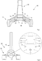
Figure 1 : une vue en coupe longitudinale d'une fourche de vélo selon l'invention selon un premier plan sensiblement vertical, -
Figure 2 : une vue en coupe longitudinale d'une fourche de vélo selon lafigure 1 selon un second plan sensiblement vertical et une vue de détail de ladite vue en coupe, -
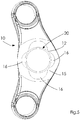
Figure 3 : une vue en perspective d'une tête de fourche selon l'invention, -
Figure 4 : une vue de détail d'une coupe transversale d'un logement d'une tête de fourche, -
Figure 5 : une vue en coupe longitudinale selon un plan horizontal d'une fourche de vélo selon lafigure 1 . - Dans ces figures, des références numériques identiques d'une figure à l'autre désignent des éléments identiques ou analogues. Par ailleurs, pour des raisons de clarté, les dessins ne sont pas à l'échelle.
- La présente invention concerne une tête de fourche 10 comprenant un logement 11 traversant destiné à recevoir fixement un pivot de fourche 20 afin de former une fourche de vélo 30.
- Le logement 11 est, par exemple, formé par un alésage s'étendant selon un axe longitudinal A sur la
figure 1 , et comporte une paroi intérieure comprenant un chambrage définissant une gorge 12 radiale. La paroi intérieure comprend également deux portées annulaires intérieures 13 et 14 d'appui dudit pivot de fourche 20. Comme le montrent lesfigures 1 à 4 , la gorge radiale est interposée entre les deux portées annulaires intérieures 13 et 14 d'appui dudit pivot de fourche 20. - Par le terme « radial », on entend ici que la gorge s'étend suivant le rayon d'un cercle et suivant la totalité de la périphérie de ce cercle.
- Comme le représentent les
figures 2 ,3 et 4 dans un exemple préféré de réalisation, la gorge 12 et les portées annulaires intérieures 13 et 14 présentent la forme d'éléments géométriques de révolution, de même que le logement 11, et partagent le même axe de révolution que ce dernier. - Les portées annulaires intérieures 13 et 14 présentent respectivement la forme d'une bague dont la paroi interne est destinée à maintenir en position le pivot de fourche 20 par serrage. Plus précisément, le pivot de fourche 20 présente la forme d'un tube creux dont les parois sont d'épaisseur constante et comprend, à l'une de ses extrémités dite « extrémité inférieure », deux portées annulaires extérieures 21 et 22 respectivement destinées à être emmanchées dans les portées annulaires intérieures 13 et 14.
- En plus de l'action de serrage, il peut être prévu d'ajouter de la colle ou tout autre matériau adhésif à l'interface entre le logement 11 de la tête de fourche 10 et le pivot de fourche 20. Dans ce cas, la gorge 12 peut avantageusement constituer un réservoir de colle ou de tout autre matériau adhésif.
- Comme représenté sur les
figures 1 à 4 , le logement 11 s'étend entre une première extrémité dite « extrémité supérieure » et une seconde extrémité dite « extrémité inférieure ». Le logement 11 comprend une portée annulaire intérieure 13 et 14 à chacune de ses extrémités supérieure et inférieure, appelées respectivement dans la présente description « portée annulaire intérieure supérieure » 13 et « portée annulaire intérieure inférieure » 14. - Avantageusement, les portées annulaires intérieures supérieure 13 et inférieure 14 présentent préférentiellement un diamètre différent l'une de l'autre. Plus particulièrement, dans l'exemple de réalisation représenté par les
figures 1 à 5 , le diamètre de la portée annulaire intérieure inférieure 14 est sensiblement plus important que celui de la portée annulaire intérieure supérieure 13. - De manière analogue, la portée extérieure 22 la plus proche de l'extrémité inférieure du pivot de fourche 20 présente un diamètre sensiblement plus important que l'autre portée extérieure 21.
- Ceci a notamment pour effet de faciliter l'emmanchement du pivot de fourche 20 dans le logement 11 de la tête de fourche 10, et d'éliminer les risques d'endommagement du pivot de fourche 20 et de la tête de fourche 10 lors de l'emmanchement. En effet, dans cette configuration, les efforts de serrage sont appliqués par les deux portées annulaires intérieures supérieure 13 et inférieure 14 sur les portées annulaires extérieures 21 et 22 du pivot de fourche 20 de façon concomitante. Il y a lieu de noter que l'emmanchement du pivot de fourche 20 dans le logement 11 de la tête de fourche 10 peut être réalisé par l'utilisation de tout outil approprié, tel qu'une presse hydraulique connue de l'homme du métier.
- Les deux portées annulaires extérieures 21 et 22 sont avantageusement reliées l'une à l'autre par une portion tronconique 23. Les concentrations de contraintes sont ainsi limitées dans le pivot de fourche 20, notamment lors de l'emmanchement.
- En outre, le pivot de fourche 20 comprend, à son extrémité inférieure, une collerette 24 s'étendant vers l'extérieure. Cette collerette 24 est prévue pour être logée dans un lamage dont est pourvue la tête de fourche 10 à son extrémité inférieure, tel qu'illustré par les
figures 1 et 2 . La collerette 24 est destinée à venir en butée contre le lamage lors de l'emmanchement du pivot de fourche 20 dans le logement 11. - Dans l'exemple de réalisation représenté par les
figures 1 à 5 , les portées annulaires intérieures supérieure 13 et inférieure 14 sont concentriques, de même que les portées annulaires extérieures 21 et 22. - Par ailleurs, la gorge 12 peut avantageusement comprendre des nervures 15 afin de renforcer la résistance aux contraintes mécanique des portées annulaires intérieures supérieure 13 et inférieure 14 et d'éviter toute déformation ou détérioration desdites portées 13 et 14 lors de l'emmanchement du pivot de fourche 20. Les nervures 15 peuvent s'étendre axialement, tel que représenté sur les
figures 3 à 5 , de la portée annulaire inférieure 14 jusqu'à la portée annulaire supérieure 13. - Comme le montrent les
figures 1 et3 à 5 , la gorge peut comprendre des cavités 16 internes radiales interposée entre deux nervures adjacentes. Ces cavités 16 sont également interposées entre les deux portées annulaires intérieures 13 et 14, de la même manière que la gorge 12. Ces cavités 16 sont borgnes, dans le sens où elles présentent une unique ouverture débouchant en vis-à-vis du logement 11. En outre, elles présentent préférentiellement la forme de lobes concaves, comme le montrent lesfigures 3 à 5 , et sont préférentiellement au nombre de quatre. - Ces cavités 16 internes permettent avantageusement de réduire davantage le poids de la tête de fourche sans compromettre sa résistance aux contraintes mécaniques.
- De manière plus générale, il est à noter que les modes de mise en oeuvre et de réalisation considérés ci-dessus ont été décrits à titre d'exemples non limitatifs, et que d'autres variantes sont par conséquent envisageables.
Claims (8)
- Tête de fourche (10) de vélo comprenant un logement (11) traversant destiné à recevoir fixement un pivot de fourche (20) de vélo, ladite tête de fourche (10) étant caractérisée en ce que ledit logement (11) comporte un chambrage définissant une gorge (12) interposée entre deux portées annulaires intérieures (13, 14) d'appui dudit pivot.
- Tête de fourche (10) de vélo selon la revendication 1, dans laquelle les portées annulaires intérieures (13, 14) présentent un diamètre différent l'une de l'autre.
- Tête de fourche (10) de vélo selon l'une des revendications 1 ou 2, dans laquelle la gorge (12) comprend des nervures (15).
- Tête de fourche (10) de vélo selon l'une des revendications 1 à 3, dans laquelle le logement (11) s'étend entre une première extrémité dite « extrémité supérieure » et une seconde extrémité dite « extrémité inférieure », ledit logement (11) comprenant une portée annulaire intérieure (13, 14) à chacune de ses extrémités supérieure et inférieure.
- Pivot de fourche (20) de vélo destiné à être emmanché fixement dans un logement (11) d'une tête de fourche (10) selon l'une des revendications 1 à 4, s'étendant entre deux extrémités longitudinales et présentant au moins deux portées annulaires extérieures (21, 22) respectivement arrangées de sorte à être en appui contre des portées annulaires intérieures (13, 14) lorsque le pivot de fourche (20) de vélo est emmanché fixement dans le logement (11) de ladite tête de fourche (10).
- Pivot de fourche (20) de vélo selon la revendication 5, dans lequel les au moins deux portées annulaires extérieures (21, 22) présentent un diamètre différent l'une de l'autre, et dans lequel elles sont reliées entre elles par au moins une portion tronconique (23).
- Pivot de fourche (20) de vélo selon l'une des revendications 5 ou 6 formé par un tube creux dont la paroi est d'épaisseur constante.
- Fourche de vélo comprenant un pivot de fourche (20) de vélo selon l'une des revendications 5 à 7 rigidement fixé à une tête de fourche (10) selon l'une des revendications 1 à 4.
Applications Claiming Priority (1)
| Application Number | Priority Date | Filing Date | Title |
|---|---|---|---|
| FR1752891A FR3064591B1 (fr) | 2017-04-04 | 2017-04-04 | Fourche de velo et pivot et tete de fourche la composant |
Publications (2)
| Publication Number | Publication Date |
|---|---|
| EP3385152A1 true EP3385152A1 (fr) | 2018-10-10 |
| EP3385152B1 EP3385152B1 (fr) | 2020-07-01 |
Family
ID=59153079
Family Applications (1)
| Application Number | Title | Priority Date | Filing Date |
|---|---|---|---|
| EP18165720.6A Active EP3385152B1 (fr) | 2017-04-04 | 2018-04-04 | Fourche de vélo et pivot et tête de fourche la composant |
Country Status (3)
| Country | Link |
|---|---|
| EP (1) | EP3385152B1 (fr) |
| ES (1) | ES2825048T3 (fr) |
| FR (1) | FR3064591B1 (fr) |
Citations (3)
| Publication number | Priority date | Publication date | Assignee | Title |
|---|---|---|---|---|
| US5762352A (en) * | 1996-03-15 | 1998-06-09 | Lee; Kyu-Wang | Bicycle fork having a fiber reinforced steerer tube and fiber reinforced crown and blades and method of making same |
| US20060186632A1 (en) * | 2005-02-22 | 2006-08-24 | Hui-Hsiung Chen | Structure of crown portion for bicycles |
| DE102013214584A1 (de) * | 2013-07-25 | 2015-01-29 | Bayerische Motoren Werke Aktiengesellschaft | Gabelbrücke für die Vorderradaufhängung eines motorisierten Zweirads und Verfahren zu deren Herstellung |
-
2017
- 2017-04-04 FR FR1752891A patent/FR3064591B1/fr active Active
-
2018
- 2018-04-04 EP EP18165720.6A patent/EP3385152B1/fr active Active
- 2018-04-04 ES ES18165720T patent/ES2825048T3/es active Active
Patent Citations (3)
| Publication number | Priority date | Publication date | Assignee | Title |
|---|---|---|---|---|
| US5762352A (en) * | 1996-03-15 | 1998-06-09 | Lee; Kyu-Wang | Bicycle fork having a fiber reinforced steerer tube and fiber reinforced crown and blades and method of making same |
| US20060186632A1 (en) * | 2005-02-22 | 2006-08-24 | Hui-Hsiung Chen | Structure of crown portion for bicycles |
| DE102013214584A1 (de) * | 2013-07-25 | 2015-01-29 | Bayerische Motoren Werke Aktiengesellschaft | Gabelbrücke für die Vorderradaufhängung eines motorisierten Zweirads und Verfahren zu deren Herstellung |
Also Published As
| Publication number | Publication date |
|---|---|
| ES2825048T3 (es) | 2021-05-14 |
| FR3064591B1 (fr) | 2020-10-16 |
| EP3385152B1 (fr) | 2020-07-01 |
| FR3064591A1 (fr) | 2018-10-05 |
Similar Documents
| Publication | Publication Date | Title |
|---|---|---|
| EP2177373B1 (fr) | Dispositif de montage de roulements et moyeu de roue de bicyclette incluant ledit dispositif | |
| EP1916182A1 (fr) | Jeu de direction de cycle | |
| EP2904889B1 (fr) | Roue formant outil agricole amélioré | |
| EP1780113B1 (fr) | Pedale automatique de cycle à arceaux d'accrochage | |
| FR2917332A1 (fr) | Roue comprenant une jante, un moyeu, et un dispositif de raccordement de la jante au moyeu | |
| EP2937273B1 (fr) | Ensemble pour cycle | |
| EP3572238B1 (fr) | Moyeu pour roue de cycle | |
| FR3052433A1 (fr) | Systeme de suspension arriere pour velo | |
| FR3039458A1 (fr) | Moyeu pour roue de cycle | |
| EP4015263B1 (fr) | Vehicule automobile | |
| FR3003201A1 (fr) | Assemblage d’un moyeu de roue motrice et d’un bol de joint de transmission | |
| EP2265445B1 (fr) | Rayon pour une roue a rayons, roue et procede correspondants | |
| EP3385152B1 (fr) | Fourche de vélo et pivot et tête de fourche la composant | |
| EP4103855B1 (fr) | Bielle ajustable en longueur munie d'un dispositif de couple résistant | |
| EP2933179B1 (fr) | Cadre de cycle et tige de selle associée | |
| EP2435686A1 (fr) | Piece de fixation entre la partie mobile d'un divergent deployable de propulseur et un mecanisme de deploiement de cette partie mobile. | |
| FR3115849A1 (fr) | Differentiel de boîte de vitesse a joncs d’arret d’axe porte-satellite | |
| EP3329138B1 (fr) | Soufflet de protection pour joint de transmission et ensemble de transmission correspondant | |
| FR2815928A1 (fr) | Assemblage d'une potence de bicyclette avec un pivot de fourche et un jeu de direction, potence et dispositif de reglage pour un tel assemblage | |
| EP1798058A2 (fr) | Moyeu de roue et roue munie du moyeu | |
| FR2876612A1 (fr) | Cle a limitation de couple amelioree | |
| FR3166674A1 (fr) | Dispositif de freinage à tenons de transmission de couple rapportés, roue, atterrisseur et aéronef le comportant. | |
| FR2825320A1 (fr) | Moyeu de roue et roue ayant un tel moyeu | |
| WO2017191398A2 (fr) | Dispositif de fixation de rayons sur une roue de bicyclette | |
| WO2008087265A2 (fr) | Roue arriere de cycle |
Legal Events
| Date | Code | Title | Description |
|---|---|---|---|
| PUAI | Public reference made under article 153(3) epc to a published international application that has entered the european phase |
Free format text: ORIGINAL CODE: 0009012 |
|
| STAA | Information on the status of an ep patent application or granted ep patent |
Free format text: STATUS: THE APPLICATION HAS BEEN PUBLISHED |
|
| AK | Designated contracting states |
Kind code of ref document: A1 Designated state(s): AL AT BE BG CH CY CZ DE DK EE ES FI FR GB GR HR HU IE IS IT LI LT LU LV MC MK MT NL NO PL PT RO RS SE SI SK SM TR |
|
| AX | Request for extension of the european patent |
Extension state: BA ME |
|
| STAA | Information on the status of an ep patent application or granted ep patent |
Free format text: STATUS: REQUEST FOR EXAMINATION WAS MADE |
|
| 17P | Request for examination filed |
Effective date: 20190403 |
|
| RBV | Designated contracting states (corrected) |
Designated state(s): AL AT BE BG CH CY CZ DE DK EE ES FI FR GB GR HR HU IE IS IT LI LT LU LV MC MK MT NL NO PL PT RO RS SE SI SK SM TR |
|
| GRAP | Despatch of communication of intention to grant a patent |
Free format text: ORIGINAL CODE: EPIDOSNIGR1 |
|
| STAA | Information on the status of an ep patent application or granted ep patent |
Free format text: STATUS: GRANT OF PATENT IS INTENDED |
|
| INTG | Intention to grant announced |
Effective date: 20200115 |
|
| GRAS | Grant fee paid |
Free format text: ORIGINAL CODE: EPIDOSNIGR3 |
|
| GRAA | (expected) grant |
Free format text: ORIGINAL CODE: 0009210 |
|
| STAA | Information on the status of an ep patent application or granted ep patent |
Free format text: STATUS: THE PATENT HAS BEEN GRANTED |
|
| AK | Designated contracting states |
Kind code of ref document: B1 Designated state(s): AL AT BE BG CH CY CZ DE DK EE ES FI FR GB GR HR HU IE IS IT LI LT LU LV MC MK MT NL NO PL PT RO RS SE SI SK SM TR |
|
| REG | Reference to a national code |
Ref country code: CH Ref legal event code: EP Ref country code: AT Ref legal event code: REF Ref document number: 1285927 Country of ref document: AT Kind code of ref document: T Effective date: 20200715 |
|
| REG | Reference to a national code |
Ref country code: IE Ref legal event code: FG4D Free format text: LANGUAGE OF EP DOCUMENT: FRENCH |
|
| REG | Reference to a national code |
Ref country code: DE Ref legal event code: R096 Ref document number: 602018005624 Country of ref document: DE |
|
| REG | Reference to a national code |
Ref country code: SE Ref legal event code: TRGR |
|
| REG | Reference to a national code |
Ref country code: NL Ref legal event code: FP |
|
| REG | Reference to a national code |
Ref country code: LT Ref legal event code: MG4D |
|
| PG25 | Lapsed in a contracting state [announced via postgrant information from national office to epo] |
Ref country code: BG Free format text: LAPSE BECAUSE OF FAILURE TO SUBMIT A TRANSLATION OF THE DESCRIPTION OR TO PAY THE FEE WITHIN THE PRESCRIBED TIME-LIMIT Effective date: 20201001 |
|
| PG25 | Lapsed in a contracting state [announced via postgrant information from national office to epo] |
Ref country code: PT Free format text: LAPSE BECAUSE OF FAILURE TO SUBMIT A TRANSLATION OF THE DESCRIPTION OR TO PAY THE FEE WITHIN THE PRESCRIBED TIME-LIMIT Effective date: 20201102 Ref country code: HR Free format text: LAPSE BECAUSE OF FAILURE TO SUBMIT A TRANSLATION OF THE DESCRIPTION OR TO PAY THE FEE WITHIN THE PRESCRIBED TIME-LIMIT Effective date: 20200701 Ref country code: NO Free format text: LAPSE BECAUSE OF FAILURE TO SUBMIT A TRANSLATION OF THE DESCRIPTION OR TO PAY THE FEE WITHIN THE PRESCRIBED TIME-LIMIT Effective date: 20201001 Ref country code: LT Free format text: LAPSE BECAUSE OF FAILURE TO SUBMIT A TRANSLATION OF THE DESCRIPTION OR TO PAY THE FEE WITHIN THE PRESCRIBED TIME-LIMIT Effective date: 20200701 Ref country code: GR Free format text: LAPSE BECAUSE OF FAILURE TO SUBMIT A TRANSLATION OF THE DESCRIPTION OR TO PAY THE FEE WITHIN THE PRESCRIBED TIME-LIMIT Effective date: 20201002 Ref country code: FI Free format text: LAPSE BECAUSE OF FAILURE TO SUBMIT A TRANSLATION OF THE DESCRIPTION OR TO PAY THE FEE WITHIN THE PRESCRIBED TIME-LIMIT Effective date: 20200701 Ref country code: CZ Free format text: LAPSE BECAUSE OF FAILURE TO SUBMIT A TRANSLATION OF THE DESCRIPTION OR TO PAY THE FEE WITHIN THE PRESCRIBED TIME-LIMIT Effective date: 20200701 |
|
| PG25 | Lapsed in a contracting state [announced via postgrant information from national office to epo] |
Ref country code: LV Free format text: LAPSE BECAUSE OF FAILURE TO SUBMIT A TRANSLATION OF THE DESCRIPTION OR TO PAY THE FEE WITHIN THE PRESCRIBED TIME-LIMIT Effective date: 20200701 Ref country code: PL Free format text: LAPSE BECAUSE OF FAILURE TO SUBMIT A TRANSLATION OF THE DESCRIPTION OR TO PAY THE FEE WITHIN THE PRESCRIBED TIME-LIMIT Effective date: 20200701 Ref country code: RS Free format text: LAPSE BECAUSE OF FAILURE TO SUBMIT A TRANSLATION OF THE DESCRIPTION OR TO PAY THE FEE WITHIN THE PRESCRIBED TIME-LIMIT Effective date: 20200701 Ref country code: IS Free format text: LAPSE BECAUSE OF FAILURE TO SUBMIT A TRANSLATION OF THE DESCRIPTION OR TO PAY THE FEE WITHIN THE PRESCRIBED TIME-LIMIT Effective date: 20201101 |
|
| REG | Reference to a national code |
Ref country code: DE Ref legal event code: R097 Ref document number: 602018005624 Country of ref document: DE |
|
| PG25 | Lapsed in a contracting state [announced via postgrant information from national office to epo] |
Ref country code: SM Free format text: LAPSE BECAUSE OF FAILURE TO SUBMIT A TRANSLATION OF THE DESCRIPTION OR TO PAY THE FEE WITHIN THE PRESCRIBED TIME-LIMIT Effective date: 20200701 Ref country code: EE Free format text: LAPSE BECAUSE OF FAILURE TO SUBMIT A TRANSLATION OF THE DESCRIPTION OR TO PAY THE FEE WITHIN THE PRESCRIBED TIME-LIMIT Effective date: 20200701 Ref country code: RO Free format text: LAPSE BECAUSE OF FAILURE TO SUBMIT A TRANSLATION OF THE DESCRIPTION OR TO PAY THE FEE WITHIN THE PRESCRIBED TIME-LIMIT Effective date: 20200701 Ref country code: DK Free format text: LAPSE BECAUSE OF FAILURE TO SUBMIT A TRANSLATION OF THE DESCRIPTION OR TO PAY THE FEE WITHIN THE PRESCRIBED TIME-LIMIT Effective date: 20200701 |
|
| PLBE | No opposition filed within time limit |
Free format text: ORIGINAL CODE: 0009261 |
|
| STAA | Information on the status of an ep patent application or granted ep patent |
Free format text: STATUS: NO OPPOSITION FILED WITHIN TIME LIMIT |
|
| REG | Reference to a national code |
Ref country code: ES Ref legal event code: FG2A Ref document number: 2825048 Country of ref document: ES Kind code of ref document: T3 Effective date: 20210514 |
|
| PG25 | Lapsed in a contracting state [announced via postgrant information from national office to epo] |
Ref country code: AL Free format text: LAPSE BECAUSE OF FAILURE TO SUBMIT A TRANSLATION OF THE DESCRIPTION OR TO PAY THE FEE WITHIN THE PRESCRIBED TIME-LIMIT Effective date: 20200701 |
|
| 26N | No opposition filed |
Effective date: 20210406 |
|
| REG | Reference to a national code |
Ref country code: AT Ref legal event code: UEP Ref document number: 1285927 Country of ref document: AT Kind code of ref document: T Effective date: 20200701 |
|
| PG25 | Lapsed in a contracting state [announced via postgrant information from national office to epo] |
Ref country code: SK Free format text: LAPSE BECAUSE OF FAILURE TO SUBMIT A TRANSLATION OF THE DESCRIPTION OR TO PAY THE FEE WITHIN THE PRESCRIBED TIME-LIMIT Effective date: 20200701 |
|
| PG25 | Lapsed in a contracting state [announced via postgrant information from national office to epo] |
Ref country code: SI Free format text: LAPSE BECAUSE OF FAILURE TO SUBMIT A TRANSLATION OF THE DESCRIPTION OR TO PAY THE FEE WITHIN THE PRESCRIBED TIME-LIMIT Effective date: 20200701 |
|
| PG25 | Lapsed in a contracting state [announced via postgrant information from national office to epo] |
Ref country code: MC Free format text: LAPSE BECAUSE OF FAILURE TO SUBMIT A TRANSLATION OF THE DESCRIPTION OR TO PAY THE FEE WITHIN THE PRESCRIBED TIME-LIMIT Effective date: 20200701 |
|
| PG25 | Lapsed in a contracting state [announced via postgrant information from national office to epo] |
Ref country code: LU Free format text: LAPSE BECAUSE OF NON-PAYMENT OF DUE FEES Effective date: 20210404 |
|
| PG25 | Lapsed in a contracting state [announced via postgrant information from national office to epo] |
Ref country code: IE Free format text: LAPSE BECAUSE OF NON-PAYMENT OF DUE FEES Effective date: 20210404 |
|
| PG25 | Lapsed in a contracting state [announced via postgrant information from national office to epo] |
Ref country code: IS Free format text: LAPSE BECAUSE OF FAILURE TO SUBMIT A TRANSLATION OF THE DESCRIPTION OR TO PAY THE FEE WITHIN THE PRESCRIBED TIME-LIMIT Effective date: 20201101 |
|
| PG25 | Lapsed in a contracting state [announced via postgrant information from national office to epo] |
Ref country code: CY Free format text: LAPSE BECAUSE OF FAILURE TO SUBMIT A TRANSLATION OF THE DESCRIPTION OR TO PAY THE FEE WITHIN THE PRESCRIBED TIME-LIMIT Effective date: 20200701 |
|
| PG25 | Lapsed in a contracting state [announced via postgrant information from national office to epo] |
Ref country code: HU Free format text: LAPSE BECAUSE OF FAILURE TO SUBMIT A TRANSLATION OF THE DESCRIPTION OR TO PAY THE FEE WITHIN THE PRESCRIBED TIME-LIMIT; INVALID AB INITIO Effective date: 20180404 |
|
| PG25 | Lapsed in a contracting state [announced via postgrant information from national office to epo] |
Ref country code: MK Free format text: LAPSE BECAUSE OF FAILURE TO SUBMIT A TRANSLATION OF THE DESCRIPTION OR TO PAY THE FEE WITHIN THE PRESCRIBED TIME-LIMIT Effective date: 20200701 |
|
| PG25 | Lapsed in a contracting state [announced via postgrant information from national office to epo] |
Ref country code: MT Free format text: LAPSE BECAUSE OF FAILURE TO SUBMIT A TRANSLATION OF THE DESCRIPTION OR TO PAY THE FEE WITHIN THE PRESCRIBED TIME-LIMIT Effective date: 20200701 |
|
| PGFP | Annual fee paid to national office [announced via postgrant information from national office to epo] |
Ref country code: SE Payment date: 20250314 Year of fee payment: 8 |
|
| PGFP | Annual fee paid to national office [announced via postgrant information from national office to epo] |
Ref country code: NL Payment date: 20250429 Year of fee payment: 8 |
|
| PGFP | Annual fee paid to national office [announced via postgrant information from national office to epo] |
Ref country code: DE Payment date: 20250429 Year of fee payment: 8 |
|
| PGFP | Annual fee paid to national office [announced via postgrant information from national office to epo] |
Ref country code: GB Payment date: 20250430 Year of fee payment: 8 Ref country code: ES Payment date: 20250507 Year of fee payment: 8 |
|
| PGFP | Annual fee paid to national office [announced via postgrant information from national office to epo] |
Ref country code: IT Payment date: 20250429 Year of fee payment: 8 Ref country code: BE Payment date: 20250428 Year of fee payment: 8 |
|
| PGFP | Annual fee paid to national office [announced via postgrant information from national office to epo] |
Ref country code: FR Payment date: 20250430 Year of fee payment: 8 |
|
| PGFP | Annual fee paid to national office [announced via postgrant information from national office to epo] |
Ref country code: CH Payment date: 20250602 Year of fee payment: 8 |
|
| PGFP | Annual fee paid to national office [announced via postgrant information from national office to epo] |
Ref country code: AT Payment date: 20250429 Year of fee payment: 8 |
|
| PG25 | Lapsed in a contracting state [announced via postgrant information from national office to epo] |
Ref country code: TR Free format text: LAPSE BECAUSE OF FAILURE TO SUBMIT A TRANSLATION OF THE DESCRIPTION OR TO PAY THE FEE WITHIN THE PRESCRIBED TIME-LIMIT Effective date: 20200701 |