EP3385199B1 - Procédé et butée de palettes destinés à arrêter une marchandise monobloc - Google Patents
Procédé et butée de palettes destinés à arrêter une marchandise monobloc Download PDFInfo
- Publication number
- EP3385199B1 EP3385199B1 EP17165285.2A EP17165285A EP3385199B1 EP 3385199 B1 EP3385199 B1 EP 3385199B1 EP 17165285 A EP17165285 A EP 17165285A EP 3385199 B1 EP3385199 B1 EP 3385199B1
- Authority
- EP
- European Patent Office
- Prior art keywords
- stop
- reset
- feed path
- feed
- pallet stopper
- Prior art date
- Legal status (The legal status is an assumption and is not a legal conclusion. Google has not performed a legal analysis and makes no representation as to the accuracy of the status listed.)
- Active
Links
Images


Classifications
-
- B—PERFORMING OPERATIONS; TRANSPORTING
- B65—CONVEYING; PACKING; STORING; HANDLING THIN OR FILAMENTARY MATERIAL
- B65G—TRANSPORT OR STORAGE DEVICES, e.g. CONVEYORS FOR LOADING OR TIPPING, SHOP CONVEYOR SYSTEMS OR PNEUMATIC TUBE CONVEYORS
- B65G47/00—Article or material-handling devices associated with conveyors; Methods employing such devices
- B65G47/74—Feeding, transfer, or discharging devices of particular kinds or types
- B65G47/88—Separating or stopping elements, e.g. fingers
- B65G47/8807—Separating or stopping elements, e.g. fingers with one stop
- B65G47/8815—Reciprocating stop, moving up or down in the path of the article
-
- B—PERFORMING OPERATIONS; TRANSPORTING
- B65—CONVEYING; PACKING; STORING; HANDLING THIN OR FILAMENTARY MATERIAL
- B65G—TRANSPORT OR STORAGE DEVICES, e.g. CONVEYORS FOR LOADING OR TIPPING, SHOP CONVEYOR SYSTEMS OR PNEUMATIC TUBE CONVEYORS
- B65G47/00—Article or material-handling devices associated with conveyors; Methods employing such devices
- B65G47/74—Feeding, transfer, or discharging devices of particular kinds or types
- B65G47/88—Separating or stopping elements, e.g. fingers
- B65G47/8807—Separating or stopping elements, e.g. fingers with one stop
- B65G47/8823—Pivoting stop, swinging in or out of the path of the article
-
- B—PERFORMING OPERATIONS; TRANSPORTING
- B65—CONVEYING; PACKING; STORING; HANDLING THIN OR FILAMENTARY MATERIAL
- B65G—TRANSPORT OR STORAGE DEVICES, e.g. CONVEYORS FOR LOADING OR TIPPING, SHOP CONVEYOR SYSTEMS OR PNEUMATIC TUBE CONVEYORS
- B65G2205/00—Stopping elements used in conveyors to stop articles or arrays of articles
- B65G2205/04—Stopping elements used in conveyors to stop articles or arrays of articles where the stop device is not adaptable
-
- B—PERFORMING OPERATIONS; TRANSPORTING
- B65—CONVEYING; PACKING; STORING; HANDLING THIN OR FILAMENTARY MATERIAL
- B65G—TRANSPORT OR STORAGE DEVICES, e.g. CONVEYORS FOR LOADING OR TIPPING, SHOP CONVEYOR SYSTEMS OR PNEUMATIC TUBE CONVEYORS
- B65G2205/00—Stopping elements used in conveyors to stop articles or arrays of articles
- B65G2205/06—Cushioned or damping stop devices, e.g. using springs or other mechanical actions
Definitions
- the invention relates firstly to a method for stopping a lumpy product which is conveyed by means of a continuous conveying device along a conveying path in a conveying direction to a stopping point, wherein at the stopping point a stop is first moved from a reset position outside the conveying path into the conveying path in such a way that the product runs onto the stop and displaces it in the conveying direction by a damping length, wherein an impulse of the product is dissipated by a throttle element when a fluid flows through it, and wherein the stop is then removed from the conveying path and moved back into the reset position by the damping length against the conveying direction.
- the invention further relates to a pallet stopper for carrying out such a method.
- Such a procedure and a corresponding pallet stopper are EN 10 2007 024 300 A1 known, whereby the stop is moved by means of a transverse drive transversely to the conveying direction from the return position into the conveying path and back.
- the housing of the known pallet stopper encloses the stop in both positions and has a corresponding height.
- DE 195 43 797 A1 discloses a method according to the preamble of claim 1 and a pallet stopper according to the preamble of claim 5.
- the invention is based on the object of reducing the height of the pallet stopper.
- the stated object is achieved by a method for stopping a piece of goods according to claim 1 and by a pallet stopper according to claim 5.
- the invention proposes that the stop is pivoted from the return position into the conveyor line and from the conveyor line into the return position around the conveying direction.
- the pallet stop according to the invention has a height reduced by the difference between the heights of the return position and the position in the conveyor line.
- the stop is pivoted in one direction of rotation from the return position into the conveying path and in the opposite direction of rotation from the conveying path into the return position around the conveying direction.
- the housing therefore does not have to provide any additional space for the movement in the opposite direction of rotation.
- the stop is pivoted into the conveyor section by a defined pivot angle of the return.
- the housing therefore does not have to provide any additional space for movements with a larger pivot angle.
- the stop is moved back by the damping length after the goods have been removed from the conveyor line when the stop point is passed.
- the pallet stopper therefore does not require any additional drive for resetting.
- the stop or the housing can have a spiral around the longitudinal axis of the stop, so that the reset drive simultaneously causes a rotational movement of the stop. In this case, there is no need for reset via the goods.
- the invention proposes that the stop can be pivoted about the conveying direction by means of the drive.
- the pallet stopper according to the invention enables the above method to be carried out and is equally characterized by the advantages listed there.
- the drive in a pallet stopper according to the invention is a motor. Electric motors are available in many variants on the market at low cost. Alternatively, the stop can also be pivoted by an electromagnet or a pneumatic or hydraulic drive.
- the damping element has a piston which is in a piston filled with the fluid is movable.
- a piston which is in a piston filled with the fluid is movable.
- an electro-rheological damping element or an elastomer can be used.
- the piston is mechanically connected to the stop in such a way that when the stop is displaced in the conveying direction, it is moved against the conveying direction.
- the damping element can be arranged next to the stop (in particular under it).
- the stop is made of steel.
- the reset drive has a reset stop that the goods actuate when they pass over the stop point.
- such a reset stop is made of steel and such a pallet stopper has an elastomer element that limits movement of the reset stop against the conveying direction. If the pallet stopper is hit by the goods against the conveying direction due to incorrect operation, the goods can pass over the reset stop without causing any damage.
- the stop or the reset stop can be hinged against the conveying direction and, for example, be spring-loaded in order to achieve the same goal in each case.
- the stop is secured against destruction.
- the reset can be carried out via a guide rail, via an incline, linearly or via a longitudinal groove. In such pallet stoppers according to the invention, no reset stop is required.
- a pallet stopper according to the invention has at least one inductive or capacitive sensor to detect the position of the stop in the Conveying direction and/or the swivel position of the stop to determine the position of the stop
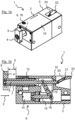
- the first pallet stopper 1 has a cuboid housing 3 with an approximately square cross-section that is elongated in the conveying direction 2, as well as a cuboid stop 4 made of steel that can be displaced by a damping length 5 against a throttle element 6 of the pallet stopper 1.
- the stop 4 is clamped onto a tubular stop carrier 7, which is pivotable about the conveying direction 2 on a cylindrical stop axis 8 and is mounted with the stop axis 8 in the housing 3 so as to be displaceable about the damping length 5 in the conveying direction 2.
- the stop head 9 of the stop 4 points vertically upwards beyond an upper side 10 of the housing 3.
- the pallet stopper 1 has a motor (not shown) as a drive 11 for pivoting the stop 4, which is integrated into a gear segment 12 on the The stop carrier 7 and thus the stop 4 can be rotated by means of the drive 11 through a pivoting angle 13 of 90 ° from the end position into the Figures 3b and 4 shown intermediate position and back from the Figures 3b and 5 shown reset to the start position.
- a motor not shown
- the stop 4 can be rotated by means of the drive 11 through a pivoting angle 13 of 90 ° from the end position into the Figures 3b and 4 shown intermediate position and back from the Figures 3b and 5 shown reset to the start position.
- the throttle element 6 has an air-filled damping cylinder 14 arranged parallel to the conveying direction 2 under the axis in the housing 3, a piston 15 slidably mounted in the damping cylinder 14 and a check valve 17 adjustable via an adjusting screw 16 in the top 10 of the housing 3.
- the piston 15 is connected to a lever 18 which is mounted in a lever axis 19 running transversely to the conveying direction 2 in the housing 3.
- the lever 18 connects the piston 15 to the stop axis 8 in such a way that both move in opposite directions.
- the piston 15 When the stop carrier 7 is moved into the housing 3, the piston 15 is moved into the damping cylinder 14 and compresses the air contained therein, which escapes from the housing 3 against the check valve 17 and dissipates the momentum of the material hitting the stop 4 into heat.
- the check valve 17 opens and the damping cylinder 14 fills with air again.
- the first pallet stopper 1 has a steel reset stop 20 coupled to the stop axis 8.
- the reset stop 20 is mounted in the housing 3 about a reset axis 21 parallel to the lever axis 19.
- a reset head 22 of the reset stop 20 lies in the starting position in the housing 3 and is aligned against the conveying direction 2 over the top 10 of the housing 3 when the stop carrier 7 is moved into the housing 3.
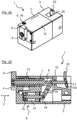
- the second pallet stopper 23 corresponds largely to the first pallet stopper 1.
- the reset stop 24 of the second pallet stopper 23 has a roller 26 arranged opposite the reset head 25, onto which the stop axis 27 runs.
- the pallet stopper 23 also has a Elastomer element 28 onto which the reset head 25 runs and which thus limits a movement of the reset stop 24 against the conveying direction 29.
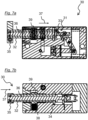
- the third pallet stopper 30 according to the invention, shown in two sections, largely corresponds to the first pallet stopper 1. Instead of a reset stop, the third pallet stopper 30 has a link guide 31 with a guide groove 33 surrounding the stop carrier 32 in a thread-shaped manner and a guide bolt 34 attached to the stop carrier 32, which is guided in the guide groove 33.
- the pallet stoppers 1, 23, 30 according to the invention are equally suitable for stopping a piece of goods, for example a pallet, which is conveyed along a conveyor line by means of a continuous conveyor device, for example a conveyor belt.
- a continuous conveyor device for example a conveyor belt.
- the piece of goods, the continuous conveyor device and the conveyor line are not shown.
- the pallet stoppers 1, 23, 30 are installed in the conveyor system in such a way that the upper side 10 of the housing 3 is flush with the conveyor line and in the Figures 1 a/b, 3a and 6 shown starting position only the stop 4 and in the position shown in the Figures 2a /b shown end position of the reset stop 20, 24 protrude into the conveyor line.
- the material runs against the stop 4 and moves it in the conveying direction 2, 29 from the starting position to the Figures 2a /b shown end position.
- the lever 18 transfers the movement of the stop 4 to the piston 15, which is moved accordingly in the cylinder.
- the momentum of the material as the hydraulic oil flows through the piston 15 is converted into heat and dissipated.
- the movement of the stop 4 is also transferred to the reset stop 20, 24, which is raised into the conveyor line.
- the stop 4 is moved by the motor through the swivel angle 13 from the conveyor line into the Figures 3b and 4 shown intermediate position into the housing 3.
- the movement of the stop 35 in the stop axis 36 is thus always directly coupled with a pivoting movement of the stop 35 about the stop axis 36:
- the link guide 31 By means of the link guide 31, the displacement of the stop 35 from the starting position by the accumulating goods in the conveying direction 37 is simultaneously converted into a pivoting movement about the stop axis 36 into the intermediate position, and the pivoting movement transmitted by the drive 38 for resetting to the gear 39 and the stop carrier 32 is simultaneously converted into a restoring longitudinal movement against the conveying direction 37 back to the starting position.
Landscapes
- Engineering & Computer Science (AREA)
- Mechanical Engineering (AREA)
- Special Conveying (AREA)
- Pallets (AREA)
Claims (10)
- Procédé pour arrêter un produit en morceaux, qui est transporté jusqu'à un point d'arrêt le long d'un itinéraire de transport dans une direction de transport (2, 37) au moyen d'un dispositif de transport continu, sachant qu'au point d'arrêt, une butée (4, 35) est d'abord déplacée dans l'itinéraire de transport d'une position de réarmement en dehors de l'itinéraire de transport de telle manière que le produit échoue sur a butée (4, 35) et déplace celle-ci d'une longueur d'amortissement (5) dans la direction de transport (2, 37), sachant qu'une impulsion du produit est dissipée lors de l'écoulement d'un fluide à travers un élément d'étranglement (6) et sachant que la butée (4, 35) est éloignée ensuite de l'itinéraire de transport et est déplacée de la longueur d'amortissement (5) à l'opposé de la direction de transport (2, 37) en arrière dans la position de réarmement , caractérisé en ce que la butée (4, 35) est pivotée de la direction de transport (2, 37) de la position de réarmement dans l'itinéraire de transport et de l'itinéraire de transport dans la position de réarmement .
- Procédé selon la revendication précédente, caractérisé en ce que la butée (4, 35) est pivotée de la direction de transport (2, 37) dans une direction de rotation de la position de réarmement dans l'itinéraire de transport et à l'opposé de la direction de rotation de l'itinéraire de transport dans la position de réarmement .
- Procédé selon la revendication précédente, caractérisé en ce que la butée (4, 35) est pivotée d'un angle de pivotement (13) de la position de réarmement dans l'itinéraire de transport.
- Procédé selon l'une quelconque des revendications précédentes, caractérisé en ce que la butée (4, 35) est déplacée en arrière de la longueur d'amortissement (5) après éloignement de l'itinéraire de transport du produit lors du dépassement du point d'arrêt.
- Butée d'arrêt de palette (1, 23, 30) pour arrêter un produit en morceaux à un point d'arrêt d'un itinéraire de transport, le long duquel le produit est transporté dans une direction de transport (2, 37) au moyen d'un dispositif de transport continu, avec une butée (4, 35) et un système d'entraînement (11, 38) au moyen duquel la butée (4, 35) peut être enlevée d'une position de réarmement en dehors de l'itinéraire de transport dans l'itinéraire de transport et de l'itinéraire de transport, avec un élément d'étranglement (6), sachant qu'une impulsion du produit agissant sur la butée (4, 35) et déplaçant la butée (4, 35) d'une longueur d'amortissement (5) dans la direction de transport (2, 37) est dissipée lors de la traversée du fluide à travers l'élément d'étranglement (6) et avec un système d'entraînement de réarmement au moyen duquel la butée (4, 35) peut être déplacée en arrière de la longueur d'amortissement (5)dans la position de réarmement à l'opposé de la direction de transport (2, 37), caractérisée en ce que la butée (4, 35) peut être pivotée de la direction de transport (2, 37) au moyen du système d'entraînement (11, 38).
- Butée d'arrêt de palette (1, 23, 30) selon la revendication précédente, caractérisée en ce que le système d'entraînement (11, 38) est un moteur.
- Butée d'arrêt de palette (1, 23, 30) selon l'une quelconque des revendications précédentes 5 ou 6, caractérisée en ce que l'élément d'amortissement comporte un piston (15) qui peut être mobile dans un vérin d'amortissement rempli de fluide (14).
- Butée d'arrêt de palette (1, 23, 30) selon la revendication précédente, caractérisée en ce que le piston (15) est relié mécaniquement à la butée (4, 35) de telle manière qu'il est déplacé lors du déplacement de la butée (4, 35) dans la direction de transport (2, 37) à l'opposé de la direction de transport (2, 37).
- Butée d'arrêt de palette (1, 23, 30) selon l'une quelconque des revendications précédentes 5-8, caractérisée en ce que la butée (4, 35) est composée d'acier.
- Butée d'arrêt de palette (1, 23) selon l'une quelconque des revendications précédentes 5-9, caractérisée en ce que le système d'entraînement de réarmement comporte une butée de réarmement (20, 24) qui actionne le produit en cas de dépassement du point d'arrêt.
Priority Applications (3)
| Application Number | Priority Date | Filing Date | Title |
|---|---|---|---|
| EP17165285.2A EP3385199B1 (fr) | 2017-04-06 | 2017-04-06 | Procédé et butée de palettes destinés à arrêter une marchandise monobloc |
| CN201810182031.1A CN108706326B (zh) | 2017-04-06 | 2018-03-06 | 用于使块状的物品停止的方法和托盘停止器 |
| US15/947,740 US10246271B2 (en) | 2017-04-06 | 2018-04-06 | Method and pallet stopper for stopping a discrete product |
Applications Claiming Priority (1)
| Application Number | Priority Date | Filing Date | Title |
|---|---|---|---|
| EP17165285.2A EP3385199B1 (fr) | 2017-04-06 | 2017-04-06 | Procédé et butée de palettes destinés à arrêter une marchandise monobloc |
Publications (3)
| Publication Number | Publication Date |
|---|---|
| EP3385199A1 EP3385199A1 (fr) | 2018-10-10 |
| EP3385199B1 true EP3385199B1 (fr) | 2024-08-28 |
| EP3385199C0 EP3385199C0 (fr) | 2024-08-28 |
Family
ID=58544754
Family Applications (1)
| Application Number | Title | Priority Date | Filing Date |
|---|---|---|---|
| EP17165285.2A Active EP3385199B1 (fr) | 2017-04-06 | 2017-04-06 | Procédé et butée de palettes destinés à arrêter une marchandise monobloc |
Country Status (3)
| Country | Link |
|---|---|
| US (1) | US10246271B2 (fr) |
| EP (1) | EP3385199B1 (fr) |
| CN (1) | CN108706326B (fr) |
Families Citing this family (6)
| Publication number | Priority date | Publication date | Assignee | Title |
|---|---|---|---|---|
| CN109436488B (zh) * | 2018-12-29 | 2021-02-26 | 山东省智能机器人应用技术研究院 | 一种自锁式旋转阻挡机构及其操作方法 |
| CN111422603B (zh) * | 2020-04-01 | 2022-04-15 | 江苏立讯机器人有限公司 | 料盘移动机构和上下料设备 |
| WO2022196817A1 (fr) * | 2021-03-19 | 2022-09-22 | Omron Corporation | Système et procédé de commande du mouvement d'une charge utile |
| WO2022260573A1 (fr) * | 2021-06-08 | 2022-12-15 | Flexlink Ab | Dispositif d'arrêt pour un système de convoyeur et système de convoyeur comprenant un dispositif d'arrêt |
| CN113443416B (zh) * | 2021-07-20 | 2022-04-26 | 库卡柔性系统(上海)有限公司 | 停止器及运输系统 |
| DE102023200323A1 (de) * | 2023-01-17 | 2024-07-18 | Gerrit Pies | Freigabeeinrichtung |
Citations (1)
| Publication number | Priority date | Publication date | Assignee | Title |
|---|---|---|---|---|
| CN205708783U (zh) * | 2016-04-26 | 2016-11-23 | 宁波远景汽车零部件有限公司 | 一种阻挡器 |
Family Cites Families (19)
| Publication number | Priority date | Publication date | Assignee | Title |
|---|---|---|---|---|
| DE9015950U1 (de) * | 1990-11-07 | 1991-02-14 | Wörner, Helmut, 7306 Denkendorf | Anschlag mit einer Dämpfungseinrichtung |
| US5168976A (en) * | 1992-02-14 | 1992-12-08 | Newcor, Inc. | Cushioned stop for powered conveyor |
| DE4236534A1 (de) * | 1992-10-29 | 1994-05-05 | Ruck Kg | Vereinzelungseinrichtung |
| US5676235A (en) * | 1995-09-11 | 1997-10-14 | Giddings & Lewis, Inc. | Linear pallet stop |
| DE19543797A1 (de) * | 1995-11-24 | 1997-05-28 | Grob Gmbh & Co Kg | Vorrichtung für die Steuerung einer Palette auf einer Förderbahn |
| FR2856998A1 (fr) * | 2003-05-19 | 2005-01-07 | Robotiques 3 Dimensions | Butee escamotable |
| DE20315815U1 (de) * | 2003-10-10 | 2005-02-17 | Grob-Werke Burkhart Grob E.K. | Vorrichtung zum Stoppen von Transportgut |
| DE502005001686D1 (de) * | 2005-07-19 | 2007-11-22 | Helmut Woerner | Anschlag- und Dämpfermodul |
| ES2330275T3 (es) * | 2005-10-21 | 2009-12-07 | Worner, Helmut | Modulo de tope y amortiguador. |
| US7232025B1 (en) * | 2006-05-25 | 2007-06-19 | Siemens Energy & Automation, Inc. | Electromagnetic conveyor stop |
| JP4161097B2 (ja) * | 2006-06-21 | 2008-10-08 | Smc株式会社 | ストッパシリンダ |
| ATE415367T1 (de) * | 2006-09-25 | 2008-12-15 | Woerner Helmut | Anschlagmodul |
| DE102007024300B4 (de) | 2007-05-23 | 2014-12-24 | Weforma Dämpfungstechnik GmbH | Palettenstopper |
| DE102007062075A1 (de) * | 2007-12-21 | 2009-06-25 | Robert Bosch Gmbh | Anschlagmodul, insbesondere für automatisierte Bearbeitungs- und Fördereinrichtungen |
| CN201842161U (zh) * | 2010-07-27 | 2011-05-25 | 天永机械电子(上海)有限公司 | 重型卧式阻挡器 |
| WO2012127530A1 (fr) * | 2011-03-23 | 2012-09-27 | 平田機工株式会社 | Dispositif d'arrêt et procédé de libération de l'arrêt |
| CN202138859U (zh) * | 2011-05-27 | 2012-02-08 | 广西玉柴机器股份有限公司 | 贮油式停止器 |
| DE102013015525B4 (de) * | 2013-09-18 | 2019-10-24 | Asutec Gmbh | Anschlagmodul |
| CN106516715B (zh) * | 2016-11-14 | 2019-05-21 | 广东嘉腾机器人自动化有限公司 | 一种阻挡器 |
-
2017
- 2017-04-06 EP EP17165285.2A patent/EP3385199B1/fr active Active
-
2018
- 2018-03-06 CN CN201810182031.1A patent/CN108706326B/zh active Active
- 2018-04-06 US US15/947,740 patent/US10246271B2/en active Active
Patent Citations (1)
| Publication number | Priority date | Publication date | Assignee | Title |
|---|---|---|---|---|
| CN205708783U (zh) * | 2016-04-26 | 2016-11-23 | 宁波远景汽车零部件有限公司 | 一种阻挡器 |
Also Published As
| Publication number | Publication date |
|---|---|
| US10246271B2 (en) | 2019-04-02 |
| CN108706326B (zh) | 2020-10-09 |
| US20180290839A1 (en) | 2018-10-11 |
| CN108706326A (zh) | 2018-10-26 |
| EP3385199A1 (fr) | 2018-10-10 |
| EP3385199C0 (fr) | 2024-08-28 |
Similar Documents
| Publication | Publication Date | Title |
|---|---|---|
| EP3385199B1 (fr) | Procédé et butée de palettes destinés à arrêter une marchandise monobloc | |
| DE102016111007A1 (de) | Anschlagmodul zum positionsgenauen Anhalten eines Gegenstands | |
| DE102016101985A1 (de) | Transportstern zum Führen von Behältern in einer Behälterbehandlungsanlage | |
| AT502042A4 (de) | Vorrichtung zur endlagenprüfung von beweglichen teilen einer schienenweiche | |
| DE2622218C2 (de) | Verfahren und Vorrichtung zum Sichern von in geneigten oder steilen Flözen eingesetzten Gewinnungsmaschinen | |
| EP3152003B1 (fr) | Dispositif formant outil servant à raccorder un tuyau en matière plastique à un raccord | |
| DE19912813C1 (de) | Fahrtrichtungssteuerung für eine Bodenverdichtungsvorrichtung | |
| EP1895556A1 (fr) | Unité d'entraînement | |
| DE102008032522A1 (de) | Walzvorrichtung mit Verstellvorrichtung | |
| DE102016213196B4 (de) | Anschlagvorrichtung | |
| EP2394937B1 (fr) | Unité de manipulation destinée à déplacer des pièces et procédé associé | |
| DE10046191C2 (de) | Lineareinheit (Positioniermodul) | |
| DE10347190B4 (de) | Kolbenpumpe | |
| EP0089568A1 (fr) | Dispositif d'actionnement rotatif à fluide sous pression | |
| DE102019215362A1 (de) | Luftfeder für ein Kraftfahrzeug | |
| DE102006023313B4 (de) | Gasfeder | |
| DE2437681A1 (de) | Vorrichtung zum einstellen des oeffnungsweges der traegerplatte fuer die bewegliche formhaelfte einer kunststoffgiessmaschine | |
| DE951702C (de) | Hinterradfederung fuer Motorraeder | |
| DE8310846U1 (de) | Druckmittelbetaetigter parallelgreifer | |
| DE1586973C3 (de) | Drillvorrichtung in automatisch arbeitenden Drahtbindemaschinen | |
| DE1814868A1 (de) | Einrichtung zum Bestuecken von Buerstenkoerpern | |
| EP3261488B1 (fr) | Ferrure d'abattant pour un placard haut et meuble avec une telle ferrure d'abattant | |
| DE2258202C2 (de) | Vorrichtung zum Anklemmen eines Brennerwagens | |
| DE2437234C3 (de) | Pneumatische oder hydropneumatische Feder | |
| DE1954888A1 (de) | Pneumatischer Stellantrieb |
Legal Events
| Date | Code | Title | Description |
|---|---|---|---|
| PUAI | Public reference made under article 153(3) epc to a published international application that has entered the european phase |
Free format text: ORIGINAL CODE: 0009012 |
|
| STAA | Information on the status of an ep patent application or granted ep patent |
Free format text: STATUS: THE APPLICATION HAS BEEN PUBLISHED |
|
| AK | Designated contracting states |
Kind code of ref document: A1 Designated state(s): AL AT BE BG CH CY CZ DE DK EE ES FI FR GB GR HR HU IE IS IT LI LT LU LV MC MK MT NL NO PL PT RO RS SE SI SK SM TR |
|
| AX | Request for extension of the european patent |
Extension state: BA ME |
|
| STAA | Information on the status of an ep patent application or granted ep patent |
Free format text: STATUS: REQUEST FOR EXAMINATION WAS MADE |
|
| 17P | Request for examination filed |
Effective date: 20181025 |
|
| RBV | Designated contracting states (corrected) |
Designated state(s): AL AT BE BG CH CY CZ DE DK EE ES FI FR GB GR HR HU IE IS IT LI LT LU LV MC MK MT NL NO PL PT RO RS SE SI SK SM TR |
|
| STAA | Information on the status of an ep patent application or granted ep patent |
Free format text: STATUS: EXAMINATION IS IN PROGRESS |
|
| 17Q | First examination report despatched |
Effective date: 20200406 |
|
| GRAP | Despatch of communication of intention to grant a patent |
Free format text: ORIGINAL CODE: EPIDOSNIGR1 |
|
| STAA | Information on the status of an ep patent application or granted ep patent |
Free format text: STATUS: GRANT OF PATENT IS INTENDED |
|
| INTG | Intention to grant announced |
Effective date: 20240423 |
|
| GRAS | Grant fee paid |
Free format text: ORIGINAL CODE: EPIDOSNIGR3 |
|
| GRAA | (expected) grant |
Free format text: ORIGINAL CODE: 0009210 |
|
| STAA | Information on the status of an ep patent application or granted ep patent |
Free format text: STATUS: THE PATENT HAS BEEN GRANTED |
|
| AK | Designated contracting states |
Kind code of ref document: B1 Designated state(s): AL AT BE BG CH CY CZ DE DK EE ES FI FR GB GR HR HU IE IS IT LI LT LU LV MC MK MT NL NO PL PT RO RS SE SI SK SM TR |
|
| REG | Reference to a national code |
Ref country code: GB Ref legal event code: FG4D Free format text: NOT ENGLISH |
|
| REG | Reference to a national code |
Ref country code: CH Ref legal event code: EP |
|
| REG | Reference to a national code |
Ref country code: DE Ref legal event code: R096 Ref document number: 502017016381 Country of ref document: DE |
|
| REG | Reference to a national code |
Ref country code: IE Ref legal event code: FG4D Free format text: LANGUAGE OF EP DOCUMENT: GERMAN |
|
| U01 | Request for unitary effect filed |
Effective date: 20240925 |
|
| U07 | Unitary effect registered |
Designated state(s): AT BE BG DE DK EE FI FR IT LT LU LV MT NL PT RO SE SI Effective date: 20241017 |
|
| PG25 | Lapsed in a contracting state [announced via postgrant information from national office to epo] |
Ref country code: NO Free format text: LAPSE BECAUSE OF FAILURE TO SUBMIT A TRANSLATION OF THE DESCRIPTION OR TO PAY THE FEE WITHIN THE PRESCRIBED TIME-LIMIT Effective date: 20241128 |
|
| PG25 | Lapsed in a contracting state [announced via postgrant information from national office to epo] |
Ref country code: PL Free format text: LAPSE BECAUSE OF FAILURE TO SUBMIT A TRANSLATION OF THE DESCRIPTION OR TO PAY THE FEE WITHIN THE PRESCRIBED TIME-LIMIT Effective date: 20240828 Ref country code: GR Free format text: LAPSE BECAUSE OF FAILURE TO SUBMIT A TRANSLATION OF THE DESCRIPTION OR TO PAY THE FEE WITHIN THE PRESCRIBED TIME-LIMIT Effective date: 20241129 |
|
| PG25 | Lapsed in a contracting state [announced via postgrant information from national office to epo] |
Ref country code: IS Free format text: LAPSE BECAUSE OF FAILURE TO SUBMIT A TRANSLATION OF THE DESCRIPTION OR TO PAY THE FEE WITHIN THE PRESCRIBED TIME-LIMIT Effective date: 20241228 |
|
| PG25 | Lapsed in a contracting state [announced via postgrant information from national office to epo] |
Ref country code: HR Free format text: LAPSE BECAUSE OF FAILURE TO SUBMIT A TRANSLATION OF THE DESCRIPTION OR TO PAY THE FEE WITHIN THE PRESCRIBED TIME-LIMIT Effective date: 20240828 |
|
| PG25 | Lapsed in a contracting state [announced via postgrant information from national office to epo] |
Ref country code: ES Free format text: LAPSE BECAUSE OF FAILURE TO SUBMIT A TRANSLATION OF THE DESCRIPTION OR TO PAY THE FEE WITHIN THE PRESCRIBED TIME-LIMIT Effective date: 20240828 Ref country code: RS Free format text: LAPSE BECAUSE OF FAILURE TO SUBMIT A TRANSLATION OF THE DESCRIPTION OR TO PAY THE FEE WITHIN THE PRESCRIBED TIME-LIMIT Effective date: 20241128 |
|
| PG25 | Lapsed in a contracting state [announced via postgrant information from national office to epo] |
Ref country code: RS Free format text: LAPSE BECAUSE OF FAILURE TO SUBMIT A TRANSLATION OF THE DESCRIPTION OR TO PAY THE FEE WITHIN THE PRESCRIBED TIME-LIMIT Effective date: 20241128 Ref country code: PL Free format text: LAPSE BECAUSE OF FAILURE TO SUBMIT A TRANSLATION OF THE DESCRIPTION OR TO PAY THE FEE WITHIN THE PRESCRIBED TIME-LIMIT Effective date: 20240828 Ref country code: NO Free format text: LAPSE BECAUSE OF FAILURE TO SUBMIT A TRANSLATION OF THE DESCRIPTION OR TO PAY THE FEE WITHIN THE PRESCRIBED TIME-LIMIT Effective date: 20241128 Ref country code: IS Free format text: LAPSE BECAUSE OF FAILURE TO SUBMIT A TRANSLATION OF THE DESCRIPTION OR TO PAY THE FEE WITHIN THE PRESCRIBED TIME-LIMIT Effective date: 20241228 Ref country code: HR Free format text: LAPSE BECAUSE OF FAILURE TO SUBMIT A TRANSLATION OF THE DESCRIPTION OR TO PAY THE FEE WITHIN THE PRESCRIBED TIME-LIMIT Effective date: 20240828 Ref country code: GR Free format text: LAPSE BECAUSE OF FAILURE TO SUBMIT A TRANSLATION OF THE DESCRIPTION OR TO PAY THE FEE WITHIN THE PRESCRIBED TIME-LIMIT Effective date: 20241129 Ref country code: ES Free format text: LAPSE BECAUSE OF FAILURE TO SUBMIT A TRANSLATION OF THE DESCRIPTION OR TO PAY THE FEE WITHIN THE PRESCRIBED TIME-LIMIT Effective date: 20240828 |
|
| U20 | Renewal fee for the european patent with unitary effect paid |
Year of fee payment: 9 Effective date: 20250210 |
|
| PG25 | Lapsed in a contracting state [announced via postgrant information from national office to epo] |
Ref country code: SM Free format text: LAPSE BECAUSE OF FAILURE TO SUBMIT A TRANSLATION OF THE DESCRIPTION OR TO PAY THE FEE WITHIN THE PRESCRIBED TIME-LIMIT Effective date: 20240828 |
|
| PG25 | Lapsed in a contracting state [announced via postgrant information from national office to epo] |
Ref country code: CZ Free format text: LAPSE BECAUSE OF FAILURE TO SUBMIT A TRANSLATION OF THE DESCRIPTION OR TO PAY THE FEE WITHIN THE PRESCRIBED TIME-LIMIT Effective date: 20240828 |
|
| PG25 | Lapsed in a contracting state [announced via postgrant information from national office to epo] |
Ref country code: SK Free format text: LAPSE BECAUSE OF FAILURE TO SUBMIT A TRANSLATION OF THE DESCRIPTION OR TO PAY THE FEE WITHIN THE PRESCRIBED TIME-LIMIT Effective date: 20240828 |
|
| PLBE | No opposition filed within time limit |
Free format text: ORIGINAL CODE: 0009261 |
|
| STAA | Information on the status of an ep patent application or granted ep patent |
Free format text: STATUS: NO OPPOSITION FILED WITHIN TIME LIMIT |
|
| 26N | No opposition filed |
Effective date: 20250530 |
|
| REG | Reference to a national code |
Ref country code: CH Ref legal event code: H13 Free format text: ST27 STATUS EVENT CODE: U-0-0-H10-H13 (AS PROVIDED BY THE NATIONAL OFFICE) Effective date: 20251125 |
|
| PG25 | Lapsed in a contracting state [announced via postgrant information from national office to epo] |
Ref country code: MC Free format text: LAPSE BECAUSE OF FAILURE TO SUBMIT A TRANSLATION OF THE DESCRIPTION OR TO PAY THE FEE WITHIN THE PRESCRIBED TIME-LIMIT Effective date: 20240828 |
|
| GBPC | Gb: european patent ceased through non-payment of renewal fee |
Effective date: 20250406 |
|
| PG25 | Lapsed in a contracting state [announced via postgrant information from national office to epo] |
Ref country code: GB Free format text: LAPSE BECAUSE OF NON-PAYMENT OF DUE FEES Effective date: 20250406 |
|
| PG25 | Lapsed in a contracting state [announced via postgrant information from national office to epo] |
Ref country code: CH Free format text: LAPSE BECAUSE OF NON-PAYMENT OF DUE FEES Effective date: 20250430 |
|
| U20 | Renewal fee for the european patent with unitary effect paid |
Year of fee payment: 10 Effective date: 20260205 |
|
| PG25 | Lapsed in a contracting state [announced via postgrant information from national office to epo] |
Ref country code: IE Free format text: LAPSE BECAUSE OF NON-PAYMENT OF DUE FEES Effective date: 20250406 |