EP3385367A1 - Système microfluidique de culture ou d'analyse de cellules vivantes ou de biomolécules ainsi qu'un procédé de fabrication dudit système microfluidique - Google Patents
Système microfluidique de culture ou d'analyse de cellules vivantes ou de biomolécules ainsi qu'un procédé de fabrication dudit système microfluidique Download PDFInfo
- Publication number
- EP3385367A1 EP3385367A1 EP18165888.1A EP18165888A EP3385367A1 EP 3385367 A1 EP3385367 A1 EP 3385367A1 EP 18165888 A EP18165888 A EP 18165888A EP 3385367 A1 EP3385367 A1 EP 3385367A1
- Authority
- EP
- European Patent Office
- Prior art keywords
- sensor
- laminate
- laminates
- actuator
- electrical
- Prior art date
- Legal status (The legal status is an assumption and is not a legal conclusion. Google has not performed a legal analysis and makes no representation as to the accuracy of the status listed.)
- Granted
Links
Images



Classifications
-
- C—CHEMISTRY; METALLURGY
- C12—BIOCHEMISTRY; BEER; SPIRITS; WINE; VINEGAR; MICROBIOLOGY; ENZYMOLOGY; MUTATION OR GENETIC ENGINEERING
- C12M—APPARATUS FOR ENZYMOLOGY OR MICROBIOLOGY; APPARATUS FOR CULTURING MICROORGANISMS FOR PRODUCING BIOMASS, FOR GROWING CELLS OR FOR OBTAINING FERMENTATION OR METABOLIC PRODUCTS, i.e. BIOREACTORS OR FERMENTERS
- C12M23/00—Constructional details, e.g. recesses, hinges
- C12M23/02—Form or structure of the vessel
- C12M23/16—Microfluidic devices; Capillary tubes
-
- C—CHEMISTRY; METALLURGY
- C12—BIOCHEMISTRY; BEER; SPIRITS; WINE; VINEGAR; MICROBIOLOGY; ENZYMOLOGY; MUTATION OR GENETIC ENGINEERING
- C12M—APPARATUS FOR ENZYMOLOGY OR MICROBIOLOGY; APPARATUS FOR CULTURING MICROORGANISMS FOR PRODUCING BIOMASS, FOR GROWING CELLS OR FOR OBTAINING FERMENTATION OR METABOLIC PRODUCTS, i.e. BIOREACTORS OR FERMENTERS
- C12M23/00—Constructional details, e.g. recesses, hinges
- C12M23/22—Transparent or translucent parts
-
- C—CHEMISTRY; METALLURGY
- C12—BIOCHEMISTRY; BEER; SPIRITS; WINE; VINEGAR; MICROBIOLOGY; ENZYMOLOGY; MUTATION OR GENETIC ENGINEERING
- C12M—APPARATUS FOR ENZYMOLOGY OR MICROBIOLOGY; APPARATUS FOR CULTURING MICROORGANISMS FOR PRODUCING BIOMASS, FOR GROWING CELLS OR FOR OBTAINING FERMENTATION OR METABOLIC PRODUCTS, i.e. BIOREACTORS OR FERMENTERS
- C12M35/00—Means for application of stress for stimulating the growth of microorganisms or the generation of fermentation or metabolic products; Means for electroporation or cell fusion
-
- C—CHEMISTRY; METALLURGY
- C12—BIOCHEMISTRY; BEER; SPIRITS; WINE; VINEGAR; MICROBIOLOGY; ENZYMOLOGY; MUTATION OR GENETIC ENGINEERING
- C12M—APPARATUS FOR ENZYMOLOGY OR MICROBIOLOGY; APPARATUS FOR CULTURING MICROORGANISMS FOR PRODUCING BIOMASS, FOR GROWING CELLS OR FOR OBTAINING FERMENTATION OR METABOLIC PRODUCTS, i.e. BIOREACTORS OR FERMENTERS
- C12M41/00—Means for regulation, monitoring, measurement or control, e.g. flow regulation
- C12M41/12—Means for regulation, monitoring, measurement or control, e.g. flow regulation of temperature
-
- C—CHEMISTRY; METALLURGY
- C12—BIOCHEMISTRY; BEER; SPIRITS; WINE; VINEGAR; MICROBIOLOGY; ENZYMOLOGY; MUTATION OR GENETIC ENGINEERING
- C12M—APPARATUS FOR ENZYMOLOGY OR MICROBIOLOGY; APPARATUS FOR CULTURING MICROORGANISMS FOR PRODUCING BIOMASS, FOR GROWING CELLS OR FOR OBTAINING FERMENTATION OR METABOLIC PRODUCTS, i.e. BIOREACTORS OR FERMENTERS
- C12M41/00—Means for regulation, monitoring, measurement or control, e.g. flow regulation
- C12M41/46—Means for regulation, monitoring, measurement or control, e.g. flow regulation of cellular or enzymatic activity or functionality, e.g. cell viability
Definitions
- the invention relates to a microfluidic system for the cultivation of or analysis of living cells or biomolecules and to a method for its production.
- a wide variety of examinations and influence can be performed and monitored on living cells.
- the influence of certain influencing factors or substances on the metabolism of cells can be detected.
- the system is also suitable for testing on various biomolecules, e.g. Proteins, antibodies, DNA or RNA suitable.
- hybrid multilayer structures such as multilayer printed circuit boards with buried components on Si or ceramic substrate are known.
- multilayer structures are used on polymer carriers that enclose and electrically contact other materials.
- Common substrates are fiber composites, such as FR-4 or polymer films, such as polyimide, on which copper foil is laminated. These materials have no or only limited biocompatibility or are not sufficiently transparent and are therefore unsuitable for use in cell cultivation.
- microfluidic systems which are also used for cell cultivation and have a comparatively high integration density and contain sensors and / or actuators.
- glass-silicon hybrid systems are used, whereby the structuring of the microfluidic channels as well as the production of the sensors or actuators and their electrical contacting are mostly done lithographically.
- the structured layers are then preferably joined by means of anodic bonding to form a fluid-tight composite.
- a plurality of laminates of a polymeric material arranged one above the other are connected to one another in a fluid-tight and cohesive manner.
- the polymer used for this purpose should preferably be optically transparent.
- At least one opening or at least one cutout is formed, with which a channel or a reservoir for the accommodation of living cells or biomolecules is formed.
- at least one further opening is formed in at least one of the laminates, in which an actuator and / or sensor formed of a ceramic or a semiconductive material or a carrier formed of a ceramic or semiconducting material for an actuator or sensor is used.
- An actuator and / or sensor should be arranged and designed such that contact with a liquid in which living cells or biomolecules are contained or direct contact with living cells or biomolecules is possible. At least one actuator and / or sensor is therefore in touching contact with a liquid for the cultivation of cells, a liquid contained in the biomolecules or the cells or biomolecules contained in a channel or reservoir.
- An actuator and / or sensor may be disposed on a surface of a carrier or in a carrier.
- ceramic materials for example LTCC, HTCC or monolithic materials such as alumina, zirconia, silicon nitride or aluminum nitride can be used.
- silicon in undoped or doped form or silicon dioxide can be used.
- the laminates may be films and / or plate-shaped workpieces.
- the laminates, which form a system, should as far as possible consist of the same material or at least consist of very similar polymeric materials, which in particular relates to the glass transition temperature.
- At least one electrical via in which an electrically conductive material is contained in an opening, may be present.
- an elastically deformable electrically conductive contact element in such an opening.
- An elastically deformable contact element may consist of a noble metal, in particular gold or be coated therewith.
- the openings should be geometrically designed and dimensioned so that an actuator and / or sensor or a carrier or an elastically deformable electrically conductive element is positively held with a corresponding formation at the edge.
- a flexibly deformable printed circuit board can be arranged between two laminates arranged one above the other and connected in a fluid-tight manner to the laminates.
- the circuit board may be correspondingly provided with electrical and / or electronic components be interconnected via electrical conductors, be equipped. Electrically conductive connections to an actuator or sensor can be achieved via electrical vias or with elastically deformable electrically conductive elements.
- a sensor disposed within the stack formed with the laminates may be used to detect physical quantities, e.g. Temperature, flow, volume flow, pressure, electromagnetic radiation, electrical conductivity or the material composition (for example, the oxygen, glucose or lactate content) can be used or be an actuator.
- Actuators may be, for example, pneumatic, thermo-pneumatic, electrostatic, piezoelectric, electromechanically driven membranes or pistons. Actuators may also be electrodes for electrical cell stimulation, electrodes for cell / particle manipulation or deflection with di / electrophoresis, optoelectronic components or piezoelectric actuators, as well as tempering elements for cooling or heating.
- At least one permeable membrane preferably a gas-permeable membrane, may be arranged.
- a permeable membrane preferably a gas-permeable membrane.
- gases formed as a result of metabolism can be removed and oxygen supplied to the nutrient supply.
- gases can then be detected, in particular as regards their composition and the respective volumes, and a possibly occurring influence on the metabolism can be recognized and readjusted.
- Gas-permeable membranes can be formed, for example, from silicone films, thin thermoplastics or thermoplastic elastomers (TPE).
- Porous membranes e.g., laser structured or track-etched PC film
- a channel or reservoir may be connected to an inlet and / or outlet for a liquid, which may contain living cells and / or biomolecules.
- a connection piece through an outwardly guided opening which in at least a laminate is formed, introduced and formed with the respective laminate, a fluid-tight and cohesive connection.
- electrical and / or electronic elements in particular an electrical resistance, an inductive electrical element, a capacitive electrical element or a transistor, to be formed on at least one surface of at least one laminate by means of a printing method.
- Sensory elements e.g. Strain gauges for pressure measurement or electrode structures, e.g. for particle or cell manipulation can also be printed directly with this method.
- a channel or a reservoir may be covered with a semi-permeable membrane on a laminate at least in regions.
- the membrane may be permeable to a gas and possibly to a liquid such as e.g. to be impermeable to an electrolyte.
- oxygen or carbon dioxide can permeate through the membrane and be arranged in a on the other side of the membrane, on which, for example, no cell cultures in an opening, another channel or reservoir arranged there but a suitable gas concentration determining sensor, with can be carried out in the study of the metabolism of cell cultures.
- a channel or a reservoir can also be covered with an elastically deformable membrane at least in regions, wherein the membrane can be printed with electrically conductive printed structures, in particular strain gauges.
- the membrane can be printed with electrically conductive printed structures, in particular strain gauges.
- One or more membrane (s) may be laminated upon joining the laminates between adjacent laminates and fluid-tightly bonded to the respective surfaces of the laminates contacting the membrane surface at the outer periphery of the respective membrane.
- the procedure is such that in at least one laminate between one above and one is to be arranged below laminate to be arranged, at least one opening or recess for forming a channel or reservoir and at least one above or below this laminate laminate to be arranged at least one further opening for receiving a ceramic or semiconductive material formed actuator and / or sensor or a carrier an actuator and / or sensor, which is formed of a ceramic or semiconductive material can be formed.
- an actuator and / or sensor or a carrier is used in the at least one further opening.
- an actuator and / or sensor or a carrier is used on a surface of this laminate or of a laminate to be disposed immediately adjacent.
- at least one electrical conductor for electrical contacting of the actuator and / or sensor is formed by a printing process.
- the laminates are then arranged one above the other in such a way that the at least one opening forming a channel or a reservoir and the at least one actuator and / or sensor are positioned relative to one another and the laminates forming the stack are fluid-tight and materially bonded to one another by a thermal treatment and preferably simultaneously acting pressure forces get connected.
- the openings can be formed by means of stamping, embossing, mechanical material removal, laser beam cutting and ablation or lithographically.
- channels or reservoirs can be formed with dimensions in the range of 10 microns to 5 mm, which in particular their height and width.
- a channel may have a significantly greater length and may not be aligned exclusively along a rectilinear longitudinal axis, but may also be arc-shaped at least in some areas.
- the printing of electrical conductors and possibly further electrical and / or electronic components can be achieved by direct writing methods (aerosol jet or ink jet printing) of nanoparticle-containing inks or by screen printing (polymeric pastes / nanoparticle-containing pastes).
- pastes or suspensions can be used. These contain electrically conductive particles which can be at least partially sintered together during a thermal treatment. Liquid and polymeric components can be removed by evaporation or by sublimation.
- At least one channel or at least one reservoir may be formed with openings or recesses formed in a plurality of laminates disposed adjacent to one another in the laminate stack.
- three-dimensional fluid systems can be formed over several layers.
- Fluidic structures in the form of channels and / or reservoirs can be formed not only in laminates but also on a ceramic or semiconductive material, such as a carrier. These structures may be connected to channels and / or a reservoir formed in the laminate stack.
- micromixers or particle sorters can be realized with fluidic structures.
- Recesses can be led to the outer edge, so that from there, a supply and removal of liquid is possible.
- polycarbonate for example, polycarbonate (PC), cyclo-olefin copolymer (COC), polyethylene (PE), polyethylene terephthalate (PET), polypropylene (PP), polystyrene (PS), polyimide (PI), polymethylmethacrylate (PMMA), polyetheretherketone (PEEK), polytetrafluoroethylene (PTFE) or silicones, such as polydimethylsiloxane (PDMS) and other polyorganosiloxanes are used as a polymeric material.
- PC polycarbonate
- COC cyclo-olefin copolymer
- PE polyethylene
- PET polyethylene terephthalate
- PP polypropylene
- PS polystyrene
- PS polyimide
- PMMA polymethylmethacrylate
- PEEK polyetheretherketone
- PTFE polytetrafluoroethylene
- silicones such as polydimethylsiloxane (PDMS) and other polyorganos
- polymeric base materials can be used, which can each be individually structured, joined and printed.
- the resulting system is much less expensive than glass-silicon based systems, and moreover allows the simple implementation of fluidic actuators, e.g. Pumps and sensors, e.g. Flow sensors.
- fluidic actuators e.g. Pumps and sensors, e.g. Flow sensors.
- any number of other (commercially available) sensors / actuators can be expanded on or with a ceramic or semiconductor material.
- LTCC multilayer ceramic materials
- PDMS polymeric materials
- Microfluidic channels and sensory and / or actoric elements can also be realized within the ceramic material.
- Multilayer ceramic sensors can be embedded and electrically contacted within the respective polymeric material with which the laminates are formed.
- the polymeric material can take over the microfluidic, in particular the fluid mechanical functions.
- ceramic sensors and / or actuators are integrated into polymer, microfluidic multilayer systems.
- the optical accessibility can be largely obtained from the outside, because the sensors / actuators can be designed comparatively small and electrically, for example, with direct-writing printing method with low-temperature-sintering nanoparticle-containing inks stay contactable.
- it is possible to produce microfluidic systems which, due to the direct implementation of, in particular, electrical sensors / actuators or also of optoelectronic components, have a greater integration density and a larger functional scope.
- the invention enables the integration of various sensors and / or actuators (e.g., electrochemical sensors for pH measurement, electrodes or excitation LEDs).
- sensors and / or actuators e.g., electrochemical sensors for pH measurement, electrodes or excitation LEDs.
- the hybrid technology according to the invention is far more cost-effective and resource-saving. It can be realized with this technology functions that are not directly feasible in polymeric microsystems readily.
- An example of this is electrochemical sensors, as there are no corresponding nanoparticle-containing inks available for direct printing. Since the optical accessibility is made only minimally difficult by the use of transparent foil or plate substrates and miniaturized sensors, the cultured cells can be well observed or the state or the number of biomolecules can be assessed and optical functions can be easily realized.
- optical lenses and other optical components with detectors and excitation LEDs or similar combine.
- the direct pressure of sensors and actuators but also of passive electrical components, such as electrical resistors or capacitors can be realized with the invention and will allow in future a preprocessing of the sensor signals, for example for temperature compensation.
- the modular manufacturing technology offers the advantage that the individual components (sensors, actuators, substrate with microfluidic structures) can be manufactured and tested independently of each other before they are assembled. This reduces the Overall failure probability of the system and it can be a kind of kit for the production of complex microfluidic systems available. Electrical conductor tracks can be designed and operated in such a way that electrical resistance heating, if possible in a controlled manner, can be realized. Also, sensory and / or actuatoric elements can be printed directly.
- laminates 1.1, 1.2, .... 1.5) of polycarbonate have a constant layer thickness of 0.25 mm.
- Laser ablation formed openings in the laminates.
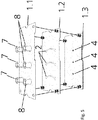
- the openings in the laminate 1.2, which forms the second laminate from above in the assembled stack, the arcuate openings are formed as channels 2, in which cells can be cultivated or biomolecules can be examined.
- actuators or combinations of Sensors with actuators are inserted into an opening and, if necessary, fixed in it.
- the recesses 5 on the end faces, as well as the positioning holes 5 of the laminates 1.1 to 1.5 can be used for an adjustment and positioning before and during the joining of the system.
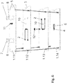
- the sensors 4 are inserted into the openings provided for the laminates 1.3 and 1.4.
- electrical conductor tracks 6 are printed on the surface of the laminate 1.4 in such a way that an electrically conductive connection of the sensors 4 to the outside or to a flexibly deformable printed circuit board, not shown here but integrated in the laminate stack, can be achieved via electrical vias 10 .
- the electrical feedthroughs 10 can be filled with an electrically conductive material or on the inner walls electrically conductive coated openings, which were also formed in the laminates, are produced.
- FIG. 4 the process of sensor embedding and the production of vias 10 is shown.
- an electrically contacted sensor structure with vias 10 is formed, which are designed downwards to contact the respective sensor 4 from the underside, for example via elastically deformable electrically conductive contact elements.
- the sensor 4 itself is embedded between the laminates formed with laminates and is in direct contact with the channel 2 and the liquid guided therein.
- the printed electrical Antitle isten 6 of the sensor 4 are sintered at temperatures just below the glass transition temperature of the laminates (1.1, .... 1.5) under pressure in the hot press 9 in order to achieve improved electrical conductivity.
- Laminate 1.1 shown above, there are openings for a respective inflow 7 and an outflow 8.
- the inflow 7 may be a liquid, which is a suitable for the cultivation of living cells liquid containing optionally one or more active ingredient (s) can be and / or a liquid in which living cells or biomolecules are contained can be introduced.
- the inflows and outflows 7 and 8 are fluid-tightly and materially connected to the laminate 1.1 and arranged so that they are each in contact with a front end of a channel 2 formed in the laminate 1.2.
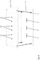
- openings 3 are formed in the sensors 4 not shown here are used, but as in the Figures 2 and 3 is shown.
- the stack thus obtained is inserted into a hot press 9.
- a thermal treatment was carried out in which the laminates are bonded together at a maximum temperature of 70 ° C - 200 ° C cohesively. This ensures that the liquid contained in the channels 2 can not escape except from inflow or outflow 7 or 8.
- the particles may consist of, for example, silver, gold, platinum, copper or alloys thereof.
- an electrochemical sensor eg for measuring the oxygen content.
- This consists of 4 laminates 1.10 - 1.14, wherein the lowest layer 1.14 contains the electrochemical sensor 4, analogous to FIG. 3 is electrically contacted by printed electrical conductors 5. Above it is in laminate 1.13 a microchannel 2 introduced, in which there is an electrolyte. The electrolyte is separated from the respective material to be measured in the laminate 1.12 by an inserted membrane 12. This membrane 12 is permeable to oxygen but impermeable to the electrolyte and is inserted directly into the composite with.
- the laminates 1.11-1.13 contain outbreaks for the electrical contacting of the sensor 4, which can be connected by means of a pin header 11 in the uppermost laminate 1.11 with the peripheral electronics. Both the electrolyte and the material to be measured (eg culture medium) can be exchanged or specifically supplied via the fluid inlets 7 and 8.
- FIG. 7 a further embodiment of the invention in the form of a pressure sensor.
- the microchannel 2 is closed by a flexible membrane 13 at the top, are applied to the printed structures 5.1.
- These preferably electrically conductive printed structures 5.1 can be used by selecting a piezoresistive ink for the realization of a DehnmessstMails and thus for measuring the diaphragm deflection or the pressure in the channel 2.
Landscapes
- Chemical & Material Sciences (AREA)
- Health & Medical Sciences (AREA)
- Life Sciences & Earth Sciences (AREA)
- Engineering & Computer Science (AREA)
- Wood Science & Technology (AREA)
- Organic Chemistry (AREA)
- Bioinformatics & Cheminformatics (AREA)
- Zoology (AREA)
- Genetics & Genomics (AREA)
- Biotechnology (AREA)
- Microbiology (AREA)
- Biomedical Technology (AREA)
- Sustainable Development (AREA)
- Biochemistry (AREA)
- General Engineering & Computer Science (AREA)
- General Health & Medical Sciences (AREA)
- Cell Biology (AREA)
- Analytical Chemistry (AREA)
- Clinical Laboratory Science (AREA)
- Physics & Mathematics (AREA)
- Thermal Sciences (AREA)
- Dispersion Chemistry (AREA)
- Apparatus Associated With Microorganisms And Enzymes (AREA)
Applications Claiming Priority (1)
| Application Number | Priority Date | Filing Date | Title |
|---|---|---|---|
| DE102017205978.8A DE102017205978B4 (de) | 2017-04-07 | 2017-04-07 | Mikrofluidisches System zur Kultivierung von oder der Analyse an lebenden Zellen oder Biomolekülen sowie ein Verfahren zu seiner Herstellung |
Publications (2)
| Publication Number | Publication Date |
|---|---|
| EP3385367A1 true EP3385367A1 (fr) | 2018-10-10 |
| EP3385367B1 EP3385367B1 (fr) | 2022-05-04 |
Family
ID=61906758
Family Applications (1)
| Application Number | Title | Priority Date | Filing Date |
|---|---|---|---|
| EP18165888.1A Active EP3385367B1 (fr) | 2017-04-07 | 2018-04-05 | Système microfluidique de culture ou d'analyse de cellules vivantes ou de biomolécules ainsi qu'un procédé de fabrication dudit système microfluidique |
Country Status (2)
| Country | Link |
|---|---|
| EP (1) | EP3385367B1 (fr) |
| DE (1) | DE102017205978B4 (fr) |
Families Citing this family (2)
| Publication number | Priority date | Publication date | Assignee | Title |
|---|---|---|---|---|
| DE102020216542A1 (de) | 2020-12-23 | 2022-06-23 | Robert Bosch Gesellschaft mit beschränkter Haftung | Membran für eine mikrofluidische Kartusche mit Ausnehmungen für einen Mikrokanal oder ein Sensorelement und Verfahren zur Herstellung einer Membran und einer Kartusche mit Membran |
| DE102022113631A1 (de) | 2022-05-31 | 2023-11-30 | Robert Bosch Gesellschaft mit beschränkter Haftung | Analysesystem mit mikrofluidischer Analysevorrichtung und mikrofluidischer Kartusche |
Citations (5)
| Publication number | Priority date | Publication date | Assignee | Title |
|---|---|---|---|---|
| US20050106066A1 (en) * | 2003-01-14 | 2005-05-19 | Micronics, Inc. | Microfluidic devices for fluid manipulation and analysis |
| US20060154361A1 (en) * | 2002-08-27 | 2006-07-13 | Wikswo John P | Bioreactors with substance injection capacity |
| DE102007046305A1 (de) * | 2007-09-27 | 2009-04-02 | Robert Bosch Gmbh | Mikrofluidisches Bauelement sowie Herstellungsverfahren |
| DE102010038445A1 (de) * | 2010-07-27 | 2012-02-02 | Robert Bosch Gmbh | Verfahren zur Herstellung eines mikrofluidischen Systems |
| DE102012102021A1 (de) * | 2012-03-09 | 2013-09-12 | Epcos Ag | Mikromechanisches Messelement und Verfahren zur Herstellung eines mikromechanischen Messelements |
Family Cites Families (1)
| Publication number | Priority date | Publication date | Assignee | Title |
|---|---|---|---|---|
| US9012255B1 (en) | 2010-10-27 | 2015-04-21 | Dunan Microstaq, Inc. | MEMS package |
-
2017
- 2017-04-07 DE DE102017205978.8A patent/DE102017205978B4/de not_active Expired - Fee Related
-
2018
- 2018-04-05 EP EP18165888.1A patent/EP3385367B1/fr active Active
Patent Citations (5)
| Publication number | Priority date | Publication date | Assignee | Title |
|---|---|---|---|---|
| US20060154361A1 (en) * | 2002-08-27 | 2006-07-13 | Wikswo John P | Bioreactors with substance injection capacity |
| US20050106066A1 (en) * | 2003-01-14 | 2005-05-19 | Micronics, Inc. | Microfluidic devices for fluid manipulation and analysis |
| DE102007046305A1 (de) * | 2007-09-27 | 2009-04-02 | Robert Bosch Gmbh | Mikrofluidisches Bauelement sowie Herstellungsverfahren |
| DE102010038445A1 (de) * | 2010-07-27 | 2012-02-02 | Robert Bosch Gmbh | Verfahren zur Herstellung eines mikrofluidischen Systems |
| DE102012102021A1 (de) * | 2012-03-09 | 2013-09-12 | Epcos Ag | Mikromechanisches Messelement und Verfahren zur Herstellung eines mikromechanischen Messelements |
Non-Patent Citations (2)
| Title |
|---|
| ROSANNE M GUIJT ET AL: "Microfluidic chips for capillary electrophoresis with integrated electrodes for capacitively coupled conductivity detection based on printed circuit board technology", SENSORS AND ACTUATORS B: CHEMICAL: INTERNATIONAL JOURNAL DEVOTED TO RESEARCH AND DEVELOPMENT OF PHYSICAL AND CHEMICAL TRANSDUCERS, ELSEVIER BV, NL, vol. 159, no. 1, 6 June 2011 (2011-06-06), pages 307 - 313, XP028280401, ISSN: 0925-4005, [retrieved on 20110612], DOI: 10.1016/J.SNB.2011.06.023 * |
| SAMUEL CHARLOT ET AL: "NOTE; A low cost and hybrid technology for integrating silicon sensors or actuators in polymer microfluidic systems", JOURNAL OF MICROMECHANICS & MICROENGINEERING, INSTITUTE OF PHYSICS PUBLISHING, BRISTOL, GB, vol. 18, no. 1, 31 January 2008 (2008-01-31), pages 17003, XP020129958, ISSN: 0960-1317 * |
Also Published As
| Publication number | Publication date |
|---|---|
| DE102017205978B4 (de) | 2021-11-04 |
| DE102017205978A1 (de) | 2018-10-11 |
| EP3385367B1 (fr) | 2022-05-04 |
Similar Documents
| Publication | Publication Date | Title |
|---|---|---|
| EP1654065B1 (fr) | Cuve a circulation constituee de couches et de systemes de liaison | |
| DE102010002915B4 (de) | Mikrofluidischer Sensor | |
| EP2394156B1 (fr) | Ensemble et procédé pour la mesure électrochimique de réactions biochimiques et procédé de fabrication de l'ensemble | |
| EP1218105B1 (fr) | Substrat de reaction structure | |
| EP3140390B1 (fr) | Demi-produit et dispositif pour la production in vitro et la culture de couches cellulaires | |
| DE102007044889B4 (de) | Diagnosetestsystem | |
| EP3024920A1 (fr) | Dispositifs, systèmes et procédés d'électrophysiologie à haut rendement | |
| DE102011078961A1 (de) | System zum Separieren von Körperflüssigkeitsbestandteilen und Verfahren zum Herstellen eines derartigen Systems | |
| EP3143119B1 (fr) | Procédé et dispositif pour traiter un échantillon de matière biologique et systeme d'analyse d'un échantillon de matière biologique | |
| EP2928606B1 (fr) | Manipulation d'objets dans des dispositifs micro-fluidiques au moyen d'électrodes externes | |
| EP3646029B1 (fr) | Système de détection et procédé pour sa fabrication | |
| EP3385367B1 (fr) | Système microfluidique de culture ou d'analyse de cellules vivantes ou de biomolécules ainsi qu'un procédé de fabrication dudit système microfluidique | |
| EP1591780B1 (fr) | Capteur pour la détection des fluides, et dispositif de détection comprenant ce capteur | |
| EP2044438A2 (fr) | Installation pour des mesures en ligne sur des cellules | |
| Kundu et al. | Multimodal microfluidic biosensor with interdigitated electrodes (IDE) and microelectrode array (MEA) for bacterial detection and identification | |
| DE102010038445A1 (de) | Verfahren zur Herstellung eines mikrofluidischen Systems | |
| EP1489404A1 (fr) | Méthode de production d'une cellule d'écoulement 3-D pour microscope | |
| WO2017129340A1 (fr) | Cellule à circulation microfluidique à électrode intégrée et son procédé de fabrication | |
| DE19851644B4 (de) | Verfahren zum Verbinden von mikrostrukturierten Werkstücken aus Kunststoff sowie Verwendung des Verfahrens zur Herstellung von Bauteilen | |
| EP2243024B1 (fr) | Dispositif et procédé pour détecter des liquides ou des substances de liquides | |
| JP4821319B2 (ja) | 細胞電気生理センサアレイおよびその製造方法 | |
| DE10022772C1 (de) | Durchflußmeßsystem | |
| DE10320898A1 (de) | Biokompatible Sensorelektrodenanordnung und Verfahren zu deren Herstellung | |
| DE102004062923A1 (de) | Vorrichtung zur Förderung von Fluiden, Verfahren zur Herstellung derselben und Pipette mit einer solchen Vorrichtung | |
| DE102007034935B4 (de) | Anordnung für Online-Messungen an Zellen |
Legal Events
| Date | Code | Title | Description |
|---|---|---|---|
| PUAI | Public reference made under article 153(3) epc to a published international application that has entered the european phase |
Free format text: ORIGINAL CODE: 0009012 |
|
| STAA | Information on the status of an ep patent application or granted ep patent |
Free format text: STATUS: THE APPLICATION HAS BEEN PUBLISHED |
|
| AK | Designated contracting states |
Kind code of ref document: A1 Designated state(s): AL AT BE BG CH CY CZ DE DK EE ES FI FR GB GR HR HU IE IS IT LI LT LU LV MC MK MT NL NO PL PT RO RS SE SI SK SM TR |
|
| AX | Request for extension of the european patent |
Extension state: BA ME |
|
| STAA | Information on the status of an ep patent application or granted ep patent |
Free format text: STATUS: REQUEST FOR EXAMINATION WAS MADE |
|
| 17P | Request for examination filed |
Effective date: 20190408 |
|
| RBV | Designated contracting states (corrected) |
Designated state(s): AL AT BE BG CH CY CZ DE DK EE ES FI FR GB GR HR HU IE IS IT LI LT LU LV MC MK MT NL NO PL PT RO RS SE SI SK SM TR |
|
| GRAP | Despatch of communication of intention to grant a patent |
Free format text: ORIGINAL CODE: EPIDOSNIGR1 |
|
| STAA | Information on the status of an ep patent application or granted ep patent |
Free format text: STATUS: GRANT OF PATENT IS INTENDED |
|
| INTG | Intention to grant announced |
Effective date: 20211109 |
|
| GRAS | Grant fee paid |
Free format text: ORIGINAL CODE: EPIDOSNIGR3 |
|
| GRAA | (expected) grant |
Free format text: ORIGINAL CODE: 0009210 |
|
| STAA | Information on the status of an ep patent application or granted ep patent |
Free format text: STATUS: THE PATENT HAS BEEN GRANTED |
|
| RAP3 | Party data changed (applicant data changed or rights of an application transferred) |
Owner name: FRAUNHOFER-GESELLSCHAFT ZUR FOERDERUNG DER ANGEWANDTEN FORSCHUNG E.V. |
|
| AK | Designated contracting states |
Kind code of ref document: B1 Designated state(s): AL AT BE BG CH CY CZ DE DK EE ES FI FR GB GR HR HU IE IS IT LI LT LU LV MC MK MT NL NO PL PT RO RS SE SI SK SM TR |
|
| REG | Reference to a national code |
Ref country code: GB Ref legal event code: FG4D Free format text: NOT ENGLISH |
|
| REG | Reference to a national code |
Ref country code: CH Ref legal event code: EP |
|
| REG | Reference to a national code |
Ref country code: AT Ref legal event code: REF Ref document number: 1489084 Country of ref document: AT Kind code of ref document: T Effective date: 20220515 |
|
| REG | Reference to a national code |
Ref country code: DE Ref legal event code: R096 Ref document number: 502018009538 Country of ref document: DE |
|
| REG | Reference to a national code |
Ref country code: IE Ref legal event code: FG4D Free format text: LANGUAGE OF EP DOCUMENT: GERMAN |
|
| REG | Reference to a national code |
Ref country code: LT Ref legal event code: MG9D |
|
| REG | Reference to a national code |
Ref country code: NL Ref legal event code: MP Effective date: 20220504 |
|
| PG25 | Lapsed in a contracting state [announced via postgrant information from national office to epo] |
Ref country code: SE Free format text: LAPSE BECAUSE OF FAILURE TO SUBMIT A TRANSLATION OF THE DESCRIPTION OR TO PAY THE FEE WITHIN THE PRESCRIBED TIME-LIMIT Effective date: 20220504 Ref country code: PT Free format text: LAPSE BECAUSE OF FAILURE TO SUBMIT A TRANSLATION OF THE DESCRIPTION OR TO PAY THE FEE WITHIN THE PRESCRIBED TIME-LIMIT Effective date: 20220905 Ref country code: NO Free format text: LAPSE BECAUSE OF FAILURE TO SUBMIT A TRANSLATION OF THE DESCRIPTION OR TO PAY THE FEE WITHIN THE PRESCRIBED TIME-LIMIT Effective date: 20220804 Ref country code: NL Free format text: LAPSE BECAUSE OF FAILURE TO SUBMIT A TRANSLATION OF THE DESCRIPTION OR TO PAY THE FEE WITHIN THE PRESCRIBED TIME-LIMIT Effective date: 20220504 Ref country code: LT Free format text: LAPSE BECAUSE OF FAILURE TO SUBMIT A TRANSLATION OF THE DESCRIPTION OR TO PAY THE FEE WITHIN THE PRESCRIBED TIME-LIMIT Effective date: 20220504 Ref country code: HR Free format text: LAPSE BECAUSE OF FAILURE TO SUBMIT A TRANSLATION OF THE DESCRIPTION OR TO PAY THE FEE WITHIN THE PRESCRIBED TIME-LIMIT Effective date: 20220504 Ref country code: GR Free format text: LAPSE BECAUSE OF FAILURE TO SUBMIT A TRANSLATION OF THE DESCRIPTION OR TO PAY THE FEE WITHIN THE PRESCRIBED TIME-LIMIT Effective date: 20220805 Ref country code: FI Free format text: LAPSE BECAUSE OF FAILURE TO SUBMIT A TRANSLATION OF THE DESCRIPTION OR TO PAY THE FEE WITHIN THE PRESCRIBED TIME-LIMIT Effective date: 20220504 Ref country code: ES Free format text: LAPSE BECAUSE OF FAILURE TO SUBMIT A TRANSLATION OF THE DESCRIPTION OR TO PAY THE FEE WITHIN THE PRESCRIBED TIME-LIMIT Effective date: 20220504 Ref country code: BG Free format text: LAPSE BECAUSE OF FAILURE TO SUBMIT A TRANSLATION OF THE DESCRIPTION OR TO PAY THE FEE WITHIN THE PRESCRIBED TIME-LIMIT Effective date: 20220804 |
|
| PG25 | Lapsed in a contracting state [announced via postgrant information from national office to epo] |
Ref country code: RS Free format text: LAPSE BECAUSE OF FAILURE TO SUBMIT A TRANSLATION OF THE DESCRIPTION OR TO PAY THE FEE WITHIN THE PRESCRIBED TIME-LIMIT Effective date: 20220504 Ref country code: PL Free format text: LAPSE BECAUSE OF FAILURE TO SUBMIT A TRANSLATION OF THE DESCRIPTION OR TO PAY THE FEE WITHIN THE PRESCRIBED TIME-LIMIT Effective date: 20220504 Ref country code: LV Free format text: LAPSE BECAUSE OF FAILURE TO SUBMIT A TRANSLATION OF THE DESCRIPTION OR TO PAY THE FEE WITHIN THE PRESCRIBED TIME-LIMIT Effective date: 20220504 Ref country code: IS Free format text: LAPSE BECAUSE OF FAILURE TO SUBMIT A TRANSLATION OF THE DESCRIPTION OR TO PAY THE FEE WITHIN THE PRESCRIBED TIME-LIMIT Effective date: 20220904 |
|
| PG25 | Lapsed in a contracting state [announced via postgrant information from national office to epo] |
Ref country code: SM Free format text: LAPSE BECAUSE OF FAILURE TO SUBMIT A TRANSLATION OF THE DESCRIPTION OR TO PAY THE FEE WITHIN THE PRESCRIBED TIME-LIMIT Effective date: 20220504 Ref country code: SK Free format text: LAPSE BECAUSE OF FAILURE TO SUBMIT A TRANSLATION OF THE DESCRIPTION OR TO PAY THE FEE WITHIN THE PRESCRIBED TIME-LIMIT Effective date: 20220504 Ref country code: RO Free format text: LAPSE BECAUSE OF FAILURE TO SUBMIT A TRANSLATION OF THE DESCRIPTION OR TO PAY THE FEE WITHIN THE PRESCRIBED TIME-LIMIT Effective date: 20220504 Ref country code: EE Free format text: LAPSE BECAUSE OF FAILURE TO SUBMIT A TRANSLATION OF THE DESCRIPTION OR TO PAY THE FEE WITHIN THE PRESCRIBED TIME-LIMIT Effective date: 20220504 Ref country code: DK Free format text: LAPSE BECAUSE OF FAILURE TO SUBMIT A TRANSLATION OF THE DESCRIPTION OR TO PAY THE FEE WITHIN THE PRESCRIBED TIME-LIMIT Effective date: 20220504 Ref country code: CZ Free format text: LAPSE BECAUSE OF FAILURE TO SUBMIT A TRANSLATION OF THE DESCRIPTION OR TO PAY THE FEE WITHIN THE PRESCRIBED TIME-LIMIT Effective date: 20220504 |
|
| REG | Reference to a national code |
Ref country code: DE Ref legal event code: R097 Ref document number: 502018009538 Country of ref document: DE |
|
| PLBE | No opposition filed within time limit |
Free format text: ORIGINAL CODE: 0009261 |
|
| STAA | Information on the status of an ep patent application or granted ep patent |
Free format text: STATUS: NO OPPOSITION FILED WITHIN TIME LIMIT |
|
| PG25 | Lapsed in a contracting state [announced via postgrant information from national office to epo] |
Ref country code: AL Free format text: LAPSE BECAUSE OF FAILURE TO SUBMIT A TRANSLATION OF THE DESCRIPTION OR TO PAY THE FEE WITHIN THE PRESCRIBED TIME-LIMIT Effective date: 20220504 |
|
| 26N | No opposition filed |
Effective date: 20230207 |
|
| PG25 | Lapsed in a contracting state [announced via postgrant information from national office to epo] |
Ref country code: SI Free format text: LAPSE BECAUSE OF FAILURE TO SUBMIT A TRANSLATION OF THE DESCRIPTION OR TO PAY THE FEE WITHIN THE PRESCRIBED TIME-LIMIT Effective date: 20220504 |
|
| P01 | Opt-out of the competence of the unified patent court (upc) registered |
Effective date: 20230524 |
|
| REG | Reference to a national code |
Ref country code: CH Ref legal event code: PL |
|
| GBPC | Gb: european patent ceased through non-payment of renewal fee |
Effective date: 20230405 |
|
| PG25 | Lapsed in a contracting state [announced via postgrant information from national office to epo] |
Ref country code: LU Free format text: LAPSE BECAUSE OF NON-PAYMENT OF DUE FEES Effective date: 20230405 |
|
| REG | Reference to a national code |
Ref country code: BE Ref legal event code: MM Effective date: 20230430 |
|
| PG25 | Lapsed in a contracting state [announced via postgrant information from national office to epo] |
Ref country code: MC Free format text: LAPSE BECAUSE OF FAILURE TO SUBMIT A TRANSLATION OF THE DESCRIPTION OR TO PAY THE FEE WITHIN THE PRESCRIBED TIME-LIMIT Effective date: 20220504 |
|
| PG25 | Lapsed in a contracting state [announced via postgrant information from national office to epo] |
Ref country code: GB Free format text: LAPSE BECAUSE OF NON-PAYMENT OF DUE FEES Effective date: 20230405 |
|
| PG25 | Lapsed in a contracting state [announced via postgrant information from national office to epo] |
Ref country code: MC Free format text: LAPSE BECAUSE OF FAILURE TO SUBMIT A TRANSLATION OF THE DESCRIPTION OR TO PAY THE FEE WITHIN THE PRESCRIBED TIME-LIMIT Effective date: 20220504 Ref country code: LI Free format text: LAPSE BECAUSE OF NON-PAYMENT OF DUE FEES Effective date: 20230430 Ref country code: IT Free format text: LAPSE BECAUSE OF FAILURE TO SUBMIT A TRANSLATION OF THE DESCRIPTION OR TO PAY THE FEE WITHIN THE PRESCRIBED TIME-LIMIT Effective date: 20220504 Ref country code: GB Free format text: LAPSE BECAUSE OF NON-PAYMENT OF DUE FEES Effective date: 20230405 Ref country code: FR Free format text: LAPSE BECAUSE OF NON-PAYMENT OF DUE FEES Effective date: 20230430 Ref country code: CH Free format text: LAPSE BECAUSE OF NON-PAYMENT OF DUE FEES Effective date: 20230430 |
|
| REG | Reference to a national code |
Ref country code: IE Ref legal event code: MM4A |
|
| PG25 | Lapsed in a contracting state [announced via postgrant information from national office to epo] |
Ref country code: BE Free format text: LAPSE BECAUSE OF NON-PAYMENT OF DUE FEES Effective date: 20230430 |
|
| PG25 | Lapsed in a contracting state [announced via postgrant information from national office to epo] |
Ref country code: IE Free format text: LAPSE BECAUSE OF NON-PAYMENT OF DUE FEES Effective date: 20230405 |
|
| PG25 | Lapsed in a contracting state [announced via postgrant information from national office to epo] |
Ref country code: IE Free format text: LAPSE BECAUSE OF NON-PAYMENT OF DUE FEES Effective date: 20230405 |
|
| REG | Reference to a national code |
Ref country code: AT Ref legal event code: MM01 Ref document number: 1489084 Country of ref document: AT Kind code of ref document: T Effective date: 20230405 |
|
| PG25 | Lapsed in a contracting state [announced via postgrant information from national office to epo] |
Ref country code: AT Free format text: LAPSE BECAUSE OF NON-PAYMENT OF DUE FEES Effective date: 20230405 |
|
| PG25 | Lapsed in a contracting state [announced via postgrant information from national office to epo] |
Ref country code: AT Free format text: LAPSE BECAUSE OF NON-PAYMENT OF DUE FEES Effective date: 20230405 |
|
| PG25 | Lapsed in a contracting state [announced via postgrant information from national office to epo] |
Ref country code: BG Free format text: LAPSE BECAUSE OF FAILURE TO SUBMIT A TRANSLATION OF THE DESCRIPTION OR TO PAY THE FEE WITHIN THE PRESCRIBED TIME-LIMIT Effective date: 20220504 |
|
| PG25 | Lapsed in a contracting state [announced via postgrant information from national office to epo] |
Ref country code: BG Free format text: LAPSE BECAUSE OF FAILURE TO SUBMIT A TRANSLATION OF THE DESCRIPTION OR TO PAY THE FEE WITHIN THE PRESCRIBED TIME-LIMIT Effective date: 20220504 |
|
| PGFP | Annual fee paid to national office [announced via postgrant information from national office to epo] |
Ref country code: DE Payment date: 20250417 Year of fee payment: 8 |
|
| PG25 | Lapsed in a contracting state [announced via postgrant information from national office to epo] |
Ref country code: CY Free format text: LAPSE BECAUSE OF FAILURE TO SUBMIT A TRANSLATION OF THE DESCRIPTION OR TO PAY THE FEE WITHIN THE PRESCRIBED TIME-LIMIT; INVALID AB INITIO Effective date: 20180405 |
|
| PG25 | Lapsed in a contracting state [announced via postgrant information from national office to epo] |
Ref country code: HU Free format text: LAPSE BECAUSE OF FAILURE TO SUBMIT A TRANSLATION OF THE DESCRIPTION OR TO PAY THE FEE WITHIN THE PRESCRIBED TIME-LIMIT; INVALID AB INITIO Effective date: 20180405 |
|
| PG25 | Lapsed in a contracting state [announced via postgrant information from national office to epo] |
Ref country code: TR Free format text: LAPSE BECAUSE OF FAILURE TO SUBMIT A TRANSLATION OF THE DESCRIPTION OR TO PAY THE FEE WITHIN THE PRESCRIBED TIME-LIMIT Effective date: 20220504 |