EP3385452A1 - Recycleuse de chaussées pourvue d'un carter de retenue des aubes - Google Patents
Recycleuse de chaussées pourvue d'un carter de retenue des aubes Download PDFInfo
- Publication number
- EP3385452A1 EP3385452A1 EP18165806.3A EP18165806A EP3385452A1 EP 3385452 A1 EP3385452 A1 EP 3385452A1 EP 18165806 A EP18165806 A EP 18165806A EP 3385452 A1 EP3385452 A1 EP 3385452A1
- Authority
- EP
- European Patent Office
- Prior art keywords
- piece
- housing
- end piece
- bolt
- shaft
- Prior art date
- Legal status (The legal status is an assumption and is not a legal conclusion. Google has not performed a legal analysis and makes no representation as to the accuracy of the status listed.)
- Granted
Links
Images


Classifications
-
- E—FIXED CONSTRUCTIONS
- E02—HYDRAULIC ENGINEERING; FOUNDATIONS; SOIL SHIFTING
- E02F—DREDGING; SOIL-SHIFTING
- E02F3/00—Dredgers; Soil-shifting machines
- E02F3/04—Dredgers; Soil-shifting machines mechanically-driven
- E02F3/96—Dredgers; Soil-shifting machines mechanically-driven with arrangements for alternate or simultaneous use of different digging elements
- E02F3/965—Dredgers; Soil-shifting machines mechanically-driven with arrangements for alternate or simultaneous use of different digging elements of metal-cutting or concrete-crushing implements
-
- B—PERFORMING OPERATIONS; TRANSPORTING
- B02—CRUSHING, PULVERISING, OR DISINTEGRATING; PREPARATORY TREATMENT OF GRAIN FOR MILLING
- B02C—CRUSHING, PULVERISING, OR DISINTEGRATING IN GENERAL; MILLING GRAIN
- B02C4/00—Crushing or disintegrating by roller mills
- B02C4/28—Details
-
- E—FIXED CONSTRUCTIONS
- E02—HYDRAULIC ENGINEERING; FOUNDATIONS; SOIL SHIFTING
- E02F—DREDGING; SOIL-SHIFTING
- E02F3/00—Dredgers; Soil-shifting machines
- E02F3/04—Dredgers; Soil-shifting machines mechanically-driven
- E02F3/28—Dredgers; Soil-shifting machines mechanically-driven with digging tools mounted on a dipper- or bucket-arm, i.e. there is either one arm or a pair of arms, e.g. dippers, buckets
- E02F3/36—Component parts
- E02F3/40—Dippers; Buckets ; Grab devices, e.g. manufacturing processes for buckets, form, geometry or material of buckets
- E02F3/407—Dippers; Buckets ; Grab devices, e.g. manufacturing processes for buckets, form, geometry or material of buckets with ejecting or other unloading device
-
- E—FIXED CONSTRUCTIONS
- E02—HYDRAULIC ENGINEERING; FOUNDATIONS; SOIL SHIFTING
- E02F—DREDGING; SOIL-SHIFTING
- E02F7/00—Equipment for conveying or separating excavated material
- E02F7/06—Delivery chutes or screening plants or mixing plants mounted on dredgers or excavators
-
- B—PERFORMING OPERATIONS; TRANSPORTING
- B07—SEPARATING SOLIDS FROM SOLIDS; SORTING
- B07B—SEPARATING SOLIDS FROM SOLIDS BY SIEVING, SCREENING, SIFTING OR BY USING GAS CURRENTS; SEPARATING BY OTHER DRY METHODS APPLICABLE TO BULK MATERIAL, e.g. LOOSE ARTICLES FIT TO BE HANDLED LIKE BULK MATERIAL
- B07B1/00—Sieving, screening, sifting, or sorting solid materials using networks, gratings, grids, or the like
- B07B1/12—Apparatus having only parallel elements
- B07B1/14—Roller screens
- B07B1/15—Roller screens using corrugated, grooved or ribbed rollers
Definitions
- the invention relates to a Bodenrecycler with a blade housing and arranged on a housing front receiving opening and arranged on an opposite rear housing outlet for recycle, in particular to be crushed and / or screened and / or mixed material and a Bodenrecycle driving in the housing is received, wherein the Bodenrecycle driving comprises at least one recycle-carrying waves, and wherein the shaft has a central piece and at least one end piece mounted in the housing, which adjoin one another in the axial direction and non-rotatably with each other are connectable, and in which the middle piece is removably mounted in the housing.
- Such devices are known in the art and, for example, in the DE 10 2012 010 215 A1 described in which a removable shaft of a crusher is disclosed, in which a center piece is coupled to an end piece via a tongue and groove joint in a parting plane, to ensure a separability and at the same time a transmission of the rotation.
- the disadvantage here is that there is always the risk that it comes in the area of the interface to contamination, which then make it difficult to separate the tongue and groove connection.
- the EP 2 631 371 B1 a Siebschaufel with a connection of output to shaft via a Einsteckschnellitati, in which case a bearing housing is attached to the actual blade housing by means of screw and the bearing housing must be removed to change the waves, then the waves that protrude with a pin in the bearing housing, to be able to remove.
- the invention solves this problem by a Bodenrecycler with the features of claim 1, wherein the center piece and the end of the shaft in a housing installed state aligned axial inner holes, in which a center piece with the at least one end piece connecting removable for removing the shaft removable bolt from the middle piece opposite side of the tail is inserted, which has at least partially profiling on its lateral surface, which cooperates with a corresponding profiling of the inner bore of the center piece and the end piece for transmitting torque.
- a removability of the at least one shaft can be achieved particularly easily, wherein preferably more than one shaft are provided, which cooperate with one another such that the recycling means provided on the shafts, in particular disks and / or cams, are involved , cooperate for recycling, in particular for comminution or screening or mixing of the material to be comminuted or to be screened or mixed, and in particular combing with each other.
- the present invention makes it possible for this part of the waves, provided with the recyclates, to be unproblematically separated from the soil recycler in order, for example, to be subjected to a repair or overhaul or, for example, to exchange a soil recycling device (crushing device) for another (screening device).
- Such Bodenrecycler be used in the rule as attachments for construction equipment, such as excavators, where it may be particularly advantageous if the Bodenrecycler with a coupling device, in particular a quick-change device, as is common in the field of construction machines, connectable and so with the hydraulics of a construction machine, such as an excavator, connectable and drivable and movable over this.
- a coupling device in particular a quick-change device
- the shafts of the soil recycling device are rotated from at least one side by a drive in rotation, wherein the rotation is transmitted from the tail to the center of the shaft.
- a chain drive is provided as a rule, which allows the simultaneous drive of multiple waves in a simple manner, since a bottom recycle device usually includes more than one shaft.
- such drives are relatively robust.
- end pieces are at both ends of a respective shaft provided, which are mounted in the housing and wherein the end pieces with the central piece rotationally fixed, in particular via a bolt coupled.
- the end piece and the middle piece preferably adjoin one another in the axial direction of the shaft and more preferably bear against one another.
- the center piece can be removed through the outlet opening and corresponds in particular to its dimensions of the dimension of the outlet opening.
- a bolt which can be inserted into the shaft from the side of the end piece and rotatably connects the center piece with the end piece.
- a torque transmission is provided on the one hand and on the other hand in a simple manner pulling out of the bolt from the side facing away from the center allows the tail ago.
- a profiling z As a square profile, but preferably a wave profile in cross section, in question, wherein the profiling is preferably arranged parallel over the circumference and extends over the entire length.
- the housing of the floor reclaiming device has, for example on its side walls, closable openings preferably by means of a cover, which provide accessibility and allow removability of the bolt.
- Other openings may, for example, allow accessibility of the drive or bearings.
- the bolt has an inner bore for receiving a locking screw.
- the locking screw lies with its screw head indirectly or directly against a centerpiece in the axial direction facing away from the surface of the tail.
- the inner bore may be formed as a blind hole and have a thread for screwing in the locking screw.
- the locking screw can pass through the bolt and is then screwed in particular with its other end in the middle piece.
- the bolt can be securely fixed in the tail or in the middle piece.
- the provision of a bolt passing through the locking screw allows the adjustment of the separation gap between tail and center piece and thus the exact positioning of at least one, but in particular several waves in the housing and at the same time the waves to each other.
- the end facing away from the screw head is fixed, for example in the middle piece.
- the locking screw acts like a tie rod. The distance between the center piece and the end piece on the side on which a locking screw is provided can thus be conclusive be fixed.
- the locking screw which is either screwed into the bolt or inserted through the bolt and then in particular is not connected to this, preferably has an external thread, this external thread need not be provided over the entire length of the locking screw, but a thread, for example. is sufficient only in the region of the end of the screw, which faces away from the screw head.
- both variants can be used at different ends of the shaft.
- the inner bore of the respective end piece is at least partially covered on the side facing away from the middle piece by means of a cover plate, the cover plate being fixed to the respective end piece via screw connections can be.
- the cover plate also has an opening which is arranged in particular centrally to prevent an imbalance to the rotating parts and this opening then by the locking screw (if provided) can be penetrated. It is also possible, if no locking screw is provided to use a cover plate without central opening. Furthermore, it is particularly preferred if the number of screws that serve to fix the cover plate are distributed as evenly as possible over the circumference to avoid imbalance.
- the locking screw can rest against the cover plate in this case, with a washer between the screw head and cover plate can be provided.
- an inner bore of the bolt in particular on its from the Centerpiece pioneering side has a thread.
- This can also interact with the locking screw depending on the design.
- a tool which can serve as a tool depending on the arrangement of the locking screw
- the internal thread extends only over a portion of the inner bore of the bolt.
- the center piece is multi-part and in particular consists of a shaft body and hereby rotationally fixed, in particular material-locking, connected edge-side shaft heads. It can further be provided in particular that the shaft heads cooperate on the profiling with the bolt.
- the shaft heads and the shaft body can be materially connected to each other, in particular be welded together. It may be provided to fix the position of the two elements to each other, this before the material connection, z. B. pre-fix by means of pins.
- the at least one end piece is arranged inside the housing and in particular in a gearbox or storage box of the housing.
- the middle piece is then in the area of the case back and here in the region of the outlet opening, which is provided on the rear side of the housing, through which recycled or shredded or sieved material is conveyed out of the blade again. In this way, a simple removal of the center pieces to the "back" from the outlet opening of the housing back out possible.
- a shell-shaped sealing means may particularly preferably be provided, which encloses the center piece at least in regions and is connected to the housing, in particular a bearing and / or gear housing.
- This sealing means may be formed in the manner of a labyrinth seal or cooperate with the center piece and preferably be formed from two non-positively or positively connectable half-shells.
- cup-shaped sealing means surrounds the center of the shaft, and in particular, if it is multi-part, in the region of the shaft head, is particularly preferably provided when the shaft head has at its end facing the end of a flange, which by the sealing means below Formation of a labyrinth will be covered. So that a change of the middle piece is possible without problems, the two-part cup-shaped sealing means is then first removed by the at least two shells from each other be separated. If more than two shell elements are provided, these should also be referred to in the present case with "half shells".
- the connection of the half-shells can be effected by means of a pin connection, wherein the sealing means, for example on the housing, is fixed by means of a screw connection.
- the at least one shaft is mounted in the housing, with conventional bearings can be used.
- the reclaimer is positioned so that its outlet opening provided at the rear side of the housing points downwards.
- the shaft or waves according to the invention are arranged. They are rotated by at least one drive and thereby take with their cams and / or discs parts of the material located in the Bodenrecycler and break this between their cams or discs.
- adjacent shafts preferably interact with each other in a combing manner together. This takes place until the resulting smaller parts emerge down through the intermediate spaces between the cams and / or disks of the shafts and are available there as bulk material of reduced grain size.
- a screen mesh can be used, which must also be removed before removing the at least one wave and usually penetrated by acting as a sieve bottom recycle device and here usually of discs on the at least one shaft becomes.
- Such comminution tasks are generally found in the construction sector, be it for soil, but also minerals, such as ores, coals or minerals.
- minerals such as ores, coals or minerals.
- other applications for example in the field of waste management, etc. conceivable and should be encompassed by the invention.
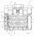
- a soil recycler according to the invention is designated by the reference numeral 10 and comprises a housing 12 with a housing front side 14 and a housing rear side 16.
- the bottom recycler 10 is shown from the rear side.
- the front of the housing in this case has an inlet not shown for recycling (to be broken and / or to be screened and / or mixed) material
- the housing rear side 16 has an outlet opening 18 for the recycled (crushed and / or screened) material.
- a Bodenrecycle driving 20 is provided in the region of the outlet opening, which in the present case comprises three shafts 22, wherein the shafts are provided with different cams 24, and the cams 24 of a shaft with the cam 24 of another shaft 22 mesh and between them recycle the goods to be recycled and transport them through.
- Such Bodenrecycler are preferably attached as attachments, for example, on a boom arm of an excavator, for this purpose on a support plate 26 a Quick change device may be provided for coupling to such a construction machine.
- FIG. 1 the bearing of the shafts 22 on the right side in the representation in a bearing housing 43 and on the left side in the representation provided in a gear and / or bearing housing 41, wherein the bearing housing 43 is shown closed at the rear of the housing 16 by a cover 45 is and the bearing housing 41 (in the drawing without cover) is shown open, so that the drive 34, which takes place here via a chain drive, at least partially can be seen.
- the drive takes place here in particular via a hydraulic system of the construction machine.
- FIG. 2 shows a sectional view of a section A from FIG. 1 , It is here to recognize the chain 36 of the drive 34. Also, the cams 24 of the shaft 22 can be seen. According to the invention, the shafts 22 can be removed from the housing 12.
- the shafts 22 have a central piece 26 and at least on the drive side, an end piece 28.
- the middle piece 26 and the end piece 28 are rotatably connected to each other.
- an end piece 28 is provided on both sides of the middle piece 26.
- the middle piece 26 here consists of a shaft body 30 and a shaft head 32, which are positioned via a pin connection 33 to each other and then connected to each other by welding.
- the end piece 28 is arranged in the bearing housing 41, whereas the middle piece 26 is located in the region of the outlet opening 18.
- On the Center piece 26 facing away (opposite) side of the bearing housing 41 are one or more covers 38 (s. FIG. 1 ) are provided for openings that allow access to the shafts 22 from the outside.
- the end piece 28 is designed so that it cooperates with the chain links of the chain 36 and for this purpose has a pinion 47 with an external toothing 46.
- the end piece 28 and the center piece 26 on an axial inner bore 48 and 50, which are aligned with each other and carry a profiling (not shown).
- a bolt 52 can be inserted, which has a corresponding profiling.
- the bolt 52 now allows the transmission of the rotation of the chain 36 via the end piece 28 on the middle piece 26 and thus the rotationally fixed connection of the two elements.
- a locking screw 54 is provided, which is inserted from the side of the end piece 28 in an inner bore 53 of the bolt 52 and has a thread 56, with which they in the bolt 52 via a corresponding thread can be screwed.
- the locking screw 54 lies with its screw head 58 facing away from the central piece 26 Side of the tail, wherein between end piece 28 and screw head 58, a washer 60 and a cover plate 62 is provided, which largely covers the inner bore 48 in the end piece 28 and thus secures the bolt 52 together with the locking screw 54 in position.
- the insertion of the bolt 52 takes place from the side of the end piece 28 ago.
- the cover plate 62 may be attached by screws 64 to the end piece 28, wherein a uniform arrangement of the screw is circumferentially preferred to avoid imbalances.
- FIG. 2 shows FIG. 2 a sealant 66 which is in FIG. 3 is shown in more detail.
- the sealant 66 is cup-shaped and overcaps, as is FIG. 2 can be seen, a flange 68 of the middle piece 26, so that there is a labyrinthine sealing path 70.
- the shell-shaped sealing means 66 consists of two half shells 72. The two half-shells can be connected to each other via pins (not shown) which engage in corresponding bores, wherein then a fixation of the sealing means 66 via a screw 75 on the bearing housing 41.
Landscapes
- Engineering & Computer Science (AREA)
- Mining & Mineral Resources (AREA)
- Structural Engineering (AREA)
- Civil Engineering (AREA)
- General Engineering & Computer Science (AREA)
- Mechanical Engineering (AREA)
- Food Science & Technology (AREA)
- Component Parts Of Construction Machinery (AREA)
- Combined Means For Separation Of Solids (AREA)
- Soil Working Implements (AREA)
Applications Claiming Priority (1)
| Application Number | Priority Date | Filing Date | Title |
|---|---|---|---|
| DE102017107352.3A DE102017107352A1 (de) | 2017-04-05 | 2017-04-05 | Bodenrecycler mit einem Schaufelgehäuse |
Publications (2)
| Publication Number | Publication Date |
|---|---|
| EP3385452A1 true EP3385452A1 (fr) | 2018-10-10 |
| EP3385452B1 EP3385452B1 (fr) | 2022-06-08 |
Family
ID=61906720
Family Applications (1)
| Application Number | Title | Priority Date | Filing Date |
|---|---|---|---|
| EP18165806.3A Active EP3385452B1 (fr) | 2017-04-05 | 2018-04-05 | Recycleuse de chaussées pourvue d'un carter de retenue des aubes |
Country Status (2)
| Country | Link |
|---|---|
| EP (1) | EP3385452B1 (fr) |
| DE (1) | DE102017107352A1 (fr) |
Cited By (3)
| Publication number | Priority date | Publication date | Assignee | Title |
|---|---|---|---|---|
| CN111545290A (zh) * | 2020-05-27 | 2020-08-18 | 陕西金磊混凝土有限公司 | 一种建筑垃圾回收分拣装置 |
| CN113083426A (zh) * | 2021-03-29 | 2021-07-09 | 安徽华然装饰设计有限责任公司 | 一种环保型用于装饰施工中的建筑废料处理装置 |
| DE102022126952B3 (de) | 2022-10-14 | 2024-04-18 | Mts Schrode Ag | Bodenrecycler mit einem Schaufelgehäuse |
Families Citing this family (1)
| Publication number | Priority date | Publication date | Assignee | Title |
|---|---|---|---|---|
| CN111514973B (zh) * | 2020-05-03 | 2021-11-19 | 大庆鑫东祥机械制造有限公司 | 一种建筑废水和建筑垃圾回收利用装置 |
Citations (4)
| Publication number | Priority date | Publication date | Assignee | Title |
|---|---|---|---|---|
| DE2837317A1 (de) * | 1978-08-26 | 1980-02-28 | Fella Werke Gmbh | Verteilwalzen an einem landwirtschaftlichen lade- bzw. erntefahrzeug |
| DE2660409B1 (de) * | 1976-07-16 | 1981-02-19 | Fahr Ag Maschf | Entladevorrichtung an einem landwirtschaftlich genutzten Fahrzeug,insbesondere einem Ladewagen |
| US20030183561A1 (en) * | 2002-03-26 | 2003-10-02 | Bollegraaf Beheer Appingedam B.V. | Separation device |
| DE102012010215A1 (de) * | 2012-05-22 | 2013-11-28 | Jürgen Wolf | Zerkleinerer mit schnell wechselbarer Messerwelle |
Family Cites Families (3)
| Publication number | Priority date | Publication date | Assignee | Title |
|---|---|---|---|---|
| US5896734A (en) * | 1997-09-02 | 1999-04-27 | Textron Inc. | Rotation drive connection for a reel mower |
| US7930872B2 (en) * | 2008-11-12 | 2011-04-26 | Alamo Group, Inc. | Drive system for a flail mower |
| ITTO20120162A1 (it) | 2012-02-24 | 2013-08-25 | Cangini Benne Srl | Benna vagliatrice |
-
2017
- 2017-04-05 DE DE102017107352.3A patent/DE102017107352A1/de not_active Ceased
-
2018
- 2018-04-05 EP EP18165806.3A patent/EP3385452B1/fr active Active
Patent Citations (4)
| Publication number | Priority date | Publication date | Assignee | Title |
|---|---|---|---|---|
| DE2660409B1 (de) * | 1976-07-16 | 1981-02-19 | Fahr Ag Maschf | Entladevorrichtung an einem landwirtschaftlich genutzten Fahrzeug,insbesondere einem Ladewagen |
| DE2837317A1 (de) * | 1978-08-26 | 1980-02-28 | Fella Werke Gmbh | Verteilwalzen an einem landwirtschaftlichen lade- bzw. erntefahrzeug |
| US20030183561A1 (en) * | 2002-03-26 | 2003-10-02 | Bollegraaf Beheer Appingedam B.V. | Separation device |
| DE102012010215A1 (de) * | 2012-05-22 | 2013-11-28 | Jürgen Wolf | Zerkleinerer mit schnell wechselbarer Messerwelle |
Cited By (3)
| Publication number | Priority date | Publication date | Assignee | Title |
|---|---|---|---|---|
| CN111545290A (zh) * | 2020-05-27 | 2020-08-18 | 陕西金磊混凝土有限公司 | 一种建筑垃圾回收分拣装置 |
| CN113083426A (zh) * | 2021-03-29 | 2021-07-09 | 安徽华然装饰设计有限责任公司 | 一种环保型用于装饰施工中的建筑废料处理装置 |
| DE102022126952B3 (de) | 2022-10-14 | 2024-04-18 | Mts Schrode Ag | Bodenrecycler mit einem Schaufelgehäuse |
Also Published As
| Publication number | Publication date |
|---|---|
| DE102017107352A1 (de) | 2018-10-11 |
| EP3385452B1 (fr) | 2022-06-08 |
Similar Documents
| Publication | Publication Date | Title |
|---|---|---|
| EP0965695B1 (fr) | Dispositif pour cribler et/ou désagréger des matériaux de criblage | |
| EP3248687B1 (fr) | Desintegrateur a deux arbres comprenant un dispositif de changement rapide | |
| EP3385452B1 (fr) | Recycleuse de chaussées pourvue d'un carter de retenue des aubes | |
| DE4311435B4 (de) | Zerkleinerungsmaschine mit Nachzerkleinerungskorb | |
| EP2374937B1 (fr) | Engin de traitement d'une surface de voie de circulation | |
| DE3301186A1 (de) | Hammermuehle mit rotor, der mit kappen versehene scheiben aufweist | |
| EP4161702B1 (fr) | Déchiqueteur à double arbre, à concept de maintenance horizontal | |
| WO2013167497A2 (fr) | Broyeuse | |
| EP1960108A1 (fr) | Rotor pour broyeur a percussion | |
| DE202021100642U1 (de) | Vorrichtung zum Zerkleinern und/oder Aufbereiten von Materialien und Verwendung einer solchen Vorrichtung | |
| EP3566777B1 (fr) | Broyeur à arbres | |
| DE3918657C2 (de) | Rotor mit Schutzkappen | |
| DE3910115C2 (fr) | ||
| DE29616319U1 (de) | Walzenbrecher | |
| EP3552693A1 (fr) | Distributeur circulaire de tamis et tôle d'usure pour le bras d'étalement d'un distributeur circulaire de tamis | |
| DE102015014225B4 (de) | Mulchgerät | |
| EP4227005B1 (fr) | Dispositif de sécurité contre les surcharges pour le système hydraulique d'une installation de traitement de matières minérales | |
| DE102022126952B3 (de) | Bodenrecycler mit einem Schaufelgehäuse | |
| AT523406A4 (de) | Zerkleinerungsmaschine | |
| DE7818838U1 (de) | Maschine zum zerkleinern von abfallstoffen | |
| DE202022002968U1 (de) | Zerkleinerungsmaschine | |
| EP4360762B1 (fr) | Dispositif de broyage | |
| DE10311918A1 (de) | Vorrichtung zum Brechen und Sieben oder Fräsen | |
| WO2022258171A1 (fr) | Appareil de transformation pour des denrées alimentaires | |
| DE102024114476B3 (de) | Zerkleinerungsvorrichtung |
Legal Events
| Date | Code | Title | Description |
|---|---|---|---|
| PUAI | Public reference made under article 153(3) epc to a published international application that has entered the european phase |
Free format text: ORIGINAL CODE: 0009012 |
|
| STAA | Information on the status of an ep patent application or granted ep patent |
Free format text: STATUS: THE APPLICATION HAS BEEN PUBLISHED |
|
| AK | Designated contracting states |
Kind code of ref document: A1 Designated state(s): AL AT BE BG CH CY CZ DE DK EE ES FI FR GB GR HR HU IE IS IT LI LT LU LV MC MK MT NL NO PL PT RO RS SE SI SK SM TR |
|
| AX | Request for extension of the european patent |
Extension state: BA ME |
|
| STAA | Information on the status of an ep patent application or granted ep patent |
Free format text: STATUS: REQUEST FOR EXAMINATION WAS MADE |
|
| 17P | Request for examination filed |
Effective date: 20190410 |
|
| RBV | Designated contracting states (corrected) |
Designated state(s): AL AT BE BG CH CY CZ DE DK EE ES FI FR GB GR HR HU IE IS IT LI LT LU LV MC MK MT NL NO PL PT RO RS SE SI SK SM TR |
|
| RAP1 | Party data changed (applicant data changed or rights of an application transferred) |
Owner name: MTS SCHRODE AG |
|
| GRAP | Despatch of communication of intention to grant a patent |
Free format text: ORIGINAL CODE: EPIDOSNIGR1 |
|
| STAA | Information on the status of an ep patent application or granted ep patent |
Free format text: STATUS: GRANT OF PATENT IS INTENDED |
|
| RIC1 | Information provided on ipc code assigned before grant |
Ipc: B07B 1/15 20060101ALI20211202BHEP Ipc: B02C 4/28 20060101ALI20211202BHEP Ipc: E02F 7/06 20060101ALI20211202BHEP Ipc: E02F 3/96 20060101ALI20211202BHEP Ipc: B02C 18/24 20060101ALI20211202BHEP Ipc: B07B 1/14 20060101ALI20211202BHEP Ipc: B02C 4/08 20060101ALI20211202BHEP Ipc: B01F 7/00 20060101ALI20211202BHEP Ipc: E02F 3/407 20060101AFI20211202BHEP |
|
| INTG | Intention to grant announced |
Effective date: 20211220 |
|
| GRAS | Grant fee paid |
Free format text: ORIGINAL CODE: EPIDOSNIGR3 |
|
| GRAA | (expected) grant |
Free format text: ORIGINAL CODE: 0009210 |
|
| STAA | Information on the status of an ep patent application or granted ep patent |
Free format text: STATUS: THE PATENT HAS BEEN GRANTED |
|
| AK | Designated contracting states |
Kind code of ref document: B1 Designated state(s): AL AT BE BG CH CY CZ DE DK EE ES FI FR GB GR HR HU IE IS IT LI LT LU LV MC MK MT NL NO PL PT RO RS SE SI SK SM TR |
|
| REG | Reference to a national code |
Ref country code: AT Ref legal event code: REF Ref document number: 1497005 Country of ref document: AT Kind code of ref document: T Effective date: 20220615 Ref country code: CH Ref legal event code: EP |
|
| REG | Reference to a national code |
Ref country code: DE Ref legal event code: R096 Ref document number: 502018009845 Country of ref document: DE |
|
| REG | Reference to a national code |
Ref country code: IE Ref legal event code: FG4D Free format text: LANGUAGE OF EP DOCUMENT: GERMAN |
|
| REG | Reference to a national code |
Ref country code: LT Ref legal event code: MG9D |
|
| REG | Reference to a national code |
Ref country code: NL Ref legal event code: MP Effective date: 20220608 |
|
| PG25 | Lapsed in a contracting state [announced via postgrant information from national office to epo] |
Ref country code: SE Free format text: LAPSE BECAUSE OF FAILURE TO SUBMIT A TRANSLATION OF THE DESCRIPTION OR TO PAY THE FEE WITHIN THE PRESCRIBED TIME-LIMIT Effective date: 20220608 Ref country code: NO Free format text: LAPSE BECAUSE OF FAILURE TO SUBMIT A TRANSLATION OF THE DESCRIPTION OR TO PAY THE FEE WITHIN THE PRESCRIBED TIME-LIMIT Effective date: 20220908 Ref country code: LT Free format text: LAPSE BECAUSE OF FAILURE TO SUBMIT A TRANSLATION OF THE DESCRIPTION OR TO PAY THE FEE WITHIN THE PRESCRIBED TIME-LIMIT Effective date: 20220608 Ref country code: HR Free format text: LAPSE BECAUSE OF FAILURE TO SUBMIT A TRANSLATION OF THE DESCRIPTION OR TO PAY THE FEE WITHIN THE PRESCRIBED TIME-LIMIT Effective date: 20220608 Ref country code: GR Free format text: LAPSE BECAUSE OF FAILURE TO SUBMIT A TRANSLATION OF THE DESCRIPTION OR TO PAY THE FEE WITHIN THE PRESCRIBED TIME-LIMIT Effective date: 20220909 Ref country code: FI Free format text: LAPSE BECAUSE OF FAILURE TO SUBMIT A TRANSLATION OF THE DESCRIPTION OR TO PAY THE FEE WITHIN THE PRESCRIBED TIME-LIMIT Effective date: 20220608 Ref country code: ES Free format text: LAPSE BECAUSE OF FAILURE TO SUBMIT A TRANSLATION OF THE DESCRIPTION OR TO PAY THE FEE WITHIN THE PRESCRIBED TIME-LIMIT Effective date: 20220608 Ref country code: BG Free format text: LAPSE BECAUSE OF FAILURE TO SUBMIT A TRANSLATION OF THE DESCRIPTION OR TO PAY THE FEE WITHIN THE PRESCRIBED TIME-LIMIT Effective date: 20220908 |
|
| PG25 | Lapsed in a contracting state [announced via postgrant information from national office to epo] |
Ref country code: RS Free format text: LAPSE BECAUSE OF FAILURE TO SUBMIT A TRANSLATION OF THE DESCRIPTION OR TO PAY THE FEE WITHIN THE PRESCRIBED TIME-LIMIT Effective date: 20220608 Ref country code: LV Free format text: LAPSE BECAUSE OF FAILURE TO SUBMIT A TRANSLATION OF THE DESCRIPTION OR TO PAY THE FEE WITHIN THE PRESCRIBED TIME-LIMIT Effective date: 20220608 |
|
| PG25 | Lapsed in a contracting state [announced via postgrant information from national office to epo] |
Ref country code: NL Free format text: LAPSE BECAUSE OF FAILURE TO SUBMIT A TRANSLATION OF THE DESCRIPTION OR TO PAY THE FEE WITHIN THE PRESCRIBED TIME-LIMIT Effective date: 20220608 |
|
| PG25 | Lapsed in a contracting state [announced via postgrant information from national office to epo] |
Ref country code: SM Free format text: LAPSE BECAUSE OF FAILURE TO SUBMIT A TRANSLATION OF THE DESCRIPTION OR TO PAY THE FEE WITHIN THE PRESCRIBED TIME-LIMIT Effective date: 20220608 Ref country code: SK Free format text: LAPSE BECAUSE OF FAILURE TO SUBMIT A TRANSLATION OF THE DESCRIPTION OR TO PAY THE FEE WITHIN THE PRESCRIBED TIME-LIMIT Effective date: 20220608 Ref country code: RO Free format text: LAPSE BECAUSE OF FAILURE TO SUBMIT A TRANSLATION OF THE DESCRIPTION OR TO PAY THE FEE WITHIN THE PRESCRIBED TIME-LIMIT Effective date: 20220608 Ref country code: PT Free format text: LAPSE BECAUSE OF FAILURE TO SUBMIT A TRANSLATION OF THE DESCRIPTION OR TO PAY THE FEE WITHIN THE PRESCRIBED TIME-LIMIT Effective date: 20221010 Ref country code: EE Free format text: LAPSE BECAUSE OF FAILURE TO SUBMIT A TRANSLATION OF THE DESCRIPTION OR TO PAY THE FEE WITHIN THE PRESCRIBED TIME-LIMIT Effective date: 20220608 Ref country code: CZ Free format text: LAPSE BECAUSE OF FAILURE TO SUBMIT A TRANSLATION OF THE DESCRIPTION OR TO PAY THE FEE WITHIN THE PRESCRIBED TIME-LIMIT Effective date: 20220608 |
|
| PG25 | Lapsed in a contracting state [announced via postgrant information from national office to epo] |
Ref country code: PL Free format text: LAPSE BECAUSE OF FAILURE TO SUBMIT A TRANSLATION OF THE DESCRIPTION OR TO PAY THE FEE WITHIN THE PRESCRIBED TIME-LIMIT Effective date: 20220608 Ref country code: IS Free format text: LAPSE BECAUSE OF FAILURE TO SUBMIT A TRANSLATION OF THE DESCRIPTION OR TO PAY THE FEE WITHIN THE PRESCRIBED TIME-LIMIT Effective date: 20221008 |
|
| REG | Reference to a national code |
Ref country code: DE Ref legal event code: R097 Ref document number: 502018009845 Country of ref document: DE |
|
| PG25 | Lapsed in a contracting state [announced via postgrant information from national office to epo] |
Ref country code: AL Free format text: LAPSE BECAUSE OF FAILURE TO SUBMIT A TRANSLATION OF THE DESCRIPTION OR TO PAY THE FEE WITHIN THE PRESCRIBED TIME-LIMIT Effective date: 20220608 |
|
| PLBE | No opposition filed within time limit |
Free format text: ORIGINAL CODE: 0009261 |
|
| STAA | Information on the status of an ep patent application or granted ep patent |
Free format text: STATUS: NO OPPOSITION FILED WITHIN TIME LIMIT |
|
| PG25 | Lapsed in a contracting state [announced via postgrant information from national office to epo] |
Ref country code: DK Free format text: LAPSE BECAUSE OF FAILURE TO SUBMIT A TRANSLATION OF THE DESCRIPTION OR TO PAY THE FEE WITHIN THE PRESCRIBED TIME-LIMIT Effective date: 20220608 |
|
| 26N | No opposition filed |
Effective date: 20230310 |
|
| PG25 | Lapsed in a contracting state [announced via postgrant information from national office to epo] |
Ref country code: SI Free format text: LAPSE BECAUSE OF FAILURE TO SUBMIT A TRANSLATION OF THE DESCRIPTION OR TO PAY THE FEE WITHIN THE PRESCRIBED TIME-LIMIT Effective date: 20220608 |
|
| REG | Reference to a national code |
Ref country code: CH Ref legal event code: PL |
|
| GBPC | Gb: european patent ceased through non-payment of renewal fee |
Effective date: 20230405 |
|
| PG25 | Lapsed in a contracting state [announced via postgrant information from national office to epo] |
Ref country code: LU Free format text: LAPSE BECAUSE OF NON-PAYMENT OF DUE FEES Effective date: 20230405 |
|
| REG | Reference to a national code |
Ref country code: BE Ref legal event code: MM Effective date: 20230430 |
|
| PG25 | Lapsed in a contracting state [announced via postgrant information from national office to epo] |
Ref country code: MC Free format text: LAPSE BECAUSE OF FAILURE TO SUBMIT A TRANSLATION OF THE DESCRIPTION OR TO PAY THE FEE WITHIN THE PRESCRIBED TIME-LIMIT Effective date: 20220608 |
|
| PG25 | Lapsed in a contracting state [announced via postgrant information from national office to epo] |
Ref country code: GB Free format text: LAPSE BECAUSE OF NON-PAYMENT OF DUE FEES Effective date: 20230405 |
|
| PG25 | Lapsed in a contracting state [announced via postgrant information from national office to epo] |
Ref country code: MC Free format text: LAPSE BECAUSE OF FAILURE TO SUBMIT A TRANSLATION OF THE DESCRIPTION OR TO PAY THE FEE WITHIN THE PRESCRIBED TIME-LIMIT Effective date: 20220608 Ref country code: LI Free format text: LAPSE BECAUSE OF NON-PAYMENT OF DUE FEES Effective date: 20230430 Ref country code: IT Free format text: LAPSE BECAUSE OF FAILURE TO SUBMIT A TRANSLATION OF THE DESCRIPTION OR TO PAY THE FEE WITHIN THE PRESCRIBED TIME-LIMIT Effective date: 20220608 Ref country code: GB Free format text: LAPSE BECAUSE OF NON-PAYMENT OF DUE FEES Effective date: 20230405 Ref country code: FR Free format text: LAPSE BECAUSE OF NON-PAYMENT OF DUE FEES Effective date: 20230430 Ref country code: CH Free format text: LAPSE BECAUSE OF NON-PAYMENT OF DUE FEES Effective date: 20230430 |
|
| REG | Reference to a national code |
Ref country code: IE Ref legal event code: MM4A |
|
| PG25 | Lapsed in a contracting state [announced via postgrant information from national office to epo] |
Ref country code: BE Free format text: LAPSE BECAUSE OF NON-PAYMENT OF DUE FEES Effective date: 20230430 |
|
| PG25 | Lapsed in a contracting state [announced via postgrant information from national office to epo] |
Ref country code: IE Free format text: LAPSE BECAUSE OF NON-PAYMENT OF DUE FEES Effective date: 20230405 |
|
| PG25 | Lapsed in a contracting state [announced via postgrant information from national office to epo] |
Ref country code: IE Free format text: LAPSE BECAUSE OF NON-PAYMENT OF DUE FEES Effective date: 20230405 |
|
| REG | Reference to a national code |
Ref country code: AT Ref legal event code: MM01 Ref document number: 1497005 Country of ref document: AT Kind code of ref document: T Effective date: 20230405 |
|
| PGFP | Annual fee paid to national office [announced via postgrant information from national office to epo] |
Ref country code: DE Payment date: 20240612 Year of fee payment: 7 |
|
| PG25 | Lapsed in a contracting state [announced via postgrant information from national office to epo] |
Ref country code: AT Free format text: LAPSE BECAUSE OF NON-PAYMENT OF DUE FEES Effective date: 20230405 |
|
| PG25 | Lapsed in a contracting state [announced via postgrant information from national office to epo] |
Ref country code: AT Free format text: LAPSE BECAUSE OF NON-PAYMENT OF DUE FEES Effective date: 20230405 |
|
| PG25 | Lapsed in a contracting state [announced via postgrant information from national office to epo] |
Ref country code: BG Free format text: LAPSE BECAUSE OF FAILURE TO SUBMIT A TRANSLATION OF THE DESCRIPTION OR TO PAY THE FEE WITHIN THE PRESCRIBED TIME-LIMIT Effective date: 20220608 |
|
| PG25 | Lapsed in a contracting state [announced via postgrant information from national office to epo] |
Ref country code: BG Free format text: LAPSE BECAUSE OF FAILURE TO SUBMIT A TRANSLATION OF THE DESCRIPTION OR TO PAY THE FEE WITHIN THE PRESCRIBED TIME-LIMIT Effective date: 20220608 |
|
| PG25 | Lapsed in a contracting state [announced via postgrant information from national office to epo] |
Ref country code: CY Free format text: LAPSE BECAUSE OF FAILURE TO SUBMIT A TRANSLATION OF THE DESCRIPTION OR TO PAY THE FEE WITHIN THE PRESCRIBED TIME-LIMIT; INVALID AB INITIO Effective date: 20180405 |
|
| PG25 | Lapsed in a contracting state [announced via postgrant information from national office to epo] |
Ref country code: HU Free format text: LAPSE BECAUSE OF FAILURE TO SUBMIT A TRANSLATION OF THE DESCRIPTION OR TO PAY THE FEE WITHIN THE PRESCRIBED TIME-LIMIT; INVALID AB INITIO Effective date: 20180405 |
|
| REG | Reference to a national code |
Ref country code: DE Ref legal event code: R119 Ref document number: 502018009845 Country of ref document: DE |
|
| PG25 | Lapsed in a contracting state [announced via postgrant information from national office to epo] |
Ref country code: TR Free format text: LAPSE BECAUSE OF FAILURE TO SUBMIT A TRANSLATION OF THE DESCRIPTION OR TO PAY THE FEE WITHIN THE PRESCRIBED TIME-LIMIT Effective date: 20220608 |
|
| PG25 | Lapsed in a contracting state [announced via postgrant information from national office to epo] |
Ref country code: DE Free format text: LAPSE BECAUSE OF NON-PAYMENT OF DUE FEES Effective date: 20251104 |