EP3385498B1 - Overshot-anordnung und systeme und verfahren zur verwendung davon - Google Patents
Overshot-anordnung und systeme und verfahren zur verwendung davon Download PDFInfo
- Publication number
- EP3385498B1 EP3385498B1 EP18175071.2A EP18175071A EP3385498B1 EP 3385498 B1 EP3385498 B1 EP 3385498B1 EP 18175071 A EP18175071 A EP 18175071A EP 3385498 B1 EP3385498 B1 EP 3385498B1
- Authority
- EP
- European Patent Office
- Prior art keywords
- overshot
- head assembly
- longitudinal axis
- driving
- latch member
- Prior art date
- Legal status (The legal status is an assumption and is not a legal conclusion. Google has not performed a legal analysis and makes no representation as to the accuracy of the status listed.)
- Active
Links
Images





Classifications
-
- E—FIXED CONSTRUCTIONS
- E21—EARTH OR ROCK DRILLING; MINING
- E21B—EARTH OR ROCK DRILLING; OBTAINING OIL, GAS, WATER, SOLUBLE OR MELTABLE MATERIALS OR A SLURRY OF MINERALS FROM WELLS
- E21B31/00—Fishing for or freeing objects in boreholes or wells
- E21B31/12—Grappling tools, e.g. tongs or grabs
- E21B31/18—Grappling tools, e.g. tongs or grabs gripping externally, e.g. overshot
-
- E—FIXED CONSTRUCTIONS
- E21—EARTH OR ROCK DRILLING; MINING
- E21B—EARTH OR ROCK DRILLING; OBTAINING OIL, GAS, WATER, SOLUBLE OR MELTABLE MATERIALS OR A SLURRY OF MINERALS FROM WELLS
- E21B31/00—Fishing for or freeing objects in boreholes or wells
- E21B31/12—Grappling tools, e.g. tongs or grabs
- E21B31/20—Grappling tools, e.g. tongs or grabs gripping internally, e.g. fishing spears
Definitions
- This application relates generally to overshot assemblies for use in drilling operations.
- the overshot assemblies are typically positioned between and operatively coupled to a wireline and a head assembly of a drilling system.
- an overshot assembly is lowered (or pumped) toward the bottom of a drill hole to retrieve the head assembly.
- Conventional overshot assemblies include heavy-duty lifting dogs that are configured to securely grab a spearhead that is coupled to the proximal end of the head assembly. After engagement between the lifting dogs and the spearhead, the overshot is retrieved from the drill hole, and the sample is extracted from the inner tube.
- Spearheads and locking dogs are typically formed by a casting process. Due to the nature of the casting process, the material of the spearhead and locking dogs is typically of reduced quality, more easily distorted, and less wear-resistant when compared to machined materials. Additionally, existing spearheads and locking dogs only function together within a narrow range of relative orientations. Due to these limitations, it can be challenging to achieve proper engagement between existing spearheads and locking dogs when conditions within the drill hole are not ideal.
- an overshot as defined in claim 1.
- Ranges can be expressed herein as from “about” one particular value, and/or to "about” another particular value. When such a range is expressed, another aspect includes from the one particular value and/or to the other particular value. Similarly, when values are expressed as approximations, by use of the antecedent "about,” it will be understood that the particular value forms another aspect. It will be further understood that the endpoints of each of the ranges are significant both in relation to the other endpoint, and independently of the other endpoint.
- the terms "optional” or “optionally” mean that the subsequently described event or circumstance may or may not occur, and that the description includes instances where said event or circumstance occurs and instances where it does not.
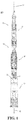
- the drilling system 200 can comprise a head assembly 10, such as, for example and without limitation, the head assembly depicted in Figures 1-3 .
- the head assembly 10 can be any conventionally known head assembly.
- the disclosed overshot assembly 30 can be configured for engagement with known head assemblies following removal of the spearhead assemblies conventionally associated with such head assemblies.
- the overshot assembly 30 can be configured for engagement with one or more receptacles matingly received within the head assembly 10.
- the one or more receptacles can similarly be configured for engagement with at least a portion of the overshot assembly 30.
- the head assembly 10 can have a longitudinal axis 12, an outer surface 14, an inner surface 16, and a proximal end 18.
- the inner surface 16 of the head assembly 10 can define a central bore 20 of the head assembly.
- the proximal end 18 of the head assembly 10 can define an opening 22 in operative communication with the central bore 20.
- the inner surface 16 of the head assembly 10 can define an inner diameter 24 of the head assembly.
- the head assembly 10 can comprise a retracting case 26 having an inner surface (corresponding to inner surface 16 of the head assembly) that is configured for engagement with a portion of the overshot 30.
- the inner surface 16 of the retracting case 26 optionally can define at least one groove 28 extending radially outwardly relative to the longitudinal axis 12 of the head assembly 10. It is further contemplated that the at least one groove 28 can comprise a plurality of grooves. In exemplary aspects, the at least one groove 28 can be spaced from the opening 22 of the proximal end 18 of the head assembly 10 relative to the longitudinal axis 12 of the head assembly. It is contemplated that the retracting case 26 can be an existing retracting case (as is currently known in the art) that is modified to have at least one groove 28 as described herein.
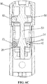
- the overshot 30 can have an elongate body 32.
- the elongate body 32 of the overshot 30 can comprise a proximal portion 34 having a longitudinal axis 35 and a distal portion 36 having a longitudinal axis 37.
- the proximal portion 34 of the elongate body 32 can comprise one or more conventional overshot components, including, for example and without limitation, a swivel element 33 and a conventional porting and valve configuration. At least a portion of the proximal portion 34 of the elongate body 32, such as, for example and without limitation, the swivel element 33, can be configured for secure engagement and/or coupling with a wireline cable 150 using known mechanisms.
- the swivel element 33 can comprise an eye bolt having a curved surface configured to matingly receive and engage a loop of the wireline cable 150.
- the proximal portion 34 of the elongate body 32 can further comprise a grease-lubricated thrust roller bearing configured to permit the eye bolt to swivel in response to excessive twisting in the wireline cable 150 that must be relieved in order to avoid damage to the wireline cable.
- the distal portion 36 of the elongate body 32 of the overshot 30 can be configured for receipt within the central bore 20 of the head assembly 10.
- the distal portion 36 of the elongate body 32 can have a wall 38 and an outer surface 40. It is contemplated that the wall 38 of the distal portion 36 of the elongate body 32 can define a central bore 42 of the elongate body.
- the wall 38 of the distal portion 36 of the elongate body 32 can define at least one proximal radial opening 44 extending from the outer surface 40 to the central bore 42 of the elongate body. It is further contemplated that the wall 38 of the distal portion 36 of the elongate body 32 can define at least one distal radial opening 46 extending from the outer surface 40 to the central bore 42 of the elongate body.
- the overshot 30 can comprise a driving member 50 positioned at least partially within the central bore 42 of the elongate body 32.
- the driving member 50 can have a longitudinal axis 52.
- the driving member 50 can comprise a wedge portion 54 defining at least one driving surface 56.
- each driving surface 56 of the at least one driving surface of the wedge portion 54 can be tapered relative to the longitudinal axis 52 of the driving member 50.
- each driving surface 56 can be tapered in a proximal direction toward the proximal portion 34.
- each driving surface 56 can be radially inwardly tapered relative to the longitudinal axis 52 of the driving member 50.
- each driving surface 56 can be radially inwardly tapered moving in a distal direction away from proximal portion 34.
- the driving member 50 can comprise a wedge portion 58 spaced from the wedge portion 54 relative to the longitudinal axis 52 of the driving member.
- the wedge portion 58 can define at least one driving surface 60, with each driving surface of the at least one driving surface being tapered relative to the longitudinal axis 52 of the driving member 50.
- each driving surface 60 can be radially inwardly tapered moving in a proximal direction toward proximal portion 34. That is, moving toward the proximal portion 34 of the overshot 30, it is contemplated that each driving surface 60 can be radially inwardly tapered relative to the longitudinal axis 52 of the driving member 50. However, in other optional aspects, it is contemplated that each driving surface 60 can be radially inwardly tapered moving in a distal direction away from proximal portion 34.
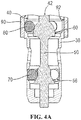
- the distal portion 34 of the overshot 30 can comprise at least one latch member 70 configured for movement about and between a latched position and a retracted position.
- the at least one latch member 70 can be configured for receipt within the at least one distal radial opening 46 of the elongate body 32. It is contemplated that each latch member 70 of the at least one latch member can be positioned in engagement with a corresponding driving surface 56 of the wedge portion 54 of the driving member 50. It is contemplated that each latch member 70 of the at least one latch member can be at least one of a ball, a roller, a cylinder, a cam-shaped element, and the like.
- the at least one driving surface 56 of the wedge portion 54 of the driving member can be configured to wedge the at least one latch member 70 between the inner surface of the head assembly 10 and the at least one driving surface 56 such that the overshot 30 contacts the inner surface 16 of the head assembly.
- the inner surface 16 of the head assembly 10 can be configured for secure engagement with the at least one latch member 70 of the overshot 30 when the at least one latch member is positioned in the latched position.
- the head assembly can be operatively coupled to the overshot such that movement of the overshot results in a corresponding movement of the head assembly.
- movement of the overshot 30 in one or more directions sufficient to exit a drilling formation can cause movement of the head assembly in the same directions such that the overshot and the head assembly can be removed from the drilling formation.
- the at least one latch member 70 of the overshot 30 can securely engage the inner surface 16 of the head assembly 10 such that the elongate body 32 cannot rotate relative to the head assembly.
- the at least one latch member 70 of the overshot when the at least one latch member 70 of the overshot is positioned in the retracted position, it is contemplated that the at least one latch member can define an outer diameter 72 of the distal portion 36 of the overshot 30 that is less than the inner diameter 24 of the head assembly 10. In further aspects, it is contemplated that the at least one latch member 70 can be biased toward the latched position. In exemplary aspects, the at least one latch member 70 can be spring-loaded toward the latched position. In these aspects, it is contemplated that the driving member can be spring-loaded toward an axial position in which the at least one latch member is urged toward the latched position (by wedge portion 54).
- the inner surface 16 of the retracting case 26 and/or the proximal end 18 of the head assembly can be configured to force the at least one latch member 70 into the retracted position (from the latched position).
- the at least one groove 28 can be configured to securely receive the at least one latch member 70 of the overshot 30 when the at least one latch member is positioned in the latched position.
- proximal end 18 of the head assembly 10 can be configured to abut a portion of the overshot 30 when the at least one latch member 70 is received within the at least one groove 28 of the retracting case 26.
- the at least one latch member 70 can be retracted relative to the inner surface 16 of the head assembly 10 such that the at least one latch member 70 disengages the inner surface of the head assembly.
- the overshot 30 can further comprise at least one locking member 80 configured for receipt within the at least one proximal radial opening 44 of the elongate body 32.
- each locking member 80 of the at least one locking member can be positioned in engagement with a corresponding driving surface 60 of wedge portion 58.
- the wedge portion 58 can be spaced from the wedge portion 54 relative to the longitudinal axis 52 of the driving member such that wedge portion 58 is positioned external to the head assembly 10 when the at least one latch member 70 is engaged with the inner surface 16 of the head assembly.
- each locking member 80 of the at least one locking member can be at least one of a ball, a roller, a cylinder, a cam-shaped element, and the like.
- the overshot 30 can comprise a locking sleeve 90 having an inner surface 92 configured for engagement with the outer surface 40 of the distal portion 36 of the elongate body 32.
- the locking sleeve 90 can be configured for rotational movement relative to the outer surface 40 of the elongate body 32 about and between a locked position and an unlocked position.
- the at least one driving surface 60 of wedge portion 58 can be configured to wedge the at least one locking member 80 between the inner surface 92 of the locking sleeve 90 and the at least one driving surface 60 of wedge portion 58 such that the elongate body 32 is prevented from rotating relative to the locking sleeve 90.
- the elongate body 32 can be configured for rotation relative to the locking sleeve.
- the wedge portions 54, 58 and the latching and locking members 70, 80 can be configured and positioned such that when the wedge portion 54 effects positioning of the latching elements 70 in the latched position, the wedge portion 58 can effect positioning of the locking elements 80 in the locked position.
- the wedge portions 54, 58 and the latching and locking elements 70, 80 can be configured and positioned such that when the wedge portion 54 is advanced longitudinally such that the latching elements return to the retracted position, the wedge portion 58 will also be advanced longitudinally, and the locking elements 80 will be returned to the retracted position.
- the latching elements 70 can be sized to protrude beyond the elongate body 32 and securely engage the inner surface 16 of the head assembly 10 while maintaining secure engagement with the elongate body.
- the latching elements upon engagement between the latching elements 70 and the inner surface 16 of the head assembly 10, can be configured to support loads applied by the overshot assembly 30.
- each wedge portion 54, 58 can be sized and shaped to accommodate movement of the latching and locking elements 70, 80 as described herein.
- each wedge portion 54, 58 can have outer surfaces that define an inward taper relative to the longitudinal axis 12 of the head assembly 10 as further described herein.
- the wedge portions 54, 58 can optionally have a substantially circular cross-sectional profile relative to the longitudinal axis 12 of the head assembly. It is further contemplated that the wedge portions can have shape substantially corresponding to a tapered cone.
- the tapered cone can have a varying tapered profile relative to the longitudinal axis 52 of the driving member 50.
- the driving member 50 can comprise an elongate driving member 50 defining a substantially cylindrical outer surface 51.
- the wedge portions 54, 58 of the driving member 50 can correspond to respective portions of the outer surface 51 of the elongate driving member 50.
- the driving surfaces 56, 60 defined by each wedge portion can correspond to grooves having an inwardly tapered profile relative to the longitudinal axis 52 of the driving member 50.
- each latching or locking member 70, 80 can be positioned within a respective groove of the wedge portions 54, 58 and be configured for movement within the groove during operation of the head assembly 10 as disclosed herein.
- the head assembly 10 can comprise a release mechanism operatively that permits release of a core barrel in the event the core barrel becomes stuck and/or jammed during drilling operations.
- the release mechanism can comprise a set of engagement members 140 operatively coupled to a distal portion 142 of the drive member 50 (for example, the portion of the drive member 50 most proximate a pivot joint element as further disclosed herein) and axially spaced from the latching and locking members 70, 80 relative to the longitudinal axis 52 of the drive member.
- the engagement members 140 can be configured for movement between a retracted position and a deployed position.
- the engagement members can comprise at least one of a ball, a roller, a cam-shaped element, and the like.
- the distal portion 142 of the drive member 50 can define a plurality of driving surfaces 144 configured for engagement with the engagement members 140.
- the driving surfaces 144 can be radially tapered moving relative to the longitudinal axis 52 of the driving member 50 such that axial movement of the driving member 50 can effect radial movement of the engagement members 140 between the retracted position and the deployed position.
- the driving surfaces 144 can be radially tapered in either direction relative to the longitudinal axis 52 of the driving member 50, depending upon the particular coupling arrangement (pinned, slotted, etc.) of the various components of the drilling system 200.
- the driving surfaces 144 can optionally be radially inwardly tapered moving toward the proximal portion 34 of the elongate body 32 relative to the longitudinal axis 52 of the driving member 50.
- the driving surfaces 144 can optionally be radially inwardly tapered moving away from the proximal portion 34 of the elongate body 32 relative to the longitudinal axis 52 of the driving member 50.
- the release mechanism can further comprise a release sleeve 146 defining a longitudinal slot 148.
- a portion of the wireline cable can be passed through the slot 148 of the release sleeve 146 such that the release sleeve substantially circumferentially surrounds the wireline cable. From this position, it is contemplated that the release sleeve 146 can be axially advanced toward the plurality of engagement members 140 until the sleeve lands on the outermost edges of the engagement members (with the engagement members positioned in the deployed position).
- the release sleeve can continue its axial movement relative to the longitudinal axis 52 of the drive member 50 (and away from the proximal portion 34 of the elongate body 32) until the release sleeve effects inward radial movement of the engagement elements 140 toward their retracted position and passes over the engagement elements.
- the overshot 30 when the overshot 30 is fully seated within a core barrel assembly as disclosed herein, the overshot can be axially advanced such that the latching and/or locking members 70, 80 are positioned in their retracted (un-latched and/or un-locked) positions.
- the term "fully seated” refers to a position in which there is substantially no wireline cable retraction tension and the overshot 30 is seated by gravity alone or by pump-in fluid pressure alone, thereby permitting the latch members 70 to be driven into their retracted/un-latched position.
- the overshot 30 is lifted slightly, and the latch members 70 are substantially adjacent to the latch groove in the retracting case, it is contemplated that the latch members can be returned by a spring load into their default deployed/latched position.
- the engagement members 140 can be operatively coupled to the latching and/or locking members 70, 80 through the driving member 50 such that the engagement members are positioned in a deployed position (for example, a radially extended position relative to the longitudinal axis 52 of the drive member 50) when the latching and/or locking members 70, 80 are positioned in a latched or locked position. It is further contemplated that the engagement members 140 can be operatively coupled to the latching and/or locking members 70, 80 such that, upon retraction of the engagement members, the latching and/or locking members 70, 80 are likewise radially retracted toward their respective retracted positions.
- retraction of the engagement members 140, latching members 70, and/or locking members 80 can be configured to permit release of a core barrel. It is further contemplated that, after the release sleeve 146 is passed over the engagement members 140 as disclosed herein, the release sleeve can remain positioned such that the engagement members 140 are incapable of outward radial movement toward the deployed position while the overshot 30 is lifted out of the core barrel assembly.
- the inner surface 92 of the locking sleeve 90 can define at least one groove 94 configured to receive at least a portion of a respective locking member 80 when the locking sleeve 90 is in the locked position. It is contemplated that the inner surface 92 of the locking sleeve 90 can further comprise at least one camming surface 96 configured for engagement with a respective locking member 80 during rotation (twisting) of the locking sleeve 90 such that the locking members of the at least one locking member are driven into the grooves 94 due to the biasing force of the driving member 50.
- the at least one camming surface 96 can be configured to provide bi-directional camming action; however, it is contemplated that uni-directional camming surfaces can also be used.
- the locking sleeve 90 can permit one-handed manual locking of the locking sleeve relative to the elongate body 32 and wedge portion 58. It is further contemplated that such one-handed manual locking can be used to position the at least one locking member 80 in the locked position and to position the at least one latch member in the latched position prior to insertion of the overshot assembly 30 into a drill hole.
- the twisting action of the locking sleeve 90 can be isolated from the axial forces experienced during tripping and/or external handling of the overshot assembly 30 (and head assembly 10).
- the latching members 70 and/or locking members 80 can protrude only a limited distance from the elongate body 32.
- the latching members, locking members, the elongate body 32, and/or the head assembly 10 can comprise corrosion and/or wear-resistant materials and/or be treated with corrosion and/or wear-resistant coatings or treatments.
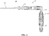
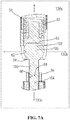
- the overshot 30 can further comprise a pivot joint element 100 positioned between and coupled to the proximal portion 34 and the distal portion 36 of the overshot.
- the distal portion 36 of the overshot 30 can be configured for pivotal movement in at least two planes relative to the proximal portion 34 of the overshot.
- the distal portion 36 of the overshot 30 can be configured for pivotal movement in three perpendicular planes relative to the proximal portion 34 of the overshot.
- the proximal portion 34 of the overshot 30 can have an inner surface 62 that defines a chamber 64.
- the distal portion 36 of the overshot 30 can have an inner surface 66 that defines a central bore 68.
- the pivot joint element 100 can further comprise a first end portion 102 configured for receipt within the chamber 64 of the proximal portion 34 of the overshot 30.
- the pivot joint element 100 can further comprise a second end portion 104 configured for secure attachment to the distal portion 36 of the overshot 30 upon receipt of the second end portion within the central bore 68 of the distal portion 36 of the overshot.
- the proximal portion 34 of the overshot 30 can comprise an engagement surface 63 positioned in communication with the chamber 64 of the proximal portion and oriented substantially perpendicularly relative to the longitudinal axis 35 of the proximal portion of the overshot.
- the engagement surface 63 can be defined by a plunger positioned in communication with the chamber 64.
- the plunger (and the engagement surface 63) can comprise bearing and wear-resistant materials, such as for example and without limitation, lubricated nylon, brass, and the like. It is further contemplated that the plunger (and the engagement surface 63) can be treated with a surface coating or treatment that is configured to promote easy relative movement and wear resistance.
- the first end portion 102 of the pivot joint element 100 can comprise a ball joint 106 having a substantially flat end surface 108.
- the pivot joint element 100 Upon positioning of the pivot joint element 100 such that the end surface 108 of the first end portion 102 is substantially flush with the engagement surface 63 of the proximal portion 34 of the overshot 30, it is contemplated that the longitudinal axes 35, 37 of the proximal and distal portions 34, 36 of the overshot 30 can be substantially axially aligned.
- the pivot joint element 100 can be configured to pivot in three perpendicular planes 130a, 130b, 130c relative to the proximal portion 34 of the overshot 30 such that the longitudinal axis 37 of the distal portion 36 of the overshot is positioned at an orientation angle 69 relative to the longitudinal axis 35 of the proximal portion 34 of the overshot.
- pivoting of the distal portion 36 of the overshot 30 can effect movement of the at least one latch element 70 (and the at least one locking element 80) from the latched position to the retracted position.
- the pivot joint element 100 can be configured to pivot in a first plane 130a relative to the proximal portion 34 of the overshot 30 such that the longitudinal axis 37 of the distal portion 36 of the overshot is substantially perpendicular to the longitudinal axis 35 of the proximal portion of the overshot.
- the orientation angle 69 of the longitudinal axis 37 of the distal portion 36 of the overshot 30 can range from about 0 degrees to about 90 degrees within the first plane 130a.
- the inner surface 62 of the proximal portion 34 of the overshot 30 can define a slot 65 configured to receive the pivot joint element 100 when the longitudinal axis 37 of the distal portion 36 of the overshot is positioned substantially perpendicularly relative to the longitudinal axis 35 of the proximal portion of the overshot. It is contemplated that the inner surface 62 of the proximal portion 34 of the overshot and the slot 65 can be positioned and shaped such that the inner surface 62 and the slot cooperate to restrict rotation of the distal portion 36 within the first plane 130a beyond a selected angle, such as, for example and without limitation, 90 degrees.
- a rounded portion of the ball joint 106 abuts a portion of the engagement surface 63 while the inner surface 62 engages a portion of the end surface 108 of the ball joint and an intermediate portion of the pivot joint (positioned distal to the ball joint) is engaged within the slot 65.
- the chamber 64 and the slot 65 can be sized and shaped to conform to the cross-sectional shape of the shaft portion of pivot joint element 100.
- the longitudinal axis 37 of the distal portion 36 of the overshot 30 can have an orientation angle 69 within each respective plane 130.
- the orientation angle 69 of the longitudinal axis 37 of the distal portion 36 of the overshot 30 can range from about 0 degrees to about 45 degrees within the second and third planes 130b, 130c.
- the inner surface 62 of the proximal portion 34 of the overshot and the engagement surface 63 can be positioned and shaped such that the inner surface 62 and the engagement surface cooperate to restrict rotation of the distal portion 36 within the second and third planes 130b, 130c beyond a selected angle, such as, for example and without limitation, 45 degrees.
- an edge portion of the end surface 108 of the ball joint 106 can engage a portion of the engagement surface 63 while the inner surface 62 engages at least one of: (a) a portion of the end surface 108 of the ball joint; (b) an intermediate portion of the pivot joint element 100 (positioned distal to the ball joint); and (c) a rounded portion of the ball joint.
- the engagement surface 63 can be defined by an elongate element that is spring-loaded by a spring 67.
- the spring 67 can be configured to bias the engagement surface 63 toward the chamber 64. It is further contemplated that the engagement surface 63 can be configured for axial translation relative to the longitudinal axis 35 of the proximal portion 34 of the overshot 30 upon application of a force sufficient to overcome the biasing force applied by the spring 67.
- the ball joint 106 in order to accomplish rotation of the distal portion 36 of the overshot 30 within the first plane 130a relative to the proximal portion 34 of the overshot, it is contemplated that the ball joint 106 must first apply an axial force to the engagement surface 63 such that the engagement surface translates a sufficient distance to permit rotation of the ball joint 106 within the chamber 64.
- the disclosed overshot assembly 30 and head assembly 10 can comprise more robust and reliable materials than conventional overshot systems.
- the investment castings and elongated geometries conventionally used in the components of overshot systems are associated with large dimensional variance, rough surfaces, mechanical property variance, material flaws, inclusion of foreign materials, and heat treatment limitations.
- the disclosed overshot assembly 30 and head assembly 10 can comprise machined and/or formed materials having reduced dimensional variance, thereby permitting tighter fits (due to more accurate production mechanisms) and a greater range of material properties and surface treatments.
- the latch members 70 and/or locking members 80 can comprise bearing grade hardened stainless steel rollers as are known in the art.
- the disclosed drilling system 200 provides a more compact design with a smaller number of parts, thereby ensuring improved reliability.
- the disclosed pivot joint element 100 can permit the overshot 30 to function at a wide range of angles and orientations, thereby eliminating the limitations of conventional spearhead pivot assemblies. More particularly, it is contemplated that the disclosed pivot joint element 100, which permits initial pivoting in 45 degrees in all orientations, eliminates the conventional requirement that the plane in which the overshot 30 pivots correspond to the axial orientation of the overshot. As described herein, only when an operator decides to pivot beyond 45 degrees (to 90 degrees) does the pivoting action need to complement the orientation of the overshot 30. The disclosed pivot joint element 100 therefore reduces the risk of overloading, which often occurred in conventional spearhead pivots when operators failed to orient their initial pivoting action with the spearhead.
Landscapes
- Life Sciences & Earth Sciences (AREA)
- Geology (AREA)
- Mining & Mineral Resources (AREA)
- Engineering & Computer Science (AREA)
- General Life Sciences & Earth Sciences (AREA)
- Fluid Mechanics (AREA)
- Marine Sciences & Fisheries (AREA)
- Environmental & Geological Engineering (AREA)
- Physics & Mathematics (AREA)
- Geochemistry & Mineralogy (AREA)
- Surgical Instruments (AREA)
- Multi-Conductor Connections (AREA)
- Installation Of Indoor Wiring (AREA)
- Motorcycle And Bicycle Frame (AREA)
- Earth Drilling (AREA)
Claims (13)
- Ein Überschuss (30), der Folgendes umfasst:einen proximalen Abschnitt (34), der zum Koppeln an eine Drahtleitung (150) eines Bohrsystems (200) konfiguriert ist, wobei der proximale Abschnitt des Überschusses eine Längsachse (35) und eine Innenfläche (62) aufweist, die eine Kammer (64) definieren, wobei der proximale Abschnitt eine Eingriffsfläche (63) umfasst, die in Verbindung mit der Kammer des proximalen Abschnitts positioniert und im Wesentlichen senkrecht zur Längsachse des proximalen Abschnitts ausgerichtet ist;einen distalen Abschnitt (36), der so konfiguriert ist, dass er mit einer Kopfanordnung (10) des Bohrsystems gekoppelt werden kann, wobei der distale Abschnitt des Überschusses eine Längsachse (37) und eine Innenfläche (66) aufweist, die eine zentrale Bohrung (68) definieren, undein Drehgelenkelement (100), das zwischen dem proximalen Abschnitt und dem distalen Abschnitt des Überschusses positioniert und mit diesem gekoppelt ist, wobei das Drehgelenkelement Folgendes umfasst:einen ersten Endabschnitt (102), der zur Aufnahme innerhalb der Kammer des proximalen Abschnitts des Überschusses konfiguriert ist, wobei der erste Endabschnitt ein Kugelgelenk (106) mit einer im Wesentlichen flachen Endfläche (108) umfasst, undeinen zweiten Endabschnitt (104), der zur sicheren Befestigung am distalen Abschnitt des Überschusses beim Empfang des zweiten Endabschnitts innerhalb der zentralen Bohrung des distalen Abschnitts des Überschusses konfiguriert ist,wobei bei der Positionierung des Drehgelenkelements, so dass die Endfläche des ersten Endabschnitts im Wesentlichen bündig mit der Eingriffsfläche des proximalen Abschnitts des Überschusses ist, die Längsachsen des proximalen und des distalen Abschnitts des Überschusses im Wesentlichen axial ausgerichtet sind,wobei der distale Teil des Überschusses für eine Schwenkbewegung in mindestens zwei Ebenen relativ zum proximalen Teil des Überschusses konfiguriert ist.
- Der Überschuss nach Anspruch 1, wobei das Drehgelenkelement für eine Drehbewegung in einer ersten Ebene (130a) relativ zum proximalen Abschnitt des Überschusses konfiguriert ist, so dass die Längsachse des distalen Abschnitts des Überschusses im Wesentlichen senkrecht zur Längsachse des proximalen Teils des Überschusses ist.
- Der Überschuss nach Anspruch 1, wobei das Drehgelenkelement für eine Drehbewegung in drei senkrechten Ebenen (130a, 130b, 130c) relativ zum proximalen Teil des Überschusses konfiguriert ist, so dass die Längsachse des distalen Abschnitts des Überschusses in einem Orientierungswinkel (69) relativ zur Längsachse des proximalen Abschnitts des Überschusses positioniert ist, wobei der Orientierungswinkel im Bereich von ungefähr 0 Grad bis ungefähr 45 Grad liegt.
- Der Überschuss nach Anspruch 1, wobei der distale Teil des Überschusses Folgendes umfasst:einen länglichen Körper (32) mit einer Wand (38) und einer Außenfläche (40), wobei die Wand des länglichen Körpers eine zentrale Bohrung (42) des länglichen Körpers und mindestens eine distale radiale Öffnung (46) definiert, die sich von der Außenfläche zur zentralen Bohrung des länglichen Körpers hin erstreckt;ein Antriebselement (50), das zumindest teilweise innerhalb der zentralen Bohrung des länglichen Körpers positioniert ist, wobei das Antriebselement eine Längsachse (52) und einen ersten Keilabschnitt (54) aufweist, wobei der erste Keilabschnitt mindestens eine Antriebsfläche (56) definiert, wobei jede Antriebsfläche der mindestens einen Antriebsfläche des ersten Keilabschnitts relativ zur Längsachse des Antriebselements verjüngt ist, undmindestens ein Verriegelungselement (70), das zur Aufnahme innerhalb der mindestens einen distalen radialen Öffnung des länglichen Körpers konfiguriert ist, wobei jedes Verriegelungselement des mindestens einen Verriegelungselements in Eingriff mit einer entsprechenden Antriebsfläche des ersten Keilabschnitts des Antriebselements steht,wobei bei Bewegung des Antriebselements in einer ersten Richtung, die im Wesentlichen parallel zur Längsachse des Antriebselements ist, die mindestens eine Antriebsfläche des Antriebselements so konfiguriert ist, dass sie das mindestens eine Verriegelungselement zwischen einer Innenfläche (16) der Kopfanordnung und der mindestens einen Antriebsfläche einklemmt, so dass der Überschuss sicher in die Innenfläche der Kopfanordnung eingreift.
- Der Überschuss nach Anspruch 2, wobei die Innenfläche des proximalen Abschnitts des Überschusses einen Schlitz (65) definiert, der so konfiguriert ist, dass er das Drehgelenkelement aufnimmt, wenn die Längsachse des distalen Abschnitts des Überschusses im Wesentlichen senkrecht zur Längsachse des proximalen Teils des Überschusses positioniert ist.
- Der Überschuss nach Anspruch 4, wobei das mindestens eine Verriegelungselement für eine Bewegung um und zwischen einer verriegelten Position und einer zurückgezogenen Position konfiguriert ist.
- Ein Bohrsystem zur Verwendung in einer Bohrformation, das Folgendes umfasst:eine Kopfanordnung mit einer Längsachse, einer Außenfläche, einer Innenfläche und einem proximalen Ende, wobei die Innenfläche der Kopfanordnung eine zentrale Bohrung definiert, wobei das proximale Ende der Kopfanordnung eine Öffnung in operativer Verbindung mit der zentralen Bohrung definiert, undein Überschuss wie in Anspruch 6 angegeben,wobei die Innenfläche der Kopfanordnung für einen sicheren Eingriff mit dem mindestens einen Verriegelungselement des Überschusses konfiguriert ist, wenn sich das mindestens eine Verriegelungselement in der Verriegelungsposition befindet, undwobei bei einem sicheren Eingriff zwischen dem mindestens einen Verriegelungselement des Überschusses und der Innenfläche der Kopfanordnung die Kopfanordnung operativ mit dem Überschuss gekoppelt ist, so dass eine Bewegung des Überschusses zu einer entsprechenden Bewegung der Kopfanordnung führt.
- Das Bohrsystem nach Anspruch 7, wobei bei Bewegung des Antriebselements in einer der ersten Richtung entgegengesetzten zweiten Richtung und im wesentlichen parallel zur Längsachse des Antriebselements das mindestens eine Verriegelungselement relativ zur Innenfläche der Kopfbaugruppe zurückgezogen wird.
- Das Bohrsystem nach Anspruch 8, wobei das Antriebselement einen zweiten Keilabschnitt aufweist, der vom ersten Keilabschnitt relativ zur Längsachse des Antriebselements beabstandet ist, so dass der zweite Keilabschnitt außerhalb der Kopfanordnung positioniert ist, wenn das mindestens eine Verriegelungselement mit der Innenfläche der Kopfanordnung in Eingriff ist, wobei der zweite Keilabschnitt mindestens eine Antriebsfläche definiert, wobei jede Antriebsfläche der mindestens einen Antriebsfläche des zweiten Keilabschnitts relativ zur Längsachse des Antriebselements verjüngt ist.
- Das Bohrsystem nach Anspruch 7, wobei das Drehgelenkelement für eine Drehbewegung in einer ersten Ebene relativ zum proximalen Abschnitt des Überschusses konfiguriert ist, so dass die Längsachse des distalen Abschnitts des Überschusses im Wesentlichen senkrecht zur Längsachse des proximalen Teils des Überschusses ist.
- Das Bohrsystem nach Anspruch 7 oder Anspruch 10, wobei die Innenfläche der Kopfanordnung einen Innendurchmesser (24) der Kopfanordnung definiert und wobei, wenn sich das mindestens eine Verriegelungselement des Überschusses in der zurückgezogenen Position befindet, das mindestens eine Verriegelungselement einen Außendurchmesser (72) eines distalen Abschnitts des Überschusses definiert, der kleiner ist als der Innendurchmesser der Kopfanordnung.
- Das Bohrsystem nach Anspruch 11, wobei die Kopfanordnung ein Rückzugsgehäuse (26) mit einer Innenfläche (16) umfasst, die zum Eingriff mit dem mindestens einen Verriegelungselement des Überschusses konfiguriert ist, um das mindestens eine Verriegelungselement von der verriegelten Position in die zurückgezogene Position zu bewegen.
- Das Bohrsystem nach Anspruch 12, wobei das mindestens eine Verriegelungselement in Richtung der Verriegelungsposition vorgespannt ist.
Applications Claiming Priority (3)
| Application Number | Priority Date | Filing Date | Title |
|---|---|---|---|
| US201261745039P | 2012-12-21 | 2012-12-21 | |
| EP13863927.3A EP2935782A4 (de) | 2012-12-21 | 2013-12-20 | Overshot-anordnung und systeme und verfahren zur verwendung davon |
| PCT/US2013/076855 WO2014100559A1 (en) | 2012-12-21 | 2013-12-20 | Overshot assembly and systems and methods of using same |
Related Parent Applications (1)
| Application Number | Title | Priority Date | Filing Date |
|---|---|---|---|
| EP13863927.3A Division EP2935782A4 (de) | 2012-12-21 | 2013-12-20 | Overshot-anordnung und systeme und verfahren zur verwendung davon |
Publications (2)
| Publication Number | Publication Date |
|---|---|
| EP3385498A1 EP3385498A1 (de) | 2018-10-10 |
| EP3385498B1 true EP3385498B1 (de) | 2020-08-05 |
Family
ID=50973372
Family Applications (2)
| Application Number | Title | Priority Date | Filing Date |
|---|---|---|---|
| EP18175071.2A Active EP3385498B1 (de) | 2012-12-21 | 2013-12-20 | Overshot-anordnung und systeme und verfahren zur verwendung davon |
| EP13863927.3A Withdrawn EP2935782A4 (de) | 2012-12-21 | 2013-12-20 | Overshot-anordnung und systeme und verfahren zur verwendung davon |
Family Applications After (1)
| Application Number | Title | Priority Date | Filing Date |
|---|---|---|---|
| EP13863927.3A Withdrawn EP2935782A4 (de) | 2012-12-21 | 2013-12-20 | Overshot-anordnung und systeme und verfahren zur verwendung davon |
Country Status (10)
| Country | Link |
|---|---|
| US (1) | US9540897B2 (de) |
| EP (2) | EP3385498B1 (de) |
| CN (1) | CN104854307B (de) |
| AU (1) | AU2013361158B2 (de) |
| BR (1) | BR112015010464A2 (de) |
| CA (1) | CA2890851C (de) |
| CL (1) | CL2015001746A1 (de) |
| PE (1) | PE20151104A1 (de) |
| WO (1) | WO2014100559A1 (de) |
| ZA (1) | ZA201502648B (de) |
Families Citing this family (10)
| Publication number | Priority date | Publication date | Assignee | Title |
|---|---|---|---|---|
| US9546524B2 (en) | 2013-12-31 | 2017-01-17 | Longyear Tm, Inc. | Handling and recovery devices for tubular members and associated methods |
| AU2016308257B2 (en) * | 2015-08-18 | 2021-12-23 | Boart Longyear Manufacturing And Distribution Inc. | Overshot assembly and systems and methods of using same |
| US10053973B2 (en) * | 2015-09-30 | 2018-08-21 | Longyear Tm, Inc. | Braking devices for drilling operations, and systems and methods of using same |
| PE20181223A1 (es) | 2015-12-14 | 2018-07-30 | Bly Ip Inc | Sistema y metodos para liberar una parte de una sarta de perforacion de un cable de perforacion |
| USD866481S1 (en) * | 2016-07-08 | 2019-11-12 | Thomas DeCosta | Handle grip for cable positioning |
| CN106089112B (zh) * | 2016-08-04 | 2018-03-09 | 中国石油天然气股份有限公司 | 一种井下电缆盘绕对接装置及其安装方法以及应用 |
| CN106401519B (zh) * | 2016-10-21 | 2019-01-22 | 承德市开发区富泉石油机械有限公司 | 一种带压取出井内断裂电缆的装置及方法 |
| CA3053533A1 (en) | 2017-02-17 | 2018-08-23 | Bly Ip Inc. | Reverse-circulation drilling assemblies and methods of using same |
| CN111236872B (zh) * | 2020-01-17 | 2021-10-29 | 中煤科工集团西安研究院有限公司 | 一种定向绳索取芯钻具及其钻探方法 |
| AU2021106826A4 (en) * | 2020-09-30 | 2021-11-18 | Boart Longyear Manufacturing And Distribution Inc. | Overshot assembly |
Citations (1)
| Publication number | Priority date | Publication date | Assignee | Title |
|---|---|---|---|---|
| US3173719A (en) * | 1963-04-09 | 1965-03-16 | Ringler Maurycy | Device for gripping and retrieving pipes or rods from bore holes |
Family Cites Families (13)
| Publication number | Priority date | Publication date | Assignee | Title |
|---|---|---|---|---|
| US1908174A (en) * | 1931-10-20 | 1933-05-09 | Daniel J O'grady | Drill string coupling |
| US2179594A (en) * | 1938-06-09 | 1939-11-14 | Albert E Johnson | Well tool |
| US3186745A (en) * | 1961-03-21 | 1965-06-01 | Lyles Cecil Ray | Well tools |
| US4281725A (en) * | 1979-09-20 | 1981-08-04 | Longyear Company | Knuckle joint spearhead core drilling apparatus |
| US4591197A (en) * | 1983-09-27 | 1986-05-27 | Ava International Corp. | Wire line running and/or pulling tool |
| US6089335A (en) | 1998-12-16 | 2000-07-18 | Boart Longyear International Holdings, Inc. | Positive latch core barrel apparatus |
| US6250405B1 (en) * | 1999-01-06 | 2001-06-26 | Western Well Tool, Inc. | Drill pipe protector assembly |
| US7901309B2 (en) * | 2004-09-01 | 2011-03-08 | Litens Automotive Partnership | Tensioner for a timing chain |
| CN201107207Y (zh) * | 2007-11-15 | 2008-08-27 | 中国石化集团胜利石油管理局钻井工艺研究院 | 非干扰式深海水合物钻探取样装置 |
| US7921926B2 (en) * | 2008-05-16 | 2011-04-12 | Longyear Tm, Inc. | Jointed spearhead assembly |
| US8485280B2 (en) * | 2009-10-07 | 2013-07-16 | Longyear Tm, Inc. | Core drilling tools with retractably lockable driven latch mechanisms |
| US8794355B2 (en) * | 2009-10-07 | 2014-08-05 | Longyear Tm, Inc. | Driven latch mechanism |
| RU2439285C1 (ru) * | 2010-06-15 | 2012-01-10 | Открытое акционерное общество "Татнефть" имени В.Д. Шашина | Устройство для извлечения оборудования из бокового ствола многозабойной скважины |
-
2013
- 2013-12-20 BR BR112015010464A patent/BR112015010464A2/pt not_active IP Right Cessation
- 2013-12-20 EP EP18175071.2A patent/EP3385498B1/de active Active
- 2013-12-20 EP EP13863927.3A patent/EP2935782A4/de not_active Withdrawn
- 2013-12-20 US US14/135,965 patent/US9540897B2/en active Active
- 2013-12-20 PE PE2015001050A patent/PE20151104A1/es active IP Right Grant
- 2013-12-20 CA CA2890851A patent/CA2890851C/en active Active
- 2013-12-20 CN CN201380057024.4A patent/CN104854307B/zh not_active Expired - Fee Related
- 2013-12-20 WO PCT/US2013/076855 patent/WO2014100559A1/en not_active Ceased
- 2013-12-20 AU AU2013361158A patent/AU2013361158B2/en active Active
-
2015
- 2015-04-20 ZA ZA2015/02648A patent/ZA201502648B/en unknown
- 2015-06-18 CL CL2015001746A patent/CL2015001746A1/es unknown
Patent Citations (1)
| Publication number | Priority date | Publication date | Assignee | Title |
|---|---|---|---|---|
| US3173719A (en) * | 1963-04-09 | 1965-03-16 | Ringler Maurycy | Device for gripping and retrieving pipes or rods from bore holes |
Also Published As
| Publication number | Publication date |
|---|---|
| WO2014100559A1 (en) | 2014-06-26 |
| EP3385498A1 (de) | 2018-10-10 |
| US9540897B2 (en) | 2017-01-10 |
| AU2013361158B2 (en) | 2016-12-08 |
| CL2015001746A1 (es) | 2015-11-06 |
| ZA201502648B (en) | 2017-11-29 |
| CA2890851A1 (en) | 2014-06-26 |
| EP2935782A1 (de) | 2015-10-28 |
| CN104854307B (zh) | 2018-04-27 |
| CA2890851C (en) | 2017-11-07 |
| AU2013361158A1 (en) | 2015-05-07 |
| PE20151104A1 (es) | 2015-08-06 |
| EP2935782A4 (de) | 2017-06-21 |
| US20140174832A1 (en) | 2014-06-26 |
| BR112015010464A2 (pt) | 2017-07-11 |
| CN104854307A (zh) | 2015-08-19 |
Similar Documents
| Publication | Publication Date | Title |
|---|---|---|
| EP3385498B1 (de) | Overshot-anordnung und systeme und verfahren zur verwendung davon | |
| US11268340B2 (en) | Overshot assembly and systems and methods of using same | |
| EP3730733B1 (de) | Systeme und verfahren zur freisetzung eines teils eines bohrstrangs aus einem bohrkabel | |
| EP2274500B1 (de) | Anordnung aus verbundenen stosskeilen | |
| US10208541B2 (en) | Pullback system for drilling tool | |
| CA2934355C (en) | Locking nut with a directional coupling mechanism | |
| AU2021106826A4 (en) | Overshot assembly |
Legal Events
| Date | Code | Title | Description |
|---|---|---|---|
| PUAI | Public reference made under article 153(3) epc to a published international application that has entered the european phase |
Free format text: ORIGINAL CODE: 0009012 |
|
| STAA | Information on the status of an ep patent application or granted ep patent |
Free format text: STATUS: THE APPLICATION HAS BEEN PUBLISHED |
|
| AC | Divisional application: reference to earlier application |
Ref document number: 2935782 Country of ref document: EP Kind code of ref document: P |
|
| AK | Designated contracting states |
Kind code of ref document: A1 Designated state(s): AL AT BE BG CH CY CZ DE DK EE ES FI FR GB GR HR HU IE IS IT LI LT LU LV MC MK MT NL NO PL PT RO RS SE SI SK SM TR |
|
| STAA | Information on the status of an ep patent application or granted ep patent |
Free format text: STATUS: REQUEST FOR EXAMINATION WAS MADE |
|
| 17P | Request for examination filed |
Effective date: 20190409 |
|
| RBV | Designated contracting states (corrected) |
Designated state(s): AL AT BE BG CH CY CZ DE DK EE ES FI FR GB GR HR HU IE IS IT LI LT LU LV MC MK MT NL NO PL PT RO RS SE SI SK SM TR |
|
| STAA | Information on the status of an ep patent application or granted ep patent |
Free format text: STATUS: EXAMINATION IS IN PROGRESS |
|
| 17Q | First examination report despatched |
Effective date: 20190522 |
|
| GRAP | Despatch of communication of intention to grant a patent |
Free format text: ORIGINAL CODE: EPIDOSNIGR1 |
|
| STAA | Information on the status of an ep patent application or granted ep patent |
Free format text: STATUS: GRANT OF PATENT IS INTENDED |
|
| INTG | Intention to grant announced |
Effective date: 20200318 |
|
| GRAS | Grant fee paid |
Free format text: ORIGINAL CODE: EPIDOSNIGR3 |
|
| GRAA | (expected) grant |
Free format text: ORIGINAL CODE: 0009210 |
|
| STAA | Information on the status of an ep patent application or granted ep patent |
Free format text: STATUS: THE PATENT HAS BEEN GRANTED |
|
| AC | Divisional application: reference to earlier application |
Ref document number: 2935782 Country of ref document: EP Kind code of ref document: P |
|
| AK | Designated contracting states |
Kind code of ref document: B1 Designated state(s): AL AT BE BG CH CY CZ DE DK EE ES FI FR GB GR HR HU IE IS IT LI LT LU LV MC MK MT NL NO PL PT RO RS SE SI SK SM TR |
|
| REG | Reference to a national code |
Ref country code: GB Ref legal event code: FG4D |
|
| REG | Reference to a national code |
Ref country code: CH Ref legal event code: EP |
|
| REG | Reference to a national code |
Ref country code: AT Ref legal event code: REF Ref document number: 1298948 Country of ref document: AT Kind code of ref document: T Effective date: 20200815 |
|
| REG | Reference to a national code |
Ref country code: DE Ref legal event code: R096 Ref document number: 602013071481 Country of ref document: DE |
|
| REG | Reference to a national code |
Ref country code: IE Ref legal event code: FG4D |
|
| REG | Reference to a national code |
Ref country code: FI Ref legal event code: FGE |
|
| REG | Reference to a national code |
Ref country code: SE Ref legal event code: TRGR |
|
| REG | Reference to a national code |
Ref country code: LT Ref legal event code: MG4D |
|
| REG | Reference to a national code |
Ref country code: NL Ref legal event code: MP Effective date: 20200805 |
|
| REG | Reference to a national code |
Ref country code: AT Ref legal event code: MK05 Ref document number: 1298948 Country of ref document: AT Kind code of ref document: T Effective date: 20200805 |
|
| PG25 | Lapsed in a contracting state [announced via postgrant information from national office to epo] |
Ref country code: BG Free format text: LAPSE BECAUSE OF FAILURE TO SUBMIT A TRANSLATION OF THE DESCRIPTION OR TO PAY THE FEE WITHIN THE PRESCRIBED TIME-LIMIT Effective date: 20201105 Ref country code: ES Free format text: LAPSE BECAUSE OF FAILURE TO SUBMIT A TRANSLATION OF THE DESCRIPTION OR TO PAY THE FEE WITHIN THE PRESCRIBED TIME-LIMIT Effective date: 20200805 Ref country code: PT Free format text: LAPSE BECAUSE OF FAILURE TO SUBMIT A TRANSLATION OF THE DESCRIPTION OR TO PAY THE FEE WITHIN THE PRESCRIBED TIME-LIMIT Effective date: 20201207 Ref country code: GR Free format text: LAPSE BECAUSE OF FAILURE TO SUBMIT A TRANSLATION OF THE DESCRIPTION OR TO PAY THE FEE WITHIN THE PRESCRIBED TIME-LIMIT Effective date: 20201106 Ref country code: NO Free format text: LAPSE BECAUSE OF FAILURE TO SUBMIT A TRANSLATION OF THE DESCRIPTION OR TO PAY THE FEE WITHIN THE PRESCRIBED TIME-LIMIT Effective date: 20201105 Ref country code: LT Free format text: LAPSE BECAUSE OF FAILURE TO SUBMIT A TRANSLATION OF THE DESCRIPTION OR TO PAY THE FEE WITHIN THE PRESCRIBED TIME-LIMIT Effective date: 20200805 Ref country code: AT Free format text: LAPSE BECAUSE OF FAILURE TO SUBMIT A TRANSLATION OF THE DESCRIPTION OR TO PAY THE FEE WITHIN THE PRESCRIBED TIME-LIMIT Effective date: 20200805 Ref country code: HR Free format text: LAPSE BECAUSE OF FAILURE TO SUBMIT A TRANSLATION OF THE DESCRIPTION OR TO PAY THE FEE WITHIN THE PRESCRIBED TIME-LIMIT Effective date: 20200805 |
|
| PG25 | Lapsed in a contracting state [announced via postgrant information from national office to epo] |
Ref country code: IS Free format text: LAPSE BECAUSE OF FAILURE TO SUBMIT A TRANSLATION OF THE DESCRIPTION OR TO PAY THE FEE WITHIN THE PRESCRIBED TIME-LIMIT Effective date: 20201205 Ref country code: RS Free format text: LAPSE BECAUSE OF FAILURE TO SUBMIT A TRANSLATION OF THE DESCRIPTION OR TO PAY THE FEE WITHIN THE PRESCRIBED TIME-LIMIT Effective date: 20200805 Ref country code: PL Free format text: LAPSE BECAUSE OF FAILURE TO SUBMIT A TRANSLATION OF THE DESCRIPTION OR TO PAY THE FEE WITHIN THE PRESCRIBED TIME-LIMIT Effective date: 20200805 Ref country code: NL Free format text: LAPSE BECAUSE OF FAILURE TO SUBMIT A TRANSLATION OF THE DESCRIPTION OR TO PAY THE FEE WITHIN THE PRESCRIBED TIME-LIMIT Effective date: 20200805 Ref country code: LV Free format text: LAPSE BECAUSE OF FAILURE TO SUBMIT A TRANSLATION OF THE DESCRIPTION OR TO PAY THE FEE WITHIN THE PRESCRIBED TIME-LIMIT Effective date: 20200805 |
|
| PG25 | Lapsed in a contracting state [announced via postgrant information from national office to epo] |
Ref country code: DK Free format text: LAPSE BECAUSE OF FAILURE TO SUBMIT A TRANSLATION OF THE DESCRIPTION OR TO PAY THE FEE WITHIN THE PRESCRIBED TIME-LIMIT Effective date: 20200805 Ref country code: CZ Free format text: LAPSE BECAUSE OF FAILURE TO SUBMIT A TRANSLATION OF THE DESCRIPTION OR TO PAY THE FEE WITHIN THE PRESCRIBED TIME-LIMIT Effective date: 20200805 Ref country code: RO Free format text: LAPSE BECAUSE OF FAILURE TO SUBMIT A TRANSLATION OF THE DESCRIPTION OR TO PAY THE FEE WITHIN THE PRESCRIBED TIME-LIMIT Effective date: 20200805 Ref country code: EE Free format text: LAPSE BECAUSE OF FAILURE TO SUBMIT A TRANSLATION OF THE DESCRIPTION OR TO PAY THE FEE WITHIN THE PRESCRIBED TIME-LIMIT Effective date: 20200805 Ref country code: SM Free format text: LAPSE BECAUSE OF FAILURE TO SUBMIT A TRANSLATION OF THE DESCRIPTION OR TO PAY THE FEE WITHIN THE PRESCRIBED TIME-LIMIT Effective date: 20200805 |
|
| REG | Reference to a national code |
Ref country code: DE Ref legal event code: R097 Ref document number: 602013071481 Country of ref document: DE |
|
| PG25 | Lapsed in a contracting state [announced via postgrant information from national office to epo] |
Ref country code: AL Free format text: LAPSE BECAUSE OF FAILURE TO SUBMIT A TRANSLATION OF THE DESCRIPTION OR TO PAY THE FEE WITHIN THE PRESCRIBED TIME-LIMIT Effective date: 20200805 |
|
| PLBE | No opposition filed within time limit |
Free format text: ORIGINAL CODE: 0009261 |
|
| STAA | Information on the status of an ep patent application or granted ep patent |
Free format text: STATUS: NO OPPOSITION FILED WITHIN TIME LIMIT |
|
| PG25 | Lapsed in a contracting state [announced via postgrant information from national office to epo] |
Ref country code: SK Free format text: LAPSE BECAUSE OF FAILURE TO SUBMIT A TRANSLATION OF THE DESCRIPTION OR TO PAY THE FEE WITHIN THE PRESCRIBED TIME-LIMIT Effective date: 20200805 |
|
| REG | Reference to a national code |
Ref country code: DE Ref legal event code: R119 Ref document number: 602013071481 Country of ref document: DE |
|
| 26N | No opposition filed |
Effective date: 20210507 |
|
| PG25 | Lapsed in a contracting state [announced via postgrant information from national office to epo] |
Ref country code: IT Free format text: LAPSE BECAUSE OF FAILURE TO SUBMIT A TRANSLATION OF THE DESCRIPTION OR TO PAY THE FEE WITHIN THE PRESCRIBED TIME-LIMIT Effective date: 20200805 |
|
| REG | Reference to a national code |
Ref country code: CH Ref legal event code: PL |
|
| GBPC | Gb: european patent ceased through non-payment of renewal fee |
Effective date: 20201220 |
|
| PG25 | Lapsed in a contracting state [announced via postgrant information from national office to epo] |
Ref country code: SI Free format text: LAPSE BECAUSE OF FAILURE TO SUBMIT A TRANSLATION OF THE DESCRIPTION OR TO PAY THE FEE WITHIN THE PRESCRIBED TIME-LIMIT Effective date: 20200805 Ref country code: MC Free format text: LAPSE BECAUSE OF FAILURE TO SUBMIT A TRANSLATION OF THE DESCRIPTION OR TO PAY THE FEE WITHIN THE PRESCRIBED TIME-LIMIT Effective date: 20200805 |
|
| REG | Reference to a national code |
Ref country code: BE Ref legal event code: MM Effective date: 20201231 |
|
| PG25 | Lapsed in a contracting state [announced via postgrant information from national office to epo] |
Ref country code: IE Free format text: LAPSE BECAUSE OF NON-PAYMENT OF DUE FEES Effective date: 20201220 Ref country code: LU Free format text: LAPSE BECAUSE OF NON-PAYMENT OF DUE FEES Effective date: 20201220 |
|
| PG25 | Lapsed in a contracting state [announced via postgrant information from national office to epo] |
Ref country code: GB Free format text: LAPSE BECAUSE OF NON-PAYMENT OF DUE FEES Effective date: 20201220 Ref country code: LI Free format text: LAPSE BECAUSE OF NON-PAYMENT OF DUE FEES Effective date: 20201231 Ref country code: DE Free format text: LAPSE BECAUSE OF NON-PAYMENT OF DUE FEES Effective date: 20210701 Ref country code: CH Free format text: LAPSE BECAUSE OF NON-PAYMENT OF DUE FEES Effective date: 20201231 |
|
| PG25 | Lapsed in a contracting state [announced via postgrant information from national office to epo] |
Ref country code: IS Free format text: LAPSE BECAUSE OF FAILURE TO SUBMIT A TRANSLATION OF THE DESCRIPTION OR TO PAY THE FEE WITHIN THE PRESCRIBED TIME-LIMIT Effective date: 20201205 Ref country code: TR Free format text: LAPSE BECAUSE OF FAILURE TO SUBMIT A TRANSLATION OF THE DESCRIPTION OR TO PAY THE FEE WITHIN THE PRESCRIBED TIME-LIMIT Effective date: 20200805 Ref country code: MT Free format text: LAPSE BECAUSE OF FAILURE TO SUBMIT A TRANSLATION OF THE DESCRIPTION OR TO PAY THE FEE WITHIN THE PRESCRIBED TIME-LIMIT Effective date: 20200805 Ref country code: CY Free format text: LAPSE BECAUSE OF FAILURE TO SUBMIT A TRANSLATION OF THE DESCRIPTION OR TO PAY THE FEE WITHIN THE PRESCRIBED TIME-LIMIT Effective date: 20200805 |
|
| PG25 | Lapsed in a contracting state [announced via postgrant information from national office to epo] |
Ref country code: MK Free format text: LAPSE BECAUSE OF FAILURE TO SUBMIT A TRANSLATION OF THE DESCRIPTION OR TO PAY THE FEE WITHIN THE PRESCRIBED TIME-LIMIT Effective date: 20200805 |
|
| PG25 | Lapsed in a contracting state [announced via postgrant information from national office to epo] |
Ref country code: BE Free format text: LAPSE BECAUSE OF NON-PAYMENT OF DUE FEES Effective date: 20201231 |
|
| P01 | Opt-out of the competence of the unified patent court (upc) registered |
Effective date: 20230523 |
|
| PGFP | Annual fee paid to national office [announced via postgrant information from national office to epo] |
Ref country code: FI Payment date: 20251029 Year of fee payment: 13 |
|
| PGFP | Annual fee paid to national office [announced via postgrant information from national office to epo] |
Ref country code: FR Payment date: 20251013 Year of fee payment: 13 |
|
| PGFP | Annual fee paid to national office [announced via postgrant information from national office to epo] |
Ref country code: SE Payment date: 20251010 Year of fee payment: 13 |