EP3385605A1 - Kühlvorrichtung - Google Patents
Kühlvorrichtung Download PDFInfo
- Publication number
- EP3385605A1 EP3385605A1 EP17382186.9A EP17382186A EP3385605A1 EP 3385605 A1 EP3385605 A1 EP 3385605A1 EP 17382186 A EP17382186 A EP 17382186A EP 3385605 A1 EP3385605 A1 EP 3385605A1
- Authority
- EP
- European Patent Office
- Prior art keywords
- cooling device
- input
- output
- heater
- source point
- Prior art date
- Legal status (The legal status is an assumption and is not a legal conclusion. Google has not performed a legal analysis and makes no representation as to the accuracy of the status listed.)
- Withdrawn
Links
- 238000001816 cooling Methods 0.000 title claims abstract description 47
- 239000012080 ambient air Substances 0.000 claims abstract description 33
- 239000012530 fluid Substances 0.000 claims abstract description 22
- 230000007423 decrease Effects 0.000 claims description 22
- 230000003247 decreasing effect Effects 0.000 claims description 5
- 239000004065 semiconductor Substances 0.000 claims description 4
- 239000003570 air Substances 0.000 description 9
- 230000017525 heat dissipation Effects 0.000 description 4
- 239000000853 adhesive Substances 0.000 description 2
- 230000001070 adhesive effect Effects 0.000 description 2
- 230000003044 adaptive effect Effects 0.000 description 1
- 230000001419 dependent effect Effects 0.000 description 1
Images

Classifications
-
- F—MECHANICAL ENGINEERING; LIGHTING; HEATING; WEAPONS; BLASTING
- F21—LIGHTING
- F21S—NON-PORTABLE LIGHTING DEVICES; SYSTEMS THEREOF; VEHICLE LIGHTING DEVICES SPECIALLY ADAPTED FOR VEHICLE EXTERIORS
- F21S45/00—Arrangements within vehicle lighting devices specially adapted for vehicle exteriors, for purposes other than emission or distribution of light
- F21S45/40—Cooling of lighting devices
- F21S45/42—Forced cooling
- F21S45/43—Forced cooling using gas
-
- F—MECHANICAL ENGINEERING; LIGHTING; HEATING; WEAPONS; BLASTING
- F21—LIGHTING
- F21S—NON-PORTABLE LIGHTING DEVICES; SYSTEMS THEREOF; VEHICLE LIGHTING DEVICES SPECIALLY ADAPTED FOR VEHICLE EXTERIORS
- F21S41/00—Illuminating devices specially adapted for vehicle exteriors, e.g. headlamps
- F21S41/10—Illuminating devices specially adapted for vehicle exteriors, e.g. headlamps characterised by the light source
- F21S41/14—Illuminating devices specially adapted for vehicle exteriors, e.g. headlamps characterised by the light source characterised by the type of light source
- F21S41/141—Light emitting diodes [LED]
- F21S41/147—Light emitting diodes [LED] the main emission direction of the LED being angled to the optical axis of the illuminating device
Definitions
- This invention is related to the field of heat dissipation in automotive lighting devices.
- Light sources generate a big amount of heat which needs to be dissipated, so that the operation of said light sources is not jeopardized. This issue is even more important when light sources are light emitting diodes (LEDs), since temperature has a big impact on the operational properties of said light sources.
- LEDs light emitting diodes
- Heat sinks with heaters are known to solve this problem.
- a heat sink is located in thermal contact with the light source, and this heat sink is provided with heaters, which dissipate the heat coming from the heat sink, so that air surrounding the heater is heated and then wasted.
- the invention provides a solution for reusing the wasted air in order to optimise heat dissipation by means of a cooling device according to claim 1 and an automotive lighting device according to claim 10.
- Preferred embodiments of the invention are defined in dependent claims.
- the invention provides a cooling device for cooling a light source comprised in an automotive lighting device, the cooling device comprising
- such a cooling device uses ambient air which has been heated by the heater, and is otherwise wasted, in order to reduce the temperature of the light source.
- the cooling device further comprises a fan element arranged to force airflow from the input to the output.
- This fan element contributes to create the air flow between the input and the output, and is able to regulate the intensity of such an air flow.
- the output has a smaller surface than the input.
- This arrangement makes the air speed increase from the input to the output, provided air flow does not present major fluid irregularities, which is the case in the majority of the applications of this cooling device.
- the passageway comprises
- Cross section is reduced from the input to the output to contribute to the increase of air speed. It has been found that a first section with an increasing decrease rate and a second section with a decreasing decrease rate is optimal for this purpose.
- first section and the second section are two separate portions attachable to one another.
- these embodiments are able to adapt better to different heat sinks, since one of the portions may be the same for all different heat sinks and the other portion be adaptive to different heat sink designs.
- the heater comprises fins.
- Fins improve heat dissipation, so they are useful for transferring heat from the heat sink to ambient air.
- ambient air is not heated in a way that prevents it from being used for further cooling.
- the flow guide is attached or fitted into the heat sink.
- the flow guide may be attached to the heat sink, either by external elements, such as screws, rivets or an adhesive, or just by press fitting or snap fitting. This way of arranging the flow guide provide stability to the cooling device.
- the heat sink comprises a further source point intended to receive a light source, the heater being in thermal contact with the further source point and the cooling device comprises a further flow guide, the further flow guide comprising a further input, a further output and a further fluid passageway between the further input and the further output, the further input being in fluid contact with the heater and the further output being in fluid contact with the further source point so that, when the heated ambient air is generated by the heater, the heated ambient air is allowed to flow from the further input to the further output thereby evacuating heat, by thermal convection, from the further source point.
- the heat sink has two faces opposite to one another, and each source point is comprised in one of these faces.
- This embodiment is used in arrangements where two or more light sources are located on opposite faces of the heat sink.
- a second flow guide is installed in an analogue way as the first one, with its own input and output.
- both inputs are fed by the same ambient air and in other embodiments, although both inputs are in fluid contact, they are not in direct connection.
- the invention provides an automotive lighting device comprising
- the automotive lighting device further comprises a reflector, in such a way that the cooling device is partly located between the reflector and the light source.
- This automotive lighting device presents a better thermal behaviour, but without increasing substantially its size, since the flow guide just serves as a guide for ambient air, but without taking much more additional volume in the lighting device.
- the light source is a semiconductor light source, such as a light emitting diode (LED).
- LED light emitting diode
- FIG. 1 shows a cooling device 1' of an automotive lighting device according to the state of the art.
- This lighting device comprises a light source 5' and a heat sink 2' in thermal contact with the light source, the heat sink dissipating heat from the light source.
- This heat sink exchanges heat with ambient air by means of a heater 22', which is placed in one end of the heat sink 2'.
- a heater 22' By means of this heater 22', the heat received from the light source 5' is evacuated and increases the temperature of surrounding air.
- FIGS 2 and 3 show a cooling device 1 according to the invention, installed in a lighting device 10 comprising two semiconductor light sources 5, 105, such as LEDs or laser diodes.
- This lighting device 10 further comprises reflectors 6, 106, in such a way that the cooling device 1 is partly located between a reflector 6, 106 and the corresponding light source 5, 105.
- This cooling device 1 comprises
- the cooling device 1 also comprises a further flow guide 103, but it will be described below, since it is symmetric to the flow guide 3.
- the heated ambient air When the heated ambient air is generated by the heater, the heated ambient air is allowed to flow from the input 31 to the output 32 thereby evacuating heat, by thermal convection, from the source point 21.
- the output 32 has a smaller surface than the input 31.
- the passageway 30 comprises two separate portions 33, 34, in such a way that the cross section of the passageway 30 decreases in a different way in each of these portions 33, 34
- the passageway just comprises a single portion with two different sections.
- the heat sink 2 comprises two faces 24, 25, opposite to one another.
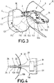
- Figure 2 shows the automotive lighting device 10 from the first face 24, and figure 3 shows the same lighting device 10 from the opposite face 25.
- a further source point 121 is seen in this opposite face 25, intended to receive a further light source 105.
- the further light source 105 has a corresponding further flow guide 103.
- the flow guides 3, 103 are substantially identical, but are placed in a symmetrical way with respect to the heat sink 2.
- the further flow guide 103 comprises a further input 131 where heated ambient air enters a further output 132 where this heated ambient air exits to dissipate heat from the further lighting source 105.
- the heater is in thermal contact with the further source point 121.
- the further flow guide 103 comprises a further input 131, a further output 132 and a further fluid passageway 130 between the further input 131 and the further output 132, the further input 131 being in fluid contact with the heater (not shown in this figure) and the further output 132 being in fluid contact with the further source point 121 so that, when the heated ambient air is generated by the heater, the heated ambient air is allowed to flow from the further input 131 to the further output 132 thereby evacuating heat, by thermal convection, from the further source point 121.
- the passageway 130 comprises two separate portions 133, 134, in such a way that the cross section of the passageway 130 decreases in a different way in each of these portions 133, 134
- the flow guides 3, 103 are attached or fitted into the heat sink 2.
- the flow guides 3, 103 are attached to the heat sink 2 by external elements, such as screws or rivets.
- An adhesive may also be used for this purpose.
- Another way of attaching these elements is just by press fitting or snap fitting. This makes easier to exchange different cooling devices between different types of heat sinks 2.
- Figure 4 shows a longitudinal cut section of this cooling device 1.
- this cut section it is observed how the heat comes from the light sources 5, 105, it is then transmitted by conduction by the heat sink 2 to the heater 22, which has fins for better heat dissipation.
- the fan element 4 reintroduce this ambient air into the passageways 30, 130 to reduce the temperature of the light sources 5, 105.
- the reason is that, although the ambient air has been heated by the heater, its temperature is still much lower than the temperature of the light sources 5, 105. As a consequence, this heated ambient air has still thermal properties to dissipate heat from the light sources 5, 105 by convection.
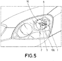
- FIG. 1 shows an automotive lighting device 10 comprising
- This automotive lighting device 10 benefits from the cooling device 1, so that the light source 5 comprised in it is cooled both by conduction, by means of the heat sink, and by convection, by means of the heated air flowing across the passageway of the flow guide.
- the light source 5 is a semiconductor light source, and in particular a LED source.
Landscapes
- Engineering & Computer Science (AREA)
- General Engineering & Computer Science (AREA)
- Arrangement Of Elements, Cooling, Sealing, Or The Like Of Lighting Devices (AREA)
- Non-Portable Lighting Devices Or Systems Thereof (AREA)
Priority Applications (1)
| Application Number | Priority Date | Filing Date | Title |
|---|---|---|---|
| EP17382186.9A EP3385605A1 (de) | 2017-04-06 | 2017-04-06 | Kühlvorrichtung |
Applications Claiming Priority (1)
| Application Number | Priority Date | Filing Date | Title |
|---|---|---|---|
| EP17382186.9A EP3385605A1 (de) | 2017-04-06 | 2017-04-06 | Kühlvorrichtung |
Publications (1)
| Publication Number | Publication Date |
|---|---|
| EP3385605A1 true EP3385605A1 (de) | 2018-10-10 |
Family
ID=58536923
Family Applications (1)
| Application Number | Title | Priority Date | Filing Date |
|---|---|---|---|
| EP17382186.9A Withdrawn EP3385605A1 (de) | 2017-04-06 | 2017-04-06 | Kühlvorrichtung |
Country Status (1)
| Country | Link |
|---|---|
| EP (1) | EP3385605A1 (de) |
Cited By (3)
| Publication number | Priority date | Publication date | Assignee | Title |
|---|---|---|---|---|
| FR3115585A1 (fr) * | 2020-10-23 | 2022-04-29 | Psa Automobiles Sa | Module lumineux avec systeme de dissipation thermique. |
| EP4194743A1 (de) * | 2021-12-10 | 2023-06-14 | Valeo Vision | Beleuchtungsvorrichtung für ein kraftfahrzeug |
| EP4563882A1 (de) * | 2023-11-30 | 2025-06-04 | Lumileds LLC | Retrofit led-lampe |
Citations (4)
| Publication number | Priority date | Publication date | Assignee | Title |
|---|---|---|---|---|
| US20070091632A1 (en) * | 2005-10-25 | 2007-04-26 | Visteon Global Technologies, Inc. | Convectively cooled headlamp assembly |
| EP3043107A1 (de) * | 2015-01-09 | 2016-07-13 | Valeo Vision | Optisches modul für kraftfahrzeugscheinwerfer |
| US20170038025A1 (en) * | 2015-08-04 | 2017-02-09 | Lg Innotek Co., Ltd. | Vehicular lamp |
| EP3147556A1 (de) * | 2015-09-24 | 2017-03-29 | Stanley Electric Co., Ltd. | Fahrzeugbeleuchtungsvorrichtung |
-
2017
- 2017-04-06 EP EP17382186.9A patent/EP3385605A1/de not_active Withdrawn
Patent Citations (4)
| Publication number | Priority date | Publication date | Assignee | Title |
|---|---|---|---|---|
| US20070091632A1 (en) * | 2005-10-25 | 2007-04-26 | Visteon Global Technologies, Inc. | Convectively cooled headlamp assembly |
| EP3043107A1 (de) * | 2015-01-09 | 2016-07-13 | Valeo Vision | Optisches modul für kraftfahrzeugscheinwerfer |
| US20170038025A1 (en) * | 2015-08-04 | 2017-02-09 | Lg Innotek Co., Ltd. | Vehicular lamp |
| EP3147556A1 (de) * | 2015-09-24 | 2017-03-29 | Stanley Electric Co., Ltd. | Fahrzeugbeleuchtungsvorrichtung |
Cited By (3)
| Publication number | Priority date | Publication date | Assignee | Title |
|---|---|---|---|---|
| FR3115585A1 (fr) * | 2020-10-23 | 2022-04-29 | Psa Automobiles Sa | Module lumineux avec systeme de dissipation thermique. |
| EP4194743A1 (de) * | 2021-12-10 | 2023-06-14 | Valeo Vision | Beleuchtungsvorrichtung für ein kraftfahrzeug |
| EP4563882A1 (de) * | 2023-11-30 | 2025-06-04 | Lumileds LLC | Retrofit led-lampe |
Similar Documents
| Publication | Publication Date | Title |
|---|---|---|
| US10962215B2 (en) | Active radiator with omnidirectional air convection and stage lighting fixture using the same | |
| KR101504851B1 (ko) | 회로 모듈, 발광 모듈 및 차량용 등기구 | |
| EP3385605A1 (de) | Kühlvorrichtung | |
| JP2014138046A (ja) | 半導体発光素子パッケージ固定構造 | |
| KR200476144Y1 (ko) | 높은 방열 특성을 갖는 전각도 발광 소자 | |
| JP6182449B2 (ja) | Led照明用放熱装置 | |
| US20130294070A1 (en) | High bay light | |
| KR101832878B1 (ko) | 조명장치용 방열체 | |
| CN107044599A (zh) | 散热灯具 | |
| KR100906186B1 (ko) | 수냉식 방열장치 및 이의 제조방법 | |
| JP6634848B2 (ja) | 照射装置、及び放熱ユニット | |
| JP7217934B2 (ja) | 車両用灯具 | |
| Kim et al. | Thermal performance of cooling system for red, green and blue LED light source for rear projection TV | |
| US11199320B1 (en) | Heat dissipation structure capable of multiple and differential temperature control, method, and electronic device using same | |
| JP6287431B2 (ja) | 車両用灯具 | |
| KR102349877B1 (ko) | 냉각핀 결합 방식의 방열장치 | |
| WO2022223745A1 (en) | Heat exchange system for an automotive lighting device | |
| ITFI20070235A1 (it) | Dispositivo di dissipazione per led e connesso metodo di produzione. | |
| EP3671023A1 (de) | Wärmetauscher für elektronische komponenten | |
| KR101549621B1 (ko) | Led 용 컨버터의 방열 장치 | |
| JP2015215944A (ja) | 車両用灯具 | |
| JP6397339B2 (ja) | Led照明用放熱装置 | |
| CN212132368U (zh) | 一种散热体及其聚光灯 | |
| EP3502556A1 (de) | Kraftfahrzeugbeleuchtungsvorrichtung | |
| CN208108042U (zh) | 散热器及灯具 |
Legal Events
| Date | Code | Title | Description |
|---|---|---|---|
| PUAI | Public reference made under article 153(3) epc to a published international application that has entered the european phase |
Free format text: ORIGINAL CODE: 0009012 |
|
| AK | Designated contracting states |
Kind code of ref document: A1 Designated state(s): AL AT BE BG CH CY CZ DE DK EE ES FI FR GB GR HR HU IE IS IT LI LT LU LV MC MK MT NL NO PL PT RO RS SE SI SK SM TR |
|
| AX | Request for extension of the european patent |
Extension state: BA ME |
|
| STAA | Information on the status of an ep patent application or granted ep patent |
Free format text: STATUS: THE APPLICATION HAS BEEN WITHDRAWN |
|
| 18W | Application withdrawn |
Effective date: 20190411 |