EP3385607A1 - Leuchtmodul für kraftfahrzeug, das eine leuchtquelle mit halbleiter umfasst - Google Patents
Leuchtmodul für kraftfahrzeug, das eine leuchtquelle mit halbleiter umfasst Download PDFInfo
- Publication number
- EP3385607A1 EP3385607A1 EP18165817.0A EP18165817A EP3385607A1 EP 3385607 A1 EP3385607 A1 EP 3385607A1 EP 18165817 A EP18165817 A EP 18165817A EP 3385607 A1 EP3385607 A1 EP 3385607A1
- Authority
- EP
- European Patent Office
- Prior art keywords
- light source
- light module
- housing
- frame
- reference surface
- Prior art date
- Legal status (The legal status is an assumption and is not a legal conclusion. Google has not performed a legal analysis and makes no representation as to the accuracy of the status listed.)
- Withdrawn
Links
Images

Classifications
-
- F—MECHANICAL ENGINEERING; LIGHTING; HEATING; WEAPONS; BLASTING
- F21—LIGHTING
- F21S—NON-PORTABLE LIGHTING DEVICES; SYSTEMS THEREOF; VEHICLE LIGHTING DEVICES SPECIALLY ADAPTED FOR VEHICLE EXTERIORS
- F21S41/00—Illuminating devices specially adapted for vehicle exteriors, e.g. headlamps
- F21S41/10—Illuminating devices specially adapted for vehicle exteriors, e.g. headlamps characterised by the light source
- F21S41/19—Attachment of light sources or lamp holders
-
- F—MECHANICAL ENGINEERING; LIGHTING; HEATING; WEAPONS; BLASTING
- F21—LIGHTING
- F21S—NON-PORTABLE LIGHTING DEVICES; SYSTEMS THEREOF; VEHICLE LIGHTING DEVICES SPECIALLY ADAPTED FOR VEHICLE EXTERIORS
- F21S41/00—Illuminating devices specially adapted for vehicle exteriors, e.g. headlamps
- F21S41/10—Illuminating devices specially adapted for vehicle exteriors, e.g. headlamps characterised by the light source
- F21S41/14—Illuminating devices specially adapted for vehicle exteriors, e.g. headlamps characterised by the light source characterised by the type of light source
- F21S41/16—Laser light sources
-
- B—PERFORMING OPERATIONS; TRANSPORTING
- B60—VEHICLES IN GENERAL
- B60Q—ARRANGEMENT OF SIGNALLING OR LIGHTING DEVICES, THE MOUNTING OR SUPPORTING THEREOF OR CIRCUITS THEREFOR, FOR VEHICLES IN GENERAL
- B60Q1/00—Arrangement of optical signalling or lighting devices, the mounting or supporting thereof or circuits therefor
-
- B—PERFORMING OPERATIONS; TRANSPORTING
- B60—VEHICLES IN GENERAL
- B60Q—ARRANGEMENT OF SIGNALLING OR LIGHTING DEVICES, THE MOUNTING OR SUPPORTING THEREOF OR CIRCUITS THEREFOR, FOR VEHICLES IN GENERAL
- B60Q1/00—Arrangement of optical signalling or lighting devices, the mounting or supporting thereof or circuits therefor
- B60Q1/02—Arrangement of optical signalling or lighting devices, the mounting or supporting thereof or circuits therefor the devices being primarily intended to illuminate the way ahead or to illuminate other areas of way or environments
- B60Q1/04—Arrangement of optical signalling or lighting devices, the mounting or supporting thereof or circuits therefor the devices being primarily intended to illuminate the way ahead or to illuminate other areas of way or environments the devices being headlights
-
- F—MECHANICAL ENGINEERING; LIGHTING; HEATING; WEAPONS; BLASTING
- F21—LIGHTING
- F21S—NON-PORTABLE LIGHTING DEVICES; SYSTEMS THEREOF; VEHICLE LIGHTING DEVICES SPECIALLY ADAPTED FOR VEHICLE EXTERIORS
- F21S41/00—Illuminating devices specially adapted for vehicle exteriors, e.g. headlamps
- F21S41/10—Illuminating devices specially adapted for vehicle exteriors, e.g. headlamps characterised by the light source
- F21S41/14—Illuminating devices specially adapted for vehicle exteriors, e.g. headlamps characterised by the light source characterised by the type of light source
-
- F—MECHANICAL ENGINEERING; LIGHTING; HEATING; WEAPONS; BLASTING
- F21—LIGHTING
- F21S—NON-PORTABLE LIGHTING DEVICES; SYSTEMS THEREOF; VEHICLE LIGHTING DEVICES SPECIALLY ADAPTED FOR VEHICLE EXTERIORS
- F21S41/00—Illuminating devices specially adapted for vehicle exteriors, e.g. headlamps
- F21S41/10—Illuminating devices specially adapted for vehicle exteriors, e.g. headlamps characterised by the light source
- F21S41/14—Illuminating devices specially adapted for vehicle exteriors, e.g. headlamps characterised by the light source characterised by the type of light source
- F21S41/141—Light emitting diodes [LED]
- F21S41/147—Light emitting diodes [LED] the main emission direction of the LED being angled to the optical axis of the illuminating device
-
- F—MECHANICAL ENGINEERING; LIGHTING; HEATING; WEAPONS; BLASTING
- F21—LIGHTING
- F21S—NON-PORTABLE LIGHTING DEVICES; SYSTEMS THEREOF; VEHICLE LIGHTING DEVICES SPECIALLY ADAPTED FOR VEHICLE EXTERIORS
- F21S41/00—Illuminating devices specially adapted for vehicle exteriors, e.g. headlamps
- F21S41/10—Illuminating devices specially adapted for vehicle exteriors, e.g. headlamps characterised by the light source
- F21S41/19—Attachment of light sources or lamp holders
- F21S41/192—Details of lamp holders, terminals or connectors
-
- F—MECHANICAL ENGINEERING; LIGHTING; HEATING; WEAPONS; BLASTING
- F21—LIGHTING
- F21S—NON-PORTABLE LIGHTING DEVICES; SYSTEMS THEREOF; VEHICLE LIGHTING DEVICES SPECIALLY ADAPTED FOR VEHICLE EXTERIORS
- F21S41/00—Illuminating devices specially adapted for vehicle exteriors, e.g. headlamps
- F21S41/30—Illuminating devices specially adapted for vehicle exteriors, e.g. headlamps characterised by reflectors
- F21S41/32—Optical layout thereof
-
- F—MECHANICAL ENGINEERING; LIGHTING; HEATING; WEAPONS; BLASTING
- F21—LIGHTING
- F21S—NON-PORTABLE LIGHTING DEVICES; SYSTEMS THEREOF; VEHICLE LIGHTING DEVICES SPECIALLY ADAPTED FOR VEHICLE EXTERIORS
- F21S43/00—Signalling devices specially adapted for vehicle exteriors, e.g. brake lamps, direction indicator lights or reversing lights
- F21S43/10—Signalling devices specially adapted for vehicle exteriors, e.g. brake lamps, direction indicator lights or reversing lights characterised by the light source
- F21S43/19—Attachment of light sources or lamp holders
-
- F—MECHANICAL ENGINEERING; LIGHTING; HEATING; WEAPONS; BLASTING
- F21—LIGHTING
- F21S—NON-PORTABLE LIGHTING DEVICES; SYSTEMS THEREOF; VEHICLE LIGHTING DEVICES SPECIALLY ADAPTED FOR VEHICLE EXTERIORS
- F21S45/00—Arrangements within vehicle lighting devices specially adapted for vehicle exteriors, for purposes other than emission or distribution of light
- F21S45/40—Cooling of lighting devices
- F21S45/47—Passive cooling, e.g. using fins, thermal conductive elements or openings
-
- F—MECHANICAL ENGINEERING; LIGHTING; HEATING; WEAPONS; BLASTING
- F21—LIGHTING
- F21V—FUNCTIONAL FEATURES OR DETAILS OF LIGHTING DEVICES OR SYSTEMS THEREOF; STRUCTURAL COMBINATIONS OF LIGHTING DEVICES WITH OTHER ARTICLES, NOT OTHERWISE PROVIDED FOR
- F21V17/00—Fastening of component parts of lighting devices, e.g. shades, globes, refractors, reflectors, filters, screens, grids or protective cages
- F21V17/04—Fastening of component parts of lighting devices, e.g. shades, globes, refractors, reflectors, filters, screens, grids or protective cages the fastening being onto or by the light source
-
- G—PHYSICS
- G02—OPTICS
- G02B—OPTICAL ELEMENTS, SYSTEMS OR APPARATUS
- G02B19/00—Condensers, e.g. light collectors or similar non-imaging optics
- G02B19/0033—Condensers, e.g. light collectors or similar non-imaging optics characterised by the use
- G02B19/0047—Condensers, e.g. light collectors or similar non-imaging optics characterised by the use for use with a light source
- G02B19/0052—Condensers, e.g. light collectors or similar non-imaging optics characterised by the use for use with a light source the light source comprising a laser diode
-
- H—ELECTRICITY
- H10—SEMICONDUCTOR DEVICES; ELECTRIC SOLID-STATE DEVICES NOT OTHERWISE PROVIDED FOR
- H10W—GENERIC PACKAGES, INTERCONNECTIONS, CONNECTORS OR OTHER CONSTRUCTIONAL DETAILS OF DEVICES COVERED BY CLASS H10
- H10W78/00—Detachable holders for supporting packaged chips in operation
-
- F—MECHANICAL ENGINEERING; LIGHTING; HEATING; WEAPONS; BLASTING
- F21—LIGHTING
- F21W—INDEXING SCHEME ASSOCIATED WITH SUBCLASSES F21K, F21L, F21S and F21V, RELATING TO USES OR APPLICATIONS OF LIGHTING DEVICES OR SYSTEMS
- F21W2107/00—Use or application of lighting devices on or in particular types of vehicles
- F21W2107/10—Use or application of lighting devices on or in particular types of vehicles for land vehicles
-
- F—MECHANICAL ENGINEERING; LIGHTING; HEATING; WEAPONS; BLASTING
- F21—LIGHTING
- F21Y—INDEXING SCHEME ASSOCIATED WITH SUBCLASSES F21K, F21L, F21S and F21V, RELATING TO THE FORM OR THE KIND OF THE LIGHT SOURCES OR OF THE COLOUR OF THE LIGHT EMITTED
- F21Y2115/00—Light-generating elements of semiconductor light sources
- F21Y2115/30—Semiconductor lasers
-
- G—PHYSICS
- G02—OPTICS
- G02B—OPTICAL ELEMENTS, SYSTEMS OR APPARATUS
- G02B19/00—Condensers, e.g. light collectors or similar non-imaging optics
- G02B19/0004—Condensers, e.g. light collectors or similar non-imaging optics characterised by the optical means employed
- G02B19/0019—Condensers, e.g. light collectors or similar non-imaging optics characterised by the optical means employed having reflective surfaces only (e.g. louvre systems, systems with multiple planar reflectors)
- G02B19/0023—Condensers, e.g. light collectors or similar non-imaging optics characterised by the optical means employed having reflective surfaces only (e.g. louvre systems, systems with multiple planar reflectors) at least one surface having optical power
Definitions
- the invention relates to a light module used in the field of lighting and / or light signaling, especially for a motor vehicle.
- the invention more particularly relates to a light module comprising at least one semiconductor light source which is associated with an optical component which is precisely positioned with respect to the light source, in particular to receive radiation from the at least one light source. .
- the invention more particularly relates to a light module of the type mentioned above in which the light source and the optical component - such as for example an optical reflector, an optical collimator or an optical lens - are positioned indirectly relative to each other. the other being each positioned and fixed with precision on a common reference surface belonging for example to a radiator belonging to the light module.
- the optical component - such as for example an optical reflector, an optical collimator or an optical lens -
- Such precise positioning is particularly important in the case of one or more light sources semiconductor (s), and especially in the case of a light source called laser source.
- the light source must be positioned with reduced dimensional tolerances along the three axes, and in particular less than 1 millimeter, or even 0.5 mm in particular in the case a light source whose light emitting radiation cone is very small.
- Manipulation, positioning and fixing of a laser source are made particularly complex by the design and conformation of the light source, and in particular the relative fragility of its connection terminals.
- the aim of the invention is to propose a solution allowing precise adjustment of the relative position of the semiconductor light source with respect to the associated optical component and which can notably be implemented in the context of a large-scale production of light modules. .
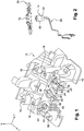
- a lighting module light module 10 which notably comprises a radiator 12, a laser light source 14 and an optical reflector 16.
- the laser-type semiconductor light source 14 is particularly capable of emitting light radiation along a main emission axis A.
- the radiator 12 shown in figure 1 is a piece made by molding of complex shape which, in addition to its heat sink function, acts here as a support for the relative positioning and fixing of the light source 14 and the optical reflector 16.
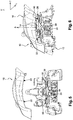
- the radiator 12 has a general design symmetry with respect to a median vertical and longitudinal plane PVM indicated in FIG. figure 7 .
- the radiator 12 is delimited by an outer envelope or surface with respect to which the light source 14 and the collector 16 are accurately positioned, in particular in order to determine a precise relative position of one component relative to the other.
- the radiator 12 comprises, for the positioning and attachment of the optical collector 16, four positioning and fixing holes 18 each of which is associated with a flat portion 20 of the outer surface of the radiator 12. Each of the holes 18 is adapted to receive complementary elements 20 of the optical collector 16.
- the radiator 12 At its forward longitudinal portion, the radiator 12 comprises a portion 24 forming a mounting plate for the laser light source 14 via a frame 26 according to the invention.
- the plate 24 is delimited by a planar upper face, here horizontal, 28 of generally rectangular contour whose length extends along the transverse axis T.
- the plate 24 comprises in its center a stepped cylindrical housing 30, here of circular section whose axis of generally vertical orientation.
- the housing 30 is delimited vertically downwards by an annular bottom 32.
- the stepped housing 30 is open radially, here in the longitudinal direction towards the front, in the form of a vertical passage 34 delimited by two opposite vertical and longitudinal facets.
- the plate 24 Symmetrically on either side of the stepped housing 30, the plate 24 has two recesses 36 shaped countersink each of which is delimited by a horizontal bottom 38.
- the plate 24 comprises a fastening stud 40 of conical truncated general shape which is delimited by a horizontal annular upper bearing surface 42, these two surfaces 42 extends coplanar with the horizontal upper face 28 of the platinum 24.
- Each fixing stud 40 has a central orifice 44 which is adapted to receive, by face, a threaded rod 48 belonging here to a fixing screw 50.
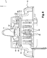
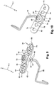
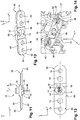
- the light source 14 is here a laser source, which is particularly illustrated in detail in FIGS. figures 7 , 9 , 10 , 11 and 13 .
- the laser source 14 comprises a housing 52 which is here of generally circular cylindrical shape and which comprises a lower flange 54 defining an annular radial shoulder 56 facing upwards.
- the housing 52 is delimited by a flat lower horizontal surface 56 in the general shape of a disc.
- the laser light source 14 comprises two connection terminals 58 for its power supply, each of which is extended by a supply wire 60.
- connection terminal 58 extends vertically downwards from the lower face 56.
- connection terminals 58 are offset by radial eccentricity with respect to the general central axis A of the housing 52 which corresponds substantially to the main axis of emission of the light source 14.
- connection terminals 58 when the light source 14 is positioned with respect to the radiator 12, is shifted transversely and longitudinally forwards with respect to the axis A.
- the mounting, positioning and fixing of the housing 52 of the laser light source 14 on the radiator 12 is carried out via the frame 26 on which the housing 52 of the laser source 14 is mounted and fixed, the mount 26 extends itself positioned and fixed on the upper face 28 of the plate 24.
- the mount 26 is here in the general form of a horizontal orientation plate and a rectangular general outline whose ends are rounded.
- the mount 26 is delimited vertically by a flat horizontal lower face 62 and by a plane horizontal upper face 64.
- the mount 26 comprises a central body 66 formed generally in excess thickness with respect to the upper face 64.
- the plate 26 is in the form of a central body 66 which is extended by two lateral fins 65 of transverse orientation, each of which is in the form of a plate.
- the central body 66 is delimited vertically downwards by a flat horizontal bottom 68 which is offset vertically upwards with respect to the plane of the lower face 62.
- the central body 66 comprises an indexing finger 70 which extends vertically downwards and which is adapted to be received in the passage 34 of the plate 24 of the radiator 12 to constitute a means of foolproofing the general orientation of the frame 26 with respect to the plate 24.
- the central body 66 has a central cylindrical housing 72 of circular contour and vertical axial orientation orthogonal to the plane of the upper face 64.
- the body 52 can be forced into the central housing 72 and / or fixed by gluing.
- the vertical position of the housing 52 with respect to the plate 26 is determined by the axial abutment upwardly of the radial shoulder 56 against the portion facing the bottom 68 of the central body 66.
- the method for mounting it also consists in ensuring a determined angular orientation of the housing 52 about its axis with respect to the plate 26 in such a way as to this is illustrated in the figure 13 , that the connection terminals 58 are eccentric and oriented as described above, in particular longitudinally forwards facing the indexing finger 70.
- the plate 26 In the vicinity of each of its opposite transverse ends, the plate 26 has a cylindrical through-fixing hole 74.
- each fixing hole 74 is substantially greater than the outside diameter of the threaded rod 48 so that the latter is received with radial clearance in the associated hole 74 for, as will be explained later, to allow adjustment, in the horizontal plane L, T, of the position of the frame 26 relative to the plate 24.
- the lower flange 54 of the housing 52 is also with radial clearance in the housing 30 of the plate 24.
- each lateral flange 65 has, between the fixing hole 74 and the central body 66, a cylindrical opening hole 76 which is a gripping hole to allow the handling of the plate 26 with respect to the radiator 12, for example by means of a manipulation head (not shown) motorized.
- the optical module 10 is equipped with a diffuser screen 80 which is illustrated in detail in FIG. figure 14 .
- the screen 80 has two opposite transverse tabs 82 each of which is received in an associated housing 36 of the plate 24 of the radiator 12, each tab 82 extends through an associated stud 40.
- the precise positioning and fixing of the light source 14 and the optical reflector 16 on the radiator 12 is carried out as follows.
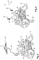
- the subassembly After having assembled and fixed the light source 14 and the mount 26, the subassembly is brought relative to the radiator 12 in the position illustrated in FIG. figure 3 .
- the plate 26, with its indexing finger 70 is brought into position relative to the plate 24 with its lower face 62 in horizontal plane support on portions vis-à-vis the upper face horizontal 28 of the plate 24.
- the passage 34 receives the indexing finger 70.
- the fixing screws 50 can be put in place and screwed after the step of adjusting the positioning of the frame 26 with respect to the plate 24.
- Such precise positioning can be provided by any known means, and for example by imaging means.
- the next step then consists in positioning and fixing the optical reflector 16 on the radiator 12 so as to precisely position and fix the optical reflector 16 with respect to the laser light source 14.
- the light source 14 is positioned directly relative to the frame 26 which acts as a reference surface for the light source, and it is positioned indirectly with respect to the optical reflector 16 which is itself positioned relative to the reference surface constituted by the radiator 12 which is the reference surface common to the frame 26 and to the optical reflector 12.
- the frame 26 may be made by for example molding of any material, plastic or metal, including aluminum alloy, Zamac, etc. ; its material being chosen in particular as a function of stress of deformation and thermal expansion.
- the frame 26 may comprise one or more light sources, each of which is precisely positioned with respect to the plate 26.
- the light source 14 may comprise a non-cylindrical housing, in any other form, the mount 26 having a housing complementary to the shape of the housing of the light source.
- Mount 26 can also be made in one piece with all or part of the light source housing.
- the frame 26 can also be secured to the light source housing by overmolding around the latter.
Landscapes
- Engineering & Computer Science (AREA)
- General Engineering & Computer Science (AREA)
- Physics & Mathematics (AREA)
- Optics & Photonics (AREA)
- Mechanical Engineering (AREA)
- General Physics & Mathematics (AREA)
- Microelectronics & Electronic Packaging (AREA)
- Non-Portable Lighting Devices Or Systems Thereof (AREA)
- Fastening Of Light Sources Or Lamp Holders (AREA)
- Semiconductor Lasers (AREA)
Applications Claiming Priority (1)
| Application Number | Priority Date | Filing Date | Title |
|---|---|---|---|
| FR1753057A FR3065053B1 (fr) | 2017-04-07 | 2017-04-07 | Module lumineux pour vehicule automobile comportant une source lumineuse a semi-conducteur |
Publications (1)
| Publication Number | Publication Date |
|---|---|
| EP3385607A1 true EP3385607A1 (de) | 2018-10-10 |
Family
ID=58993103
Family Applications (1)
| Application Number | Title | Priority Date | Filing Date |
|---|---|---|---|
| EP18165817.0A Withdrawn EP3385607A1 (de) | 2017-04-07 | 2018-04-05 | Leuchtmodul für kraftfahrzeug, das eine leuchtquelle mit halbleiter umfasst |
Country Status (5)
| Country | Link |
|---|---|
| US (1) | US20180292060A1 (de) |
| EP (1) | EP3385607A1 (de) |
| JP (1) | JP7143104B2 (de) |
| CN (1) | CN108692271A (de) |
| FR (1) | FR3065053B1 (de) |
Families Citing this family (1)
| Publication number | Priority date | Publication date | Assignee | Title |
|---|---|---|---|---|
| CN114198712A (zh) * | 2021-12-20 | 2022-03-18 | 芜湖安瑞光电有限公司 | 一种光源可调汽车灯具 |
Citations (6)
| Publication number | Priority date | Publication date | Assignee | Title |
|---|---|---|---|---|
| DE3107285A1 (de) * | 1981-02-26 | 1983-11-24 | Elwex Ltd., White Mill North, Wexford | "leuchte" |
| WO2002093228A2 (de) * | 2001-05-14 | 2002-11-21 | Milasys Gbr | Positioniereinrichtung |
| EP2693108A1 (de) * | 2012-08-03 | 2014-02-05 | Automotive Lighting Reutlingen GmbH | Lichtmodul und Verfahren zur Herstellung eines Lichtmoduls |
| EP2956335A1 (de) * | 2013-02-14 | 2015-12-23 | Zizala Lichtsysteme GmbH | Lichtmodul für einen fahrzeugscheinwerfer |
| EP3021040A1 (de) * | 2014-11-14 | 2016-05-18 | Hella KGaA Hueck & Co. | Lichtbaugruppe mit einer justierbaren trägerplatte für leuchtmittel und verfahren zur justage der trägerplatte |
| EP3147556A1 (de) * | 2015-09-24 | 2017-03-29 | Stanley Electric Co., Ltd. | Fahrzeugbeleuchtungsvorrichtung |
Family Cites Families (2)
| Publication number | Priority date | Publication date | Assignee | Title |
|---|---|---|---|---|
| JP2017062885A (ja) | 2015-09-24 | 2017-03-30 | スタンレー電気株式会社 | 車両用灯具 |
| JP2017098064A (ja) | 2015-11-24 | 2017-06-01 | スタンレー電気株式会社 | 車両用灯具 |
-
2017
- 2017-04-07 FR FR1753057A patent/FR3065053B1/fr active Active
-
2018
- 2018-04-05 EP EP18165817.0A patent/EP3385607A1/de not_active Withdrawn
- 2018-04-06 JP JP2018073929A patent/JP7143104B2/ja active Active
- 2018-04-06 US US15/946,786 patent/US20180292060A1/en not_active Abandoned
- 2018-04-08 CN CN201810309524.7A patent/CN108692271A/zh active Pending
Patent Citations (7)
| Publication number | Priority date | Publication date | Assignee | Title |
|---|---|---|---|---|
| DE3107285A1 (de) * | 1981-02-26 | 1983-11-24 | Elwex Ltd., White Mill North, Wexford | "leuchte" |
| WO2002093228A2 (de) * | 2001-05-14 | 2002-11-21 | Milasys Gbr | Positioniereinrichtung |
| EP2693108A1 (de) * | 2012-08-03 | 2014-02-05 | Automotive Lighting Reutlingen GmbH | Lichtmodul und Verfahren zur Herstellung eines Lichtmoduls |
| EP2956335A1 (de) * | 2013-02-14 | 2015-12-23 | Zizala Lichtsysteme GmbH | Lichtmodul für einen fahrzeugscheinwerfer |
| EP2956335B1 (de) * | 2013-02-14 | 2016-12-21 | ZKW Group GmbH | Lichtmodul für einen fahrzeugscheinwerfer |
| EP3021040A1 (de) * | 2014-11-14 | 2016-05-18 | Hella KGaA Hueck & Co. | Lichtbaugruppe mit einer justierbaren trägerplatte für leuchtmittel und verfahren zur justage der trägerplatte |
| EP3147556A1 (de) * | 2015-09-24 | 2017-03-29 | Stanley Electric Co., Ltd. | Fahrzeugbeleuchtungsvorrichtung |
Also Published As
| Publication number | Publication date |
|---|---|
| FR3065053B1 (fr) | 2019-10-11 |
| US20180292060A1 (en) | 2018-10-11 |
| JP2018181847A (ja) | 2018-11-15 |
| CN108692271A (zh) | 2018-10-23 |
| JP7143104B2 (ja) | 2022-09-28 |
| FR3065053A1 (fr) | 2018-10-12 |
Similar Documents
| Publication | Publication Date | Title |
|---|---|---|
| EP3201517B1 (de) | Vorrichtung zur positionierung eines moduls mit einer lichtquelle auf einer optischen vorrichtung | |
| EP3299710B1 (de) | Leuchtmodul und leuchtvorrichtung für kraftfahrzeug, das ein solches leuchtmodul umfasst | |
| FR3011784A1 (fr) | Dispositif d'eclairage ou de signalisation de vehicule automobile et procede d'assemblage correspondant | |
| FR2943856A1 (fr) | Dispositif de support pour harnais electrique a la traversee d'une structure | |
| EP3299702B1 (de) | Optisches leuchtmodul eines kraftfahrzeugs | |
| EP2966344A1 (de) | Optisches modul mit linse für kfz-scheinwerfer | |
| FR3056698B1 (fr) | Module lumineux pour vehicule automobile | |
| FR3065053B1 (fr) | Module lumineux pour vehicule automobile comportant une source lumineuse a semi-conducteur | |
| WO2011055100A2 (fr) | Support pour maintenir en position des objets allongés par rapport à une structure | |
| FR2948616A1 (fr) | Dispositif d'eclairage pour vehicule automobile | |
| FR2971980A1 (fr) | Vehicule comportant un absorbeur de choc et absorbeur de choc correspondant | |
| EP3041741B1 (de) | Strukturgehäuse, angeordnet zwischen triebwerk und triebwerksgondel, mit einer die befestigungsbolzen tragende befestigungsplatte | |
| EP4148254B1 (de) | Baugruppe für eine luftfahrzeuggondel, die eine halteplatte, einen wärmeschutz und ein befestigungssystem umfasst | |
| FR3088869A1 (fr) | Dispositif de pré-positionnement et de maintien d’un élément sur un boitier | |
| FR3026690A1 (fr) | Dispositif d'eclairage et/ou de signalisation avec fonction de signalisation laterale | |
| EP3115681A1 (de) | Leuchtmodul für kfz-scheinwerfer | |
| EP3009735A1 (de) | Leuchtmodul, das eine diode umfasst | |
| FR2768261A1 (fr) | Embase pour diode de puissance d'alternateur de vehicule automobile | |
| EP3990961B1 (de) | Optisches modul mit mikrospiegelanordnung | |
| EP0581627B1 (de) | Verfahren zur Befestigung einer Fahrzeugachse am Rahmen eines Fahrzeugs | |
| FR2921031A1 (fr) | Element de pare-chocs comprenant une peau de pare-chocs et un presseur, et vehicule automobile comprenant un tel element de pare-chocs | |
| EP3966496B1 (de) | Tageslichtsignalisierungsmodul für kraftfahrzeuge und beleuchtungs- und signalgebungsanordnung mit diesem modul | |
| FR2886614A1 (fr) | Joint peripherique d'un vitrage d'optique d'un vehicule automobile | |
| FR3056948B1 (fr) | Bloc de commande electrique pour garniture de portiere | |
| EP3356185A1 (de) | Anordnung zur montage von verschiedenen modellen von beleuchtungsmodulen auf einer bestimmten kraftfahrzeugabschirmung |
Legal Events
| Date | Code | Title | Description |
|---|---|---|---|
| PUAI | Public reference made under article 153(3) epc to a published international application that has entered the european phase |
Free format text: ORIGINAL CODE: 0009012 |
|
| STAA | Information on the status of an ep patent application or granted ep patent |
Free format text: STATUS: REQUEST FOR EXAMINATION WAS MADE |
|
| 17P | Request for examination filed |
Effective date: 20180405 |
|
| AK | Designated contracting states |
Kind code of ref document: A1 Designated state(s): AL AT BE BG CH CY CZ DE DK EE ES FI FR GB GR HR HU IE IS IT LI LT LU LV MC MK MT NL NO PL PT RO RS SE SI SK SM TR |
|
| AX | Request for extension of the european patent |
Extension state: BA ME |
|
| STAA | Information on the status of an ep patent application or granted ep patent |
Free format text: STATUS: EXAMINATION IS IN PROGRESS |
|
| 17Q | First examination report despatched |
Effective date: 20211029 |
|
| P01 | Opt-out of the competence of the unified patent court (upc) registered |
Effective date: 20230528 |
|
| STAA | Information on the status of an ep patent application or granted ep patent |
Free format text: STATUS: THE APPLICATION IS DEEMED TO BE WITHDRAWN |
|
| 18D | Application deemed to be withdrawn |
Effective date: 20230721 |