EP3385608B1 - Dispositif d'eclairage pour véhicules - Google Patents
Dispositif d'eclairage pour véhicules Download PDFInfo
- Publication number
- EP3385608B1 EP3385608B1 EP18159375.7A EP18159375A EP3385608B1 EP 3385608 B1 EP3385608 B1 EP 3385608B1 EP 18159375 A EP18159375 A EP 18159375A EP 3385608 B1 EP3385608 B1 EP 3385608B1
- Authority
- EP
- European Patent Office
- Prior art keywords
- reflector
- segments
- segment
- light distribution
- basic shape
- Prior art date
- Legal status (The legal status is an assumption and is not a legal conclusion. Google has not performed a legal analysis and makes no representation as to the accuracy of the status listed.)
- Active
Links
Images


Classifications
-
- F—MECHANICAL ENGINEERING; LIGHTING; HEATING; WEAPONS; BLASTING
- F21—LIGHTING
- F21S—NON-PORTABLE LIGHTING DEVICES; SYSTEMS THEREOF; VEHICLE LIGHTING DEVICES SPECIALLY ADAPTED FOR VEHICLE EXTERIORS
- F21S43/00—Signalling devices specially adapted for vehicle exteriors, e.g. brake lamps, direction indicator lights or reversing lights
- F21S43/30—Signalling devices specially adapted for vehicle exteriors, e.g. brake lamps, direction indicator lights or reversing lights characterised by reflectors
- F21S43/31—Optical layout thereof
-
- F—MECHANICAL ENGINEERING; LIGHTING; HEATING; WEAPONS; BLASTING
- F21—LIGHTING
- F21S—NON-PORTABLE LIGHTING DEVICES; SYSTEMS THEREOF; VEHICLE LIGHTING DEVICES SPECIALLY ADAPTED FOR VEHICLE EXTERIORS
- F21S41/00—Illuminating devices specially adapted for vehicle exteriors, e.g. headlamps
- F21S41/30—Illuminating devices specially adapted for vehicle exteriors, e.g. headlamps characterised by reflectors
- F21S41/32—Optical layout thereof
- F21S41/33—Multi-surface reflectors, e.g. reflectors with facets or reflectors with portions of different curvature
- F21S41/334—Multi-surface reflectors, e.g. reflectors with facets or reflectors with portions of different curvature the reflector consisting of patch like sectors
- F21S41/336—Multi-surface reflectors, e.g. reflectors with facets or reflectors with portions of different curvature the reflector consisting of patch like sectors with discontinuity at the junction between adjacent areas
-
- F—MECHANICAL ENGINEERING; LIGHTING; HEATING; WEAPONS; BLASTING
- F21—LIGHTING
- F21S—NON-PORTABLE LIGHTING DEVICES; SYSTEMS THEREOF; VEHICLE LIGHTING DEVICES SPECIALLY ADAPTED FOR VEHICLE EXTERIORS
- F21S41/00—Illuminating devices specially adapted for vehicle exteriors, e.g. headlamps
- F21S41/30—Illuminating devices specially adapted for vehicle exteriors, e.g. headlamps characterised by reflectors
- F21S41/32—Optical layout thereof
- F21S41/33—Multi-surface reflectors, e.g. reflectors with facets or reflectors with portions of different curvature
- F21S41/337—Multi-surface reflectors, e.g. reflectors with facets or reflectors with portions of different curvature the reflector having a structured surface, e.g. with facets or corrugations
-
- F—MECHANICAL ENGINEERING; LIGHTING; HEATING; WEAPONS; BLASTING
- F21—LIGHTING
- F21S—NON-PORTABLE LIGHTING DEVICES; SYSTEMS THEREOF; VEHICLE LIGHTING DEVICES SPECIALLY ADAPTED FOR VEHICLE EXTERIORS
- F21S43/00—Signalling devices specially adapted for vehicle exteriors, e.g. brake lamps, direction indicator lights or reversing lights
- F21S43/10—Signalling devices specially adapted for vehicle exteriors, e.g. brake lamps, direction indicator lights or reversing lights characterised by the light source
- F21S43/13—Signalling devices specially adapted for vehicle exteriors, e.g. brake lamps, direction indicator lights or reversing lights characterised by the light source characterised by the type of light source
- F21S43/14—Light emitting diodes [LED]
-
- B—PERFORMING OPERATIONS; TRANSPORTING
- B60—VEHICLES IN GENERAL
- B60Q—ARRANGEMENT OF SIGNALLING OR LIGHTING DEVICES, THE MOUNTING OR SUPPORTING THEREOF OR CIRCUITS THEREFOR, FOR VEHICLES IN GENERAL
- B60Q2800/00—Features related to particular types of vehicles not otherwise provided for
- B60Q2800/20—Utility vehicles, e.g. for agriculture, construction work
Definitions
- the invention relates to a lighting device for vehicles according to the preamble of patent claim 1.
- From the EP 1 077 344 A2 discloses a vehicle light with a plurality of light sources and reflectors assigned to the same.
- the reflectors each have a predetermined basic shape, the basic shape being formed by a plurality of facets arranged next to one another.
- the basic shape of the reflector surface is parabolic.
- a space-saving vehicle lamp for generating a predetermined light distribution can be created by the large number of light sources and reflectors assigned to them.
- a disadvantage of the known vehicle light is that the structure is relatively complex. In particular, several light sources must be arranged in different planes.
- a lighting device for vehicles which comprises a light source and a reflector.
- the Reflector has light-reflecting facets. Reflective elements are integrated in the reflector, which have a convex curvature. As a result, light beams that arrive from outside from other road users, for example other headlights, are reflected back in the same direction.
- a lighting device for vehicles which comprises a light source and a reflector.
- the reflector has highly reflective facets and low reflective sections, so that a relatively wide beam of light can be emitted.
- the reflector has a concave basic shape, with the facets of the reflector extending next to one another in segments. The faceted segments thus have the same basic shape.
- a lighting device for vehicles which has a light source and a reflector.
- the reflector has pairs of first reflector segments and second reflector segments arranged on opposite sides of the light source.
- the second reflector segments have a different basic shape in an area close to the axis than in an area remote from the axis.
- the object of the present invention is therefore to further develop a lighting device with a light source and a reflector in such a way that a predetermined homogeneous light distribution can be generated in a space-saving and cost-effective manner.
- the invention has the features of patent claim 1 in order to solve this problem.
- a reflector has a plurality of reflector segments which have different basic shapes and are therefore provided for generating different partial light distributions.
- a first reflector segment serves to generate a first partial light distribution (near-field illumination).
- a second reflector segment is used to generate a second partial light distribution (high beam illumination).
- a predetermined light distribution is provided by superimposing these partial light distributions, with a working light distribution preferably being generated if agricultural vehicles or agricultural machines are involved.
- the reflector segments are associated with the same light source, so that the resulting light distribution can be generated with a minimum of light sources.
- the first basic shape of the first reflector segment and the second basic shape of the second reflector segment are shaped in such a way that the reflector enables the generation of near-field illumination and the generation of far-field illumination.
- the near-field illumination can be generated without a lens having to have optical elements.
- the number of the first reflector segments on the one hand and the second reflector segments on the other hand is the same, with the first and second reflector segments being arranged in pairs. Reflector segments of a pair of first and second reflector segments are arranged oppositely with respect to the light source. As a result, the reflector advantageously has a relatively simple structure.
- the first and second reflector segments extend in the form of a sector of a circle at an acute annular angle in projection onto a plane running perpendicularly to the main emission direction.
- a distance between marginal edges of the respective reflector segments thus increases with increasing distance from the light source.
- the edges are straight.
- the reflector thus has a structure that is easy to manufacture and effective deflection of the luminous flux provided by the light source for generating the light distribution.
- the edge formed between the reflector segments has a width which extends to an outer
- the lighting device according to the invention is preferably used as a work light in agricultural vehicles and/or agricultural machines.
- a plurality of lighting modules are preferably arranged next to one another, with each lighting module being formed by a single light source and a single reflector.
- the light sources of the lighting modules can be arranged in a common plane on a single light source carrier. This results in space-saving and effective homogeneous illumination by the worklight.
- a lighting device according to the invention is preferably used as a work light in agricultural vehicles and/or agricultural machinery.
- the lighting device can also be used for general lighting (buildings, public space, etc.) or in or on any vehicle.
- the lighting device can also be used to generate two different light functions, for example low beam and high beam.
- the lighting device has a housing 1 in which a plurality of lighting modules 2 are arranged. An opening edge 3 of the housing 1 is connected to a transparent cover plate 5 via sealing and/or adhesive means 4 .
- the sealing and/or adhesive 4 can be designed as a silicone adhesive.
- the cover plate 5 is made of a clear plastic material or a clear glass material.
- the light modules 2 each have a light source 6 with which a single reflector 7 is assigned.
- the light source 6 is preferably designed as a semiconductor-based light source, LED light source.
- a main axis 8 of the light source 6 runs parallel to a main emission direction H of the lighting device.
- the light source 6 is arranged in a rear opening 9 of the reflector 7 .
- the light source 6 is thus arranged in a base area of the reflector 7, which opens in the main emission direction H to form a plurality of reflector segments 10, 11 up to a front edge 12 of the reflector 7.
- the reflector 7 has a pair of first reflector segments 10 Generation of a first partial light distribution T1 and a pair of second reflector segments 11 for generating a second partial light distribution T2.
- the first reflector segment 10 has a first basic shape that differs from a second basic shape of the second reflector segment 11 .
- the basic shape of the first reflector segment 10 is Parabola-shaped, so that the first partial light distribution T1 is used for near-field illumination.
- the basic shape of the second reflector segment 11 has a free-form surface, so that the second partial light distribution T2 serves to illuminate the far field.
- the basic shape of the first reflector segment 10 and/or the basic shape of the second reflector segment 11 can also have a different basic shape, for example the basic shape of the first reflector segment 10 can be free-form and the basic shape of the second reflector segment 11 can be parabolic.
- the LED light sources 6 are each arranged on a common light source carrier 26 (printed circuit board).
- the first reflector segment 10 has a multiplicity of facets 13 arranged next to one another, the dimensions of which are smaller than a multiplicity of facets 14 arranged next to one another of the second reflector segment 11.
- the first reflector segments 10 of the pair of first reflector segments 10 on the one hand and the second reflector segments 11 of the pair of second reflector segments 11 on the other hand are arranged on opposite sides of the light source 6 .
- the number of pairs of first reflector segments 10 and second reflector segments 11 is the same.
- the light modules 2 each have a single pair of first reflector segments 10 and a single pair of second reflector segments 11 . If necessary, two pairs of first reflector segments 10 and two pairs of second reflector segments 11 could also be provided.
- the first reflector segments 10 and the second reflector segments 11 each extend in an arc, in accordance with the respective basic shape, from the plane in which the light sources 6 are arranged, in the direction of the cover lens 5.
- the first reflector segment 10 and the second reflector segment 11 run in Projection onto a plane running perpendicular to the main emission direction H, which preferably runs parallel to the light source carrier 26 or a plane of extension of the light sources 6, in each case in the form of a sector of a circle at an acute annular angle ⁇ 1 or ⁇ 2 , with the annular angles ⁇ 1, ⁇ 2 in the circumferential direction U of the reflector 7 run.
- the annular angle ⁇ 1 of the first reflector segment 10 is smaller than the annular angle ⁇ 2 of the second reflector segment 11.
- the annular angle ⁇ 1 of the first reflector segment 10 is in the range of 60°, while the annular angle ⁇ 2 of the second reflector segment is in the range of 70 ° lies.
- the pair of first reflector segments 10 is arranged symmetrically to a vertical center plane M V of the reflector 7 .
- the pair of second reflector segments 11 is arranged symmetrically to a horizontal center plane M H of the reflector 7 .
- the first reflector segments 10 and the second reflector segments 11 are thus arranged alternately or alternately.
- the reflectors 7 of the light modules 2 are connected to one another in one piece.
- the overall reflector formed from the plurality of reflectors 7 only needs to be positioned and/or fastened with its side feet 15 on contact surfaces 16 of the housing 1 .
- the first reflector segments 10 and the second reflector segments 11 are each delimited by marginal edges 17 which, in projection onto a plane running perpendicularly to the main emission direction H, run outwards in a straight line.
- the edge 17 forms a connecting section between adjacent reflector segments 10, 11.
- a width b of this edge 17 is designed to be enlarged in the direction of the front edge 12 of the reflector 7. If necessary, the width b of the peripheral edge 17 or of the connecting area can also be made constant in the direction of the front edge 12 of the reflector 7 .
- a distance a from the edge edges 17 delimiting the respective reflector segments 10, 11 to one another increases from one end facing the light source 6 to the front edge 12 of the reflector 7.
- the reflector 7 surrounds the light source 6 in the circumferential direction U continuously.
- the reflector surfaces of the first reflector segments 10 are not of the same size. Because corner areas 18 of the housing 1 and the lens 5 are fully utilized by the reflector segments 10, 11 for reflecting the light. For example, the surface of the first reflector segment 10' is larger than the surface of the opposite first reflector segment 10 of the same reflector 7.
- a reflector surface of the first reflector segment 10" arranged in an opposite corner region 18 is of the same size to the reflector surface of the first reflector segment 10'.
- the size of the reflector surface is that on one side the first reflector segments 10 arranged on the light source 6 are the same size as the reflector surface of the first reflector segments 10 of the lighting modules 2 arranged on the opposite side.
- the lower second reflector segments 11' of an upper row 22 of light modules 2 and the upper second reflector segments 11' of a lower row 23 of light modules 2 are the same size and on the other hand smaller than upper second reflector segments 11" of the upper row 22 of the light modules 2 and lower reflector segments 11" of the lower row 23 of the light modules 2.
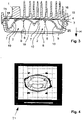
- the first reflector segments 10 of the lighting modules 2 are used to generate the first partial light distribution T1 (near-field illumination), which is shown in figure 4 is shown.
- the second reflector segments 11 of the lighting modules 2 generate a second partial light distribution T2 (far field illumination) according to FIG figure 5 .
- the in figure 6 shown total light distribution G, which represents the light distribution of the worklight.
Landscapes
- Engineering & Computer Science (AREA)
- General Engineering & Computer Science (AREA)
- Physics & Mathematics (AREA)
- Microelectronics & Electronic Packaging (AREA)
- Optics & Photonics (AREA)
- Non-Portable Lighting Devices Or Systems Thereof (AREA)
Claims (4)
- Dispositif d'éclairage pour véhicules doté d'un boîtier (1) comprenant un bord d'ouverture (3), qui est relié à une vitre de fermeture (5) transparente par le biais d'un moyen étanchéifiant et/ou adhésif (4),un certain nombre de sources de lumière (6) et de réflecteurs (7) étant disposé dans le boîtier (1),un réflecteur (7) unique étant associé à chaque source de lumière (6) pour dévier la lumière émise par la source de lumière (6) dans une direction de faisceau principale (H) du dispositif d'éclairage conformément à une répartition prédéfinie de la lumière, le réflecteur (7) comportant une surface de réflecteur avec une forme de base comprenant une pluralité de facettes (13, 14),le réflecteur (7) comportant un premier segment de réflecteur (10) comprenant une surface de réflecteur avec une première forme de base pour générer une première répartition de lumière partielle (T1) d'une part et un second segment de réflecteur (11) comprenant une surface de réflecteur avec une seconde forme de base différente pour générer une seconde répartition de lumière partielle (T2) d'autre part,la première forme de base du premier segment de réflecteur (10) étant conçue pour générer la première répartition de lumière partielle (T1) réalisée sous la forme d'un éclairage de champ proche et la seconde forme de base du second segment de réflecteur (11) étant conçue pour générer la seconde répartition de lumière partielle (T2) réalisée sous la forme d'un éclairage de champ lointain,les facettes (13) du premier segment de réflecteur (10) présentant une dimension plus petite que les facettes (14) du second segment de réflecteur (11),le réflecteur (7) comportant au moins deux premiers segments de réflecteur (10) et au moins deux seconds segments de réflecteur (11), le nombre des premiers segments de réflecteur (10) et des seconds segments de réflecteur (11) étant identique et les premiers segments de réflecteur (10) et les seconds segments de réflecteur (11) s'étendant respectivement par paires depuis des côtés opposés de la source de lumière (6) en forme d'arc en direction de la vitre de fermeture (5),une paire de premiers segments de réflecteur (10) étant disposée de manière symétrique par rapport à un plan médian vertical (MV) du réflecteur (7) et une paire de seconds segments de réflecteur (11) étant disposée de manière symétrique par rapport à un pian médian horizontal (MH) du réflecteur (7), caractérisé en ce que le premier segment de réflecteur (10) et le second segment de réflecteur (11) s'étendent, en projection sur un plan perpendiculaire à la direction de faisceau principal (H), en forme de secteur circulaire en formant un angle annulaire aigu (ϕ1, ϕ2), en ce que l'angle annulaire (ϕ1) du premier segment de réflecteur (10) est inférieur à l'angle annulaire (ϕ2) du second segment de réflecteur (11) et en ce que les premiers segments de réflecteur (10) et les seconds segments de réflecteur (11) sont disposés en alternance dans le sens circonférentiel (U) du réflecteur (7).
- Dispositif d'éclairage selon la revendication 1, caractérisé en ce qu'une arête de bord (17) est réalisée entre le premier segment de réflecteur (10) et le second segment de réflecteur (11), dont la largeur (b) augmente ou est constante en direction d'un bord avant (12) du réflecteur (7).
- Dispositif d'éclairage selon l'une quelconque des revendications 1 à 2, caractérisé en ce que la vitre de fermeture (5) est transparente et exempte d'éléments optiques.
- Utilisation du dispositif d'éclairage selon l'une quelconque des revendications 1 à 3 comme projecteur de travail pour véhicules agricoles et/ou machines agricoles, dans laquelle, pour générer la répartition de la lumière (G), un certain nombre de modules d'éclairage (2) disposés les uns à côté des autres, comprenant respectivement une source de lumière (6) unique et un réflecteur (7) unique, est prévu.
Applications Claiming Priority (1)
| Application Number | Priority Date | Filing Date | Title |
|---|---|---|---|
| DE102017105633.5A DE102017105633A1 (de) | 2017-03-16 | 2017-03-16 | Beleuchtungsvorrichtung für Fahrzeuge |
Publications (2)
| Publication Number | Publication Date |
|---|---|
| EP3385608A1 EP3385608A1 (fr) | 2018-10-10 |
| EP3385608B1 true EP3385608B1 (fr) | 2022-06-08 |
Family
ID=61563152
Family Applications (1)
| Application Number | Title | Priority Date | Filing Date |
|---|---|---|---|
| EP18159375.7A Active EP3385608B1 (fr) | 2017-03-16 | 2018-03-01 | Dispositif d'eclairage pour véhicules |
Country Status (3)
| Country | Link |
|---|---|
| US (1) | US10253942B2 (fr) |
| EP (1) | EP3385608B1 (fr) |
| DE (1) | DE102017105633A1 (fr) |
Families Citing this family (2)
| Publication number | Priority date | Publication date | Assignee | Title |
|---|---|---|---|---|
| USD839461S1 (en) * | 2016-04-11 | 2019-01-29 | HELLA GmbH & Co. KGaA | Lighting equipment for vehicles |
| US10753565B1 (en) * | 2019-12-06 | 2020-08-25 | True Parts Inc. | Vehicular headlamp reflector |
Family Cites Families (9)
| Publication number | Priority date | Publication date | Assignee | Title |
|---|---|---|---|---|
| US1751934A (en) * | 1927-11-03 | 1930-03-25 | Egarsol Glareless Reflector Co | Antiglare reflector |
| US3700883A (en) * | 1970-09-23 | 1972-10-24 | Gen Motors Corp | Faceted reflector for lighting unit |
| US4704661A (en) * | 1986-08-25 | 1987-11-03 | General Electric Company | Faceted reflector for headlamps |
| JP2878111B2 (ja) * | 1994-03-09 | 1999-04-05 | 株式会社小糸製作所 | 車両用灯具 |
| EP1077344A3 (fr) | 1999-08-16 | 2004-01-28 | FER Fahrzeugelektrik GmbH | Lampe |
| DE102009005635B4 (de) * | 2009-01-21 | 2020-01-30 | HELLA GmbH & Co. KGaA | Beleuchtungsvorrichtung für Fahrzeuge |
| DE102009035165A1 (de) * | 2009-07-29 | 2011-02-03 | Automotive Lighting Reutlingen Gmbh | Beleuchtungseinrichtung für ein Fahrzeug |
| DE102011006699B4 (de) | 2011-04-04 | 2021-05-27 | Osram Gmbh | Leuchtvorrichtung |
| US10017104B2 (en) * | 2015-06-16 | 2018-07-10 | Cnh Industrial America Llc | Headlight system for an off-road vehicle |
-
2017
- 2017-03-16 DE DE102017105633.5A patent/DE102017105633A1/de not_active Withdrawn
-
2018
- 2018-03-01 EP EP18159375.7A patent/EP3385608B1/fr active Active
- 2018-03-13 US US15/919,342 patent/US10253942B2/en active Active
Also Published As
| Publication number | Publication date |
|---|---|
| US20180266644A1 (en) | 2018-09-20 |
| EP3385608A1 (fr) | 2018-10-10 |
| DE102017105633A1 (de) | 2018-09-20 |
| US10253942B2 (en) | 2019-04-09 |
Similar Documents
| Publication | Publication Date | Title |
|---|---|---|
| DE112019003756B4 (de) | Scheinwerfervorrichtung | |
| DE69803297T2 (de) | Doppelreflektierende linse | |
| DE102013212353B4 (de) | Kraftfahrzeugbeleuchtungseinrichtung mit einer eine Einkoppeloptik und eine Transport- und Umformoptik aufweisenden Lichtleiteranordnung | |
| EP3211297B1 (fr) | Module d'éclairage en particulier pour l'eclairage routier | |
| DE102006023163A1 (de) | Beleuchtungsvorrichtung für Fahrzeuge | |
| DE102008005488A1 (de) | Scheinwerfer für Fahrzeuge | |
| EP3012521B1 (fr) | Éclairage pour un vehicule automobile | |
| DE102011054234A1 (de) | Beleuchtungsvorrichtung | |
| EP1077344A2 (fr) | Lampe | |
| DE102018110793A1 (de) | Projektionsscheinwerfer | |
| EP1912018B1 (fr) | Phares de projection pour véhicules | |
| DE102014118745A1 (de) | Scheinwerfer für Fahrzeuge | |
| DE102015203362B4 (de) | Fahrzeug-Scheinwerfer | |
| EP3385608B1 (fr) | Dispositif d'eclairage pour véhicules | |
| EP2034235B1 (fr) | Phare pour véhicules | |
| EP3765781B1 (fr) | Module de lumière pour phare de véhicule automobile | |
| EP3477193B1 (fr) | Couvercle pour un module lumineux et module lumineux | |
| DE10144000A1 (de) | Fahrzeugscheinwerfer | |
| DE102015204961B4 (de) | Projektionslichtmodul für einen Kraftfahrzeugscheinwerfer, aufweisend einen Festkörper mit einer Lichteintrittsfläche an einer Ausstülpung, zwei Lichtumlenkflächen, einer Blendenkante, einer Blendenfläche und zwei disjunkten Lichtaustrittsteilflächen | |
| DE112015000417T5 (de) | Flexible Lampenanordnung | |
| EP2253880B1 (fr) | Lampe pour véhicules | |
| DE102012215124A1 (de) | Beleuchtungseinrichtung mit Lichtquelle, Lichtleitkörper und Reflektor | |
| DE102017220488B4 (de) | Scheinwerfer für Fahrzeuge | |
| DE102010020616A1 (de) | Beleuchtungsvorrichtung für Fahrzeuge | |
| DE202016104672U1 (de) | Kraftfahrzeugleuchte mit einem linienförmige Facetten aufweisenden Reflektor |
Legal Events
| Date | Code | Title | Description |
|---|---|---|---|
| PUAI | Public reference made under article 153(3) epc to a published international application that has entered the european phase |
Free format text: ORIGINAL CODE: 0009012 |
|
| STAA | Information on the status of an ep patent application or granted ep patent |
Free format text: STATUS: THE APPLICATION HAS BEEN PUBLISHED |
|
| AK | Designated contracting states |
Kind code of ref document: A1 Designated state(s): AL AT BE BG CH CY CZ DE DK EE ES FI FR GB GR HR HU IE IS IT LI LT LU LV MC MK MT NL NO PL PT RO RS SE SI SK SM TR |
|
| AX | Request for extension of the european patent |
Extension state: BA ME |
|
| STAA | Information on the status of an ep patent application or granted ep patent |
Free format text: STATUS: REQUEST FOR EXAMINATION WAS MADE |
|
| 17P | Request for examination filed |
Effective date: 20190404 |
|
| RBV | Designated contracting states (corrected) |
Designated state(s): AL AT BE BG CH CY CZ DE DK EE ES FI FR GB GR HR HU IE IS IT LI LT LU LV MC MK MT NL NO PL PT RO RS SE SI SK SM TR |
|
| STAA | Information on the status of an ep patent application or granted ep patent |
Free format text: STATUS: EXAMINATION IS IN PROGRESS |
|
| 17Q | First examination report despatched |
Effective date: 20210414 |
|
| GRAP | Despatch of communication of intention to grant a patent |
Free format text: ORIGINAL CODE: EPIDOSNIGR1 |
|
| STAA | Information on the status of an ep patent application or granted ep patent |
Free format text: STATUS: GRANT OF PATENT IS INTENDED |
|
| INTG | Intention to grant announced |
Effective date: 20220125 |
|
| GRAS | Grant fee paid |
Free format text: ORIGINAL CODE: EPIDOSNIGR3 |
|
| GRAA | (expected) grant |
Free format text: ORIGINAL CODE: 0009210 |
|
| STAA | Information on the status of an ep patent application or granted ep patent |
Free format text: STATUS: THE PATENT HAS BEEN GRANTED |
|
| AK | Designated contracting states |
Kind code of ref document: B1 Designated state(s): AL AT BE BG CH CY CZ DE DK EE ES FI FR GB GR HR HU IE IS IT LI LT LU LV MC MK MT NL NO PL PT RO RS SE SI SK SM TR |
|
| REG | Reference to a national code |
Ref country code: AT Ref legal event code: REF Ref document number: 1497170 Country of ref document: AT Kind code of ref document: T Effective date: 20220615 Ref country code: CH Ref legal event code: EP |
|
| REG | Reference to a national code |
Ref country code: DE Ref legal event code: R096 Ref document number: 502018009842 Country of ref document: DE |
|
| REG | Reference to a national code |
Ref country code: IE Ref legal event code: FG4D Free format text: LANGUAGE OF EP DOCUMENT: GERMAN |
|
| REG | Reference to a national code |
Ref country code: LT Ref legal event code: MG9D |
|
| REG | Reference to a national code |
Ref country code: NL Ref legal event code: MP Effective date: 20220608 |
|
| PG25 | Lapsed in a contracting state [announced via postgrant information from national office to epo] |
Ref country code: SE Free format text: LAPSE BECAUSE OF FAILURE TO SUBMIT A TRANSLATION OF THE DESCRIPTION OR TO PAY THE FEE WITHIN THE PRESCRIBED TIME-LIMIT Effective date: 20220608 Ref country code: NO Free format text: LAPSE BECAUSE OF FAILURE TO SUBMIT A TRANSLATION OF THE DESCRIPTION OR TO PAY THE FEE WITHIN THE PRESCRIBED TIME-LIMIT Effective date: 20220908 Ref country code: LT Free format text: LAPSE BECAUSE OF FAILURE TO SUBMIT A TRANSLATION OF THE DESCRIPTION OR TO PAY THE FEE WITHIN THE PRESCRIBED TIME-LIMIT Effective date: 20220608 Ref country code: HR Free format text: LAPSE BECAUSE OF FAILURE TO SUBMIT A TRANSLATION OF THE DESCRIPTION OR TO PAY THE FEE WITHIN THE PRESCRIBED TIME-LIMIT Effective date: 20220608 Ref country code: GR Free format text: LAPSE BECAUSE OF FAILURE TO SUBMIT A TRANSLATION OF THE DESCRIPTION OR TO PAY THE FEE WITHIN THE PRESCRIBED TIME-LIMIT Effective date: 20220909 Ref country code: FI Free format text: LAPSE BECAUSE OF FAILURE TO SUBMIT A TRANSLATION OF THE DESCRIPTION OR TO PAY THE FEE WITHIN THE PRESCRIBED TIME-LIMIT Effective date: 20220608 Ref country code: ES Free format text: LAPSE BECAUSE OF FAILURE TO SUBMIT A TRANSLATION OF THE DESCRIPTION OR TO PAY THE FEE WITHIN THE PRESCRIBED TIME-LIMIT Effective date: 20220608 Ref country code: BG Free format text: LAPSE BECAUSE OF FAILURE TO SUBMIT A TRANSLATION OF THE DESCRIPTION OR TO PAY THE FEE WITHIN THE PRESCRIBED TIME-LIMIT Effective date: 20220908 |
|
| PG25 | Lapsed in a contracting state [announced via postgrant information from national office to epo] |
Ref country code: RS Free format text: LAPSE BECAUSE OF FAILURE TO SUBMIT A TRANSLATION OF THE DESCRIPTION OR TO PAY THE FEE WITHIN THE PRESCRIBED TIME-LIMIT Effective date: 20220608 Ref country code: LV Free format text: LAPSE BECAUSE OF FAILURE TO SUBMIT A TRANSLATION OF THE DESCRIPTION OR TO PAY THE FEE WITHIN THE PRESCRIBED TIME-LIMIT Effective date: 20220608 |
|
| PG25 | Lapsed in a contracting state [announced via postgrant information from national office to epo] |
Ref country code: NL Free format text: LAPSE BECAUSE OF FAILURE TO SUBMIT A TRANSLATION OF THE DESCRIPTION OR TO PAY THE FEE WITHIN THE PRESCRIBED TIME-LIMIT Effective date: 20220608 |
|
| PG25 | Lapsed in a contracting state [announced via postgrant information from national office to epo] |
Ref country code: SM Free format text: LAPSE BECAUSE OF FAILURE TO SUBMIT A TRANSLATION OF THE DESCRIPTION OR TO PAY THE FEE WITHIN THE PRESCRIBED TIME-LIMIT Effective date: 20220608 Ref country code: SK Free format text: LAPSE BECAUSE OF FAILURE TO SUBMIT A TRANSLATION OF THE DESCRIPTION OR TO PAY THE FEE WITHIN THE PRESCRIBED TIME-LIMIT Effective date: 20220608 Ref country code: RO Free format text: LAPSE BECAUSE OF FAILURE TO SUBMIT A TRANSLATION OF THE DESCRIPTION OR TO PAY THE FEE WITHIN THE PRESCRIBED TIME-LIMIT Effective date: 20220608 Ref country code: PT Free format text: LAPSE BECAUSE OF FAILURE TO SUBMIT A TRANSLATION OF THE DESCRIPTION OR TO PAY THE FEE WITHIN THE PRESCRIBED TIME-LIMIT Effective date: 20221010 Ref country code: EE Free format text: LAPSE BECAUSE OF FAILURE TO SUBMIT A TRANSLATION OF THE DESCRIPTION OR TO PAY THE FEE WITHIN THE PRESCRIBED TIME-LIMIT Effective date: 20220608 Ref country code: CZ Free format text: LAPSE BECAUSE OF FAILURE TO SUBMIT A TRANSLATION OF THE DESCRIPTION OR TO PAY THE FEE WITHIN THE PRESCRIBED TIME-LIMIT Effective date: 20220608 |
|
| PG25 | Lapsed in a contracting state [announced via postgrant information from national office to epo] |
Ref country code: PL Free format text: LAPSE BECAUSE OF FAILURE TO SUBMIT A TRANSLATION OF THE DESCRIPTION OR TO PAY THE FEE WITHIN THE PRESCRIBED TIME-LIMIT Effective date: 20220608 Ref country code: IS Free format text: LAPSE BECAUSE OF FAILURE TO SUBMIT A TRANSLATION OF THE DESCRIPTION OR TO PAY THE FEE WITHIN THE PRESCRIBED TIME-LIMIT Effective date: 20221008 |
|
| REG | Reference to a national code |
Ref country code: DE Ref legal event code: R097 Ref document number: 502018009842 Country of ref document: DE |
|
| PG25 | Lapsed in a contracting state [announced via postgrant information from national office to epo] |
Ref country code: AL Free format text: LAPSE BECAUSE OF FAILURE TO SUBMIT A TRANSLATION OF THE DESCRIPTION OR TO PAY THE FEE WITHIN THE PRESCRIBED TIME-LIMIT Effective date: 20220608 |
|
| PLBE | No opposition filed within time limit |
Free format text: ORIGINAL CODE: 0009261 |
|
| STAA | Information on the status of an ep patent application or granted ep patent |
Free format text: STATUS: NO OPPOSITION FILED WITHIN TIME LIMIT |
|
| PG25 | Lapsed in a contracting state [announced via postgrant information from national office to epo] |
Ref country code: DK Free format text: LAPSE BECAUSE OF FAILURE TO SUBMIT A TRANSLATION OF THE DESCRIPTION OR TO PAY THE FEE WITHIN THE PRESCRIBED TIME-LIMIT Effective date: 20220608 |
|
| 26N | No opposition filed |
Effective date: 20230310 |
|
| PG25 | Lapsed in a contracting state [announced via postgrant information from national office to epo] |
Ref country code: SI Free format text: LAPSE BECAUSE OF FAILURE TO SUBMIT A TRANSLATION OF THE DESCRIPTION OR TO PAY THE FEE WITHIN THE PRESCRIBED TIME-LIMIT Effective date: 20220608 |
|
| PG25 | Lapsed in a contracting state [announced via postgrant information from national office to epo] |
Ref country code: MC Free format text: LAPSE BECAUSE OF FAILURE TO SUBMIT A TRANSLATION OF THE DESCRIPTION OR TO PAY THE FEE WITHIN THE PRESCRIBED TIME-LIMIT Effective date: 20220608 |
|
| REG | Reference to a national code |
Ref country code: CH Ref legal event code: PL |
|
| GBPC | Gb: european patent ceased through non-payment of renewal fee |
Effective date: 20230301 |
|
| REG | Reference to a national code |
Ref country code: BE Ref legal event code: MM Effective date: 20230331 |
|
| PG25 | Lapsed in a contracting state [announced via postgrant information from national office to epo] |
Ref country code: LU Free format text: LAPSE BECAUSE OF NON-PAYMENT OF DUE FEES Effective date: 20230301 |
|
| REG | Reference to a national code |
Ref country code: IE Ref legal event code: MM4A |
|
| PG25 | Lapsed in a contracting state [announced via postgrant information from national office to epo] |
Ref country code: GB Free format text: LAPSE BECAUSE OF NON-PAYMENT OF DUE FEES Effective date: 20230301 |
|
| PG25 | Lapsed in a contracting state [announced via postgrant information from national office to epo] |
Ref country code: LI Free format text: LAPSE BECAUSE OF NON-PAYMENT OF DUE FEES Effective date: 20230331 Ref country code: IE Free format text: LAPSE BECAUSE OF NON-PAYMENT OF DUE FEES Effective date: 20230301 Ref country code: GB Free format text: LAPSE BECAUSE OF NON-PAYMENT OF DUE FEES Effective date: 20230301 Ref country code: CH Free format text: LAPSE BECAUSE OF NON-PAYMENT OF DUE FEES Effective date: 20230331 |
|
| PG25 | Lapsed in a contracting state [announced via postgrant information from national office to epo] |
Ref country code: BE Free format text: LAPSE BECAUSE OF NON-PAYMENT OF DUE FEES Effective date: 20230331 |
|
| REG | Reference to a national code |
Ref country code: AT Ref legal event code: MM01 Ref document number: 1497170 Country of ref document: AT Kind code of ref document: T Effective date: 20230301 |
|
| PG25 | Lapsed in a contracting state [announced via postgrant information from national office to epo] |
Ref country code: AT Free format text: LAPSE BECAUSE OF NON-PAYMENT OF DUE FEES Effective date: 20230301 |
|
| PG25 | Lapsed in a contracting state [announced via postgrant information from national office to epo] |
Ref country code: AT Free format text: LAPSE BECAUSE OF NON-PAYMENT OF DUE FEES Effective date: 20230301 |
|
| PG25 | Lapsed in a contracting state [announced via postgrant information from national office to epo] |
Ref country code: BG Free format text: LAPSE BECAUSE OF FAILURE TO SUBMIT A TRANSLATION OF THE DESCRIPTION OR TO PAY THE FEE WITHIN THE PRESCRIBED TIME-LIMIT Effective date: 20220608 |
|
| PG25 | Lapsed in a contracting state [announced via postgrant information from national office to epo] |
Ref country code: BG Free format text: LAPSE BECAUSE OF FAILURE TO SUBMIT A TRANSLATION OF THE DESCRIPTION OR TO PAY THE FEE WITHIN THE PRESCRIBED TIME-LIMIT Effective date: 20220608 |
|
| PG25 | Lapsed in a contracting state [announced via postgrant information from national office to epo] |
Ref country code: CY Free format text: LAPSE BECAUSE OF FAILURE TO SUBMIT A TRANSLATION OF THE DESCRIPTION OR TO PAY THE FEE WITHIN THE PRESCRIBED TIME-LIMIT; INVALID AB INITIO Effective date: 20180301 |
|
| PG25 | Lapsed in a contracting state [announced via postgrant information from national office to epo] |
Ref country code: HU Free format text: LAPSE BECAUSE OF FAILURE TO SUBMIT A TRANSLATION OF THE DESCRIPTION OR TO PAY THE FEE WITHIN THE PRESCRIBED TIME-LIMIT; INVALID AB INITIO Effective date: 20180301 |
|
| PG25 | Lapsed in a contracting state [announced via postgrant information from national office to epo] |
Ref country code: TR Free format text: LAPSE BECAUSE OF FAILURE TO SUBMIT A TRANSLATION OF THE DESCRIPTION OR TO PAY THE FEE WITHIN THE PRESCRIBED TIME-LIMIT Effective date: 20220608 |
|
| PGFP | Annual fee paid to national office [announced via postgrant information from national office to epo] |
Ref country code: FR Payment date: 20251231 Year of fee payment: 9 |
|
| PGFP | Annual fee paid to national office [announced via postgrant information from national office to epo] |
Ref country code: DE Payment date: 20260102 Year of fee payment: 9 |
|
| PGFP | Annual fee paid to national office [announced via postgrant information from national office to epo] |
Ref country code: IT Payment date: 20260220 Year of fee payment: 9 |