EP3385658A1 - Suppresseur d'arme à feu multi-chicanes - Google Patents
Suppresseur d'arme à feu multi-chicanes Download PDFInfo
- Publication number
- EP3385658A1 EP3385658A1 EP18161158.3A EP18161158A EP3385658A1 EP 3385658 A1 EP3385658 A1 EP 3385658A1 EP 18161158 A EP18161158 A EP 18161158A EP 3385658 A1 EP3385658 A1 EP 3385658A1
- Authority
- EP
- European Patent Office
- Prior art keywords
- tubular housing
- elongate tubular
- tubes
- suppressor
- firearm
- Prior art date
- Legal status (The legal status is an assumption and is not a legal conclusion. Google has not performed a legal analysis and makes no representation as to the accuracy of the status listed.)
- Granted
Links
Images





Classifications
-
- F—MECHANICAL ENGINEERING; LIGHTING; HEATING; WEAPONS; BLASTING
- F41—WEAPONS
- F41A—FUNCTIONAL FEATURES OR DETAILS COMMON TO BOTH SMALLARMS AND ORDNANCE, e.g. CANNONS; MOUNTINGS FOR SMALLARMS OR ORDNANCE
- F41A21/00—Barrels; Gun tubes; Muzzle attachments; Barrel mounting means
- F41A21/30—Silencers
-
- F—MECHANICAL ENGINEERING; LIGHTING; HEATING; WEAPONS; BLASTING
- F41—WEAPONS
- F41A—FUNCTIONAL FEATURES OR DETAILS COMMON TO BOTH SMALLARMS AND ORDNANCE, e.g. CANNONS; MOUNTINGS FOR SMALLARMS OR ORDNANCE
- F41A21/00—Barrels; Gun tubes; Muzzle attachments; Barrel mounting means
- F41A21/28—Gas-expansion chambers; Barrels provided with gas-relieving ports
-
- F—MECHANICAL ENGINEERING; LIGHTING; HEATING; WEAPONS; BLASTING
- F41—WEAPONS
- F41A—FUNCTIONAL FEATURES OR DETAILS COMMON TO BOTH SMALLARMS AND ORDNANCE, e.g. CANNONS; MOUNTINGS FOR SMALLARMS OR ORDNANCE
- F41A21/00—Barrels; Gun tubes; Muzzle attachments; Barrel mounting means
- F41A21/44—Insulation jackets; Protective jackets
Definitions
- Embodiments of the subject matter disclosed herein relate to firearm sound suppressors and, more particularly to employing a plurality of baffles in a firearm sound suppressor.
- Firearms utilize high pressure exhaust gasses to accelerate a projectile such as a bullet.
- Firearm silencers hereafter referred to as "suppressors"
- These high pressure exhaust gasses are the product of burning nitrocellulose and possess significant energy that is used to accelerate the projectile.
- the typical exhaust gas pressure of a rifle cartridge in a full length barrel may be in the range of 7-10Ksi.
- a short barreled rifle may have exhaust gas pressures in the 10-20Ksi range.
- the exhaust gasses provide the energy to launch the projectile and also result in the emanation of high-decibel noises typically associated with the discharge of firearms.
- firearm suppressors lower the kinetic energy and pressure of the propellant gasses and thereby reduce the decibel level of the resultant noises.
- Firearms suppressors are mechanical pressure reduction devices that contain a center through-hole to allow passage of the projectile.
- Suppressor design(s) utilize static geometry to induce pressure loss across the device by means that may include rapid expansion and contraction, minor losses related to inlet and outlet geometry, and induced pressure differential to divert linear flow.
- Suppressors can be thought of as "in-line” pressure reduction devices that capture and release the high pressure gasses over a time (T).
- Typical suppressor design approaches used to optimize firearms noise reduction include maximizing internal volume, and providing a baffled or "tortured" pathway for propellant gas egress. Each of these approaches must be balanced against the need for clear egress of the projectile, market demand for small overall suppressor size, adverse impacts on the firearms performance, and constraints related to the firearms original mechanical design.
- Baffle structures within a suppressor provide the "tortured" pathways which act to restrain the flow of propellant gasses and thereby reduce the energy signature of said gasses.
- the baffle structures in a suppressor are typically the portion of a suppressor that absorbs the most heat from propellant gasses during firing.
- the "mirage” effect is distortion of the sight picture caused by hot air rising off of the hot suppressor directly in front of the aiming optic on the firearm.
- the "mirage” effect is a well know negative aspect of using a suppressor with a firearm, and is often mitigated by wrapping the suppressor in an insulating wrap.
- baffled gas exhaust tubes each of which reside in their own internal tube, are employed to reduce the pressure of the propellant gasses.
- the baffled exhaust tubes are positioned such that the tubes are not tangent with (touching) an interior surface of the outer wall or each other.
- the plurality of baffled exhaust gas tubes are instead contained within fluted spiral structures that follow a rifling pattern about a central axis along the longitudinal length of the suppressor's inner body wall.
- these tubes may be non-coaxial tubes relative to the central axis of the suppressor. Moreover, these tubes may be spaced away from an interior surface of the suppressor's inner body wall and these tubes may not contact the interior surface of the suppressor's inner body wall.
- this positioning maximizes the surface area of the plurality of baffled exhaust gas tubes inside the suppressor body to maximize thermal transmission between the hot exhaust gases and the suppressor body. This positioning further helps to more evenly distribute the heat energy of the hot exhaust gases to the interior structures of the suppressor body such that "hot spots" are minimized. In addition, the positioning minimizes the thermal transmission between the internal baffled exhaust gas tubes and the outer wall; a lumen defined by the area between the inner surface of the suppressors' outer wall and the outer walls of the baffled exhaust gas tubes creates a thermal buffer. As a result, thermal transmission from the high heat area of the baffled exhaust tubes to the outside wall is minimized. By delaying the heating of the suppressors' outer wall, the "mirage” effect to the shooter is delayed, allowing the operator to shoot more cartridges before the "mirage” effect occludes the view through the optic.
- Autoloading firearms both semi-automatic and automatic, are designed to utilize a portion of the waste exhaust gasses to operate the mechanical action of the firearms.
- the mechanical action of the firearm automatically ejects the spent cartridge case and emplaces a new cartridge case into the chamber of the firearms barrel.
- One typical autoloading design taps and utilizes exhaust gasses from a point along the firearms barrel. The tapped gasses provide pressure against the face of a piston, which in turn triggers the mechanical autoloading action of the firearm. The energy of the tapped exhaust gasses supplies the work required to operate the mechanical piston of the firearm enabling rapid cycling of cartridges.
- the inventors herein have recognized significant issues arising when suppressors are employed on autoloading firearms.
- use of a suppressor may result in sustained elevated internal pressures which result in transmission of excess work energy to the piston during the course of operation.
- T extended time
- the excess work energy may lead to opening of the breech (chamber) sooner than is supported by the original firearms design. Therefore, as recognized by the inventors herein, overcoming this issue requires achieving the desired pressure loss ( ⁇ P) over an abbreviated time (T) such that the internal pressure returns below the pressure threshold of the piston before firing of the subsequent cartridge.
- the issues described above may be addressed by a suppressor comprising a geometric baffle system and further comprising an auxiliary system of a plurality of baffled exhaust gas tubes that may achieve the desired pressure loss ( ⁇ P) over an abbreviated time period ( ⁇ T).
- the suppressor may be of a unitary design generated by 3D printing.
- the issues described above may be addressed by a suppressor comprising a plurality of exhaust vents that efficiently direct the exhaust gasses outward through the front of the suppressor and away from the operator and the firearm.
- the auxiliary baffled exhaust tubes may exit in any direction. Exiting out the front of the suppressor was chosen as this was the direction opposite the operator. There could be a scenario where this is suboptimal and other directions would be considered. For example, it may be desirable to have the exhaust gasses exit out of the side of the suppressor or on only one side to minimize exhaust gas occluding sensors on remote weapon platforms.
- the firearm suppressor may be operable on any type of autoloading firearms, including but not limited to machine gun applications, without adversely affecting mechanical operations according to the original firearms design. Further, the firearm suppressor may be operable without adversely impacting the safety or performance of the operator. The utility of the suppressor may therefore be extended and more fully realized.
- Other elements of the disclosed embodiments of the present subject matter are provided in detail herein.
- the suppressor may be operatively configured to be attached to a firearm.
- the suppressor may include a tubular housing body defining a longitudinal or central axis, wherein the baffle sections and further wherein the spiral fluting sections and further wherein the auxiliary system of baffled exhaust gas tubes of the suppressor are integrated and encased within a parent tubular housing component.
- the interior baffle section(s) may be surrounded by a housing such that the efficiency and efficacy of the suppressor are maintained.
- the tubular housing body may further comprise a projectile entrance portion and a projectile exit portion disposed at a longitudinally rearward region and a longitudinally forward region, respectively.
- the rearward end of the suppressor may have an opening sufficiently large enough to permit passage of at least a portion of a firearm barrel, where the suppressor may attach via connectable interaction devices such as interlacing threads.
- drawings are to scale, although other relative dimensions may be used, if desired.
- the drawings may depict components directly touching one another and in direct contact with one another and/or adjacent to one another, although such positional relationships may be modified, if desired. Further, the drawings may show components spaced away from one another without intervening components therebetween, although such relationships again, could be modified, if desired.
- An example multi-baffled firearm suppressor is described herein.
- the following description relates to various embodiments of the sound suppressor as well as methods of manufacturing and using the device.
- Potential advantages of one or more of the example approaches described herein relate to reducing a time required for the suppressor to return to ambient pressure without adversely impacting performance of the firearm, reducing a mirage effect, improving thermal signature reduction characteristics, improving operating performance with autoloading firearms, eliminating rearward venting of exhaust gasses during use with semi-automatic weapon and various others as explained herein.
- the multi-baffled firearm suppressor may be coupled to a firearm, as described at FIGS. 1 , 5 & 14 .
- the multi-baffled firearm suppressor may comprise a system of a plurality of baffled exhaust tubes as shown at FIGS. 2-5 .
- These baffled exhaust tubes may be advantageous for suppressing the overall signatures of the firearm by minimizing the time required for the system to return to ambient pressure, while also maximizing the surface area of structures inside the suppressor, and further minimizing thermal transmission between the internal structures and the outer wall of the tubular housing.
- FIGS. 1-14 show the relative positioning of various components of the suppressor assembly. If shown directly contacting each other, or directly coupled, then such components may be referred to as directly contacting or directly coupled, respectively, at least in one example. Similarly, components shown contiguous or adjacent to one another may be contiguous or adjacent to each other, respectively, at least in one example. As an example, components lying in face-sharing contact with each other may be referred to as in face-sharing contact or physically contacting one another. As another example, elements positioned apart from each other with only a space there-between and no other components may be referred to as such, in at least one example.
- top/bottom, upper/lower, above/below may be relative to a vertical axis of the figures and used to describe positioning of elements of the figures relative to one another.
- elements shown above other elements are positioned vertically above the other elements, in one example.
- shapes of the elements depicted within the figures may be referred to as having those shapes (e.g., such as being triangular, helical, straight, planar, curved, rounded, spiral, angled, or the like).
- elements shown intersecting one another may be referred to as intersecting elements or intersecting one another, in at least one example.
- an element shown within another element or shown outside of another element may be referred as such, in one example.
- FIGS. 1-14 will be described collectively.
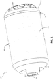
- FIG. 1 an exterior view of a first example suppressor assembly 100 according to one or more embodiments of the current disclosure is shown.
- the exterior view of the suppressor assembly 100 is shown in order to illustrate the overall shape of the suppressor and relative spatial positioning.
- the suppressor assembly 100 may comprise an elongate tubular housing 102, a rearward region 104, an outer surface 106, a forward region 108, a plurality of exhaust gas venting ports 110, projectile entrance passage 112, and junction 114.
- the suppressor of FIG. 1 may comprise a projectile entrance passage 112 forming a generally annular channel at the rearward region 104 wherethrough a projectile such as a bullet may enter to pass through and exit the suppressor 100 at the forward region 108.
- the junction 114 is the circumferential area of the suppressor 100 where the elongate tubular housing 102 and helical baffle assembly 200, which is described in detail below, join together.
- the forward region 108 tapers from the junction 114 toward the forward most region of the assembly at an approximate 45 degree angle. The forward region 108 then abruptly flattens out forward of the exhaust gas venting ports 110.
- the plurality of exhaust gas venting ports 110 are triangular shaped openings, positioned circumferentially within the forward region 108, midway between the junction 114 and the forward most end of the suppressor 100.
- the longitudinally rearward region 104 contains the projectile entrance passage 112, an opening sufficiently large enough to permit passage of at least a portion of a firearm barrel, where the suppressor 100 may attach via connectable interaction devices such as interlacing threads.
- FIG. 2 shows a view of a second example suppressor assembly according to one or more embodiments of the present disclosure, where an elongate tubular housing 102 and a helical baffle assembly 200 of the example suppressor assembly 100 are shown separated from one another for viewing purposes.
- the elongate tubular housing 102 may comprise a plurality of baffle tubes 220, baffle tube exit passages 226, a junction 202, first spiral flute section 204, second spiral flute section 206, and third spiral flute section 208.
- the figure further illustrates the helical baffle assembly 200 which may comprise a junction 202, projectile exit passage 212, first baffle section 214, second baffle section 216, third baffle section 218, and forward region 108 which contains the plurality of exhaust gas venting ports 110.
- the helical triangular nature of the baffle assembly 200 as well as the triangular helical nature of each baffle assembly component is shown in FIG. 2 .
- the helical triangular nature of the baffle assembly 200 as well as the triangular helical nature of each baffle assembly component is shown in FIG. 2 .
- the figure illustrates the manner in which the spiral flute sections 204, 206 and 208 follow a rifling pattern about a central axis along the longitudinal length of the suppressors' inner body wall. Further, the figure illustrates the junction 230 where the spiral fluting sections are tangent with the suppressors' inner wall.
- FIG. 2 illustrates in some embodiments the manner in which the plurality of baffle tubes 220 are positioned non-tangentially away from the inner wall of the tubular housing 102 and contained within the spiral fluted sections 204, 206 and 208. As may be seen in the example shown in FIG. 2 , these baffle tubes 220 are arranged non-coaxially relative to a central axis of the elongate tubular housing 102.
- the relative positioning of the baffle tubes 220 away from the inner wall thereby forms a lumen defined by the inner wall of the tubular housing 102 and the outer walls of the baffle tubes 220 and spiral fluted sections 204, 206 and 208.
- This lumen provides a thermal barrier between the baffle tubes 220 and outer wall of the tubular housing 102. Further, this lumen provides a non-baffled cavity which, due to the shaping of the spiral fluting sections, directs excess exhaust gasses forward through the suppressor in a rifling pattern toward the exhaust gas venting ports 110.
- exhaust gas baffle tubes 220 do not provide egress for the projectile, their shape and internal structure is extremely flexible and may include other shapes and provide other directions for exhaust gas egress not illustrated. Exiting of exhaust gasses out through the forward region 108 of the suppressor 100 was chosen as this was the direction opposite the operator. There could be other scenarios where this would be suboptimal and other exit directions, such as the side(s) of the suppressor, could be designed.
- the structure and positioning of the plurality of baffle tubes 220 are critical for the overall performance of the suppressor 100 in restraining and absorbing energy of the propellant gasses.
- the combined auxiliary baffle tubes 220 provide a significant reduction in the overall mass flow rate of the exhaust gasses and therefore a reduction of the overall energy signatures of the firearm. Further, the positioning of the baffle tubes 220 enables heat transmission from the exhaust gasses to the interior body of the suppressor, and minimizes heat transmission to the outer walls of the suppressor 100.
- FIG. 2 further illustrates that in some embodiments the exhaust gas venting ports 110 are further positioned forward of and aligned over the baffle tube exit passages 226. Positioning and shaping of the exhaust venting ports 110 is critical so as to facilitate rapid and efficient movement of exhaust gasses forward through, out and away from the suppressor body.
- the housing may be manufactured via processes including but not limited to, 3-D printing (e.g. selective laser melting (SLM), fused deposition modeling (FDM), sterolithography (SLA) and laminated object manufacturing (LOM)), casting, molding, and additive manufacturing.
- 3-D printing e.g. selective laser melting (SLM), fused deposition modeling (FDM), sterolithography (SLA) and laminated object manufacturing (LOM)
- SLM selective laser melting
- FDM fused deposition modeling
- SLA sterolithography
- LOM laminated object manufacturing
- the tubular housing 102 may be coupled with the helical baffle assembly 200 to form a suppressor assembly. Further, in some embodiments, the elongate tubular housing 102 and the baffle assembly 200 may be formed together such that a unitary, uninterrupted, and contiguous surface is achieved. In at least one example, the tubular housing 102 may be removably coupled with the helical baffle assembly 200 to form a suppressor assembly. However, in other examples, the tubular housing 102 may be permanently formed with the helical baffle assembly 200 to form a suppressor assembly. For example, the helical baffle assembly 200 and the tubular housing 102 may be welded to one another to form a permanent connection between the helical baffle assembly 200 and the tubular housing 102. In other examples, the helical baffle assembly 200 and the tubular housing 102 may be formed integrally in a single piece via additive manufacturing such as 3D printing, for example.
- the helical baffle assembly 200 may comprise a projectile exit opening 213 for passage of a projectile traveling through the suppressor assembly during a firing event, for example.
- the helical baffle assembly 200 may further include one or more exhaust gas venting ports 110 positioned about a circumference of the helical baffle assembly 200.
- FIG. 3 in FIG. 3 a cross-sectional view of the elongate tubular housing 102 is shown for viewing purposes.
- lumen 302 is formed between an exterior surface 305 of the baffle tubes 220 and an interior surface 303 of the elongate tubular housing 102 for a majority of a length of the baffle tubes 220.
- exhaust gas may be flowed through the baffle tubes 220.
- flared projection 304, threads 306, plurality of exhaust gas baffle tubes 220, and helical fluting sections 204, 206 and 208 may be seen positioned within the elongate tubular housing 102 of FIG. 3 .
- These helical fluting sections 204, 206, 208 may be positioned between a portion of the baffle tubes 220 and the inner surface of the elongate tubular housing.
- the exhaust gas baffle tubes 220 may be positioned within a helical fluted section 204, 206, 208.
- the helical fluting sections 204, 206, 208 may further surround a projectile path through the elongate tubular housing 102, in at least one example.
- a projectile such as a bullet, may pass through projectile entrance passage 112, where the projectile entrance passage 112 is positioned at a rearward region 104 of the elongate tubular housing 102.
- the projectile may then pass along a length of the elongate tubular housing and exit via exit passage 212.
- a path through which the projectile travels within the elongate housing 102 may be approximately along a central axis 103 of the elongate tubular passage, and the helical fluting sections 204, 206, 208 may surround the path through which the projectile travels.
- Exhaust gas from the combustion event propelling the projectile through the projectile entrance 112 may be flowed at least in part through one or more of the baffle tubes 220.
- the baffle tubes 220 By flowing the exhaust gas through one or more of the baffle tubes 220, which are spaced away from the interior surface of the elongate tubular housing 102, a mirage effect that may typically occur with the firearm may be prevented.
- the baffle tubes 220 may not contact the interior surface 303 of the elongate tubular housing 102, thus reducing an amount of heat transfer from the exhaust gas to the elongate tubular housing 102 and reducing a mirage effect.
- the baffled tubes 220, as well as the helical fluting sections 204, 206, 208 may effectively reduce a sound produced by the combustion.
- FIG. 4 illustrates a cross-cut view of the elongate tubular housing 102 which more clearly shows the interior of the suppressor.
- the plurality of exhaust gas baffle tubes 220 is clearly visible.
- Each of the exhaust gas baffle tubes 220 shown in the embodiment illustrated are clearly not tangent with each other, located away from the inner wall of the tubular housing 102, and encased within the spiral fluted sections 204, 206, and 208.
- the baffle tubes 220 are arranged non-coaxially relative to a central axis 103 of the elongate tubular housing 102.
- a central axis 105a, 105b of each of the baffle tubes 220 is approximately parallel to the central axis 103 of the elongate tubular housing 102.
- FIG. 5 a cross-sectional view of the elongate tubular housing 102 similar to FIG. 3 is shown.
- the baffle tube projections 502, and angled baffle tube projections 504 are visible inside the cut-away of the sample exhaust gas baffle tubes 220.
- an end of the angled tube projections most proximal to the central axis 105a, 105b of the baffle tube 220 within which the angled tube projection 504 is positioned is substantially parallel to this central axis.
- all of the baffle tube projections 502 and angled baffle tube projections 504 extend towards the central axis 105a, 105b of the baffle tube 220 within which they are positioned.
- the figure also illustrates the baffle tube lumen 506, threads 508, flared projections 510, baffle tube entrance 512, as well as the lumen 514 defined by the inner wall of the suppressor and outer walls of the baffle tubes 220.
- the helical baffle assembly 200 may comprise a first baffle section 214, second baffle section 216, and third baffle section 218.
- the helical triangular nature of the baffle assembly 200 as well as the triangular helical nature of each baffle assembly component is shown in FIG. 6 .
- the figure further illustrates the inner surface 602 of the endcap.
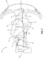
- FIG. 7 a cross-sectional cut-away view of FIG. 6 is provided.
- the interior components of the helical baffle assembly 200 are more clearly visible.
- the u-shaped grooves 702 are staggered such that they do not line up and coincide with one another. This staggering of grooves that may act as guidance or support grooves in one embodiment may allow for enhanced dispersal and/or dissipation of propellant gases.
- the u-shaped grooves may be disposed axially along a central axis of the suppressor and may be disposed longitudinally behind a forward projectile exit passage 112.
- the exit passage 112 may be disposed within the center of a front face of the forward baffle section, the front face may further define a forward region 108 of the suppressor 100.
- FIG. 8 an exploded view of the components of the helical baffle assembly 200 is provided.
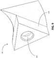
- FIG. 9 provides an enlarged perspective view of the first baffle section 214.
- FIG. 10 provides an enlarged perspective view of the second baffle section 216.
- the hollow void space 704 that is defined by an inner surface of the baffle section and the u-shaped groove 702 may be more readily visible.
- the hollow void space 704 within the baffle section 216 may comprise a complex geometry and may serve to better disperse and/or distribute propellant gas pressure and/or heat.
- FIG. 11 provides an enlarged perspective view of the third baffle section 218.
- the hollow void space 704 that is defined by an inner surface of the baffle section and the u-shaped groove 702 may be more readily visible.
- the hollow void space 704 within the baffle section 216 may comprise a complex geometry and may serve to better disperse and/or distribute propellant gas pressure and/or heat.
- FIG. 12 provides an enlarged rear perspective view of end cap 108.
- FIG. 13 provides an enlarged side perspective view of end cap 108.
- FIG. 14 provides an enlarged cross-sectional view of end cap 108.
- the energy suppressor and/or combination of the energy suppressor and firearm disclosed herein and the methods of making them have several advantages, such as: (1) they reduce the time required to achieve a pressure reduction of the exhaust gasses of the firearm thereby avoiding mechanical malfunction of autoloading firearms; (2) they reduce the mirage effect by minimizing the thermal transfer from the baffle exhaust gas tubes to the outer wall of the suppressor; (3) they improve accuracy and reliability; (4) they aid in the dissipation of heat and reduce the tendency of the energy suppressor to overheat; and (5) they can be manufactured reliably and predictably with desirable characteristics in an economical manner.
- firearm sound suppressor described and illustrated herein represents only example embodiments. It is appreciated by those skilled in the art that various changes and additions can be made to such firearm sound suppressor without departing from the spirit and scope of this disclosure.
- the firearm sound suppressor could be constructed from lightweight and durable materials not described.
- the sound suppressor may be coupled with a firearm.
- the sound suppressor may comprise an elongate tubular housing, a projectile entrance passage positioned at a rearward region of the elongate tubular housing, and a plurality of tubes positioned within the elongate tubular housing, where the plurality of tubes are spaced away from an interior surface of the elongate tubular housing.
- each of the plurality of tubes comprises a plurality of projections positioned therein.
- the plurality of projections may extend towards a central axis of the respective tube within which they are positioned.
- the plurality of tubes do not contact an interior surface of the elongate tubular housing.
- the plurality of tubes may be positioned within the elongate tubular housing without contacting the interior surface of the elongate tubular housing.
- the sound suppressor may comprise at least one helical fluted section positioned within the elongate tubular housing, wherein a portion of the helical fluted section is positioned between a portion of at least one of the plurality of tubes and the interior surface of the elongate tubular housing.
- a lumen may be formed between a majority of a length of the plurality of tubes and the interior surface of the elongate tubular housing.
- sections where the helical fluted section may be positioned between one of the tubes and the interior surface of the elongate tubular housing may be minimal.
- the sound suppressor may further comprise a plurality of exhaust gas venting ports formed into a forward region of the elongate tubular housing, each of the plurality of tubes communicating with a separate exhaust gas venting port of the plurality of exhaust gas venting ports.
- Such exhaust gas venting ports may help to efficiently reduce a pressure due to exhaust gas within the sound suppressor, thus reducing a noise caused by a firing event.
- the exhaust gas venting ports may be positioned so as to direct exhaust gas in a manner that does not interfere with a sight on the firearm and that does not direct the exhaust gas towards a user.
- the one or more exhaust gas venting ports formed into a front face of the sound suppressor.
- the exhaust gas venting ports may open in a same direction as the projectile path, or, in other words, in a direction towards the forward region of the elongate tubular housing.
- Other opening directions for the exhaust gas venting ports may be possible, however, so long as the exhaust gas venting ports do not open towards a rearward region of the firearm.
- the exhaust gas venting ports may open in a direction perpendicular relative to a central axis of the elongate tubular housing, that is, in a direction tangent to the elongate tubular housing.
- a central axis of each of the plurality of tubes may be non-coaxial to a central axis of the elongate tubular housing. Such a positioning of the plurality of tubes provides a clear passage for a projectile to travel through the elongate tubular housing along the central axis of the elongate tubular housing, while also providing multiple torturous paths for exhaust gas to be passed through prior to the exhaust gas exiting the elongate tubular housing.
- the central axis of each of the plurality of tubes may be approximately parallel to the central axis of the elongate tubular housing.
- An example sound suppressor comprising any one or more features as described above may be coupled to a firearm via a coupling mechanism at a rearward region of the sound suppressor as a part of a firearm system.
- the coupling mechanism may comprise threading.
- the firearm may be an autoloading firearm.
- the sound suppressor disclosed herein may be produced as a single, unitary piece via additive manufacturing, such as 3D printing.
- additive manufacturing such as 3D printing.
- the resulting sound suppressor may be stronger compared to other components which may instead include multiple pieces.
- producing the sound suppressor via additive manufacturing may have advantages over other approaches that may utilize molding production methods. This is not least because producing a mold with a shaping as complex as the shaping of the sound suppressor described herein may be time consuming or the actual production of the sound suppressor via a molding process may require multiple molding stages to form the various shapes within the sound suppressor.
- a suppressor is provided formed of a unitary material, such as via laser metal sintering or another related process such as 3D printing.
- the suppressor may include one or more structural features to internally route gasses, in additional one or more optional baffles.
- baffled exhaust tubes may be positioned longitudinally and with central axes in parallel with a barrel of the firearm. In one example, the tubes are not tangent with or directly touching the inside of the outer wall of the suppressor, nor are they directly touching each other.
- the plurality of baffled exhaust gas tubes may instead be contained within fluted spiral structures that follow a rifling pattern about a central axis along the longitudinal length of the suppressors' inner body wall.
- the suppressor may be unitary in its construction, and thus in a sense virtually all of its components could be said to be in contact with one another, the terms used herein are used to refer to a more proper understanding of the term that is not so broad as to mean simply that the various parts are connected or contacting through a circuitous route because a single unitary material forms the suppressor.
Landscapes
- Engineering & Computer Science (AREA)
- General Engineering & Computer Science (AREA)
- Rigid Pipes And Flexible Pipes (AREA)
- Exhaust Silencers (AREA)
Applications Claiming Priority (2)
| Application Number | Priority Date | Filing Date | Title |
|---|---|---|---|
| US201762482621P | 2017-04-06 | 2017-04-06 | |
| US15/904,218 US10619963B2 (en) | 2017-04-06 | 2018-02-23 | Multi-baffled firearm suppressor |
Publications (2)
| Publication Number | Publication Date |
|---|---|
| EP3385658A1 true EP3385658A1 (fr) | 2018-10-10 |
| EP3385658B1 EP3385658B1 (fr) | 2022-08-03 |
Family
ID=61622447
Family Applications (1)
| Application Number | Title | Priority Date | Filing Date |
|---|---|---|---|
| EP18161158.3A Active EP3385658B1 (fr) | 2017-04-06 | 2018-03-12 | Suppresseur d'arme à feu multi-chicanes |
Country Status (4)
| Country | Link |
|---|---|
| US (1) | US10619963B2 (fr) |
| EP (1) | EP3385658B1 (fr) |
| AU (1) | AU2018201693B2 (fr) |
| CA (1) | CA2997705C (fr) |
Cited By (1)
| Publication number | Priority date | Publication date | Assignee | Title |
|---|---|---|---|---|
| US20220404111A1 (en) * | 2021-04-06 | 2022-12-22 | Hodowanec Design LLC | Muzzle braked suppressor |
Families Citing this family (13)
| Publication number | Priority date | Publication date | Assignee | Title |
|---|---|---|---|---|
| US11125523B2 (en) * | 2017-11-28 | 2021-09-21 | Delta P Design, Inc. | 3-D printable multi-baffled firearm suppressor |
| US10502513B2 (en) * | 2017-12-20 | 2019-12-10 | Benjamin R. Ellison | Firearm sound suppressor and methods of manufacture |
| US10502512B1 (en) * | 2018-08-23 | 2019-12-10 | Smith & Wesson Inc. | Firearm muzzle accessory |
| US10753699B2 (en) * | 2018-10-08 | 2020-08-25 | Ut-Battelle, Llc | Flow through suppressor with enhanced flow dynamics |
| US20240263905A1 (en) * | 2019-09-05 | 2024-08-08 | Centre Firearms Co., Inc. | Suppression Device with Purposely Induced Porosity for Firearm |
| US11092399B2 (en) * | 2019-09-05 | 2021-08-17 | Centre Firearms Co., Inc. | Monolithic noise suppression device with cooling features |
| US12152851B2 (en) | 2019-09-09 | 2024-11-26 | WHG Properties, LLC | Firearm suppressor with diverted gas flow |
| US11353277B2 (en) | 2020-04-22 | 2022-06-07 | Battle Born Supply Co. | Sound suppressor |
| WO2022147454A1 (fr) * | 2021-01-04 | 2022-07-07 | Delta P Design, Inc. | Silencieux pour arme à feu avec déflecteur de gaz |
| US12247800B2 (en) | 2021-12-17 | 2025-03-11 | Battle Born Supply Co. | Heat protective sleeve |
| US20240288242A1 (en) * | 2023-02-27 | 2024-08-29 | Sig Sauer, Inc. | Suppressor baffle |
| US11703303B1 (en) * | 2023-03-10 | 2023-07-18 | Polaris Capital Corporation | Air gun moderator and multi-layer moderator core |
| US20240377153A1 (en) * | 2023-05-11 | 2024-11-14 | Q, Llc | 3d-printed support structures for sound suppressors |
Citations (8)
| Publication number | Priority date | Publication date | Assignee | Title |
|---|---|---|---|---|
| FR492535A (fr) * | 1915-09-13 | 1919-07-10 | Emile Rossignol | Dispositif applicable aux mitrailleuses, en vue de supprimer les lueurs et de diminuer l'intensité du son |
| FR493462A (fr) * | 1917-05-09 | 1919-08-09 | Jivko Barlowatz | Dispositif de silencieux, particulièrement applicable aux armes à feu |
| US1773443A (en) * | 1927-10-27 | 1930-08-19 | Wilman Zygmunt | Manufacture of silencers or exhaust tanks for machine guns and other automatic arms |
| FR858032A (fr) * | 1939-03-17 | 1940-11-15 | Silencieux pour armes à feu | |
| US5078043A (en) * | 1989-05-05 | 1992-01-07 | Stephens Mark L | Silencer |
| US20110186377A1 (en) * | 2008-02-20 | 2011-08-04 | Korey Kline | Firearm silencer and methods for manufacturing and fastening a silencer onto a firearm |
| WO2014076357A1 (fr) * | 2012-11-15 | 2014-05-22 | Sako Oy | Dispositif pour commander l'échappement de gaz propulseur d'une arme à feu |
| US9599421B1 (en) * | 2016-04-13 | 2017-03-21 | Steven M. Dean | One-piece monocore firearm sound suppressor |
Family Cites Families (10)
| Publication number | Priority date | Publication date | Assignee | Title |
|---|---|---|---|---|
| US2101849A (en) * | 1936-10-29 | 1937-12-14 | Samuel G Green | Muzzle attachment for guns |
| US2192081A (en) * | 1938-04-25 | 1940-02-27 | Milton Roberts | Device for recoil control |
| US4341283A (en) * | 1980-10-15 | 1982-07-27 | Mazzanti Vincent E | Sound suppression system |
| US8387299B1 (en) * | 2010-08-10 | 2013-03-05 | Advanced Armament Corp., Llc | Recoil booster for firearm sound suppressors |
| US20160161203A1 (en) * | 2012-12-21 | 2016-06-09 | Bert John WILSON | Suppressors and their methods of manufacture |
| US9102010B2 (en) | 2012-12-21 | 2015-08-11 | Bert John WILSON | Suppressors and their methods of manufacture |
| US9207033B2 (en) * | 2014-03-31 | 2015-12-08 | George Vais | Firearm suppressor baffle |
| US9702651B2 (en) * | 2014-08-28 | 2017-07-11 | Delta P Design, Inc. | Firearm suppressor insert retained by encapsulating parent material |
| US9851166B2 (en) * | 2016-01-15 | 2017-12-26 | Delta P Design, Inc. | Firearm suppressor |
| US9803946B2 (en) * | 2016-03-04 | 2017-10-31 | William Schoenlau | Flash, noise and smoke suppression device |
-
2018
- 2018-02-23 US US15/904,218 patent/US10619963B2/en active Active
- 2018-03-07 CA CA2997705A patent/CA2997705C/fr active Active
- 2018-03-08 AU AU2018201693A patent/AU2018201693B2/en active Active
- 2018-03-12 EP EP18161158.3A patent/EP3385658B1/fr active Active
Patent Citations (8)
| Publication number | Priority date | Publication date | Assignee | Title |
|---|---|---|---|---|
| FR492535A (fr) * | 1915-09-13 | 1919-07-10 | Emile Rossignol | Dispositif applicable aux mitrailleuses, en vue de supprimer les lueurs et de diminuer l'intensité du son |
| FR493462A (fr) * | 1917-05-09 | 1919-08-09 | Jivko Barlowatz | Dispositif de silencieux, particulièrement applicable aux armes à feu |
| US1773443A (en) * | 1927-10-27 | 1930-08-19 | Wilman Zygmunt | Manufacture of silencers or exhaust tanks for machine guns and other automatic arms |
| FR858032A (fr) * | 1939-03-17 | 1940-11-15 | Silencieux pour armes à feu | |
| US5078043A (en) * | 1989-05-05 | 1992-01-07 | Stephens Mark L | Silencer |
| US20110186377A1 (en) * | 2008-02-20 | 2011-08-04 | Korey Kline | Firearm silencer and methods for manufacturing and fastening a silencer onto a firearm |
| WO2014076357A1 (fr) * | 2012-11-15 | 2014-05-22 | Sako Oy | Dispositif pour commander l'échappement de gaz propulseur d'une arme à feu |
| US9599421B1 (en) * | 2016-04-13 | 2017-03-21 | Steven M. Dean | One-piece monocore firearm sound suppressor |
Cited By (2)
| Publication number | Priority date | Publication date | Assignee | Title |
|---|---|---|---|---|
| US20220404111A1 (en) * | 2021-04-06 | 2022-12-22 | Hodowanec Design LLC | Muzzle braked suppressor |
| US11933567B2 (en) * | 2021-04-06 | 2024-03-19 | Hodowanec Design LLC | Muzzle braked suppressor |
Also Published As
| Publication number | Publication date |
|---|---|
| CA2997705A1 (fr) | 2018-10-06 |
| AU2018201693A1 (en) | 2018-10-25 |
| AU2018201693B2 (en) | 2024-01-18 |
| EP3385658B1 (fr) | 2022-08-03 |
| US10619963B2 (en) | 2020-04-14 |
| CA2997705C (fr) | 2020-06-02 |
| US20180292160A1 (en) | 2018-10-11 |
Similar Documents
| Publication | Publication Date | Title |
|---|---|---|
| US11428489B2 (en) | Multi-baffled firearm suppressor | |
| EP3385658B1 (fr) | Suppresseur d'arme à feu multi-chicanes | |
| US11125523B2 (en) | 3-D printable multi-baffled firearm suppressor | |
| US12152851B2 (en) | Firearm suppressor with diverted gas flow | |
| US11609058B2 (en) | Firearm suppressor with gas deflector | |
| USRE47932E1 (en) | Sound suppressor | |
| US8950310B2 (en) | Firearm suppressor and injector assembly | |
| CN103429983B (zh) | 用于枪械的消声器 | |
| US9347727B1 (en) | Automatic weapon suppressor | |
| US10634445B1 (en) | Suppressor for a firearm | |
| US8015908B2 (en) | Firearm silencer and methods for manufacturing and fastening a silencer onto a firearm | |
| US20190257607A1 (en) | Sound Suppressor Using Closed Loop Recirculation | |
| US20210003360A1 (en) | Suppressor with integral flash hider and reduced gas back flow | |
| US8910745B2 (en) | Ported weapon silencer with spiral diffuser | |
| US20210348868A1 (en) | Suppressor with blowout panel | |
| US8578832B2 (en) | Muzzle brake and suppressor article | |
| US20180202744A1 (en) | Ported baffle firearm suppressor | |
| US12487045B2 (en) | Firearm suppressor | |
| US20230272991A1 (en) | Firearm suppressor with gas-actuated valve | |
| JP2019536979A (ja) | サウンドサプレッサ | |
| US20210172694A1 (en) | Modular firearm muzzle device | |
| US20260002749A1 (en) | Firearm suppressor with gas deflector | |
| US20230272992A1 (en) | Firearm muzzle brake with gas-actuated valve | |
| RU2675748C1 (ru) | Глушитель звука выстрела | |
| US20240102764A1 (en) | Energy regulation and release device |
Legal Events
| Date | Code | Title | Description |
|---|---|---|---|
| PUAI | Public reference made under article 153(3) epc to a published international application that has entered the european phase |
Free format text: ORIGINAL CODE: 0009012 |
|
| STAA | Information on the status of an ep patent application or granted ep patent |
Free format text: STATUS: THE APPLICATION HAS BEEN PUBLISHED |
|
| AK | Designated contracting states |
Kind code of ref document: A1 Designated state(s): AL AT BE BG CH CY CZ DE DK EE ES FI FR GB GR HR HU IE IS IT LI LT LU LV MC MK MT NL NO PL PT RO RS SE SI SK SM TR |
|
| AX | Request for extension of the european patent |
Extension state: BA ME |
|
| STAA | Information on the status of an ep patent application or granted ep patent |
Free format text: STATUS: REQUEST FOR EXAMINATION WAS MADE |
|
| 17P | Request for examination filed |
Effective date: 20190410 |
|
| RBV | Designated contracting states (corrected) |
Designated state(s): AL AT BE BG CH CY CZ DE DK EE ES FI FR GB GR HR HU IE IS IT LI LT LU LV MC MK MT NL NO PL PT RO RS SE SI SK SM TR |
|
| STAA | Information on the status of an ep patent application or granted ep patent |
Free format text: STATUS: EXAMINATION IS IN PROGRESS |
|
| 17Q | First examination report despatched |
Effective date: 20200211 |
|
| GRAP | Despatch of communication of intention to grant a patent |
Free format text: ORIGINAL CODE: EPIDOSNIGR1 |
|
| STAA | Information on the status of an ep patent application or granted ep patent |
Free format text: STATUS: GRANT OF PATENT IS INTENDED |
|
| INTG | Intention to grant announced |
Effective date: 20220408 |
|
| GRAS | Grant fee paid |
Free format text: ORIGINAL CODE: EPIDOSNIGR3 |
|
| GRAA | (expected) grant |
Free format text: ORIGINAL CODE: 0009210 |
|
| STAA | Information on the status of an ep patent application or granted ep patent |
Free format text: STATUS: THE PATENT HAS BEEN GRANTED |
|
| AK | Designated contracting states |
Kind code of ref document: B1 Designated state(s): AL AT BE BG CH CY CZ DE DK EE ES FI FR GB GR HR HU IE IS IT LI LT LU LV MC MK MT NL NO PL PT RO RS SE SI SK SM TR |
|
| REG | Reference to a national code |
Ref country code: AT Ref legal event code: REF Ref document number: 1509061 Country of ref document: AT Kind code of ref document: T Effective date: 20220815 Ref country code: CH Ref legal event code: EP |
|
| REG | Reference to a national code |
Ref country code: DE Ref legal event code: R096 Ref document number: 602018038628 Country of ref document: DE |
|
| REG | Reference to a national code |
Ref country code: IE Ref legal event code: FG4D |
|
| REG | Reference to a national code |
Ref country code: LT Ref legal event code: MG9D |
|
| REG | Reference to a national code |
Ref country code: NL Ref legal event code: MP Effective date: 20220803 |
|
| PG25 | Lapsed in a contracting state [announced via postgrant information from national office to epo] |
Ref country code: SE Free format text: LAPSE BECAUSE OF FAILURE TO SUBMIT A TRANSLATION OF THE DESCRIPTION OR TO PAY THE FEE WITHIN THE PRESCRIBED TIME-LIMIT Effective date: 20220803 Ref country code: RS Free format text: LAPSE BECAUSE OF FAILURE TO SUBMIT A TRANSLATION OF THE DESCRIPTION OR TO PAY THE FEE WITHIN THE PRESCRIBED TIME-LIMIT Effective date: 20220803 Ref country code: PT Free format text: LAPSE BECAUSE OF FAILURE TO SUBMIT A TRANSLATION OF THE DESCRIPTION OR TO PAY THE FEE WITHIN THE PRESCRIBED TIME-LIMIT Effective date: 20221205 Ref country code: NO Free format text: LAPSE BECAUSE OF FAILURE TO SUBMIT A TRANSLATION OF THE DESCRIPTION OR TO PAY THE FEE WITHIN THE PRESCRIBED TIME-LIMIT Effective date: 20221103 Ref country code: NL Free format text: LAPSE BECAUSE OF FAILURE TO SUBMIT A TRANSLATION OF THE DESCRIPTION OR TO PAY THE FEE WITHIN THE PRESCRIBED TIME-LIMIT Effective date: 20220803 Ref country code: LV Free format text: LAPSE BECAUSE OF FAILURE TO SUBMIT A TRANSLATION OF THE DESCRIPTION OR TO PAY THE FEE WITHIN THE PRESCRIBED TIME-LIMIT Effective date: 20220803 Ref country code: LT Free format text: LAPSE BECAUSE OF FAILURE TO SUBMIT A TRANSLATION OF THE DESCRIPTION OR TO PAY THE FEE WITHIN THE PRESCRIBED TIME-LIMIT Effective date: 20220803 Ref country code: FI Free format text: LAPSE BECAUSE OF FAILURE TO SUBMIT A TRANSLATION OF THE DESCRIPTION OR TO PAY THE FEE WITHIN THE PRESCRIBED TIME-LIMIT Effective date: 20220803 Ref country code: ES Free format text: LAPSE BECAUSE OF FAILURE TO SUBMIT A TRANSLATION OF THE DESCRIPTION OR TO PAY THE FEE WITHIN THE PRESCRIBED TIME-LIMIT Effective date: 20220803 |
|
| REG | Reference to a national code |
Ref country code: AT Ref legal event code: MK05 Ref document number: 1509061 Country of ref document: AT Kind code of ref document: T Effective date: 20220803 |
|
| PG25 | Lapsed in a contracting state [announced via postgrant information from national office to epo] |
Ref country code: PL Free format text: LAPSE BECAUSE OF FAILURE TO SUBMIT A TRANSLATION OF THE DESCRIPTION OR TO PAY THE FEE WITHIN THE PRESCRIBED TIME-LIMIT Effective date: 20220803 Ref country code: IS Free format text: LAPSE BECAUSE OF FAILURE TO SUBMIT A TRANSLATION OF THE DESCRIPTION OR TO PAY THE FEE WITHIN THE PRESCRIBED TIME-LIMIT Effective date: 20221203 Ref country code: HR Free format text: LAPSE BECAUSE OF FAILURE TO SUBMIT A TRANSLATION OF THE DESCRIPTION OR TO PAY THE FEE WITHIN THE PRESCRIBED TIME-LIMIT Effective date: 20220803 Ref country code: GR Free format text: LAPSE BECAUSE OF FAILURE TO SUBMIT A TRANSLATION OF THE DESCRIPTION OR TO PAY THE FEE WITHIN THE PRESCRIBED TIME-LIMIT Effective date: 20221104 |
|
| PG25 | Lapsed in a contracting state [announced via postgrant information from national office to epo] |
Ref country code: SM Free format text: LAPSE BECAUSE OF FAILURE TO SUBMIT A TRANSLATION OF THE DESCRIPTION OR TO PAY THE FEE WITHIN THE PRESCRIBED TIME-LIMIT Effective date: 20220803 Ref country code: RO Free format text: LAPSE BECAUSE OF FAILURE TO SUBMIT A TRANSLATION OF THE DESCRIPTION OR TO PAY THE FEE WITHIN THE PRESCRIBED TIME-LIMIT Effective date: 20220803 Ref country code: DK Free format text: LAPSE BECAUSE OF FAILURE TO SUBMIT A TRANSLATION OF THE DESCRIPTION OR TO PAY THE FEE WITHIN THE PRESCRIBED TIME-LIMIT Effective date: 20220803 Ref country code: CZ Free format text: LAPSE BECAUSE OF FAILURE TO SUBMIT A TRANSLATION OF THE DESCRIPTION OR TO PAY THE FEE WITHIN THE PRESCRIBED TIME-LIMIT Effective date: 20220803 Ref country code: AT Free format text: LAPSE BECAUSE OF FAILURE TO SUBMIT A TRANSLATION OF THE DESCRIPTION OR TO PAY THE FEE WITHIN THE PRESCRIBED TIME-LIMIT Effective date: 20220803 |
|
| REG | Reference to a national code |
Ref country code: DE Ref legal event code: R097 Ref document number: 602018038628 Country of ref document: DE |
|
| PG25 | Lapsed in a contracting state [announced via postgrant information from national office to epo] |
Ref country code: SK Free format text: LAPSE BECAUSE OF FAILURE TO SUBMIT A TRANSLATION OF THE DESCRIPTION OR TO PAY THE FEE WITHIN THE PRESCRIBED TIME-LIMIT Effective date: 20220803 Ref country code: EE Free format text: LAPSE BECAUSE OF FAILURE TO SUBMIT A TRANSLATION OF THE DESCRIPTION OR TO PAY THE FEE WITHIN THE PRESCRIBED TIME-LIMIT Effective date: 20220803 |
|
| PLBE | No opposition filed within time limit |
Free format text: ORIGINAL CODE: 0009261 |
|
| STAA | Information on the status of an ep patent application or granted ep patent |
Free format text: STATUS: NO OPPOSITION FILED WITHIN TIME LIMIT |
|
| PG25 | Lapsed in a contracting state [announced via postgrant information from national office to epo] |
Ref country code: AL Free format text: LAPSE BECAUSE OF FAILURE TO SUBMIT A TRANSLATION OF THE DESCRIPTION OR TO PAY THE FEE WITHIN THE PRESCRIBED TIME-LIMIT Effective date: 20220803 |
|
| 26N | No opposition filed |
Effective date: 20230504 |
|
| P01 | Opt-out of the competence of the unified patent court (upc) registered |
Effective date: 20230527 |
|
| PG25 | Lapsed in a contracting state [announced via postgrant information from national office to epo] |
Ref country code: SI Free format text: LAPSE BECAUSE OF FAILURE TO SUBMIT A TRANSLATION OF THE DESCRIPTION OR TO PAY THE FEE WITHIN THE PRESCRIBED TIME-LIMIT Effective date: 20220803 |
|
| PG25 | Lapsed in a contracting state [announced via postgrant information from national office to epo] |
Ref country code: MC Free format text: LAPSE BECAUSE OF FAILURE TO SUBMIT A TRANSLATION OF THE DESCRIPTION OR TO PAY THE FEE WITHIN THE PRESCRIBED TIME-LIMIT Effective date: 20220803 |
|
| PG25 | Lapsed in a contracting state [announced via postgrant information from national office to epo] |
Ref country code: LU Free format text: LAPSE BECAUSE OF NON-PAYMENT OF DUE FEES Effective date: 20230312 |
|
| REG | Reference to a national code |
Ref country code: IE Ref legal event code: MM4A |
|
| PG25 | Lapsed in a contracting state [announced via postgrant information from national office to epo] |
Ref country code: IE Free format text: LAPSE BECAUSE OF NON-PAYMENT OF DUE FEES Effective date: 20230312 |
|
| PG25 | Lapsed in a contracting state [announced via postgrant information from national office to epo] |
Ref country code: BG Free format text: LAPSE BECAUSE OF FAILURE TO SUBMIT A TRANSLATION OF THE DESCRIPTION OR TO PAY THE FEE WITHIN THE PRESCRIBED TIME-LIMIT Effective date: 20220803 |
|
| PG25 | Lapsed in a contracting state [announced via postgrant information from national office to epo] |
Ref country code: BG Free format text: LAPSE BECAUSE OF FAILURE TO SUBMIT A TRANSLATION OF THE DESCRIPTION OR TO PAY THE FEE WITHIN THE PRESCRIBED TIME-LIMIT Effective date: 20220803 |
|
| PGFP | Annual fee paid to national office [announced via postgrant information from national office to epo] |
Ref country code: DE Payment date: 20250327 Year of fee payment: 8 |
|
| PGFP | Annual fee paid to national office [announced via postgrant information from national office to epo] |
Ref country code: BE Payment date: 20250327 Year of fee payment: 8 |
|
| PGFP | Annual fee paid to national office [announced via postgrant information from national office to epo] |
Ref country code: FR Payment date: 20250325 Year of fee payment: 8 |
|
| PGFP | Annual fee paid to national office [announced via postgrant information from national office to epo] |
Ref country code: IT Payment date: 20250319 Year of fee payment: 8 Ref country code: GB Payment date: 20250327 Year of fee payment: 8 |
|
| PGFP | Annual fee paid to national office [announced via postgrant information from national office to epo] |
Ref country code: CH Payment date: 20250401 Year of fee payment: 8 |
|
| PG25 | Lapsed in a contracting state [announced via postgrant information from national office to epo] |
Ref country code: CY Free format text: LAPSE BECAUSE OF FAILURE TO SUBMIT A TRANSLATION OF THE DESCRIPTION OR TO PAY THE FEE WITHIN THE PRESCRIBED TIME-LIMIT; INVALID AB INITIO Effective date: 20180312 |
|
| PG25 | Lapsed in a contracting state [announced via postgrant information from national office to epo] |
Ref country code: HU Free format text: LAPSE BECAUSE OF FAILURE TO SUBMIT A TRANSLATION OF THE DESCRIPTION OR TO PAY THE FEE WITHIN THE PRESCRIBED TIME-LIMIT; INVALID AB INITIO Effective date: 20180312 |
|
| PG25 | Lapsed in a contracting state [announced via postgrant information from national office to epo] |
Ref country code: TR Free format text: LAPSE BECAUSE OF FAILURE TO SUBMIT A TRANSLATION OF THE DESCRIPTION OR TO PAY THE FEE WITHIN THE PRESCRIBED TIME-LIMIT Effective date: 20220803 |