EP3385665B9 - Procédé et dispositif de vérification du prémontage d'une bague de coupe sur un tube - Google Patents
Procédé et dispositif de vérification du prémontage d'une bague de coupe sur un tube Download PDFInfo
- Publication number
- EP3385665B9 EP3385665B9 EP18164103.6A EP18164103A EP3385665B9 EP 3385665 B9 EP3385665 B9 EP 3385665B9 EP 18164103 A EP18164103 A EP 18164103A EP 3385665 B9 EP3385665 B9 EP 3385665B9
- Authority
- EP
- European Patent Office
- Prior art keywords
- cutting ring
- pipe
- deformation
- image data
- edge
- Prior art date
- Legal status (The legal status is an assumption and is not a legal conclusion. Google has not performed a legal analysis and makes no representation as to the accuracy of the status listed.)
- Active
Links
Images



Classifications
-
- G—PHYSICS
- G01—MEASURING; TESTING
- G01B—MEASURING LENGTH, THICKNESS OR SIMILAR LINEAR DIMENSIONS; MEASURING ANGLES; MEASURING AREAS; MEASURING IRREGULARITIES OF SURFACES OR CONTOURS
- G01B11/00—Measuring arrangements characterised by the use of optical techniques
- G01B11/24—Measuring arrangements characterised by the use of optical techniques for measuring contours or curvatures
-
- G—PHYSICS
- G01—MEASURING; TESTING
- G01B—MEASURING LENGTH, THICKNESS OR SIMILAR LINEAR DIMENSIONS; MEASURING ANGLES; MEASURING AREAS; MEASURING IRREGULARITIES OF SURFACES OR CONTOURS
- G01B11/00—Measuring arrangements characterised by the use of optical techniques
- G01B11/24—Measuring arrangements characterised by the use of optical techniques for measuring contours or curvatures
- G01B11/2433—Measuring arrangements characterised by the use of optical techniques for measuring contours or curvatures for measuring outlines by shadow casting
-
- F—MECHANICAL ENGINEERING; LIGHTING; HEATING; WEAPONS; BLASTING
- F16—ENGINEERING ELEMENTS AND UNITS; GENERAL MEASURES FOR PRODUCING AND MAINTAINING EFFECTIVE FUNCTIONING OF MACHINES OR INSTALLATIONS; THERMAL INSULATION IN GENERAL
- F16L—PIPES; JOINTS OR FITTINGS FOR PIPES; SUPPORTS FOR PIPES, CABLES OR PROTECTIVE TUBING; MEANS FOR THERMAL INSULATION IN GENERAL
- F16L55/00—Devices or appurtenances for use in, or in connection with, pipes or pipe systems
-
- G—PHYSICS
- G01—MEASURING; TESTING
- G01B—MEASURING LENGTH, THICKNESS OR SIMILAR LINEAR DIMENSIONS; MEASURING ANGLES; MEASURING AREAS; MEASURING IRREGULARITIES OF SURFACES OR CONTOURS
- G01B11/00—Measuring arrangements characterised by the use of optical techniques
- G01B11/08—Measuring arrangements characterised by the use of optical techniques for measuring diameters
Definitions
- the invention relates to a method for checking, in particular for optical checking, the preassembly of a cutting ring and a device for checking the preassembly of a cutting ring.
- a cutting ring fitting generally has a connecting piece, a union nut that can be screwed onto the connecting piece, and a cutting ring arranged between the connecting piece and union nut.
- the cutting ring is first preassembled on the pipe, in particular at a defined position in its end area. During the pre-assembly, at least one cutting surface of the cutting ring at least partially penetrates the surface of the tube.
- the quality of the cutting ring fitting can be significantly influenced by the pre-assembly.
- Significant quality-determining factors are the cutting path in the axial direction, the cutting depth in the radial direction, the distance between the top edge of the cutting ring and the end face, and the alignment of the pipe within the assembly socket.
- the cutting ring preassembled on the pipe is usually checked visually by the assembly staff after the preassembly, and the position of the cutting ring in relation to the pipe is checked on a random basis, for example using a mechanical test gauge.
- the present invention is therefore based on the object of specifying a method and a device for checking the preassembly of a cutting ring on a pipe, with which a constant process quality can be guaranteed and a complete check of all preassembly can be made possible.
- a pre-assembly of a cutting ring on a pipe, in particular in its end region, is generally carried out, sufficiently known from the prior art.
- the tube with the cutting ring is at least partially brought into the detection area of the device, so that first image data can be recorded, for example at a first triggering time.
- the captured first image data are at least partially evaluated by the device, in particular in order to determine the position of the cutting ring in relation to the tube and / or geometric changes in the tube and / or geometric changes in the cutting ring.
- the device comprises a data processing device with which the evaluation steps can be carried out on the image data.
- the data processing device also includes means for the temporary and / or permanent storage of image data and / or a database with reference data which can be used for a comparison with actually measured and / or calculated values.
- the optical detection device preferably has a digital camera, in particular with at least 5 megapixels, preferably with a pixel accuracy of 4.8 ⁇ m, so that the electromagnetic rays detected by the detection device can be converted into image data.
- the quality of the preassembly that is to say the quality of the connection between the cutting ring and the pipe, can be inferred, in particular by determining the position of the cutting ring in relation to the pipe and / or geometric changes in the pipe, and / or geometric changes Changes in the cutting ring can be recorded and evaluated.
- Pre-assembly can be assessed on the basis of predefinable tolerance ranges, for example pre-assembly can be rated as "good” or "scrap"
- the method according to the invention has the advantage that it can be carried out quickly, so that all preassembled cutting rings or tubes can be checked. In addition, it guarantees objectively determinable process quality by evaluating image data.
- the device has an illumination device, in particular a telecentric illumination device, and that at least during the acquisition of the first image data, an at least partial illumination of the tube and / or the Cutting ring is done with the lighting device.
- the lighting device is preferably arranged such that the lighting device is aligned with the detection device, so that the detection area is arranged between the lighting device and the detection device. With such an arrangement of the lighting device, the contours of the inserted tube and / or the cutting ring can be detected particularly preferably.
- a telecentric lighting device has proven to be particularly advantageous since the telecentric lighting device only provides parallel light - that is to say light with an inclination angle of 0 ° with respect to the optical axis.
- the telecentric lighting device consequently has the advantage that it provides a homogeneous light field.
- the telecentric lighting device reduces the relevant image information to the shadow cast by the object or the individual object contours, as a result of which the position of the cutting ring in relation to the tube and / or geometric changes in the tube and / or geometric changes in the cutting ring can be determined from the image data.
- the capture device has a telecentric lens.
- the telecentric lens enables the tube and / or the cutting ring to be captured without perspective distortion.
- the entrance pupil of the lens is infinite, so that the main rays run parallel to the optical axis. As a result, the imaging scale does not change with a greater distance from the object of the detection device.
- At least one deformation of the tube resulting from the preassembly of the cutting ring is at least partially analyzed, in particular a material throw-up of the tube generated by the cutting ring is at least partially analyzed.
- the cutting ring cuts at least partially into the surface of the tube, as a result of which a material throw-up, which is also called a collar throw-up, forms on the cutting surface of the cutting ring.
- a material throw-up which is also called a collar throw-up
- the deformation is now analyzed, for example a percentage extent, a height and / or a width of the deformation is determined, and conclusions are thus drawn about the quality of the pre-assembly of the cutting ring on the pipe. It should be taken into account that both an insufficient amount of deformation can be a sign of insufficient pre-assembly, as well as a very large amount of deformation.
- the degree of coverage of a front cutting ring surface is determined by the deformation, in particular by the material throw, as part of the analysis of the deformation, in particular the material throw-up.
- the deformation or the material throw-up of the pipe can be identified in the first image data, so that the extent to which the material throw-up or the deformation has shifted over a front cutting ring surface can also be identified in the first image data.
- An overlap of a front cutting ring surface between 70% and 90% due to the deformation or the material throw-up is used as a criterion for good pre-assembly.
- An overlying or underlying covering portion is preferably a Reject criterion. For example, a value of 80% corresponds to an overlap of the front cutting ring area to 80% of its total area.
- the first image data contain a silhouette of at least a part of the pipe and at least a part of the cutting ring, and that for evaluation at least a part of the contour of the cutting ring and / or the pipe is evaluated in the silhouette.
- the contours of the cutting ring and the tube can be represented particularly advantageously in the first image data by means of the telecentric lens and / or the telecentric illumination. It has therefore proven advantageous to concentrate the evaluation of the first image data in particular on the contours of the cutting ring and / or the tube. For example, the previously described deformation or material throw-up is recognized in the contour of the tube or the cutting ring and its percentage extent - the degree of deformation - is evaluated in the contour.
- the material throw-up or the deformation of the tube is therefore first found on the basis of distinctive points in the image data, for example distinctive edges of the cutting ring and / or the tube.
- the entire profile of the cutting ring is evaluated on one side in the contour in order to determine at least one reference point, preferably a plurality of reference points.
- An evaluation area in particular its position based on at least one defined distance from the at least one determined reference point and / or the size of the evaluation area, is then defined, which lies in the area of the outer contour of the pipe or the cutting ring, and which is arranged such that it includes the deformation or material throw-up, in particular exclusively includes the deformation or material throw-up.
- a software-based analysis of the evaluation area takes place, in particular by evaluating the evaluation area with regard to the presence of image pixels, preferably counting the image pixels in the evaluation area.
- This is particularly advantageous if the evaluation area contains only the deformation or the material throw-up, so that the extent of the deformation or the extent of the material throw-up can be inferred by counting the image pixels and / or area-wise evaluation of the evaluation area.
- a deformation value is formed which serves as a quality criterion for the quality the pre-assembly can be used.
- a material throw-up value is formed, which preferably reflects the extent of coverage of a front cutting surface of the cutting ring in percent.
- the determined deformation value or the determined material impact value with at least one deformation value stored in a database is compared.
- the comparison can be used to check whether the currently existing deformation value or material impact value exceeds or falls below a threshold value and / or falls within a predetermined tolerance range.
- the output of a quality signal with an output device, for example a graphical display, for example red or green, or the output of a graphical loading bar or other graphical display that the user can recognize that the pre-assembly has or has not reached the predefined quality requirements.
- an output device for example a graphical display, for example red or green, or the output of a graphical loading bar or other graphical display that the user can recognize that the pre-assembly has or has not reached the predefined quality requirements.
- the determination of the position of the end edge, the determination of the first edge of the cutting ring and the measurement of an especially perpendicular distance between the end edge of the tube and at least a first point on the first edge of the cutting ring takes place in the determined first image data.
- the first point can in particular be a prominent point, for example a corner area, in the contour of the cutting ring, so that from the distance of the point to the end edge of the tube, in particular to a plane in which the end face of the tube is arranged, to the position of the Cutting ring can be closed in relation to the tube.
- the corner region between the outer tube wall and the cutting ring and / or the sealing surface of the cutting ring is found and at least one reference point is defined.
- the penetration depth is compared with a reference value and provides information on how far the pipe with the pre-assembled cutting ring would penetrate into a screw connection.
- the comparison with the reference value and / or a tolerance range enables a reliable statement to be made about the quality of the preassembly and thus whether the preassembly is scrap or a cutting ring which is mounted on the pipe in accordance with the requirements.
- LL is the symbol for the very light series
- L the symbol for the light series
- S the symbol for the heavy series.
- AD indicates the outside diameter of the pipe.
- the d 7 value and the D1 value are values for the maximum cone diameter with the associated tolerances. The respective value can be used for the calculation without tolerance.
- the d 7 value results from the standard and can be used as a value, as a D1 value, for the maximum cone diameter. Alternatively, the maximum cone diameter, the D1 value, can be found in the right column of Table 1.
- first point and / or the second point and / or the third point can be defined as desired on the first edge, in particular the sealing surface, for example the first and third points on the outer edges and the second point in the middle or all three Points, preferably starting from a point in the middle, at the same distance from each other.
- an embodiment is also provided in which the aforementioned steps are carried out for three different points on the first edge of the cutting ring and the aforementioned steps are also carried out for three further points on a second edge opposite the first edge in the contour of the cutting ring.
- the opposite edge is the second visible edge of the sealing surface of the cutting ring in the contour.
- an averaged penetration depth L M - arithmetic mean - is calculated from the three or six determined penetration depths, which is then preferably compared with a reference value or a tolerance range. By comparing with a reference value or a tolerance range, a statement can then be made about the quality of the pre-assembly.
- Tolerance ranges according to the invention for the mean penetration depth L M for different pipe diameters are shown in Table 2 below: Table 2 Penetration depth T5 according to DIN EN ISO 8434-1 (as of 1.09.2007) Depth of penetration L M size (T5) min (T5) Max. (L M ) min (L M ) Max.
- L is the designation for the light series
- S the designation for the heavy series, each specifying the pipe diameter in mm.
- the value T5 from DIN EN ISO 8434-1 (as at 1.09.2007) or the L M value from Table 2 can be used as a reference value for comparing the penetration depths or the average penetration depth.
- the min and max values give the Tolerance range for a pre-assembly that meets the requirements.
- a calculated value for L M which is within the respective tolerance range, is therefore a sign of a pre-assembly that meets the requirements.
- a gap height M is calculated with the averaged penetration depth L M and a cutting ring-specific, ideal penetration depth L by subtracting the averaged penetration depth from the ideal penetration depth. The closer the gap height M approaches zero, the better the quality of the pre-assembly can be assessed.
- a device for checking the preassembly of a cutting ring comprising at least one detection device and at least one lighting device, the lighting device being aligned with the detection device, so that a detection area is formed between the lighting device and the detection device, and that With the device, image data of a tube with a pre-assembled cutting ring that can be arranged in the detection area can be captured, the device being set up for evaluating at least part of the first image data in relation to a position of the cutting ring relative to the tube and / or geometric changes of the tube and / or geometric changes of the cutting ring and is trained.
- the device is designed and set up in particular to carry out a method according to one of the aforementioned exemplary embodiments.
- the detection device is designed as a camera with a resolution of at least 5 megapixels, in particular with a pixel accuracy between 3 ⁇ m and 6 ⁇ m, particularly preferably 4.8 ⁇ m.
- the detection device has a telecentric lens and / or the lighting device is designed as a telecentric lighting device.
- the invention further relates to a computer program product for performing the described method.
- a preassembly device for preassembly of a cutting ring on a tube is provided, which is equipped with a device as described above, so that the preassembly can be checked immediately with and / or after the completed preassembly process.
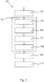
- Fig. 1 shows the schematic sequence of an embodiment of a method 101 for checking the preassembly of an example in FIG Fig. 4 shown cutting ring 1 on a pipe 2, i.e. to check whether the properties of the connection between cutting ring 1 and pipe 2 achieved by the pre-assembly process meet the requirements to achieve a tight cutting ring screw connection - not shown - and the necessary tightening forces for pipe 2.
- the method 101 is carried out with a device 3 which has at least one optical detection device 4 for detecting 102 image data in a detection area 5 (see Fig. 4 ).
- the method 101 comprises at least the method steps described below, namely firstly capturing 102 at least first image data of at least one tube 2 with a preassembled cutting ring 1 that is at least partially introduced into the detection region 5. An evaluation 103 of at least part of the first image data is then carried out in relation to one Position of the cutting ring 1 relative to the tube 2 and / or geometric changes in the tube 2 and / or geometric changes in the cutting ring 1.
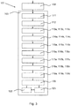
- Fig. 4 shows an embodiment of a device 3 for checking the preassembly of a cutting ring 1 on a pipe 2.
- the in Fig. 4 The device 3 shown has an illuminating device 6, which in this exemplary embodiment is a telecentric illuminating device 6.
- the illumination device 6 illuminates the tube 2 and the cutting ring 1 at least during the acquisition 102 of the first image data.
- the detection device 4 further comprises a telecentric lens 7 with which the tube 2 and the cutting ring 1 can be detected without distortion.
- the analysis 104 of the deformation 8 or the material throw-up in particular the degree - the extent - of the covering of a front cutting ring surface 9 of the cutting ring 1 by the Deformation 8 or the material throw determined.
- the degree of coverage of the front cutting ring surface 9 is determined at at least one point in the contour of the tube 2 and the cutting ring 1.
- the first image data preferably include an example in Fig. 5
- at least a part of the contour - at least at one point - of the cutting ring 1 and / or the pipe 2 in the silhouette 10 is then evaluated 103.
- the position of the cutting ring in relation to the pipe and / or geometric is preferred Changes in the tube, in particular a deformation of the tube, and / or geometric changes in the cutting ring are determined.
- Fig. 2 shows a schematic flow diagram of a further exemplary embodiment of a method 101 for checking the preassembly of a cutting ring 1 a tube 2.
- an evaluation 103 of at least part of the first image data takes place.
- 105 is found of a deformation 8 of the tube 2 generated by the cutting ring 1, in particular of a material throw-up, and the definition 106 of an example in FIG Fig.
- the deformation value in this exemplary embodiment Percentage of the degree of coverage of the front cutting ring surface 9 by the deformation 8 in the contour.
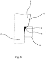
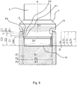
- the deformation value for Fig. 6 corresponds to 80%, which means covering the front cutting ring surface 9 in the contour by the deformation 8 to 80%.
- Fig. 3 shows a schematic sequence of a further exemplary embodiment of a method 101 according to the invention, which is carried out alternatively or in addition to the above-described methods or method steps.
- the first image data is evaluated 103, first determining 111 the position of an end edge 12 (see Fig. 5 and 8th ) he follows.
- at least one first edge 13 is determined 112 in the contour of the cutting ring 1, which here is the sealing surface of the cutting ring 1.
- measuring 113a a first, vertical distance C1 (see Fig. 8 ) between the end edge 12 of the tube 2 and a first point P1 on the first edge 13 of the cutting ring 1.
- 113b measures a second, vertical distance C2 between the end edge 12 of the tube 2 and a second point P2 on the first edge 13 of the cutting ring 1
- 113c measures a third, vertical distance C3 between the Front edge 12 of the tube 2 and a third point P3 on the first edge 13 of the cutting ring 1. All three points P1, P2 and P3 consequently lie on the sealing surface of the cutting ring 1.
- the first image data determine 114a a diameter B1 of the cutting ring 1 at point P1, determine 114b a diameter B2 of cutting ring 1 at point P2, and determine 114c the diameter B3 of cutting ring 1 at point P3.
- a calculation 116a of a radial distance A1 between the point P1 and the maximum cone diameter D1 of a screw connection piece for the cutting ring 1 is carried out.
- D1 is a cutting ring or pipe-specific constant and results in particular from Table 1.
- Bx is a placeholder for B1, B2 and B3 and Ax is a placeholder for A1, A2 and A3.
- a distance E1 is then calculated 117a taking into account the angle of inclination ⁇ of the first edge 13 to the longitudinal axis X of the pipe and the radial distance A1 using the tangent function
- a distance E2 is calculated 117b taking into account the angle of inclination ⁇ of the first edge 13 to the tube longitudinal axis X and the radial distance A2
- a calculation 117c of a distance E3 taking into account the angle of inclination ⁇ of the first edge 13 to the tube longitudinal axis X and the radial distance A3.
- Ex is a placeholder for E1, E2 and E3, Ax is a placeholder for A1, A2 and A3 and ⁇ is a placeholder for ⁇ , ⁇ and ⁇ .
- a penetration depth L1 is also calculated from the sum of the distances C1 and E1 and a calculation 118b of a penetration depth L2 from the sum of the distances C2 and E2 and a calculation 118c of a penetration depth L3 from the sum of the distances C3 and E3.
- Lx is a placeholder for L1, L2 and L3
- Cx is a placeholder for C1, C2 and C3
- Ex is a placeholder for E1, E2 and E3.
- a comparison 119a of the penetration depth L1 with a reference value or a tolerance range, a comparison 119b of the penetration depth L2 with a reference value or a tolerance range and a comparison 119c of the penetration depth L3 with a reference value or a tolerance range are then carried out.
- the determined penetration depth L M is then preferably compared with a reference value or a tolerance range, in particular the associated tolerance range (L Min - L Max ) from Table 1.
- M is the gap height
- L is a cutting ring-specific constant for the penetration depth
- L M is the averaged penetration depth determined on the specific test specimen. The smaller the gap height M, the better the position of the cutting ring 1 on the tube 2.
- Fig. 4 shows the schematic arrangement of an embodiment of the device 3 for checking the preassembly of a cutting ring 1 on a tube 2, having at least one detection device 4 with a telecentric lens 7 and an illumination device 6, which is aligned with the detection device 4 such that between the illumination device 6 and the detection device 4 has a detection area 5.
- the device 3 can consequently be used to record image data of a pipe 2 which can be arranged in the detection region 5 and has a pre-assembled cutting ring 1, the device 3 for evaluating at least part of the first image data in relation to a position of the cutting ring 1 relative to the pipe 2 and / or geometric changes in the pipe 2 and / or geometric changes of the cutting ring 1 is set up and formed.
- Fig. 5 shows an example of a shadow image 10 that has been acquired as part of the first image data.
- the contours of the cutting ring 1 and at least partially of the tube 2 can be seen from the silhouette 10.
- the deformation 8, here material throw-up, has formed on the front cutting ring surface 9 adjoining the sealing surface, here as the first edge 13, which is evaluated for the assessment of the preassembly at least at one point in the contour, as described.
- Fig. 6 shows a section of the Fig. 5 , in which the deformation 8 is highlighted in color - black.
- the evaluation area 11 shown as an example contains only the deformation 8.
- the evaluation area 11 was defined here on the basis of the front cutting ring edge 9 and the outer edge of the tube 2.
- the evaluation area 11 is evaluated on the basis of the number of image pixels of the deformation 8 and / or on the basis of the surface portions of the deformation 8.
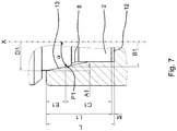
- Fig. 7 shows an embodiment of a tube 2 with pre-assembled cutting ring 1, introduced into a preassembly.
- a tube 2 with pre-assembled cutting ring 1 introduced into a preassembly.
- the dimensions D1 and B1 are only shown up to the pipe longitudinal axis X.
- Fig. 8 shows an embodiment of a tube 2 with pre-assembled cutting ring 1, introduced into a preassembly. All the previously described, calculated and measured values for all three points P1, P2 and P3 are shown.
- the value L M corresponds to the average penetration depth.
- the cone of the sealing surface of the cutting ring 1, which forms the edges 13 in the illustrated contour, usually has an angle of 24 ° between the edges 13 in the contour.
Landscapes
- Physics & Mathematics (AREA)
- General Physics & Mathematics (AREA)
- Engineering & Computer Science (AREA)
- General Engineering & Computer Science (AREA)
- Mechanical Engineering (AREA)
- Length Measuring Devices By Optical Means (AREA)
Claims (20)
- Procédé (101) de vérification du pré-montage d'une bague de coupe (1) sur un tube (2) avec un dispositif (3) comportant au moins un moyen de détection optique (4) destiné à détecter (102) des données d'image dans une zone de détection (5), le procédé comprenant au moins les étapes suivantes :- détecter (102) au moins des premières données d'image d'au moins un tube (2), introduit au moins partiellement dans la zone de détection (5), avec une bague de coupe pré-montée (1),- évaluer (103) au moins une partie des premières données d'image quant à une position de la bague de coupe (1) par rapport au tube (2) et/ou modifications géométriques du tube (2) et/ou modifications géométriques de la bague de coupe (1).
- Procédé (101) selon la revendication 1, caractérisé en ce que le dispositif (3) comprend un moyen d'éclairage (6), en particulier un moyen d'éclairage télécentrique (6), et en ce que, au moins pendant la détection (102) des premières données d'image, un éclairage au moins partiel du tube (2) et/ou de la bague de coupe (1) est effectué avec le moyen d'éclairage (6).
- Procédé (101) selon la revendication 1 ou 2, caractérisé en ce que le dispositif de détection (4) comporte un objectif télécentrique (7).
- Procédé (101) selon l'une des revendications 1 à 3, caractérisé en ce qu'au moins une déformation (8) du tube (2) générée par le pré-montage de la bague de coupe (1), en particulier une projection de matière du tube (2) générée par la bague de coupe (1), est analysée au moins partiellement (104) comme modification géométrique du tube (2).
- Procédé (101) selon la revendication 4, caractérisé en ce que, dans le cadre de l'analyse (104) de la déformation (8), en particulier de la projection de matière, le degré de recouvrement d'une surface avant (9) de la bague de coupe est déterminé par la déformation (8), en particulier la projection de matière.
- Procédé (101) selon l'une des revendication 1 à 5, caractérisé en ce que les premières données d'image contiennent une image d'ombre (10) d'au moins une partie du tube (2) et d'au moins une partie de la bague de coupe (1), et en ce que, pour effectuer l'évaluation (103), au moins une partie du contour de la bague de coupe (1) et/ou du tube (2) dans l'image d'ombre (10) est évaluée.
- Procédé (101) selon l'une des revendications 1 à 6,
caractérisé en ce que l'évaluation (103) des premières données d'image comprend les étapes de procédé suivantes :- trouver (105) une déformation (8) du tube (2), en particulier une projection de matière, générée par la bague de coupe (1),- définir (106) une zone d'évaluation (11) contenant la déformation (8), en particulier la projection de matière,- analyser (107) la zone d'évaluation (11), notamment en ce qui concerne la présence de pixels d'image,- déterminer (108) une valeur de déformation, en particulier une valeur de projection de matière. - Procédé (101) selon la revendication 7, caractérisé en ce qu'il comprend en outre les étapes suivantes :- comparer (109) la valeur de déformation, en particulier la valeur de projection de matière, à au moins une valeur de déformation mémorisée dans une base de données, en particulier une valeur de projection de matière, et/ou une gamme mémorisée de valeurs de déformation, en particulier de valeurs de projection de matière,- délivrer (110) un signal de qualité à l'aide d'un moyen de sortie.
- Procédé (101) selon l'une des revendications 1 à 8,
caractérisé en ce que l'évaluation (103) d'au moins les premières données d'image comprend les étapes de procédé suivantes :- déterminer (111) la position d'un bord frontal (12) du tube (2),- déterminer (112) au moins un premier bord (13), notamment dans le contour, de la bague de coupe (1),- mesurer (113a) une première distance (C1), notamment perpendiculaire, entre le bord frontal (12) du tube (2) et au moins un premier point (P1) sur le premier bord (13) de la bague de coupe (1). - Procédé (101) selon la revendication 9, caractérisé en ce que l'évaluation (103) comprend en outre les étapes de procédé suivantes,- mesurer (113b) une deuxième distance (C2), notamment perpendiculaire, entre le bord frontal (12) du tube (2) et au moins un deuxième point (P2) sur le premier bord (13) de la bague de coupe (1), notamment,- mesurer (113c) une troisième distance (C3), notamment perpendiculaire, entre le bord frontal (12) du tube (2) et au moins un troisième point (P3) sur le premier bord (13) de la bague de coupe (1).
- Procédé (101) selon la revendication 9 ou 10, caractérisé en ce que en particulier le premier bord (13) de la bague de coupe (1) contient une partie de la surface d'étanchéité de la bague de coupe (1), et en ce que l'évaluation (103) comprend en outre les étapes de procédé suivantes :- déterminer (114a) un diamètre (B1) de la bague de coupe (1) au point (P1),- déterminer (115a) l'angle d'inclinaison (α) du premier bord (13) au point (P1) par rapport à l'axe longitudinal du tube (X),- calculer (116a) une distance radiale (A1) entre le point (P1) et le diamètre de cône maximal (D1) d'un raccord de vissage de la bague de coupe (1),- calculer (117a) une distance (E1) avec prise en compte de l'angle d'inclinaison (α) du premier bord (13) par rapport à l'axe longitudinal du tube (X) et de la distance radiale (A1), en particulier avec la fonction tangente,- calculer (118a) une mesure de longueur (L1) à partir de la somme des distances (C1) et (E1),- comparer (119a) la mesure de longueur (L1) à une valeur de référence.
- Procédé (101) selon la revendication 11, caractérisé en ce que l'évaluation (103) comprend en outre les étapes de procédé suivantes :- déterminer (114b, 114c) les diamètres (B2) et (B3) de la bague de coupe (1) aux points (P1) et (P2),- déterminer (115b, 115c) les angles d'inclinaison (β) et (γ) du premier bord (13) aux points (P2) et (P3) par rapport à l'axe longitudinal du tube (X),- calculer (116b, 116c) les distances radiales (A2) et (A3) entre les points (P2) et (P3) et le diamètre de cône maximal (D1) d'un raccord de vissage de la bague de coupe (1),- calculer (117b, 117c) les distances (E2) et (E3) avec prise en compte des angles d'inclinaison (β) et (γ) du premier bord (13) par rapport à l'axe longitudinal du tube (X) et des distances radiales (A2) et (A3), en particulier avec la fonction tangente,- calculer (118b, 118c) les mesures de longueur (L2) et (L3) à partir de la somme des distances (C2) et (E2) et des distances (C3) et (E3),- calculer (120) une profondeur de pénétration moyenne (LM) à partir des mesures de longueur (L1, L2 et L3) .
- Procédé (101) selon la revendication 12, caractérisé en ce que la profondeur de pénétration moyenne (LM) est comparée (121) à au moins une valeur de référence.
- Procédé (101) selon la revendication 12 ou 13, caractérisé en ce qu'une hauteur d'espace (M) est calculée (122) avec la profondeur de pénétration moyenne (LM) et une profondeur de pénétration idéale (L) spécifique à la bague de coupe.
- Dispositif (3) de vérification du pré-montage d'une bague de coupe (1) sur un tube (2), le dispositif comprenant au moins un moyen de détection (4) et au moins un moyen d'éclairage (6), le moyen d'éclairage (6) étant orienté sur le moyen de détection (4) de manière à former une zone de détection (5) entre le moyen d'éclairage (6) et le moyen de détection (4) et à détecter, à l'aide du dispositif (3), des données d'image d'un tube (2) pouvant être disposé dans la zone de détection (5) et pourvu d'une bague de coupe pré-montée (1),
caractérisé en ce que le dispositif (3) comprend un moyen de traitement de données qui est conçu et adapté pour évaluer au moins une partie des premières données d'image quant à une position de la bague de coupe (1) par rapport au tube (2) et/ou une modification géométrique du tube (2) et/ou une modification géométriquement de la bague de coupe (1). - Dispositif (3) selon la revendication 15, caractérisé en ce que le dispositif (3) est conçu et adapté pour mettre en œuvre un procédé (101) selon les revendications 1 à 14.
- Dispositif (3) selon la revendication 15 ou 16, caractérisé en ce que le moyen de détection (4) est conçu comme une caméra ayant une résolution de 5 mégapixels, en particulier une précision de pixel comprise entre 3 µm et 6 µm.
- Dispositif (3) selon l'une des revendications 15 à 17,
caractérisé en ce que le moyen de détection (4) comporte un objectif télécentrique (7) et/ou le moyen d'éclairage (6) est conçu comme un moyen d'éclairage télécentrique (6). - Dispositif de pré-montage destiné au pré-montage d'une bague de coupe (1) sur un tube (2), le dispositif comprenant un raccord de pré-montage destiné à recevoir le tube (2) et la bague de coupe (1),
caractérisé en ce que le dispositif de pré-montage comprend un dispositif (3) selon l'une des revendications 15 à 18, en particulier relié mécaniquement et/ou électriquement à un dispositif (3) selon l'une des revendications 15 à 18. - Progiciel destiné à la mise en œuvre d'un procédé selon l'une des revendications 1 ou 4 à 14.
Priority Applications (1)
| Application Number | Priority Date | Filing Date | Title |
|---|---|---|---|
| PL18164103T PL3385665T3 (pl) | 2017-04-04 | 2018-03-27 | Sposób i urządzenie do sprawdzania montażu wstępnego pierścienia zacinającego na rurze |
Applications Claiming Priority (1)
| Application Number | Priority Date | Filing Date | Title |
|---|---|---|---|
| DE102017107173.3A DE102017107173A1 (de) | 2017-04-04 | 2017-04-04 | Verfahren und Vorrichtung zur Überprüfung der Vormontage eines Schneidrings auf einem Rohr |
Publications (3)
| Publication Number | Publication Date |
|---|---|
| EP3385665A1 EP3385665A1 (fr) | 2018-10-10 |
| EP3385665B1 EP3385665B1 (fr) | 2019-11-13 |
| EP3385665B9 true EP3385665B9 (fr) | 2020-04-29 |
Family
ID=61827536
Family Applications (1)
| Application Number | Title | Priority Date | Filing Date |
|---|---|---|---|
| EP18164103.6A Active EP3385665B9 (fr) | 2017-04-04 | 2018-03-27 | Procédé et dispositif de vérification du prémontage d'une bague de coupe sur un tube |
Country Status (5)
| Country | Link |
|---|---|
| EP (1) | EP3385665B9 (fr) |
| CN (1) | CN108759710B (fr) |
| DE (1) | DE102017107173A1 (fr) |
| ES (1) | ES2773579T3 (fr) |
| PL (1) | PL3385665T3 (fr) |
Family Cites Families (10)
| Publication number | Priority date | Publication date | Assignee | Title |
|---|---|---|---|---|
| DE3641816A1 (de) * | 1986-12-06 | 1988-06-16 | Robert Prof Dr Ing Massen | Verfahren und anordnung zur messung und/oder ueberwachung von eigenschaften von garnen und seilen |
| US6111601A (en) * | 1995-12-11 | 2000-08-29 | Adachi; Yoshi | Non-contacting laser gauge for qualifying screw fasteners and the like |
| DE19836071A1 (de) * | 1998-08-10 | 2000-02-17 | Schlafhorst & Co W | Verfahren zur Erkennung von Fadenresten auf Spinnkopshülsen |
| JP2000227316A (ja) * | 1999-02-04 | 2000-08-15 | Keyence Corp | 検査装置 |
| JP4573419B2 (ja) * | 2000-10-10 | 2010-11-04 | 株式会社キーエンス | 非接触型外形測定装置 |
| DE10140374A1 (de) * | 2001-08-28 | 2002-04-25 | Alfred Spitzley | Verfahren zur optoelektronischen Prüfung von Mantelflächen an zylindrischen Körpern auf Fehlerstellen mit Kamerasystemen |
| DE10359837A1 (de) * | 2003-12-19 | 2005-07-21 | Kamax-Werke Rudolf Kellermann Gmbh & Co. Kg | Verfahren und Vorrichtung zum Überprüfen eines Gewindes eines Verbindungselements auf Beschädigungen |
| DE102011003717A1 (de) * | 2011-02-07 | 2012-08-09 | Trumpf Werkzeugmaschinen Gmbh + Co. Kg | Vorrichtung und Verfahren zur Überwachung und insbesondere zur Regelung eines Laserschneidprozesses |
| DE102011082178A1 (de) * | 2011-09-06 | 2013-03-07 | Hauni Maschinenbau Ag | Optische Inspektion von stabförmigen Artikeln der Tabak verarbeitenden Industrie |
| DE102012102415B4 (de) * | 2012-03-21 | 2017-09-28 | Voss Fluid Gmbh | Montagesystem für Rohrverschraubungen mit Schneidring |
-
2017
- 2017-04-04 DE DE102017107173.3A patent/DE102017107173A1/de not_active Withdrawn
-
2018
- 2018-03-27 ES ES18164103T patent/ES2773579T3/es active Active
- 2018-03-27 PL PL18164103T patent/PL3385665T3/pl unknown
- 2018-03-27 EP EP18164103.6A patent/EP3385665B9/fr active Active
- 2018-04-03 CN CN201810291120.XA patent/CN108759710B/zh not_active Expired - Fee Related
Also Published As
| Publication number | Publication date |
|---|---|
| PL3385665T3 (pl) | 2020-05-18 |
| CN108759710A (zh) | 2018-11-06 |
| ES2773579T3 (es) | 2020-07-13 |
| DE102017107173A1 (de) | 2018-10-04 |
| CN108759710B (zh) | 2021-03-16 |
| EP3385665A1 (fr) | 2018-10-10 |
| EP3385665B1 (fr) | 2019-11-13 |
Similar Documents
| Publication | Publication Date | Title |
|---|---|---|
| DE3012559A1 (de) | Vorrichtung und verfahren zur automatischen untersuchung von produkten | |
| EP0938662B1 (fr) | Procede pour tester la fiabilite d'un appareil de controle, en particulier d'un systeme de controle de bouteilles vides | |
| DE3204086A1 (de) | Vorrichtung zur automatischen optischen beschaffenheitspruefung | |
| WO2015127950A1 (fr) | Procédé de détection de fissures dans les parois d'articles en verre creux | |
| DE60216623T3 (de) | Verfahren und anordnung in einem messsystem | |
| EP1677070B1 (fr) | Procédé et dispositif destinés à la détermination de la flexion d'un élément de liaison | |
| EP2851677B1 (fr) | Technique de balayage multilignes | |
| EP3108461B1 (fr) | Procédé d'examen d'un document de valeur et moyens d'exécution du procédé | |
| DE102023119420B4 (de) | Verfahren zur Erfassung von freien Enden von Steckspulen in einem Stator und Vorrichtung zur Erfassung von Hairpinpositionen mit einem Profilsensor | |
| EP3385665B9 (fr) | Procédé et dispositif de vérification du prémontage d'une bague de coupe sur un tube | |
| EP2636019A1 (fr) | Procédé et dispositif d'évaluation servant à déterminer la position d'une structure se trouvant dans un objet à examiner au moyen d'une tomographie aux rayons x assistée par ordinateur | |
| EP0475085B1 (fr) | Procédé de mesure pour déterminer l'élongation de rupture d'un échantillon sous tension pendant un essai de tension contrôlé par ordinateur | |
| DE102013006925A1 (de) | Vorrichtung und Verfahren zur Prüfung von Wertdokumenten, insbesondere Banknoten, sowie Wertdokumentbearbeitungssystem | |
| DE102008001174B4 (de) | Inspektionssystem und -verfahren für die optische Untersuchung von Objektoberflächen, insbesondere von Waferoberflächen | |
| WO1998021567A1 (fr) | Procede pour tester la fiabilite d'un appareil de controle, en particulier d'un systeme de controle d'une bouteille vide | |
| WO2005073698A1 (fr) | Procede de determination de la profondeur d'un defaut dans une bande de verre | |
| EP1897067B1 (fr) | Procede et dispositif de detection d'une monnaie par utilisation de son image estampee | |
| EP3561769B1 (fr) | Procédé de détection des discontinuités sur la surface d'un corps | |
| EP2833093A1 (fr) | Procédé et dispositif de mesure du centrage d'un conducteur dans une gaine isolante | |
| DE102019212022B4 (de) | Verfahren und Vorrichtung zum Feststellen eines Parallaxenproblems in Sensordaten zweier Sensoren | |
| EP1567991B1 (fr) | Procede et dispositif permettant de verifier des documents de valeur | |
| WO2022228840A1 (fr) | Procédé de mesure de sensibilité de détection d'un dispositif à rayons x | |
| DE102008049859B4 (de) | Verfahren und Prüfsystem zur optischen Prüfung einer Kontur eines Prüfobjekts | |
| DE102018126019A1 (de) | Verfahren und Vorrichtung zum Überprüfen von Spritzgussteilen, insbesondere Pipettenspitzen | |
| EP0597178A2 (fr) | Procédé et dispositif d'identification d'objets |
Legal Events
| Date | Code | Title | Description |
|---|---|---|---|
| PUAI | Public reference made under article 153(3) epc to a published international application that has entered the european phase |
Free format text: ORIGINAL CODE: 0009012 |
|
| STAA | Information on the status of an ep patent application or granted ep patent |
Free format text: STATUS: THE APPLICATION HAS BEEN PUBLISHED |
|
| AK | Designated contracting states |
Kind code of ref document: A1 Designated state(s): AL AT BE BG CH CY CZ DE DK EE ES FI FR GB GR HR HU IE IS IT LI LT LU LV MC MK MT NL NO PL PT RO RS SE SI SK SM TR |
|
| AX | Request for extension of the european patent |
Extension state: BA ME |
|
| STAA | Information on the status of an ep patent application or granted ep patent |
Free format text: STATUS: REQUEST FOR EXAMINATION WAS MADE |
|
| 17P | Request for examination filed |
Effective date: 20190403 |
|
| RBV | Designated contracting states (corrected) |
Designated state(s): AL AT BE BG CH CY CZ DE DK EE ES FI FR GB GR HR HU IE IS IT LI LT LU LV MC MK MT NL NO PL PT RO RS SE SI SK SM TR |
|
| GRAP | Despatch of communication of intention to grant a patent |
Free format text: ORIGINAL CODE: EPIDOSNIGR1 |
|
| STAA | Information on the status of an ep patent application or granted ep patent |
Free format text: STATUS: GRANT OF PATENT IS INTENDED |
|
| RIC1 | Information provided on ipc code assigned before grant |
Ipc: F16L 55/00 20060101ALI20190521BHEP Ipc: G01B 11/24 20060101AFI20190521BHEP |
|
| INTG | Intention to grant announced |
Effective date: 20190624 |
|
| GRAS | Grant fee paid |
Free format text: ORIGINAL CODE: EPIDOSNIGR3 |
|
| GRAJ | Information related to disapproval of communication of intention to grant by the applicant or resumption of examination proceedings by the epo deleted |
Free format text: ORIGINAL CODE: EPIDOSDIGR1 |
|
| GRAL | Information related to payment of fee for publishing/printing deleted |
Free format text: ORIGINAL CODE: EPIDOSDIGR3 |
|
| STAA | Information on the status of an ep patent application or granted ep patent |
Free format text: STATUS: REQUEST FOR EXAMINATION WAS MADE |
|
| GRAR | Information related to intention to grant a patent recorded |
Free format text: ORIGINAL CODE: EPIDOSNIGR71 |
|
| STAA | Information on the status of an ep patent application or granted ep patent |
Free format text: STATUS: GRANT OF PATENT IS INTENDED |
|
| GRAA | (expected) grant |
Free format text: ORIGINAL CODE: 0009210 |
|
| STAA | Information on the status of an ep patent application or granted ep patent |
Free format text: STATUS: THE PATENT HAS BEEN GRANTED |
|
| INTC | Intention to grant announced (deleted) | ||
| INTG | Intention to grant announced |
Effective date: 20191002 |
|
| AK | Designated contracting states |
Kind code of ref document: B1 Designated state(s): AL AT BE BG CH CY CZ DE DK EE ES FI FR GB GR HR HU IE IS IT LI LT LU LV MC MK MT NL NO PL PT RO RS SE SI SK SM TR |
|
| REG | Reference to a national code |
Ref country code: CH Ref legal event code: EP Ref country code: AT Ref legal event code: REF Ref document number: 1202132 Country of ref document: AT Kind code of ref document: T Effective date: 20191115 |
|
| REG | Reference to a national code |
Ref country code: DE Ref legal event code: R096 Ref document number: 502018000355 Country of ref document: DE |
|
| REG | Reference to a national code |
Ref country code: IE Ref legal event code: FG4D Free format text: LANGUAGE OF EP DOCUMENT: GERMAN |
|
| REG | Reference to a national code |
Ref country code: NL Ref legal event code: MP Effective date: 20191113 |
|
| REG | Reference to a national code |
Ref country code: LT Ref legal event code: MG4D |
|
| REG | Reference to a national code |
Ref country code: CH Ref legal event code: PK Free format text: BERICHTIGUNG B9 |
|
| PG25 | Lapsed in a contracting state [announced via postgrant information from national office to epo] |
Ref country code: SE Free format text: LAPSE BECAUSE OF FAILURE TO SUBMIT A TRANSLATION OF THE DESCRIPTION OR TO PAY THE FEE WITHIN THE PRESCRIBED TIME-LIMIT Effective date: 20191113 Ref country code: LV Free format text: LAPSE BECAUSE OF FAILURE TO SUBMIT A TRANSLATION OF THE DESCRIPTION OR TO PAY THE FEE WITHIN THE PRESCRIBED TIME-LIMIT Effective date: 20191113 Ref country code: NL Free format text: LAPSE BECAUSE OF FAILURE TO SUBMIT A TRANSLATION OF THE DESCRIPTION OR TO PAY THE FEE WITHIN THE PRESCRIBED TIME-LIMIT Effective date: 20191113 Ref country code: BG Free format text: LAPSE BECAUSE OF FAILURE TO SUBMIT A TRANSLATION OF THE DESCRIPTION OR TO PAY THE FEE WITHIN THE PRESCRIBED TIME-LIMIT Effective date: 20200213 Ref country code: FI Free format text: LAPSE BECAUSE OF FAILURE TO SUBMIT A TRANSLATION OF THE DESCRIPTION OR TO PAY THE FEE WITHIN THE PRESCRIBED TIME-LIMIT Effective date: 20191113 Ref country code: NO Free format text: LAPSE BECAUSE OF FAILURE TO SUBMIT A TRANSLATION OF THE DESCRIPTION OR TO PAY THE FEE WITHIN THE PRESCRIBED TIME-LIMIT Effective date: 20200213 Ref country code: PT Free format text: LAPSE BECAUSE OF FAILURE TO SUBMIT A TRANSLATION OF THE DESCRIPTION OR TO PAY THE FEE WITHIN THE PRESCRIBED TIME-LIMIT Effective date: 20200313 Ref country code: LT Free format text: LAPSE BECAUSE OF FAILURE TO SUBMIT A TRANSLATION OF THE DESCRIPTION OR TO PAY THE FEE WITHIN THE PRESCRIBED TIME-LIMIT Effective date: 20191113 Ref country code: GR Free format text: LAPSE BECAUSE OF FAILURE TO SUBMIT A TRANSLATION OF THE DESCRIPTION OR TO PAY THE FEE WITHIN THE PRESCRIBED TIME-LIMIT Effective date: 20200214 |
|
| PG25 | Lapsed in a contracting state [announced via postgrant information from national office to epo] |
Ref country code: HR Free format text: LAPSE BECAUSE OF FAILURE TO SUBMIT A TRANSLATION OF THE DESCRIPTION OR TO PAY THE FEE WITHIN THE PRESCRIBED TIME-LIMIT Effective date: 20191113 Ref country code: RS Free format text: LAPSE BECAUSE OF FAILURE TO SUBMIT A TRANSLATION OF THE DESCRIPTION OR TO PAY THE FEE WITHIN THE PRESCRIBED TIME-LIMIT Effective date: 20191113 Ref country code: IS Free format text: LAPSE BECAUSE OF FAILURE TO SUBMIT A TRANSLATION OF THE DESCRIPTION OR TO PAY THE FEE WITHIN THE PRESCRIBED TIME-LIMIT Effective date: 20200313 |
|
| PG25 | Lapsed in a contracting state [announced via postgrant information from national office to epo] |
Ref country code: AL Free format text: LAPSE BECAUSE OF FAILURE TO SUBMIT A TRANSLATION OF THE DESCRIPTION OR TO PAY THE FEE WITHIN THE PRESCRIBED TIME-LIMIT Effective date: 20191113 |
|
| REG | Reference to a national code |
Ref country code: ES Ref legal event code: FG2A Ref document number: 2773579 Country of ref document: ES Kind code of ref document: T3 Effective date: 20200713 |
|
| PG25 | Lapsed in a contracting state [announced via postgrant information from national office to epo] |
Ref country code: CZ Free format text: LAPSE BECAUSE OF FAILURE TO SUBMIT A TRANSLATION OF THE DESCRIPTION OR TO PAY THE FEE WITHIN THE PRESCRIBED TIME-LIMIT Effective date: 20191113 Ref country code: RO Free format text: LAPSE BECAUSE OF FAILURE TO SUBMIT A TRANSLATION OF THE DESCRIPTION OR TO PAY THE FEE WITHIN THE PRESCRIBED TIME-LIMIT Effective date: 20191113 Ref country code: DK Free format text: LAPSE BECAUSE OF FAILURE TO SUBMIT A TRANSLATION OF THE DESCRIPTION OR TO PAY THE FEE WITHIN THE PRESCRIBED TIME-LIMIT Effective date: 20191113 Ref country code: EE Free format text: LAPSE BECAUSE OF FAILURE TO SUBMIT A TRANSLATION OF THE DESCRIPTION OR TO PAY THE FEE WITHIN THE PRESCRIBED TIME-LIMIT Effective date: 20191113 |
|
| REG | Reference to a national code |
Ref country code: DE Ref legal event code: R097 Ref document number: 502018000355 Country of ref document: DE |
|
| PG25 | Lapsed in a contracting state [announced via postgrant information from national office to epo] |
Ref country code: SK Free format text: LAPSE BECAUSE OF FAILURE TO SUBMIT A TRANSLATION OF THE DESCRIPTION OR TO PAY THE FEE WITHIN THE PRESCRIBED TIME-LIMIT Effective date: 20191113 Ref country code: SM Free format text: LAPSE BECAUSE OF FAILURE TO SUBMIT A TRANSLATION OF THE DESCRIPTION OR TO PAY THE FEE WITHIN THE PRESCRIBED TIME-LIMIT Effective date: 20191113 |
|
| PLBE | No opposition filed within time limit |
Free format text: ORIGINAL CODE: 0009261 |
|
| STAA | Information on the status of an ep patent application or granted ep patent |
Free format text: STATUS: NO OPPOSITION FILED WITHIN TIME LIMIT |
|
| 26N | No opposition filed |
Effective date: 20200814 |
|
| PG25 | Lapsed in a contracting state [announced via postgrant information from national office to epo] |
Ref country code: MC Free format text: LAPSE BECAUSE OF FAILURE TO SUBMIT A TRANSLATION OF THE DESCRIPTION OR TO PAY THE FEE WITHIN THE PRESCRIBED TIME-LIMIT Effective date: 20191113 |
|
| PG25 | Lapsed in a contracting state [announced via postgrant information from national office to epo] |
Ref country code: SI Free format text: LAPSE BECAUSE OF FAILURE TO SUBMIT A TRANSLATION OF THE DESCRIPTION OR TO PAY THE FEE WITHIN THE PRESCRIBED TIME-LIMIT Effective date: 20191113 |
|
| REG | Reference to a national code |
Ref country code: BE Ref legal event code: MM Effective date: 20200331 |
|
| PG25 | Lapsed in a contracting state [announced via postgrant information from national office to epo] |
Ref country code: LU Free format text: LAPSE BECAUSE OF NON-PAYMENT OF DUE FEES Effective date: 20200327 |
|
| PG25 | Lapsed in a contracting state [announced via postgrant information from national office to epo] |
Ref country code: IE Free format text: LAPSE BECAUSE OF NON-PAYMENT OF DUE FEES Effective date: 20200327 |
|
| PG25 | Lapsed in a contracting state [announced via postgrant information from national office to epo] |
Ref country code: BE Free format text: LAPSE BECAUSE OF NON-PAYMENT OF DUE FEES Effective date: 20200331 |
|
| REG | Reference to a national code |
Ref country code: CH Ref legal event code: PL |
|
| PG25 | Lapsed in a contracting state [announced via postgrant information from national office to epo] |
Ref country code: CH Free format text: LAPSE BECAUSE OF NON-PAYMENT OF DUE FEES Effective date: 20210331 Ref country code: LI Free format text: LAPSE BECAUSE OF NON-PAYMENT OF DUE FEES Effective date: 20210331 |
|
| PG25 | Lapsed in a contracting state [announced via postgrant information from national office to epo] |
Ref country code: TR Free format text: LAPSE BECAUSE OF FAILURE TO SUBMIT A TRANSLATION OF THE DESCRIPTION OR TO PAY THE FEE WITHIN THE PRESCRIBED TIME-LIMIT Effective date: 20191113 Ref country code: MT Free format text: LAPSE BECAUSE OF FAILURE TO SUBMIT A TRANSLATION OF THE DESCRIPTION OR TO PAY THE FEE WITHIN THE PRESCRIBED TIME-LIMIT Effective date: 20191113 Ref country code: CY Free format text: LAPSE BECAUSE OF FAILURE TO SUBMIT A TRANSLATION OF THE DESCRIPTION OR TO PAY THE FEE WITHIN THE PRESCRIBED TIME-LIMIT Effective date: 20191113 |
|
| PG25 | Lapsed in a contracting state [announced via postgrant information from national office to epo] |
Ref country code: MK Free format text: LAPSE BECAUSE OF FAILURE TO SUBMIT A TRANSLATION OF THE DESCRIPTION OR TO PAY THE FEE WITHIN THE PRESCRIBED TIME-LIMIT Effective date: 20191113 |
|
| GBPC | Gb: european patent ceased through non-payment of renewal fee |
Effective date: 20220327 |
|
| PG25 | Lapsed in a contracting state [announced via postgrant information from national office to epo] |
Ref country code: GB Free format text: LAPSE BECAUSE OF NON-PAYMENT OF DUE FEES Effective date: 20220327 |
|
| P01 | Opt-out of the competence of the unified patent court (upc) registered |
Effective date: 20230601 |
|
| REG | Reference to a national code |
Ref country code: AT Ref legal event code: MM01 Ref document number: 1202132 Country of ref document: AT Kind code of ref document: T Effective date: 20230327 |
|
| PGFP | Annual fee paid to national office [announced via postgrant information from national office to epo] |
Ref country code: PL Payment date: 20240226 Year of fee payment: 7 Ref country code: IT Payment date: 20240227 Year of fee payment: 7 Ref country code: FR Payment date: 20240228 Year of fee payment: 7 |
|
| PGFP | Annual fee paid to national office [announced via postgrant information from national office to epo] |
Ref country code: DE Payment date: 20240523 Year of fee payment: 7 |
|
| PGFP | Annual fee paid to national office [announced via postgrant information from national office to epo] |
Ref country code: ES Payment date: 20240422 Year of fee payment: 7 |
|
| PG25 | Lapsed in a contracting state [announced via postgrant information from national office to epo] |
Ref country code: AT Free format text: LAPSE BECAUSE OF NON-PAYMENT OF DUE FEES Effective date: 20230327 |
|
| PG25 | Lapsed in a contracting state [announced via postgrant information from national office to epo] |
Ref country code: AT Free format text: LAPSE BECAUSE OF NON-PAYMENT OF DUE FEES Effective date: 20230327 |
|
| REG | Reference to a national code |
Ref country code: DE Ref legal event code: R119 Ref document number: 502018000355 Country of ref document: DE |
|
| PG25 | Lapsed in a contracting state [announced via postgrant information from national office to epo] |
Ref country code: DE Free format text: LAPSE BECAUSE OF NON-PAYMENT OF DUE FEES Effective date: 20251001 |
|
| PG25 | Lapsed in a contracting state [announced via postgrant information from national office to epo] |
Ref country code: FR Free format text: LAPSE BECAUSE OF NON-PAYMENT OF DUE FEES Effective date: 20250331 Ref country code: IT Free format text: LAPSE BECAUSE OF NON-PAYMENT OF DUE FEES Effective date: 20250327 |
|
| PGFP | Annual fee paid to national office [announced via postgrant information from national office to epo] |
Ref country code: AT Payment date: 20260410 Year of fee payment: 5 |