EP3385671A1 - Navigationssystem mit verwendung von giergeschwindigkeitseinschränkung während intertialer koppelnavigation - Google Patents
Navigationssystem mit verwendung von giergeschwindigkeitseinschränkung während intertialer koppelnavigation Download PDFInfo
- Publication number
- EP3385671A1 EP3385671A1 EP18150408.5A EP18150408A EP3385671A1 EP 3385671 A1 EP3385671 A1 EP 3385671A1 EP 18150408 A EP18150408 A EP 18150408A EP 3385671 A1 EP3385671 A1 EP 3385671A1
- Authority
- EP
- European Patent Office
- Prior art keywords
- update
- mechanization
- ins
- yaw rate
- gnss
- Prior art date
- Legal status (The legal status is an assumption and is not a legal conclusion. Google has not performed a legal analysis and makes no representation as to the accuracy of the status listed.)
- Granted
Links
Images



Classifications
-
- G—PHYSICS
- G01—MEASURING; TESTING
- G01C—MEASURING DISTANCES, LEVELS OR BEARINGS; SURVEYING; NAVIGATION; GYROSCOPIC INSTRUMENTS; PHOTOGRAMMETRY OR VIDEOGRAMMETRY
- G01C21/00—Navigation; Navigational instruments not provided for in groups G01C1/00 - G01C19/00
- G01C21/10—Navigation; Navigational instruments not provided for in groups G01C1/00 - G01C19/00 by using measurements of speed or acceleration
- G01C21/12—Navigation; Navigational instruments not provided for in groups G01C1/00 - G01C19/00 by using measurements of speed or acceleration executed aboard the object being navigated; Dead reckoning
- G01C21/16—Navigation; Navigational instruments not provided for in groups G01C1/00 - G01C19/00 by using measurements of speed or acceleration executed aboard the object being navigated; Dead reckoning by integrating acceleration or speed, i.e. inertial navigation
- G01C21/18—Stabilised platforms, e.g. by gyroscope
-
- G—PHYSICS
- G01—MEASURING; TESTING
- G01C—MEASURING DISTANCES, LEVELS OR BEARINGS; SURVEYING; NAVIGATION; GYROSCOPIC INSTRUMENTS; PHOTOGRAMMETRY OR VIDEOGRAMMETRY
- G01C21/00—Navigation; Navigational instruments not provided for in groups G01C1/00 - G01C19/00
- G01C21/10—Navigation; Navigational instruments not provided for in groups G01C1/00 - G01C19/00 by using measurements of speed or acceleration
- G01C21/12—Navigation; Navigational instruments not provided for in groups G01C1/00 - G01C19/00 by using measurements of speed or acceleration executed aboard the object being navigated; Dead reckoning
- G01C21/16—Navigation; Navigational instruments not provided for in groups G01C1/00 - G01C19/00 by using measurements of speed or acceleration executed aboard the object being navigated; Dead reckoning by integrating acceleration or speed, i.e. inertial navigation
- G01C21/165—Navigation; Navigational instruments not provided for in groups G01C1/00 - G01C19/00 by using measurements of speed or acceleration executed aboard the object being navigated; Dead reckoning by integrating acceleration or speed, i.e. inertial navigation combined with non-inertial navigation instruments
-
- G—PHYSICS
- G01—MEASURING; TESTING
- G01C—MEASURING DISTANCES, LEVELS OR BEARINGS; SURVEYING; NAVIGATION; GYROSCOPIC INSTRUMENTS; PHOTOGRAMMETRY OR VIDEOGRAMMETRY
- G01C25/00—Manufacturing, calibrating, cleaning, or repairing instruments or devices referred to in the other groups of this subclass
- G01C25/005—Manufacturing, calibrating, cleaning, or repairing instruments or devices referred to in the other groups of this subclass initial alignment, calibration or starting-up of inertial devices
-
- G—PHYSICS
- G01—MEASURING; TESTING
- G01S—RADIO DIRECTION-FINDING; RADIO NAVIGATION; DETERMINING DISTANCE OR VELOCITY BY USE OF RADIO WAVES; LOCATING OR PRESENCE-DETECTING BY USE OF THE REFLECTION OR RERADIATION OF RADIO WAVES; ANALOGOUS ARRANGEMENTS USING OTHER WAVES
- G01S19/00—Satellite radio beacon positioning systems; Determining position, velocity or attitude using signals transmitted by such systems
- G01S19/38—Determining a navigation solution using signals transmitted by a satellite radio beacon positioning system
- G01S19/39—Determining a navigation solution using signals transmitted by a satellite radio beacon positioning system the satellite radio beacon positioning system transmitting time-stamped messages, e.g. GPS [Global Positioning System], GLONASS [Global Orbiting Navigation Satellite System] or GALILEO
- G01S19/42—Determining position
- G01S19/45—Determining position by combining measurements of signals from the satellite radio beacon positioning system with a supplementary measurement
- G01S19/47—Determining position by combining measurements of signals from the satellite radio beacon positioning system with a supplementary measurement the supplementary measurement being an inertial measurement, e.g. tightly coupled inertial
Definitions
- the invention relates to GNSS/INS navigation systems and, in particular, to GNSS/INS navigation systems that utilize a yaw rate constraint during dead reckoning.
- GNSS/INS navigation systems such as the systems described in United States Patents 6,721,657 and 7,193,559 , which are assigned to a common assignee and incorporated herein by reference, may be used in vehicles to aid in navigation and also in the control of the vehicles.
- the GNSS/INS navigation systems work well to provide accurate up-to-date INS-based position, velocity and attitude information to a vehicle navigation and control system that, in turn, provides navigation information to a user directly or via a map.
- the vehicle navigation and control system may utilize the navigation information to control the vehicle.
- a GNSS subsystem of the GNSS/INS navigation system receives GNSS satellite signals and, operating in a known manner, processes the GNSS satellite signals to produce GNSS measurements and observables and determine GNSS positions, velocities, times and associated covariance corresponding to GNSS measurement times.
- An INS subsystem includes an inertial measurement unit (IMU) that reads data from orthogonally positioned sensors, i.e., accelerometers and gyroscopes, and produces IMU measurements.
- IMU inertial measurement unit
- the accelerometers and gyroscopes have associated biases that, if not corrected for, introduce drift errors into the IMU measurements.
- the INS subsystem uses the GNSS position, covariance and, as appropriate, GNSS measurements and observables in an INS filter to aid in the correction of the drift errors in the INS measurements.
- the inertial subsystem then utilizes inertial measurements to provide INS-based position, velocity and attitude in between the GNSS measurement times, that is, during measurement intervals.
- the GNSS/INS navigation system operates in a known manner to provide uninterrupted navigation information, even in environments in which sufficient numbers of GNSS satellites are not continuously in view.
- the GNSS/INS navigation system utilizes the inertial measurements to continue to provide updated INS-based position, velocity and attitude during the GNSS outage.
- the operations of the GNSS/INS navigation system without GNSS updates are referred to as dead reckoning.
- the gyroscopes in the IMU tend to have very large biases and can drift quickly when left un-aided by the GNSS information. Accordingly, without the GNSS updates, the accuracy of the INS-based position, velocity and attitude is adversely affected. In particular, uncorrected gyroscope measurements result in determinations of inaccurate vehicle heading which is one of the major sources of error in the calculations of INS-based position, velocity and attitude.
- the GNSS/INS navigation systems work well when the GNSS outages are relatively short, such as, for example, when the systems momentarily loose lock on the GNSS satellite signals or fewer than a required number of GNSS satellites are in view because of obstructions in the area or traveling through tunnels and so forth, and aiding is again available to control the drift errors after a single or a small number of measurement intervals.
- the outage of GNSS information lasts for much longer periods of time due, for example, to the GNSS antenna falling off of the vehicle or the GNSS antenna otherwise becoming disabled, or interference such as jamming in the area
- the GNSS/INS navigation system must continue to operate with inertial sensors that have unchecked drift errors over many measurement intervals.
- the increasingly larger drift errors adversely affect the accuracy of the operations of the system and, in particular, result in increasing inaccuracies in the determination of vehicle heading. This in turn leads to greater errors in the calculation of the INS-based position, velocity and attitude.
- One way to aid in the determination of the vehicle heading during dead reckoning is to equip the vehicle with specialized instrumentation, such as, for example, a magnetometer and/or a turning angle feedback instrument, to provide additional information for use in the calculation.
- specialized instrumentation adds to the cost and complexity of the vehicle, and thus, such instrumentation is not typically included. Accordingly, the drift errors of the INS sensors and the associated inaccuracies in the calculation of position, velocity and attitude may result in the vehicle navigation and control systems determining that the vehicle has turned, when the vehicle is actually proceeding in the same direction. Alternatively, the control system may erroneously determine that the vehicle has not turned when, in fact, the vehicle has turned. Either inaccuracy adversely affects the operations of vehicle navigation and/or vehicle control by the navigation/control system.
- An improved GNSS/INS navigation system or INS navigation system includes an INS filter that, during dead reckoning operations, utilizes relative yaw rate measurements, that is, the measurements of rotation about a z-axis of a vehicle, made by one or more INS sensors, to constrain the z-axis drift errors of the one or more INS sensors.
- the system includes a yaw rate constraint subsystem that accumulates relative yaw measurements over mechanization update intervals to produce dead reckoning mechanization update values, accumulates the values over a turn rate accumulation period that consists of one or more mechanization update intervals, and determines a corresponding yaw rate.
- the yaw rate constraint subsystem determines if the yaw rate exceeds a turn rate threshold that is based on an expected intentional turn angle in the applicable environment, i.e., land, sea or air.
- the subsystem directs the INS filter to perform a zero yaw rate update.
- the zero yaw rate update uses the rotation in the relative yaw measurements over the previous mechanization update interval to correct for the z-axis drift errors of the one or more INS sensors that contribute to the relative yaw measurement and sets the z-axis drift errors to zero for the mechanization update interval. If the yaw rate exceeds the turn rate threshold, the system does not perform a zero yaw rate update and the sensor drift error remains unchecked for the mechanization update interval.
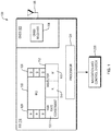
- a GNSS/INS navigation system 100 for use with a driver controlled or driverless/autonomous vehicle includes a GNSS subsystem 102 and an INS subsystem 110.
- the GNSS subsystem 102 includes a GNSS receiver 104 that operates in a known manner to process GNSS satellite signals that are received by a GNSS antenna 106 and produce GNSS raw measurements, such as pseudoranges, carrier phases, and Doppler velocities; GNSS position, velocity and time, and position covariance; and, as appropriate, GNSS observables.
- the GNSS raw measurements, GNSS position, velocity and time, and the position covariance and the GNSS observables are hereinafter referred to collectively as "GNSS measurement information.”
- the INS subsystem 110 includes an inertial measurement unit (IMU) 118 that reads data from orthogonally positioned INS sensors, which consist of accelerometers 109 and gyroscopes 108, and produces INS measurements.
- IMU inertial measurement unit
- An INS filter 112 processes the GNSS measurement information, when available during a navigation mode, and the INS measurements and produces INS-based position, velocity and attitude. If any distance measurement indicators (DMI), such as speedometers, and so forth (not shown), are included on the vehicle, the INS subsystem includes the DMImeasurements in the calculations in a known manner.
- DMI distance measurement indicators
- the INS subsystem 110 further includes a yaw rate constraint subsystem 120 that, as discussed below, operates with the INS filter 112 when the system 100 is operating in a dead reckoning mode.
- the INS-based position, velocity and/or attitude produced by the INS subsystem 110 are provided to a navigation and control system 200, which operates in a known manner to produce navigation information that is provided to the user directly or via a map display.
- the navigation and control system 200 operates in a known manner to utilize the navigation information to control operations of the vehicle.
- the GNSS subsystem 102 and the INS subsystem 110 operate under the control of a processor 124.
- the processor 124 operates in a known manner to control the time tagging of the GNSS measurement information and the INS measurements.
- the processor further operates to control the operations of the GNSS subsystem to produce the GNSS measurement information and the INS subsystem to produce the INS measurements, as well as the operations of the INS filter to produce the INS-based position, velocity and/or attitude, which are provided to the vehicle navigation and control system 200.
- the operations of the GNSS subsystem and the INS subsystem are discussed without specific reference to the processor 124.
- the GNSS/INS system 100 operates in two modes, a navigation mode in which GNSS measurement information is available from the GNSS subsystem 102 and the dead reckoning mode in which the GNSS measurement information is not available.
- the dead reckoning mode the yaw rate constraint subsystem 120 operates with the INS filter 112 to selectively provide aid to correct for z-axis drift errors of the one or more IMU gyroscopes that contribute to the measurement of rotation about the z-axis of the vehicle.
- the operations of the yaw rate constraint subsystem are discussed in more detail below.
- the GNSS/INS system 100 has been initialized in a known manner to operate in the navigation mode.
- the gyroscopes measuring rotation about the X, Y and Z axes have been identified and various associated matrices for the INS filter have been established, including matrices for a Kalman filter process 114.
- the INS subsystem 110 uses the GNSS measurement information in an update to the Kalman filter process 114, which provides updated error states to a mechanization process 116 in order to correct for the drift errors of the respective IMU sensors 108 and 109.
- the mechanization process 116 uses the updated error states and the IMU measurements to determine the INS-based position, velocity and/or attitude over the intervals between the Kalman filter process updates.
- the intervals between the Kalman filter updates are hereinafter referred to as "mechanization update intervals.”
- the INS subsystem filter 112 performs two main processes, the mechanization of the raw gyroscope and accelerometer measurements into a trajectory, that is, a time series of position, velocity and attitude, and the correction of that trajectory with updates estimated by the GNSS/INS integration process, which is the Kalman filter process 114.
- the Kalman filter that is used for the INS integration contains state variables representing the errors of the system being modeled, which are position, velocity, attitude, IMU sensor errors, and optionally an offset vector (or lever arm) from the IMU 118 to the GNSS antenna 106.
- the mechanization occurs at the rate of the IMU data (typically delta velocity and angular increments) at a relatively high rate, usually 100 Hz or higher.
- the Kalman filter runs at a lower rate, for example at 1 Hz, such that errors in the INS trajectory accumulate to become clearly observable when compared to the update information provided by the GNSS subsystem 102. Further, the lower rate tends to keep the updates sufficiently separated in time to eliminate, or at least mitigate, time correlated errors on the update measurements.
- the Kalman filter is propagated between update measurements.
- the values for the states and their variances are propagated forward in time based on how they are known to behave as defined in the transition matrix.
- the states can be observed and the observations are then utilized to update the gain and covariance matrices P and a state vector x.
- the Kalman filter is based on a state space model that defines the relationships between the states with a first order differential equation.
- x ⁇ Fx + Gw
- F is the dynamics matrix that defines a differential equation relating the states to their time derivative
- w is the noise associated with the process
- G is a matrix that acts as a shaping filter to distribute the noise across the states.
- the Kalman filter is propagated between update measurements.
- the values for the states and their variances are propagated forward in time based on how they are known to behave as defined in the transition matrix.
- the update measurement is an external measure of the state values, while the Kalman filter propagation provides the assumed state values based on the model.
- the variable ⁇ k used in the update is the absolute measurement made, while z k is the value computed by the observation model and the current state estimates x k .
- the propagation step can happen as often as the user would like updated state and variance estimates based on the state space model.
- the update step can happen whenever an external aiding measurement is available.
- the mechanization process is providing the full system values (i.e. position, velocity, and attitude) at a high rate (i.e. >100Hz) allowing the errors described in the Kalman filter's state vector to accumulate. The errors are thus well observed in the update measurement, which happens at a lower rate (i.e. 1 Hz).
- the estimated state vector is used to correct the mechanized trajectory (and update IMU sensor error estimates), and then set to zero, because once the error estimates have been applied to the trajectory, all known error has been removed from the system.
- the gain matrix K is formed as a combination of the design matrix H, the state variance matrix P, and the update measurement variance matrix R.
- the design matrix defines how the states are combined to create the observation equation, and this determines the observability of the states through the update.
- the state and measurement variance matrices control how much a state can be corrected by the update, that is, they control the overall gains for each state. For example, if the measurement has a much larger variance than the state variance, even if the design matrix indicates that the measurement has strong observability, the correction to the states will be minimized, via a small gain value, because the filter knowledge of the state is stronger than the measurement.
- the extended Kalman filter state estimates begin to converge. This convergence is indicated in the state variance matrix P, as the matrix is updated with the gain matrix and design matrix of the update measurements.
- the GNSS subsystem 102 When signals from a sufficient number of GNSS satellite signals are available, the GNSS subsystem 102 operates in a known manner to provide GNSS measurement information to the INS subsystem at the start of a mechanization update interval.
- the mechanization update intervals are timed to the updating of the GNSS measurement information, which occurs at 1 second intervals.
- the INS subsystem 110 operating in a known manner, utilizes the GNSS measurement information to correct for the drift of the INS sensors by updating the error states.
- the INS subsystem also utilizes the IMU measurements and produces the INS-based position, velocity and attitude that are provided to the vehicle navigation and control system 200 over the mechanization update interval.
- the vehicle navigation and control system then operates in a known manner to utilize the INS-based position, velocity and attitude information to produce updated navigation information which may be provided to a user either directly or via a map display.
- the navigation information may also be used to control the vehicle, such as, for example, to providing steering corrections or steering the vehicle entirely during autonomous driving sessions.
- the GNSS/INS system 100 continues to operate in the navigation mode as long as updated GNSS measurement information is available. When updated GNSS measurement information is not available, the GNSS/INS system 100 operates in the dead reckoning mode in which the INS measurements are utilized without the aiding of the GNSS measurement information that corrects for the IMU sensor biases, or drift errors, in the IMU measurements.
- the yaw rate constraint subsystem 120 operates in both the navigation mode and the dead reckoning mode to accumulate the relative yaw measurements, that is, the measurements of one or more IMU gyroscopes 108 along the z-axis of the vehicle, over the mechanization update intervals.
- the z-axis gyroscope measurements accumulated over a mechanization update are hereinafter referred to as a "dead reckoning mechanization update value.”
- the yaw rate constraint subsystem further accumulates the dead reckoning mechanization update values over turn rate accumulation periods, which as discussed below may be one or more mechanization update intervals long. For each turn rate accumulation period, the yaw rate constraint subsystem determines a corresponding yaw rate, which is utilized when the system 100 is operating in the dead reckoning mode, as discussed in more detail below.
- the yaw rate constraint subsystem 120 operates with the INS filter 112, to selectively aid the correction of drift errors of the one or more IMU gyroscopes that make the measurements associated with relative yaw, that is, the measurements of rotation about the z-axis of the vehicle.
- the yaw rate constraint subsystem 120 accumulates dead reckoning mechanization update values over a turn rate accumulation period to determine a corresponding yaw rate. Based on the yaw rate, the yaw rate constraint subsystem determines if the vehicle is turning, and thus, whether or not the INS subsystem 110 should perform a zero yaw rate update to correct for the z-axis drift errors of the IMU gyroscopes that contributed to the relative yaw measurements, as discussed in more detail below.
- the turn rate accumulation period is selected to be relatively short, and is selected as a trade-off between providing aiding to correct for the drift errors often and confidence in the determination of whether or not the vehicle is turning.
- the INS sensor readings are taken at the IMU rate and the turn rate accumulation period is selected to be one or more mechanization update intervals long. If the IMU gyroscopes are low cost gyroscopes that tend to have noisy measurements, the turn rate accumulation period may be selected to be multiple mechanization update intervals long, to ensure confidence in the determination of whether or not the vehicle is turning.
- the turn rate accumulation period may also, or in addition, be selected to be longer based on the vehicle and/or the environment in which the vehicle travels.
- a longer turn rate accumulation period may be selected for a system 100 operating in a tractor as opposed to operating in a luxury car.
- the vehicle is a luxury car and the IMU uses low cost gyroscopes, and the turn rate accumulation period is selected to be 5 mechanization update intervals long.
- the turn rate accumulation period is 5 seconds long.
- the yaw rate constraint subsystem 120 determines if the yaw rate over the turn rate accumulation period is below a turn threshold that is set at or slightly above an intentional turn rate determined for the environment in which the vehicle is traveling. In the example, the vehicle is traveling on land and the intentional turn rate turn is determined to be greater than 0.5 degrees/second, and the turn threshold is set at 0.75 degrees/second. If the calculated yaw rate does not exceed the turn threshold, the yaw rate constraint subsystem directs the INS filter to perform a zero yaw rate update, to correct for drift errors in the z-axis measurements of the IMU gyroscopes. If the calculated yaw rate exceeds the turn rate the INS filter is not instructed to perform the zero rate update.
- a turn threshold that is set at or slightly above an intentional turn rate determined for the environment in which the vehicle is traveling. In the example, the vehicle is traveling on land and the intentional turn rate turn is determined to be greater than 0.5 degrees/second, and the turn threshold is set at
- the yaw rate constraint subsystem 120 determines that the yaw rate does not exceed the turn threshold, and thus, that the vehicle is not turning, the yaw rate constraint subsystem directs the INS filter 112 to perform the zero yaw rate update.
- the INS filter 112 uses the dead reckoning mechanization update value for the previous mechanization update interval to correct for the z-axis drift errors of the IMU z-axis gyroscopes, and then sets the z-axis drift errors to zero to start the mechanization interval.
- the rotation matrix included in the design matrix H is defined by the mechanization frame of the INS filter. In the example, the mechanization frame of the INS filter is the ECEF frame.
- the operations of the yaw rate constraint subsystem 120 are not adversely affected by the speed of the vehicle. Rather, the yaw rate constraint subsystem operates efficiently to determine if a zero yaw rate update should be performed to correct for the IMU gyroscope z-axis drift errors, whether the vehicle is stopped, moving slowly or speeding along. Further, if the level of noise in the relative yaw measurements is high, the INS filter may appropriately weight the measurements that are utilized to perform the zero yaw rate update, to minimize correcting for the excess noise in the measurements.
- the yaw rate constraint subsystem 120 determines if the yaw rate that is associated with the current turn rate accumulation period, that is, the accumulation period that ends at the end of the previous mechanization update interval, falls below the turn rate threshold. If so, the yaw rate constraint subsystem directs the INS filter to perform a zero yaw rate update using the dead reckoning mechanization update value from the previous mechanization update interval.
- the INS filter performs the zero yaw rate update, which updates the error state of the IMU gyroscopes that contribute to the relative yaw measurements to correct for the z-axis drift error.
- the INS filter then sets the z-axis drift errors of the IMU gyroscopes to zero for the start of the mechanization update interval.
- the subsystem does not direct the INS filter 110 to perform a zero yaw rate update.
- the z-axis drift errors remain unchecked for the start of the mechanization update interval. Since the yaw rate constraint subsystem determines, at the start of each mechanization update interval, if a zero yaw rate update should be performed, the z-axis drift errors are again corrected for once the vehicle completes its turn. Thus, the z-axis drift errors remain unchecked for one or a small number of mechanization update intervals.
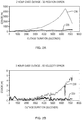
- the error rates are plotted against time for the calculations of INS-based position, velocity and attitude, or azimuth, during a 2 hour GNSS outage, i.e., during a 2 hour period of operating in the dead reckoning mode.
- the error rates for a navigation system that operates with the yaw rate constraint subsystem 120 are represented in the respective charts by line 220 and the error rates for the navigation system that operates without the yaw rate constraint subsystem are represented in the respective charts by line 230.
- the error rates associated with the navigation system that utilizes the yaw rate constraint subsystem are near zero degrees over the 2 hour outage, while the error rates associated with the navigation system that does not utilize the yaw rate constraint subsystem grow over much if not all of the 2 hour GNSS outage.
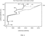
- a solid line 300 illustrates the route traveled by a vehicle over a highway for approximately 4 hours, which includes a 2 hour GNSS outage that begins at a time that coincides with point 340, continues while the vehicle turns around at a time that coincides with point 350, and ends as the vehicle returns along the same highway at a time that coincides with point 360, that is, GNSS again becomes available at this time.
- the route depicted by line 300 is plotted as distance travelled in meters from the start location.against axes of latitude in meters and longitude in meters.
- the starred line 320 represents a route determined by a GNSS/INS navigation system with DMI and the yaw rate constraint subsystem 120, which operates as discussed above when the system is in the dead reckoning mode during the 2 hour GNSS outage.
- the dotted line 330 represents the route determined by a GNSS/INS navigation system with DMI and without the yaw rate constraint subsystem.
- the route 320 determined by the system with DMI and the yaw rate constraint subsystem closely follows the actual route 300 throughout the entire journey, including during the two hour GNSS outage.
- the route 330 determined without the aiding of the yaw rate subsystem exhibits increasing position inaccuracies during the 2 hour GNSS outage.
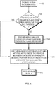
- Figs. 4 and 5 are flow charts of the operations of the system to Fig. 1 .
- the GNSS/INS system 100 operates in the navigation mode if GNSS measurement information is available.
- the GNSS/INS system utilizes the GNSS measurement information to update the INS filter 112 and correct for the drift errors of the IMU sensors 108 and 109 and determine the INS-based position, velocity and attitude for the start of the mechanization update interval.
- Step 406 uses the IMU measurements to calculate INS-based position, velocity and attitude, over the mechanization update interval.
- Step 408 uses the IMU measurements to calculate INS-based position, velocity and attitude, over the mechanization update interval.
- Step 410 the system then goes to Step 400 at the start of the next mechanization update interval.
- the GNSS/INS system operates in the dead reckoning mode. Steps 400, 402, 414 and 502.
- the yaw rate constraint subsystem 120 determines if the yaw rate for the current turn rate accumulation period, which ends at the end of the previous mechanization update interval, exceeds the turn rate threshold. Step 504.
- the INS filter performs a zero yaw rate update using the dead reckoning mechanization update value for the previous mechanization update interval, that is, the accumulation of the relative yaw measurements over the previous mechanization update interval, to update the error states and correct for the z-axis drift errors of the IMU gyroscopes contributing to the relative yaw measurements.
- the system also sets the z-axis drift errors of the contributing IMU gyroscopes to zero.
- the system uses the INS-based position, velocity and attitude at the end of the previous mechanization update interval for the start of the current mechanization update interval. Step 508.
- Step 510 the system goes to Step 408 of Fig. 4 .
- the system thus calculates the INS-based position, velocity and attitude over the mechanization update interval based on the IMU measurements.
- Step 410 the system updates the calculated yaw rate for the current turn rate accumulation period based on the dead reckoning mechanization update value calculated for the current mechanization update interval.
- Step 412 the system returns to Step 400 at the start of a next mechanization update interval and determines if the system continues to operate in the dead reckoning mode or instead operates in the navigation mode, and so forth.
- Step 512 The system in, Step 508, uses the INS-based position, velocity and attitude at the end of the previous mechanization update interval for the start of the current mechanization update interval.
- Step 510 the system goes to Step 408 of Fig. 4 .
- the system thus calculates the INS-based position, velocity and attitude, over the measurement interval, based on IMU measurements.
- Step 410 the system also accumulates relative yaw measurements over the mechanization update interval to produce the dead reckoning mechanization update value and the system updates the yaw rate for the current turn rate accumulation period, and in Step 412 the system goes to Step 400 and repeats the various steps at the start of the next mechanization update interval.
- an improved inertial navigation system 600 that operates as a dead reckoning device includes an IMU 110 with orthogonally positioned accelerometers and gyroscopes 108 and 109, and an INS filter 612, which operates using IMU measurements in the same manner as the INS filter 112 of Fig.1 .
- the system further includes the yaw rate constraint system 120 that operates as described above, such that the z-axis drift errors of the IMU gyroscopes that contribute to the relative yaw measurements, which are measurements of rotation about a z-axis of the vehicle (not shown), are constrained using relative yaw measurements taken when the vehicle is not turning.
- the inertial navigation system 600 may also utilize information provided by DMI sensors (not shown), in the manner discussed above.
- the system 600 performs Steps 504, 506, 508, 510, 512 of Fig, 5 and steps 408 and 410 of Fig, 4 before returning to Step 504 at the start of the next mechanization update interval.
- the GNSS/INS navigation system 100 and inertial navigation system 600 each utilize the yaw rate constraint subsystem 120 during dead reckoning operations to provide aiding to correct for the z-axis drift errors of the one or more IMU gyroscopes that contribute to the relative yaw measurements, as long as the system determines that the vehicle is not then turning. Accordingly, during the dead reckoning operations, the system determines vehicle heading and, in turn, INS-based position, velocity and attitude, with increased accuracy over systems that do not utilize the yaw rate constrain subsystem.
- the GNSS/INS system 100 is depicted as consisting of various interconnected subsystems, the system may be configured with more or fewer subsystems, and the system processor 124 may consist of two or more processors that operate respectively with one or more of the subsystems.
- the yaw rate constraint subsystem may operate to begin accumulating the relative yaw measurements at the start of the dead reckoning mode, such that there is a delay equal to the length of the turn rate accumulation period before the yaw rate constraint subsystem determines if zero yaw updates should be performed. Additionally, the yaw rate constraint system may, but need not, calculate the yaw rate while the system is operating in the navigation mode.
Landscapes
- Engineering & Computer Science (AREA)
- Radar, Positioning & Navigation (AREA)
- Remote Sensing (AREA)
- Physics & Mathematics (AREA)
- General Physics & Mathematics (AREA)
- Automation & Control Theory (AREA)
- Computer Networks & Wireless Communication (AREA)
- Manufacturing & Machinery (AREA)
- Navigation (AREA)
- Position Fixing By Use Of Radio Waves (AREA)
Applications Claiming Priority (1)
| Application Number | Priority Date | Filing Date | Title |
|---|---|---|---|
| US15/479,875 US10533856B2 (en) | 2017-04-05 | 2017-04-05 | Navigation system utilizing yaw rate constraint during inertial dead reckoning |
Publications (2)
| Publication Number | Publication Date |
|---|---|
| EP3385671A1 true EP3385671A1 (de) | 2018-10-10 |
| EP3385671B1 EP3385671B1 (de) | 2025-04-09 |
Family
ID=60935729
Family Applications (1)
| Application Number | Title | Priority Date | Filing Date |
|---|---|---|---|
| EP18150408.5A Active EP3385671B1 (de) | 2017-04-05 | 2018-01-05 | Navigationssystem mit verwendung von giergeschwindigkeitseinschränkung während intertialer koppelnavigation |
Country Status (3)
| Country | Link |
|---|---|
| US (2) | US10533856B2 (de) |
| EP (1) | EP3385671B1 (de) |
| CA (1) | CA2986501C (de) |
Families Citing this family (26)
| Publication number | Priority date | Publication date | Assignee | Title |
|---|---|---|---|---|
| EP3497405B1 (de) * | 2016-08-09 | 2022-06-15 | Nauto, Inc. | System und verfahren zur präzisionsortung und kartierung |
| US10753752B2 (en) * | 2018-07-26 | 2020-08-25 | Trimble Inc. | Vehicle manual guidance systems with steering wheel angle sensors and road wheel angle sensors |
| JP7336752B2 (ja) * | 2018-12-28 | 2023-09-01 | パナソニックIpマネジメント株式会社 | 測位装置及び移動体 |
| CN109974697B (zh) * | 2019-03-21 | 2022-07-26 | 中国船舶重工集团公司第七0七研究所 | 一种基于惯性系统的高精度测绘方法 |
| CN110106755B (zh) * | 2019-04-04 | 2020-11-03 | 武汉大学 | 利用姿态重构铁轨几何形态的高铁轨道不平顺性检测方法 |
| CN112577512B (zh) * | 2019-09-27 | 2024-12-10 | 北京魔门塔科技有限公司 | 一种基于轮速融合的状态量误差确定方法及车载终端 |
| WO2021096812A1 (en) * | 2019-11-12 | 2021-05-20 | Viasat, Inc. | Yaw drift compensation for pointing an antenna |
| US11592295B2 (en) * | 2019-11-26 | 2023-02-28 | Invensense, Inc. | System and method for position correction |
| CN111060133B (zh) * | 2019-12-04 | 2020-10-20 | 南京航空航天大学 | 一种用于城市复杂环境的组合导航完好性监测方法 |
| US20210231439A1 (en) * | 2020-01-24 | 2021-07-29 | Aptiv Technologies Limited | Vehicle heading information based on single satellite detection |
| CN113447960B (zh) * | 2020-03-26 | 2022-06-24 | 千寻位置网络有限公司 | 基于gnss/mems组合车载导航系统的误差标定方法及系统 |
| WO2021222712A1 (en) | 2020-05-01 | 2021-11-04 | Kinze Manufacturing, Inc. | Connected planter data sharing playthrough |
| US12196557B2 (en) * | 2020-06-17 | 2025-01-14 | Novatel Inc. | System and method for dead reckoning for marine positioning applications |
| US12535323B2 (en) * | 2020-08-10 | 2026-01-27 | Qualcomm Incorporated | Updating vehicle attitude for extended dead reckoning accuracy |
| US11671133B2 (en) | 2020-10-16 | 2023-06-06 | Deere & Company | Adaptive narrowband and wideband interference rejection for satellite navigation receiver |
| US11742883B2 (en) | 2020-10-16 | 2023-08-29 | Deere & Company | Adaptive narrowband interference rejection for satellite navigation receiver |
| US11764862B2 (en) | 2020-10-16 | 2023-09-19 | Deere & Company | Adaptive narrowband interference rejection for satellite navigation receiver |
| CN112729730B (zh) * | 2020-12-23 | 2025-03-07 | 中国矿业大学 | 一体化gnss/加速度计与mems-imu融合监测桥梁挠度的方法 |
| CN114413934B (zh) * | 2022-01-20 | 2024-01-26 | 北京经纬恒润科技股份有限公司 | 一种车辆定位系统校正方法和装置 |
| US12153143B2 (en) | 2022-02-18 | 2024-11-26 | Deere & Company | Multi-constellation, multi-frequency GNSS system for interference mitigation |
| US12066551B2 (en) | 2022-02-18 | 2024-08-20 | Deere & Company | Multi-constellation, multi-frequency GNSS system for interference mitigation |
| CN114739393B (zh) * | 2022-03-09 | 2025-01-24 | 中国电子科技集团公司第五十四研究所 | 基于里程计辅助的ins/gnss车载组合导航方法 |
| JP7781738B2 (ja) | 2022-12-28 | 2025-12-08 | 株式会社クボタ | 作業車両、作業車両の制御システムおよび制御方法 |
| CN119738849A (zh) * | 2023-09-22 | 2025-04-01 | 广东高驰运动科技有限公司 | 一种移动轨迹生成方法、电子设备及可读存储介质 |
| CN118980372B (zh) * | 2024-08-07 | 2025-04-15 | 交通运输部科学研究院 | 基于驾驶行为和惯性导航的gnss短时失效下的车辆定位方法、车辆定位装置和系统 |
| CN121300384B (zh) * | 2025-12-11 | 2026-04-07 | 厦门金龙电控科技有限公司 | 低速无人车轨迹跟踪与运动控制方法及系统 |
Citations (6)
| Publication number | Priority date | Publication date | Assignee | Title |
|---|---|---|---|---|
| US6401036B1 (en) * | 2000-10-03 | 2002-06-04 | Motorola, Inc. | Heading and position error-correction method and apparatus for vehicle navigation systems |
| US6721657B2 (en) | 2001-06-04 | 2004-04-13 | Novatel, Inc. | Inertial GPS navigation system |
| US7193559B2 (en) | 2003-01-21 | 2007-03-20 | Novatel, Inc. | Inertial GPS navigation system with modified kalman filter |
| US20090254276A1 (en) * | 2008-04-08 | 2009-10-08 | Ensco, Inc. | Method and computer-readable storage medium with instructions for processing data in an internal navigation system |
| US20140203971A1 (en) * | 2013-01-22 | 2014-07-24 | Ensco, Inc. | System and method for tracking and locating a person, animal, or machine |
| US20140324291A1 (en) * | 2003-03-20 | 2014-10-30 | Agjunction Llc | Gnss and optical guidance and machine control |
Family Cites Families (39)
| Publication number | Priority date | Publication date | Assignee | Title |
|---|---|---|---|---|
| US5525998A (en) | 1994-08-01 | 1996-06-11 | Motorola, Inc. | Odometer assisted GPS navigation method |
| JPH08136569A (ja) * | 1994-11-09 | 1996-05-31 | Toyota Motor Corp | 検出装置 |
| US6308134B1 (en) * | 1996-12-27 | 2001-10-23 | Magellan Dis, Inc. | Vehicle navigation system and method using multiple axes accelerometer |
| US6246960B1 (en) * | 1998-11-06 | 2001-06-12 | Ching-Fang Lin | Enhanced integrated positioning method and system thereof for vehicle |
| US6327523B2 (en) * | 1999-01-21 | 2001-12-04 | Hughes Electronics Corporation | Overhead system of inclined eccentric geosynchronous orbitting satellites |
| US6285927B1 (en) * | 1999-05-26 | 2001-09-04 | Hughes Electronics Corporation | Spacecraft attitude determination system and method |
| US6442385B1 (en) * | 1999-11-04 | 2002-08-27 | Xm Satellite Radio, Inc. | Method and apparatus for selectively operating satellites in tundra orbits to reduce receiver buffering requirements for time diversity signals |
| JP3428539B2 (ja) * | 1999-12-10 | 2003-07-22 | 日本電気株式会社 | 人工衛星の姿勢角センサ較正装置 |
| US6285928B1 (en) * | 2000-01-06 | 2001-09-04 | Space Systems/Loral, Inc. | Onboard attitude control using reaction wheels |
| US6441776B1 (en) * | 2000-01-07 | 2002-08-27 | Hughes Electronics Corporation | Method and apparatus for spacecraft payload pointing registration |
| US6381520B1 (en) * | 2000-07-10 | 2002-04-30 | Space Systems/Loral, Inc. | Sun seeking solar array control system and method |
| US6356815B1 (en) * | 2000-08-25 | 2002-03-12 | Hughes Electronics Corporation | Stellar attitude-control systems and methods with weighted measurement-noise covariance matrices |
| US6481672B1 (en) * | 2001-01-18 | 2002-11-19 | Lockheed Martin Corporation | Gimbaled thruster control system |
| US6732977B1 (en) * | 2002-02-11 | 2004-05-11 | Lockheed Martin Corporation | System for on-orbit correction of spacecraft payload pointing errors |
| US6702234B1 (en) * | 2002-03-29 | 2004-03-09 | Lockheed Martin Corporation | Fault tolerant attitude control system for zero momentum spacecraft |
| DE102005033237B4 (de) * | 2005-07-15 | 2007-09-20 | Siemens Ag | Verfahren zur Bestimmung und Korrektur von Fehlorientierungen und Offsets der Sensoren einer Inertial Measurement Unit in einem Landfahrzeug |
| US7835826B1 (en) * | 2005-12-13 | 2010-11-16 | Lockheed Martin Corporation | Attitude determination system for yaw-steering spacecraft |
| US20080228329A1 (en) * | 2007-03-13 | 2008-09-18 | Honeywell International Inc. | Methods and systems for friction detection and slippage control |
| US8019542B2 (en) | 2007-04-16 | 2011-09-13 | Honeywell International Inc. | Heading stabilization for aided inertial navigation systems |
| US20110087450A1 (en) * | 2009-04-03 | 2011-04-14 | University Of Michigan | Heading Error Removal System for Tracking Devices |
| US8311740B2 (en) * | 2010-01-28 | 2012-11-13 | CSR Technology Holdings Inc. | Use of accelerometer only data to improve GNSS performance |
| IL207536A (en) * | 2010-08-11 | 2016-11-30 | Israel Aerospace Ind Ltd | A system and method for measuring aviation platform angular orientation |
| JP6094026B2 (ja) * | 2011-03-02 | 2017-03-15 | セイコーエプソン株式会社 | 姿勢判定方法、位置算出方法及び姿勢判定装置 |
| US9784582B2 (en) * | 2011-09-14 | 2017-10-10 | Invensense, Inc. | Method and apparatus for navigation with nonlinear models |
| US20130179119A1 (en) * | 2011-12-21 | 2013-07-11 | Robotics Paradigm Systems, LLC | Data collection and point cloud generation system and method |
| US8433514B1 (en) * | 2012-05-17 | 2013-04-30 | Trimble Navigation, Limited | Navigation sensor mounting-angle calibration |
| US9057615B2 (en) * | 2012-10-26 | 2015-06-16 | Texas Instruments Incorporated | Systems and methods for navigating using corrected yaw bias values |
| CN103063216B (zh) * | 2013-01-06 | 2015-08-12 | 南京航空航天大学 | 一种基于星像坐标建模的惯性与天文组合导航方法 |
| US20140372027A1 (en) * | 2013-06-14 | 2014-12-18 | Hangzhou Haicun Information Technology Co. Ltd. | Music-Based Positioning Aided By Dead Reckoning |
| US9383209B2 (en) * | 2013-09-23 | 2016-07-05 | Texas Instruments Incorporated | Undocking and re-docking mobile device inertial measurement unit from vehicle |
| US9964648B2 (en) * | 2015-06-16 | 2018-05-08 | Insero LLC | Guidiance system and method based on dead reckoning positioning and heading augmented by GNSS and predictive path selection |
| US9983301B2 (en) * | 2015-10-02 | 2018-05-29 | Delphi Technologies, Inc. | Automated vehicle radar system to determine yaw-rate of a target vehicle |
| US10386203B1 (en) * | 2015-11-05 | 2019-08-20 | Invensense, Inc. | Systems and methods for gyroscope calibration |
| CN105371845A (zh) * | 2015-12-17 | 2016-03-02 | 安徽寰智信息科技股份有限公司 | 一种惯性追踪模块 |
| CN105389014A (zh) * | 2015-12-17 | 2016-03-09 | 安徽寰智信息科技股份有限公司 | 一种三维人机交互系统 |
| US10055651B2 (en) * | 2016-03-08 | 2018-08-21 | Magna Electronics Inc. | Vehicle vision system with enhanced lane tracking |
| KR101718654B1 (ko) * | 2016-03-18 | 2017-03-22 | 주식회사 풍산 | L자형 비틀림 구조를 가지는 발사체용 가속도센서 |
| US9791279B1 (en) * | 2016-06-30 | 2017-10-17 | U-Blox Ag | System for and method of determining angular position of a vehicle |
| US10129691B2 (en) * | 2016-10-14 | 2018-11-13 | OneMarket Network LLC | Systems and methods to determine a location of a mobile device |
-
2017
- 2017-04-05 US US15/479,875 patent/US10533856B2/en active Active
- 2017-11-23 CA CA2986501A patent/CA2986501C/en active Active
-
2018
- 2018-01-05 EP EP18150408.5A patent/EP3385671B1/de active Active
-
2019
- 2019-05-21 US US16/418,575 patent/US11105633B2/en active Active
Patent Citations (6)
| Publication number | Priority date | Publication date | Assignee | Title |
|---|---|---|---|---|
| US6401036B1 (en) * | 2000-10-03 | 2002-06-04 | Motorola, Inc. | Heading and position error-correction method and apparatus for vehicle navigation systems |
| US6721657B2 (en) | 2001-06-04 | 2004-04-13 | Novatel, Inc. | Inertial GPS navigation system |
| US7193559B2 (en) | 2003-01-21 | 2007-03-20 | Novatel, Inc. | Inertial GPS navigation system with modified kalman filter |
| US20140324291A1 (en) * | 2003-03-20 | 2014-10-30 | Agjunction Llc | Gnss and optical guidance and machine control |
| US20090254276A1 (en) * | 2008-04-08 | 2009-10-08 | Ensco, Inc. | Method and computer-readable storage medium with instructions for processing data in an internal navigation system |
| US20140203971A1 (en) * | 2013-01-22 | 2014-07-24 | Ensco, Inc. | System and method for tracking and locating a person, animal, or machine |
Also Published As
| Publication number | Publication date |
|---|---|
| CA2986501A1 (en) | 2018-10-05 |
| US20180292212A1 (en) | 2018-10-11 |
| US11105633B2 (en) | 2021-08-31 |
| CA2986501C (en) | 2023-10-17 |
| US10533856B2 (en) | 2020-01-14 |
| EP3385671B1 (de) | 2025-04-09 |
| US20200025572A1 (en) | 2020-01-23 |
Similar Documents
| Publication | Publication Date | Title |
|---|---|---|
| US11105633B2 (en) | Navigation system utilizing yaw rate constraint during inertial dead reckoning | |
| EP3408688B1 (de) | Gnss und trägheitsnavigationssystem mit relativen gierwerten als beobachtbare kenngrösse für ein ins-filter | |
| US8024119B2 (en) | Systems and methods for gyrocompass alignment using dynamically calibrated sensor data and an iterated extended kalman filter within a navigation system | |
| EP2045577B1 (de) | Positionierungsvorrichtung und navigationssystem | |
| US6826478B2 (en) | Inertial navigation system for mobile objects with constraints | |
| AU774089B2 (en) | Terrain navigation apparatus for a legged animal traversing terrain | |
| US8560234B2 (en) | System and method of navigation based on state estimation using a stepped filter | |
| US20030036847A1 (en) | Position and heading error-correction method and apparatus for vehicle navigation systems | |
| EP1837627A2 (de) | Verfahren und System zur Integration eines wiederholten und erweiterten Kalman-Filters in ein Navigationssystem | |
| US20070271037A1 (en) | Systems and methods for improved inertial navigation | |
| EP1903308A2 (de) | Systeme und Verfahren für eine Übergangsmatrix im Hybridzustand | |
| JP2008232869A (ja) | Gps複合航法装置 | |
| US12202531B2 (en) | Method for calculating an instantaneous velocity vector of a rail vehicle and corresponding system | |
| EP3312634B1 (de) | Positionierungsvorrichtung | |
| EP3848672B1 (de) | Integriertes trägheitsgravitationsanomalienavigationssystem | |
| AU2015213260B2 (en) | Machine positioning system having alignment error detection | |
| Zhu et al. | Improved Gaussian process regression-based method to bridge GPS outages in INS/GPS integrated navigation systems | |
| US11085773B2 (en) | Angular velocity sensor correction device and method for correcting output signal from angular velocity sensor, and direction estimation device and method for estimating direction by correcting output signal from angular velocity sensor | |
| RU2539131C1 (ru) | Бесплатформенная интегрированная навигационная система средней точности для мобильного наземного объекта | |
| CN115597594B (zh) | 基于里程修正因子的卫惯组合导航方法和系统 | |
| US20250389537A1 (en) | Computer-implemented methods for attitude determination of an aircraft for navigation | |
| Rogers | Integrated DR/DGPS using low cost gyro and speed sensor |
Legal Events
| Date | Code | Title | Description |
|---|---|---|---|
| PUAI | Public reference made under article 153(3) epc to a published international application that has entered the european phase |
Free format text: ORIGINAL CODE: 0009012 |
|
| STAA | Information on the status of an ep patent application or granted ep patent |
Free format text: STATUS: THE APPLICATION HAS BEEN PUBLISHED |
|
| AK | Designated contracting states |
Kind code of ref document: A1 Designated state(s): AL AT BE BG CH CY CZ DE DK EE ES FI FR GB GR HR HU IE IS IT LI LT LU LV MC MK MT NL NO PL PT RO RS SE SI SK SM TR |
|
| AX | Request for extension of the european patent |
Extension state: BA ME |
|
| STAA | Information on the status of an ep patent application or granted ep patent |
Free format text: STATUS: REQUEST FOR EXAMINATION WAS MADE |
|
| 17P | Request for examination filed |
Effective date: 20190405 |
|
| RBV | Designated contracting states (corrected) |
Designated state(s): AL AT BE BG CH CY CZ DE DK EE ES FI FR GB GR HR HU IE IS IT LI LT LU LV MC MK MT NL NO PL PT RO RS SE SI SK SM TR |
|
| STAA | Information on the status of an ep patent application or granted ep patent |
Free format text: STATUS: EXAMINATION IS IN PROGRESS |
|
| 17Q | First examination report despatched |
Effective date: 20220208 |
|
| GRAP | Despatch of communication of intention to grant a patent |
Free format text: ORIGINAL CODE: EPIDOSNIGR1 |
|
| STAA | Information on the status of an ep patent application or granted ep patent |
Free format text: STATUS: GRANT OF PATENT IS INTENDED |
|
| INTG | Intention to grant announced |
Effective date: 20241202 |
|
| GRAS | Grant fee paid |
Free format text: ORIGINAL CODE: EPIDOSNIGR3 |
|
| GRAA | (expected) grant |
Free format text: ORIGINAL CODE: 0009210 |
|
| STAA | Information on the status of an ep patent application or granted ep patent |
Free format text: STATUS: THE PATENT HAS BEEN GRANTED |
|
| AK | Designated contracting states |
Kind code of ref document: B1 Designated state(s): AL AT BE BG CH CY CZ DE DK EE ES FI FR GB GR HR HU IE IS IT LI LT LU LV MC MK MT NL NO PL PT RO RS SE SI SK SM TR |
|
| RAP3 | Party data changed (applicant data changed or rights of an application transferred) |
Owner name: NOVATEL, INC. |
|
| REG | Reference to a national code |
Ref country code: GB Ref legal event code: FG4D |
|
| REG | Reference to a national code |
Ref country code: CH Ref legal event code: EP |
|
| REG | Reference to a national code |
Ref country code: DE Ref legal event code: R096 Ref document number: 602018080892 Country of ref document: DE |
|
| REG | Reference to a national code |
Ref country code: IE Ref legal event code: FG4D |
|
| REG | Reference to a national code |
Ref country code: NL Ref legal event code: MP Effective date: 20250409 |
|
| PG25 | Lapsed in a contracting state [announced via postgrant information from national office to epo] |
Ref country code: NL Free format text: LAPSE BECAUSE OF FAILURE TO SUBMIT A TRANSLATION OF THE DESCRIPTION OR TO PAY THE FEE WITHIN THE PRESCRIBED TIME-LIMIT Effective date: 20250409 |
|
| REG | Reference to a national code |
Ref country code: AT Ref legal event code: MK05 Ref document number: 1783865 Country of ref document: AT Kind code of ref document: T Effective date: 20250409 |
|
| PG25 | Lapsed in a contracting state [announced via postgrant information from national office to epo] |
Ref country code: PT Free format text: LAPSE BECAUSE OF FAILURE TO SUBMIT A TRANSLATION OF THE DESCRIPTION OR TO PAY THE FEE WITHIN THE PRESCRIBED TIME-LIMIT Effective date: 20250811 Ref country code: ES Free format text: LAPSE BECAUSE OF FAILURE TO SUBMIT A TRANSLATION OF THE DESCRIPTION OR TO PAY THE FEE WITHIN THE PRESCRIBED TIME-LIMIT Effective date: 20250409 Ref country code: FI Free format text: LAPSE BECAUSE OF FAILURE TO SUBMIT A TRANSLATION OF THE DESCRIPTION OR TO PAY THE FEE WITHIN THE PRESCRIBED TIME-LIMIT Effective date: 20250409 |
|
| REG | Reference to a national code |
Ref country code: LT Ref legal event code: MG9D |
|
| PG25 | Lapsed in a contracting state [announced via postgrant information from national office to epo] |
Ref country code: NO Free format text: LAPSE BECAUSE OF FAILURE TO SUBMIT A TRANSLATION OF THE DESCRIPTION OR TO PAY THE FEE WITHIN THE PRESCRIBED TIME-LIMIT Effective date: 20250709 Ref country code: GR Free format text: LAPSE BECAUSE OF FAILURE TO SUBMIT A TRANSLATION OF THE DESCRIPTION OR TO PAY THE FEE WITHIN THE PRESCRIBED TIME-LIMIT Effective date: 20250710 |
|
| PG25 | Lapsed in a contracting state [announced via postgrant information from national office to epo] |
Ref country code: PL Free format text: LAPSE BECAUSE OF FAILURE TO SUBMIT A TRANSLATION OF THE DESCRIPTION OR TO PAY THE FEE WITHIN THE PRESCRIBED TIME-LIMIT Effective date: 20250409 |
|
| PG25 | Lapsed in a contracting state [announced via postgrant information from national office to epo] |
Ref country code: BG Free format text: LAPSE BECAUSE OF FAILURE TO SUBMIT A TRANSLATION OF THE DESCRIPTION OR TO PAY THE FEE WITHIN THE PRESCRIBED TIME-LIMIT Effective date: 20250409 |
|
| PG25 | Lapsed in a contracting state [announced via postgrant information from national office to epo] |
Ref country code: HR Free format text: LAPSE BECAUSE OF FAILURE TO SUBMIT A TRANSLATION OF THE DESCRIPTION OR TO PAY THE FEE WITHIN THE PRESCRIBED TIME-LIMIT Effective date: 20250409 |
|
| PG25 | Lapsed in a contracting state [announced via postgrant information from national office to epo] |
Ref country code: AT Free format text: LAPSE BECAUSE OF FAILURE TO SUBMIT A TRANSLATION OF THE DESCRIPTION OR TO PAY THE FEE WITHIN THE PRESCRIBED TIME-LIMIT Effective date: 20250409 |
|
| PG25 | Lapsed in a contracting state [announced via postgrant information from national office to epo] |
Ref country code: RS Free format text: LAPSE BECAUSE OF FAILURE TO SUBMIT A TRANSLATION OF THE DESCRIPTION OR TO PAY THE FEE WITHIN THE PRESCRIBED TIME-LIMIT Effective date: 20250709 |
|
| PG25 | Lapsed in a contracting state [announced via postgrant information from national office to epo] |
Ref country code: IS Free format text: LAPSE BECAUSE OF FAILURE TO SUBMIT A TRANSLATION OF THE DESCRIPTION OR TO PAY THE FEE WITHIN THE PRESCRIBED TIME-LIMIT Effective date: 20250809 |
|
| PG25 | Lapsed in a contracting state [announced via postgrant information from national office to epo] |
Ref country code: LV Free format text: LAPSE BECAUSE OF FAILURE TO SUBMIT A TRANSLATION OF THE DESCRIPTION OR TO PAY THE FEE WITHIN THE PRESCRIBED TIME-LIMIT Effective date: 20250409 |
|
| REG | Reference to a national code |
Ref country code: DE Ref legal event code: R097 Ref document number: 602018080892 Country of ref document: DE |
|
| PG25 | Lapsed in a contracting state [announced via postgrant information from national office to epo] |
Ref country code: SM Free format text: LAPSE BECAUSE OF FAILURE TO SUBMIT A TRANSLATION OF THE DESCRIPTION OR TO PAY THE FEE WITHIN THE PRESCRIBED TIME-LIMIT Effective date: 20250409 Ref country code: DK Free format text: LAPSE BECAUSE OF FAILURE TO SUBMIT A TRANSLATION OF THE DESCRIPTION OR TO PAY THE FEE WITHIN THE PRESCRIBED TIME-LIMIT Effective date: 20250409 |
|
| PG25 | Lapsed in a contracting state [announced via postgrant information from national office to epo] |
Ref country code: CZ Free format text: LAPSE BECAUSE OF FAILURE TO SUBMIT A TRANSLATION OF THE DESCRIPTION OR TO PAY THE FEE WITHIN THE PRESCRIBED TIME-LIMIT Effective date: 20250409 |
|
| PG25 | Lapsed in a contracting state [announced via postgrant information from national office to epo] |
Ref country code: EE Free format text: LAPSE BECAUSE OF FAILURE TO SUBMIT A TRANSLATION OF THE DESCRIPTION OR TO PAY THE FEE WITHIN THE PRESCRIBED TIME-LIMIT Effective date: 20250409 |
|
| PG25 | Lapsed in a contracting state [announced via postgrant information from national office to epo] |
Ref country code: SK Free format text: LAPSE BECAUSE OF FAILURE TO SUBMIT A TRANSLATION OF THE DESCRIPTION OR TO PAY THE FEE WITHIN THE PRESCRIBED TIME-LIMIT Effective date: 20250409 Ref country code: RO Free format text: LAPSE BECAUSE OF FAILURE TO SUBMIT A TRANSLATION OF THE DESCRIPTION OR TO PAY THE FEE WITHIN THE PRESCRIBED TIME-LIMIT Effective date: 20250409 |
|
| PG25 | Lapsed in a contracting state [announced via postgrant information from national office to epo] |
Ref country code: IT Free format text: LAPSE BECAUSE OF FAILURE TO SUBMIT A TRANSLATION OF THE DESCRIPTION OR TO PAY THE FEE WITHIN THE PRESCRIBED TIME-LIMIT Effective date: 20250409 |
|
| REG | Reference to a national code |
Ref country code: CH Ref legal event code: U11 Free format text: ST27 STATUS EVENT CODE: U-0-0-U10-U11 (AS PROVIDED BY THE NATIONAL OFFICE) Effective date: 20260201 |
|
| PLBE | No opposition filed within time limit |
Free format text: ORIGINAL CODE: 0009261 |
|
| STAA | Information on the status of an ep patent application or granted ep patent |
Free format text: STATUS: NO OPPOSITION FILED WITHIN TIME LIMIT |
|
| REG | Reference to a national code |
Ref country code: CH Ref legal event code: L10 Free format text: ST27 STATUS EVENT CODE: U-0-0-L10-L00 (AS PROVIDED BY THE NATIONAL OFFICE) Effective date: 20260218 |
|
| 26N | No opposition filed |
Effective date: 20260112 |
|
| PGFP | Annual fee paid to national office [announced via postgrant information from national office to epo] |
Ref country code: GB Payment date: 20260127 Year of fee payment: 9 |
|
| PGFP | Annual fee paid to national office [announced via postgrant information from national office to epo] |
Ref country code: DE Payment date: 20260128 Year of fee payment: 9 |
|
| PGFP | Annual fee paid to national office [announced via postgrant information from national office to epo] |
Ref country code: FR Payment date: 20260126 Year of fee payment: 9 |
|
| PGFP | Annual fee paid to national office [announced via postgrant information from national office to epo] |
Ref country code: CH Payment date: 20260201 Year of fee payment: 9 |