EP3385677B1 - System und verfahren zur analyse und überwachung der störenden bewegungen eines trägheitsnavigationssystems während einer statischen ausrichtungsphase - Google Patents
System und verfahren zur analyse und überwachung der störenden bewegungen eines trägheitsnavigationssystems während einer statischen ausrichtungsphase Download PDFInfo
- Publication number
- EP3385677B1 EP3385677B1 EP18164005.3A EP18164005A EP3385677B1 EP 3385677 B1 EP3385677 B1 EP 3385677B1 EP 18164005 A EP18164005 A EP 18164005A EP 3385677 B1 EP3385677 B1 EP 3385677B1
- Authority
- EP
- European Patent Office
- Prior art keywords
- inertial unit
- states
- alignment
- aircraft
- ground
- Prior art date
- Legal status (The legal status is an assumption and is not a legal conclusion. Google has not performed a legal analysis and makes no representation as to the accuracy of the status listed.)
- Active
Links
Images

Classifications
-
- G—PHYSICS
- G01—MEASURING; TESTING
- G01C—MEASURING DISTANCES, LEVELS OR BEARINGS; SURVEYING; NAVIGATION; GYROSCOPIC INSTRUMENTS; PHOTOGRAMMETRY OR VIDEOGRAMMETRY
- G01C25/00—Manufacturing, calibrating, cleaning, or repairing instruments or devices referred to in the other groups of this subclass
- G01C25/005—Manufacturing, calibrating, cleaning, or repairing instruments or devices referred to in the other groups of this subclass initial alignment, calibration or starting-up of inertial devices
-
- G—PHYSICS
- G01—MEASURING; TESTING
- G01C—MEASURING DISTANCES, LEVELS OR BEARINGS; SURVEYING; NAVIGATION; GYROSCOPIC INSTRUMENTS; PHOTOGRAMMETRY OR VIDEOGRAMMETRY
- G01C21/00—Navigation; Navigational instruments not provided for in groups G01C1/00 - G01C19/00
- G01C21/10—Navigation; Navigational instruments not provided for in groups G01C1/00 - G01C19/00 by using measurements of speed or acceleration
- G01C21/12—Navigation; Navigational instruments not provided for in groups G01C1/00 - G01C19/00 by using measurements of speed or acceleration executed aboard the object being navigated; Dead reckoning
- G01C21/16—Navigation; Navigational instruments not provided for in groups G01C1/00 - G01C19/00 by using measurements of speed or acceleration executed aboard the object being navigated; Dead reckoning by integrating acceleration or speed, i.e. inertial navigation
- G01C21/183—Compensation of inertial measurements, e.g. for temperature effects
- G01C21/188—Compensation of inertial measurements, e.g. for temperature effects for accumulated errors, e.g. by coupling inertial systems with absolute positioning systems
-
- G—PHYSICS
- G07—CHECKING-DEVICES
- G07C—TIME OR ATTENDANCE REGISTERS; REGISTERING OR INDICATING THE WORKING OF MACHINES; GENERATING RANDOM NUMBERS; VOTING OR LOTTERY APPARATUS; ARRANGEMENTS, SYSTEMS OR APPARATUS FOR CHECKING NOT PROVIDED FOR ELSEWHERE
- G07C5/00—Registering or indicating the working of vehicles
- G07C5/008—Registering or indicating the working of vehicles communicating information to a remotely located station
Definitions
- the general field of the present invention is that of aircraft sensor systems, and in particular inertial units.
- the present invention relates to a system and method for analyzing and monitoring parasitic movements of an inertial unit during a static alignment phase of the inertial unit.
- An inertial unit is an instrument used in particular in the aeronautical field, but can be installed on board any type of vehicle, namely a ship, a submarine, an aircraft, a missile or even a space vehicle.
- An inertial unit is capable of integrating the movements it undergoes, in particular accelerations and angular speeds, to provide estimates of the orientation, the linear speed as well as the position of the vehicle.
- the orientation of a vehicle is defined for example by angles of roll, pitch and heading.
- An inertial unit generally comprises six sensors, namely three gyrometers making it possible to measure angular velocities around three axes, and three accelerometers arranged to measure accelerations along these three axes.
- An inertial unit does not need any external information.
- a inertial unit exclusively uses the measurements provided by its internal sensors of angular velocities and specific forces to estimate its orientation, speed and position by integrating over time the measurements of its internal sensors.
- an initialization phase of an inertial unit is essential at the time of its start-up.
- the initialization phase is generally carried out when the vehicle using the inertial unit is stationary, typically before an aircraft takes off.
- an initial position is not estimated by the inertial unit. On the contrary, it must be inserted, for example by the crew.
- An alignment process typically used in an inertial unit aims at making the two angles of inclination of a virtual platform calculated by the inertial unit converge towards zero values and on the other hand a misalignment angle of this virtual platform around management vertical.
- These alignment processes typically use a Kalman filter.
- the document EP 2488829 describes this type of method.
- This document describes a method of detecting parasitic movements based on the comparison to a predefined threshold of a residual signal between a raw position signal, obtained by integration of the signals from the sensors of an inertial unit, and a theoretical modeling signal. of this raw position signal as a function of a predetermined model of error in the absence of movement.
- movements of large amplitudes, whether short or long duration can be detected by comparing acceleration measurements with thresholds while movements of small amplitudes of short duration can be detected from parameters of a Kalman filter.
- the document US 2006/047427 describes a system and method for aligning an inertial unit that can be used even when the aircraft it equips is in motion.
- This system includes the inertial unit providing purely inertial navigation information and an external source, such as a GNSS receiver, independent of this inertial unit also providing navigation information.
- the system also includes a navigation logic receiving this navigation information and provided with recursive filters in order to process this navigation information as well as an integrity control logic intended to monitor, compare and combine these navigation information.
- errors between this navigation information can be defined and compared with predetermined thresholds in order to define which navigation information provided by the inertial unit and / or the external source can be used as a navigation solution.
- This problem particularly concerns a rotary wing aircraft taking off from an oil platform at sea and which can undergo very slow movements therein and of an amplitude of several meters, due for example to the system for stabilizing the position of the oil platform.
- the present invention aims to overcome the limitations mentioned above in order to detect any type of parasitic movement undergone by an inertial unit and likely to disturb the static alignment phase.
- the present invention can then inhibit the validation of the static alignment phase in order to avoid the supply of data. erroneous by the inertial unit.
- the present invention can, alternatively, after detection of parasitic movements and quantified estimate of their effect on the inertial unit, correct the erroneous data supplied by the inertial unit in order to make them usable, namely sufficiently precise.
- the present invention provides a method for analyzing and monitoring parasitic movements of an inertial unit of an aircraft during a static alignment phase of the inertial unit.
- This method is particularly intended for use on board an aircraft, but it can be applied to any vehicle using an inertial unit.
- the aircraft comprises at least one inertial unit, as well as a displacement sensor making it possible to measure the displacements relative to the ground of the aircraft and an estimator of a mirror process of structure close to the structure of the alignment process of the inertial unit.
- This estimator of a mirror process close to the alignment process of the inertial unit is configured to implement this method for analyzing and monitoring the parasitic movements of an inertial unit during an alignment phase.
- neighbored process models or processes are understood to mean almost identical process models or processes, a model of a mirror process that can in particular be simplified or even approximated, or even simplified and approximated with respect to screw the model of the alignment process.
- the model of a mirror process is defined by a set of simplified differential equations, of degree less than or equal to the number of states of the model of the alignment process.
- the displacement sensor is for example a speed sensor providing measurements of a speed relative to the ground v g , from the aircraft.
- the displacement sensor can also be a position sensor providing measurements relative to the ground x g of the aircraft. In these two cases, the displacement sensor can for example be a GNSS receiver or a Doppler radar.
- an alignment process of an inertial unit is based for example on a model comprising one or more states, in particular the states representing orientation errors and speeds, the evolution of which is governed by one or more differential equations whose resolution, during the alignment phase, allows the convergence of the estimates of the states of this model towards zero values.
- the alignment process can therefore take the form of an estimator of orientation errors and speeds.
- a process of detecting parasitic movements is generally associated, typically based on the analysis of residues.
- the parasitic movements undetectable in an autonomous manner by the process of detection of the parasitic movements of the inertial unit are the movements whose evolution is identical, or similar, to the evolution of the states of the generating process that constitutes the solver of the differential equations of the model. of the alignment process of the inertial unit.
- any movement of the inertial unit whose time function can be generated by the solver of the differential equation of its alignment process, whatever its amplitude, is indistinguishable from immobility by the inertial sensors only and generates erroneous inertial orientation and speed estimates at the end of the alignment of the inertial unit and, consequently, during the entire navigation phase which follows the alignment phase.
- the magnitude of such errors is not limited.
- the method according to the invention advantageously uses a mirror process whose model is close to the model of the propagation of errors in the alignment process of the inertial unit.
- the method according to the invention then makes it possible to carry out an estimation of the states of this mirror process from observations made up by the displacement measurements. These state estimates constitute estimates of the orientation and speed errors affecting the data supplied by the inertial unit at the end of the alignment phase.
- the model of the mirror process is simplified with respect to the model of the alignment process.
- certain states of the alignment process can have a very small impact on the overall behavior of the model and can therefore be neglected and not be incorporated into the mirror process.
- the mirror process typically comprises five states, namely three angles of orientation error of the virtual platform of the inertial unit with respect to the geographical axes and two horizontal components of speed with respect to the ground.
- the two outputs of this mirror process are estimates of these horizontal components of speed relative to the ground.
- This computation of the nearest polynomial functions can be carried out by the method of least squares, non-recursive or recursive.
- this estimation of the states of the mirror process consists for example of a Kalman filtering whose states are those of the mirror process and whose observations are the displacement measurements relative to the ground.
- the acquisition of the displacement measurements of the aircraft and the estimation of states of the mirror process are carried out sequentially.
- the acquisition of the measurements of displacement of the aircraft and the estimation of states of the mirror process are carried out simultaneously.
- the method according to the invention may include an additional step.
- the additional step of the method is advantageously a comparison of the absolute value of at least one estimate of one of the states with at least one validation threshold in order to validate or not the alignment of the central unit inertial.
- alignment validation thresholds are defined. These validation thresholds are generally defined during the development phase of the system and of the analysis and monitoring method according to the invention. The values of these validation thresholds are chosen according to the expected accuracy of the inertial unit. Each validation threshold corresponds respectively to one of the estimated states, these estimated states corresponding respectively to orientation and speed errors due to parasitic movements during the alignment phase and affecting the data supplied by the inertial unit at the end of the alignment phase.
- the absolute value of at least one estimate of the states is compared with the corresponding validation threshold, and an “alignment not validated” signal is activated as soon as the absolute value of an estimate of a state is greater than the corresponding validation threshold.
- the method can advantageously make it possible to limit oneself to the comparison of the estimates of the states most influencing the performance of the inertial unit.
- the individual absolute values of the estimates of the states are compared respectively with the corresponding validation thresholds in order to check the quality of the alignment of the inertial unit.
- At least two estimates of states are combined to form a combination of estimated states and an “alignment not validated” signal is activated when this combination of estimated states is greater than an overall threshold.
- the global threshold is a predetermined constant corresponding to a maximum acceptable error value and chosen as a function of the expected precision of the inertial unit.
- Such a combination of estimated states makes it possible in particular to privilege the monitoring of certain states by assigning a weight to an estimate of a state greater than the weight of an estimate of another state.
- the combination of estimated states is, for example, equal to a weighted quadratic sum of at least two state estimates.
- the method can use the state estimates not to validate or not the alignment, but to correct the data supplied by the inertial unit so that the data after correction comply with the accuracy expected from the inertial unit and can therefore be used by the aircraft systems in which the inertial unit is installed.
- the additional step of the method according to this second variant advantageously consists of a correction of the data supplied by the inertial unit making it possible to make these inertial data exploitable, this correction being calculated from the states estimated by the mirror process.
- each estimate of a state of the mirror process is used as the initial value of a process estimating the errors of the inertial unit in navigation.
- This process of estimating errors of the inertial unit during navigation is then maintained throughout the duration of the navigation phase of the unit. inertial following the alignment phase. Finally, the error estimates thus maintained are deducted from the data provided by the inertial unit.
- the method according to the invention must preferably use displacement measurements which are themselves precise.
- These displacement measurements are advantageously provided for example by a GNSS receiver exploiting the phase increments of the carrier waves of the signals transmitted by satellites.
- the resulting measurement noise in particular for speed measurements, is much lower than that of the methods traditionally used such as those based on the derivative of the position or on the observation of the Doppler effect on the say carriers.
- the implementation of this technique is for example described in the magazine "Inside GNSS", column “GNSS solutions” from March-April 2015, under the title "How does a GNSS receiver estimate velocity? " .
- the precision resulting from the phase increment technique of the carrier waves is of the order of a few millimeters per second using exclusively the signals from satellites.
- the precision may be of the order of a few millimeters, but obtaining such precision requires, in addition to the signals from satellites, a fixed station on the ground communicating with the aircraft.
- the method according to the invention makes it possible to achieve alignment of the inertial unit monitored by means of the displacement sensor.
- the displacement measurements provided by the displacement sensor are neither mixed nor combined with the data delivered by the inertial unit.
- the present invention also relates to a system for analyzing and monitoring parasitic movements of an inertial unit of an aircraft during an alignment phase.
- a system for analyzing and monitoring parasitic movements of an inertial unit during an alignment phase comprises an aircraft displacement sensor providing displacement measurements relative to the ground of the aircraft as well as an estimator of a mirror process whose structure is close to the structure of the alignment process of the inertial unit.
- This estimator is provided with at least one computer or processor and at least one memory storing in particular calculation instructions and possibly thresholds for validating the alignment of the inertial unit.
- the estimator is configured to implement the previously mentioned method and to allow states of the mirror process to be estimated from the observations formed by the displacement measurements provided by the displacement sensor.
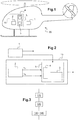
- a rotary wing aircraft 20 is shown.
- This aircraft 20 comprises an inertial unit 1 and a system 10 for analyzing and monitoring parasitic movements of the inertial unit 1 during an alignment phase of the inertial unit 1.
- This system 10 is shown in detail on the figure 2 and comprises a displacement sensor 2 of the aircraft 20 and an estimator 5 provided with a computer 3 and a memory 4.
- the displacement sensor 2 is a GNSS receiver and provides precise measurements of displacement relative to the ground of the aircraft 20, which can be measurements of speed or position, these measurements being based for example on the phase increments of the waves carrying signals transmitted by satellites of at least one GNSS system.
- the memory 4 stores calculation instructions and optionally validation thresholds for the alignment of the inertial unit 1.
- the computer 3 uses these calculation instructions, the displacement measurements and if necessary the validation thresholds for the alignment of the inertial unit 1 in order to implement an analysis and monitoring of parasitic movements of the inertial unit 1, a block diagram of which is shown on the figure 3 .
- the displacement sensor 2 is connected to the estimator 5 in order to provide it with the displacement measurements relative to the ground of the aircraft 20.
- the inertial unit 1 is connected to the system 10 in order to provide it with a start signal t 0 and an end signal t 1 of the alignment phase.
- This method of analyzing and monitoring parasitic movements of the inertial unit 1 during an alignment phase comprises two steps.
- An acquisition 110 of displacement measurements relative to the ground of the aircraft 20 is carried out, by means of the displacement sensor 2, during the alignment phase of the inertial unit 1.
- An estimate 120 of states of a mirror process is also carried out from the observations constituted by the displacement measurements.
- the model of the mirror process has a structure close to that of the model of the process of alignment of the inertial unit 1.
- the model of the mirror process can also be strictly identical to the model of the process of alignment of the inertial unit 1.
- a block diagram of an example of a model of the alignment process of the inertial unit 1 is represented on the figure 4 .
- ⁇ n is the orientation error around the North / South axis
- ⁇ e is the orientation error around the East / West axis
- ⁇ d is the error orientation around a vertical axis
- v n is the speed along the North / South axis
- v e is the speed along the East / West axis.
- This model of the alignment process takes into account the known latitude ⁇ of the aircraft 20 and uses the module of the acceleration of terrestrial gravity g on the one hand, and a vector representing the speed of rotation.
- the symbol ⁇ represents an adder and the symbol represents an integrator. Acceleration errors ⁇ n along the North / South axis and ⁇ e along the East / West axis are also indicated.
- An estimator of the states of the alignment process can then be a Kalman filter comprising these five states.
- one or more additional states may possibly be implemented.
- the latitude ⁇ of the aircraft 20, when it is unknown, can be an additional state of the alignment process and can then be determined by the estimator.
- the model of the mirror process used by the method according to the invention may include a model strictly identical to the model of the alignment process shown in the figure 4 .
- these two models have the same number of states and the same matrices defining the relationships between the states.
- the model of the mirror process can also be simplified or approximated compared to the model of the alignment process.
- the 24-hour mode linked to Earth's rotation has been neglected in particular to establish the mirror process represented in the form of a block diagram on the figure 5 .
- the method according to the invention makes it possible to identify the coefficients of these two polynomial functions.
- the figure 6 presents these measurements of the speed relative to the ground of the aircraft 20 along the North / South axis obtained during the alignment phase, namely between a start t 0 and an end t 1 of a phase of alignment, as well as a representation of the polynomial function corresponding to this speed along the North / South axis.
- the coefficients of these polynomial functions are directly linked to the states of the mirror process.
- the estimation 120 of states of the mirror process consists either in the estimation of these coefficients of each polynomial function, coefficients from which the states are deduced, or in the direct estimation of the states.
- This estimation 120 of the states of the mirror process can be carried out from the observations constituted by the displacement measurements by known mathematical methods such as the non-recursive least squares method or else the recursive least squares method or even by using a filter of Kalman.
- the method according to the invention can use in an additional step 130,140 these error estimates orientation and speeds of the inertial unit 1 due to parasitic movements during this alignment phase.
- this additional step of the method is a comparison 130 of the absolute value of at least one estimate of the orientation errors and of the speeds of the inertial unit 1 with at least one validation threshold and l 'activation of an "alignment not validated" signal if at least one of the thresholds is exceeded.
- this “alignment not validated” signal reveals that the accuracy of the data supplied by the inertial unit 1 is deemed to be insufficient, and that the alignment phase of the inertial unit 1 must for example be restarted, or that the aircraft must be operated in a mode which does not require inertial measurements.
- the additional step of the method consists of a correction 140 of the data supplied by the inertial unit 1.
- This correction 140 uses the estimates of the orientation errors and of the speeds of the inertial unit 1 resulting from parasitic movements during this alignment phase and previously calculated, in order to improve the data provided by the inertial unit 1 and to make them sufficiently precise to be usable.
- the displacement sensor can be arranged outside the system 10 and provide its displacement measurements to the system 10 so that it uses them.
Landscapes
- Engineering & Computer Science (AREA)
- Radar, Positioning & Navigation (AREA)
- Remote Sensing (AREA)
- Physics & Mathematics (AREA)
- General Physics & Mathematics (AREA)
- Manufacturing & Machinery (AREA)
- Automation & Control Theory (AREA)
- Navigation (AREA)
- Position Fixing By Use Of Radio Waves (AREA)
Claims (14)
- Verfahren zur Analyse und Überwachung von Störbewegungen einer inertialen Messeinheit (1) eines Luftfahrzeugs (20) während einer statischen Ausrichtungsphase der inertialen Messeinheit (1),
bei dem während der statischen Ausrichtungsphase der inertialen Messeinheit (1) das Verfahren die folgenden Schritte ausführt:- Erfassen (110) von Messungen der Bewegung des Luftfahrzeugs (20) in Bezug auf den Boden, die von einem Bewegungssensor des Luftfahrzeugs (20) bereitgestellt werden, und- Schätzen (120) der Zustände eines Spiegelprozesses, dessen Modell gegenüber dem Modell eines während der statischen Ausrichtungsphase verwendeten statischen Ausrichtungsprozesses der inertialen Messeinheit (1) vereinfacht und/oder angenähert ist,wobei die Schätzung der Zustände des Spiegelprozesses ausgehend von den durch die Bewegungsmessungen gebildeten Beobachtungen durchgeführt wird. - Verfahren nach Anspruch 1,
dadurch gekennzeichnet, dass Validierungsschwellenwerte der statischen Ausrichtung vor der statischen Ausrichtungsphase der inertialen Messeinheit (1) definiert wurden, und dass jeder Validierungsschwellenwert jeweils einem der geschätzten Zustände entspricht, wobei das Verfahren einen zusätzlichen Schritt des Vergleichens (130) des Absolutwerts von mindestens einer Schätzung eines der Zustände mit mindestens einem Validierungsschwellenwert umfasst. - Verfahren nach Anspruch 2,
dadurch gekennzeichnet, dass in dem zusätzlichen Vergleichsschritt (130) der Absolutwert mindestens einer Schätzung der Zustände mit dem entsprechenden Validierungsschwellenwert verglichen wird und ein "Ausrichtung nicht validiert"-Signal aktiviert wird, sobald der Absolutwert einer Schätzung eines Zustands über dem entsprechenden Validierungsschwellenwert liegt. - Verfahren nach Anspruch 2,
dadurch gekennzeichnet, dass in dem zusätzlichen Vergleichsschritt (130) mindestens zwei Schätzungen der Zustände kombiniert werden, um eine Kombination von geschätzten Zuständen zu bilden, und ein "Ausrichtung nicht validiert"-Signal aktiviert wird, wenn die Kombination von geschätzten Zuständen über einem Gesamtschwellenwert liegt. - Verfahren nach Anspruch 4,
dadurch gekennzeichnet, dass die Kombination von geschätzten Zuständen gleich einer gewichteten quadratischen Summe von mindestens zwei Schätzungen der Zustände ist. - Verfahren nach Anspruch 1,
dadurch gekennzeichnet, dass das Verfahren einen zusätzlichen Schritt des Korrigierens (140) der von der inertialen Messeinheit (1) gelieferten Daten umfasst, wobei der zusätzliche Schritt des Korrigierens (140) Schätzungen von Fehlern der Orientierung und von Geschwindigkeiten der inertialen Messeinheit (1) verwendet, die sich aus Störbewegungen während der Ausrichtungsphase ergeben, um die von der inertialen Messeinheit (1) bereitgestellten Daten nutzbar zu machen. - Verfahren nach Anspruch 6,
dadurch gekennzeichnet, dass in dem zusätzlichen Schritt des Korrigierens (140) die Korrektur anhand der geschätzten Zustände berechnet wird, wobei jeder geschätzte Zustand als Anfangswert eines Fehlerschätzprozesses der inertialen Messeinheit (1) verwendet wird, wobei der Fehlerschätzprozess über die gesamte Dauer einer auf die Ausrichtungsphase folgenden Navigationsphase der inertialen Messeinheit (1) aufrechterhalten wird und die aufrechterhaltenen Schätzungen der Fehler aus den von der inertialen Messeinheit (1) bereitgestellten Daten herausgerechnet werden. - Verfahren nach einem der Ansprüche 1 bis 7,
dadurch gekennzeichnet, dass während des Erfassens (110) die Messungen der Bewegung des Luftfahrzeugs (20) relativ zum Boden Messungen einer Geschwindigkeit relativ zum Boden (vg ) des Luftfahrzeugs (20) sind. - Verfahren nach einem der Ansprüche 1 bis 7,
dadurch gekennzeichnet, dass während der Erfassung (110) die Messungen der Bewegung des Luftfahrzeugs (20) relativ zum Boden Messungen einer Position relativ zum Boden (xg ) des Luftfahrzeugs (20) sind. - Verfahren nach einem der Ansprüche 1 bis 9,
dadurch gekennzeichnet, dass die Zustandsschätzung (120) des Spiegelprozesses darin besteht, die Koeffizienten mindestens einer den Bewegungsmessungen nahen Polynomfunktion der Zeit zu schätzen. - Verfahren nach Anspruch 10,
dadurch gekennzeichnet, dass, wenn die Bewegungsmessungen Messungen der Geschwindigkeit relativ zum Boden (vg ) sind, das Modell des Spiegelprozesses in der Lage ist, eine Polynomfunktion zweiten Grades in der Zeit für die Nord/Süd-Komponente der Geschwindigkeit relativ zum Boden und eine Polynomfunktion ersten Grades in der Zeit für die Ost/West Komponente der Geschwindigkeit zu erzeugen. - Verfahren nach einem der Ansprüche 10 bis 11,
dadurch gekennzeichnet, dass die Schätzung (120) von Zuständen des Spiegelprozesses nach dem Verfahren der kleinsten Quadrate durchgeführt wird, wobei die zu identifizierenden Koeffizienten diejenigen der mindestens einen Polynomfunktion der Zeit sind. - Verfahren nach einem der Ansprüche 1 bis 11,
dadurch gekennzeichnet, dass die Schätzung (120) der Zustände des Spiegelprozesses aus einer Kalman-Filterung besteht, deren Zustände diejenigen des Spiegelprozesses sind und deren Beobachtungen die Messungen der Bewegung relativ zum Boden sind. - System (10) zum Analysieren und Überwachen von Störbewegungen einer inertialen Messeinheit (1) während einer statischen Ausrichtungsphase, wobei das System (10) einen Sensor (2) für Bewegungen eines Luftfahrzeugs (20) umfasst, der Messungen der Bewegung relativ zum Boden des Luftfahrzeugs (20) liefert, so dass das System (10) einen Schätzer (5) eines gegenüber dem statischen Ausrichtungsprozess der inertialen Messeinheit (1) vereinfachten und/oder angenäherten Spiegelprozesses umfasst,
wobei der Schätzer (5) konfiguriert ist, um den Prozess nach den Ansprüchen 1 bis 13 durchzuführen, und mit mindestens einem Computer (3) und mindestens einem Speicher (4) versehen ist, der Validierungsschwellenwerte für die statische Ausrichtung der inertialen Messeinheit (1) und Rechenanweisungen speichert, wobei der Schätzer (5) es ermöglicht, Zustände des Spiegelprozesses zu schätzen, von dem ein Modell gegenüber dem Modell des statischen Ausrichtungsprozesses der inertialen Messeinheit (1) vereinfacht und/oder angenähert ist, wobei die Schätzung (120) der Zustände des Spiegelprozesses auf der Grundlage von Beobachtungen durchgeführt wird, die durch vom dem Bewegungssensor (2) gelieferte Bewegungsmessungen gebildet werden.
Applications Claiming Priority (1)
| Application Number | Priority Date | Filing Date | Title |
|---|---|---|---|
| FR1770355A FR3065067B1 (fr) | 2017-04-07 | 2017-04-07 | Systeme et procede d'analyse et de surveillance des mouvements parasites d'une centrale inertielle pendant une phase d'alignement statique. |
Publications (2)
| Publication Number | Publication Date |
|---|---|
| EP3385677A1 EP3385677A1 (de) | 2018-10-10 |
| EP3385677B1 true EP3385677B1 (de) | 2020-01-22 |
Family
ID=59521143
Family Applications (1)
| Application Number | Title | Priority Date | Filing Date |
|---|---|---|---|
| EP18164005.3A Active EP3385677B1 (de) | 2017-04-07 | 2018-03-26 | System und verfahren zur analyse und überwachung der störenden bewegungen eines trägheitsnavigationssystems während einer statischen ausrichtungsphase |
Country Status (3)
| Country | Link |
|---|---|
| US (2) | US11022462B2 (de) |
| EP (1) | EP3385677B1 (de) |
| FR (1) | FR3065067B1 (de) |
Families Citing this family (3)
| Publication number | Priority date | Publication date | Assignee | Title |
|---|---|---|---|---|
| FR3065067B1 (fr) * | 2017-04-07 | 2020-02-28 | Airbus Helicopters | Systeme et procede d'analyse et de surveillance des mouvements parasites d'une centrale inertielle pendant une phase d'alignement statique. |
| US11193772B1 (en) * | 2018-03-09 | 2021-12-07 | Greensea Systems, Inc. | Autonomous merit-based heading alignment and initialization methods for inertial navigation systems, and apparatuses and software incorporating same |
| CN111308457B (zh) * | 2019-12-11 | 2021-11-16 | 成都汇蓉国科微系统技术有限公司 | 脉冲多普勒雷达寻北的方法、系统及存储介质 |
Citations (3)
| Publication number | Priority date | Publication date | Assignee | Title |
|---|---|---|---|---|
| US20100161223A1 (en) * | 2008-12-22 | 2010-06-24 | Sagem Defense Securite | Method of determining a heading in the geographical north direction by means of an inertial unit |
| WO2011045032A1 (en) * | 2009-10-15 | 2011-04-21 | Sagem Defense Securite | A method of detecting parasitic movements while aligning an inertial unit |
| EP2330382A2 (de) * | 2009-12-03 | 2011-06-08 | Honeywell International Inc. | Verfahren und System zur Schätzung der Navigationsqualität in anpassung an den Breitengrad |
Family Cites Families (8)
| Publication number | Priority date | Publication date | Assignee | Title |
|---|---|---|---|---|
| US4032759A (en) * | 1975-10-24 | 1977-06-28 | The Singer Company | Shipboard reference for an aircraft navigation system |
| US4254465A (en) * | 1978-08-03 | 1981-03-03 | Dynamic Sciences International, Inc. | Strap-down attitude and heading reference system |
| FR2668447B1 (fr) * | 1990-10-29 | 1993-01-22 | Aerospatiale | Systeme pour l'alignement de la centrale inertielle d'un vehicule porte sur celle d'un vehicule porteur. |
| US7606665B2 (en) * | 2003-08-29 | 2009-10-20 | Honeywell International Inc. | System and method for employing an aided-alignment mode to align an inertial reference system |
| US7512493B2 (en) * | 2006-05-31 | 2009-03-31 | Honeywell International Inc. | High speed gyrocompass alignment via multiple Kalman filter based hypothesis testing |
| FR2951935B1 (fr) | 2009-11-03 | 2012-02-17 | Sedatelec | Dispositif de traitement par moxibustion |
| US20110313614A1 (en) * | 2010-06-21 | 2011-12-22 | Hinnant Jr Harris O | Integrated aeroelasticity measurement for vehicle health management |
| FR3065067B1 (fr) * | 2017-04-07 | 2020-02-28 | Airbus Helicopters | Systeme et procede d'analyse et de surveillance des mouvements parasites d'une centrale inertielle pendant une phase d'alignement statique. |
-
2017
- 2017-04-07 FR FR1770355A patent/FR3065067B1/fr not_active Expired - Fee Related
-
2018
- 2018-03-26 EP EP18164005.3A patent/EP3385677B1/de active Active
- 2018-04-04 US US15/945,525 patent/US11022462B2/en active Active
-
2021
- 2021-04-12 US US17/228,080 patent/US11454517B2/en active Active
Patent Citations (3)
| Publication number | Priority date | Publication date | Assignee | Title |
|---|---|---|---|---|
| US20100161223A1 (en) * | 2008-12-22 | 2010-06-24 | Sagem Defense Securite | Method of determining a heading in the geographical north direction by means of an inertial unit |
| WO2011045032A1 (en) * | 2009-10-15 | 2011-04-21 | Sagem Defense Securite | A method of detecting parasitic movements while aligning an inertial unit |
| EP2330382A2 (de) * | 2009-12-03 | 2011-06-08 | Honeywell International Inc. | Verfahren und System zur Schätzung der Navigationsqualität in anpassung an den Breitengrad |
Also Published As
| Publication number | Publication date |
|---|---|
| EP3385677A1 (de) | 2018-10-10 |
| US20210302196A1 (en) | 2021-09-30 |
| US20180292232A1 (en) | 2018-10-11 |
| FR3065067B1 (fr) | 2020-02-28 |
| US11454517B2 (en) | 2022-09-27 |
| US11022462B2 (en) | 2021-06-01 |
| FR3065067A1 (fr) | 2018-10-12 |
Similar Documents
| Publication | Publication Date | Title |
|---|---|---|
| EP3623758B1 (de) | Standortbestimmungssystem und entsprechendes standortbestimmungsverfahren | |
| EP2299287B1 (de) | Hybrides System und Vorrichtung zur Berechnung der Position und zur Überwachung der Integrität | |
| EP2495530B1 (de) | Verfahren und System zur Bestimmung der Fluglage eines Luftfahrzeugs mit Hilfe von mehrachsigen Beschleunigungsmessungen | |
| EP2541200B1 (de) | Navigationsvorrichtung und -verfahren, das aus mehreren fahrzeugfest montierten Hybridnavigationssystemen besteht | |
| EP2374022B1 (de) | Durch konstruktion eingebaute integrierte hybridisierungseinrichtung mit geschlossener schleife | |
| EP2449409B1 (de) | Verfahren zur bestimmung der position eines mobilen körpers in einem bestimmten moment und zur überwachung der integrität der position des mobilen körpers | |
| FR2943869A1 (fr) | Procede et dispositif de detection et d'exclusion de pannes satellite dans un systeme hybride ins/gnss | |
| EP1801539B1 (de) | Hybridisierungsvorrichtung mit geschlossenem Regelkreis und Überwachung der Integrität der Maßnahmen | |
| WO2012013525A1 (fr) | Procede de determination d'un volume de protection dans le cas de deux pannes satellitaires simultanees | |
| EP3385677B1 (de) | System und verfahren zur analyse und überwachung der störenden bewegungen eines trägheitsnavigationssystems während einer statischen ausrichtungsphase | |
| FR3023918A1 (fr) | Procede d'estimation de la vitesses d'un aeronef par rapport a l'air environnant, et systeme associe | |
| EP3869155A1 (de) | Verfahren zur positionsbestimmung und orientierung eines fahrzeugs | |
| EP3896398B1 (de) | Verfahren zur identifizierung einer statischen phase eines fahrzeugs | |
| EP2366116A1 (de) | Hybridisierungseinrichtung mit getrennten kalmanfiltern | |
| EP3006897B1 (de) | Navigationsverfahren eines fahrzeugs, navigationsvorrichtung und fahrzeug für die umsetzung dieses verfahrens | |
| WO2021156569A1 (fr) | Procede d'aide à la navigation d'un porteur mobile | |
| EP1956386A1 (de) | Verfahren zur Positionsbestimmung eines mobilen Körpers und einer Schutzgrenze um diese Position | |
| EP4551973A1 (de) | Navigations- und positionierungsvorrichtung und -verfahren | |
| FR3023919A1 (fr) | Procede d'estimation de la vitesse d'un aeronef par rapport a l'air environnant, et systeme associe | |
| WO2024132656A1 (fr) | Dispositif et procede de navigation utilisant des donnees pre-integrees de façon asynchrone dans une umi distante | |
| EP4545909A1 (de) | Verfahren zur ausrichtung eines trägheitsnavigationssystems | |
| WO2024008942A1 (fr) | Dispositif de navigation et de positionnement | |
| WO2024008635A1 (fr) | Dispositif et procede de maintien de l'integrite du positionnement d'un vehicule independamment de la vulnerabilite de donnees satellitaires | |
| WO2024132657A1 (fr) | Dispositif et procede de navigation utilisant des donnees de correction dans une umi distante | |
| FR3157554A1 (fr) | Procédé d'estimation de la distance à un objet, calculateur, système et porteur associés |
Legal Events
| Date | Code | Title | Description |
|---|---|---|---|
| PUAI | Public reference made under article 153(3) epc to a published international application that has entered the european phase |
Free format text: ORIGINAL CODE: 0009012 |
|
| STAA | Information on the status of an ep patent application or granted ep patent |
Free format text: STATUS: THE APPLICATION HAS BEEN PUBLISHED |
|
| AK | Designated contracting states |
Kind code of ref document: A1 Designated state(s): AL AT BE BG CH CY CZ DE DK EE ES FI FR GB GR HR HU IE IS IT LI LT LU LV MC MK MT NL NO PL PT RO RS SE SI SK SM TR |
|
| AX | Request for extension of the european patent |
Extension state: BA ME |
|
| STAA | Information on the status of an ep patent application or granted ep patent |
Free format text: STATUS: REQUEST FOR EXAMINATION WAS MADE |
|
| 17P | Request for examination filed |
Effective date: 20181025 |
|
| RBV | Designated contracting states (corrected) |
Designated state(s): AL AT BE BG CH CY CZ DE DK EE ES FI FR GB GR HR HU IE IS IT LI LT LU LV MC MK MT NL NO PL PT RO RS SE SI SK SM TR |
|
| GRAP | Despatch of communication of intention to grant a patent |
Free format text: ORIGINAL CODE: EPIDOSNIGR1 |
|
| STAA | Information on the status of an ep patent application or granted ep patent |
Free format text: STATUS: GRANT OF PATENT IS INTENDED |
|
| INTG | Intention to grant announced |
Effective date: 20191022 |
|
| GRAS | Grant fee paid |
Free format text: ORIGINAL CODE: EPIDOSNIGR3 |
|
| GRAA | (expected) grant |
Free format text: ORIGINAL CODE: 0009210 |
|
| STAA | Information on the status of an ep patent application or granted ep patent |
Free format text: STATUS: THE PATENT HAS BEEN GRANTED |
|
| AK | Designated contracting states |
Kind code of ref document: B1 Designated state(s): AL AT BE BG CH CY CZ DE DK EE ES FI FR GB GR HR HU IE IS IT LI LT LU LV MC MK MT NL NO PL PT RO RS SE SI SK SM TR |
|
| REG | Reference to a national code |
Ref country code: GB Ref legal event code: FG4D Free format text: NOT ENGLISH |
|
| REG | Reference to a national code |
Ref country code: CH Ref legal event code: EP |
|
| REG | Reference to a national code |
Ref country code: AT Ref legal event code: REF Ref document number: 1227193 Country of ref document: AT Kind code of ref document: T Effective date: 20200215 |
|
| REG | Reference to a national code |
Ref country code: IE Ref legal event code: FG4D Free format text: LANGUAGE OF EP DOCUMENT: FRENCH |
|
| REG | Reference to a national code |
Ref country code: DE Ref legal event code: R096 Ref document number: 602018002064 Country of ref document: DE |
|
| REG | Reference to a national code |
Ref country code: NL Ref legal event code: MP Effective date: 20200122 |
|
| REG | Reference to a national code |
Ref country code: LT Ref legal event code: MG4D |
|
| PG25 | Lapsed in a contracting state [announced via postgrant information from national office to epo] |
Ref country code: FI Free format text: LAPSE BECAUSE OF FAILURE TO SUBMIT A TRANSLATION OF THE DESCRIPTION OR TO PAY THE FEE WITHIN THE PRESCRIBED TIME-LIMIT Effective date: 20200122 Ref country code: NO Free format text: LAPSE BECAUSE OF FAILURE TO SUBMIT A TRANSLATION OF THE DESCRIPTION OR TO PAY THE FEE WITHIN THE PRESCRIBED TIME-LIMIT Effective date: 20200422 Ref country code: PT Free format text: LAPSE BECAUSE OF FAILURE TO SUBMIT A TRANSLATION OF THE DESCRIPTION OR TO PAY THE FEE WITHIN THE PRESCRIBED TIME-LIMIT Effective date: 20200614 Ref country code: NL Free format text: LAPSE BECAUSE OF FAILURE TO SUBMIT A TRANSLATION OF THE DESCRIPTION OR TO PAY THE FEE WITHIN THE PRESCRIBED TIME-LIMIT Effective date: 20200122 Ref country code: RS Free format text: LAPSE BECAUSE OF FAILURE TO SUBMIT A TRANSLATION OF THE DESCRIPTION OR TO PAY THE FEE WITHIN THE PRESCRIBED TIME-LIMIT Effective date: 20200122 |
|
| PG25 | Lapsed in a contracting state [announced via postgrant information from national office to epo] |
Ref country code: GR Free format text: LAPSE BECAUSE OF FAILURE TO SUBMIT A TRANSLATION OF THE DESCRIPTION OR TO PAY THE FEE WITHIN THE PRESCRIBED TIME-LIMIT Effective date: 20200423 Ref country code: IS Free format text: LAPSE BECAUSE OF FAILURE TO SUBMIT A TRANSLATION OF THE DESCRIPTION OR TO PAY THE FEE WITHIN THE PRESCRIBED TIME-LIMIT Effective date: 20200522 Ref country code: HR Free format text: LAPSE BECAUSE OF FAILURE TO SUBMIT A TRANSLATION OF THE DESCRIPTION OR TO PAY THE FEE WITHIN THE PRESCRIBED TIME-LIMIT Effective date: 20200122 Ref country code: LV Free format text: LAPSE BECAUSE OF FAILURE TO SUBMIT A TRANSLATION OF THE DESCRIPTION OR TO PAY THE FEE WITHIN THE PRESCRIBED TIME-LIMIT Effective date: 20200122 Ref country code: SE Free format text: LAPSE BECAUSE OF FAILURE TO SUBMIT A TRANSLATION OF THE DESCRIPTION OR TO PAY THE FEE WITHIN THE PRESCRIBED TIME-LIMIT Effective date: 20200122 Ref country code: BG Free format text: LAPSE BECAUSE OF FAILURE TO SUBMIT A TRANSLATION OF THE DESCRIPTION OR TO PAY THE FEE WITHIN THE PRESCRIBED TIME-LIMIT Effective date: 20200422 |
|
| REG | Reference to a national code |
Ref country code: DE Ref legal event code: R119 Ref document number: 602018002064 Country of ref document: DE |
|
| PG25 | Lapsed in a contracting state [announced via postgrant information from national office to epo] |
Ref country code: MC Free format text: LAPSE BECAUSE OF FAILURE TO SUBMIT A TRANSLATION OF THE DESCRIPTION OR TO PAY THE FEE WITHIN THE PRESCRIBED TIME-LIMIT Effective date: 20200122 Ref country code: RO Free format text: LAPSE BECAUSE OF FAILURE TO SUBMIT A TRANSLATION OF THE DESCRIPTION OR TO PAY THE FEE WITHIN THE PRESCRIBED TIME-LIMIT Effective date: 20200122 Ref country code: ES Free format text: LAPSE BECAUSE OF FAILURE TO SUBMIT A TRANSLATION OF THE DESCRIPTION OR TO PAY THE FEE WITHIN THE PRESCRIBED TIME-LIMIT Effective date: 20200122 Ref country code: CZ Free format text: LAPSE BECAUSE OF FAILURE TO SUBMIT A TRANSLATION OF THE DESCRIPTION OR TO PAY THE FEE WITHIN THE PRESCRIBED TIME-LIMIT Effective date: 20200122 Ref country code: LT Free format text: LAPSE BECAUSE OF FAILURE TO SUBMIT A TRANSLATION OF THE DESCRIPTION OR TO PAY THE FEE WITHIN THE PRESCRIBED TIME-LIMIT Effective date: 20200122 Ref country code: EE Free format text: LAPSE BECAUSE OF FAILURE TO SUBMIT A TRANSLATION OF THE DESCRIPTION OR TO PAY THE FEE WITHIN THE PRESCRIBED TIME-LIMIT Effective date: 20200122 Ref country code: SM Free format text: LAPSE BECAUSE OF FAILURE TO SUBMIT A TRANSLATION OF THE DESCRIPTION OR TO PAY THE FEE WITHIN THE PRESCRIBED TIME-LIMIT Effective date: 20200122 Ref country code: DK Free format text: LAPSE BECAUSE OF FAILURE TO SUBMIT A TRANSLATION OF THE DESCRIPTION OR TO PAY THE FEE WITHIN THE PRESCRIBED TIME-LIMIT Effective date: 20200122 Ref country code: SK Free format text: LAPSE BECAUSE OF FAILURE TO SUBMIT A TRANSLATION OF THE DESCRIPTION OR TO PAY THE FEE WITHIN THE PRESCRIBED TIME-LIMIT Effective date: 20200122 |
|
| REG | Reference to a national code |
Ref country code: AT Ref legal event code: MK05 Ref document number: 1227193 Country of ref document: AT Kind code of ref document: T Effective date: 20200122 |
|
| PLBE | No opposition filed within time limit |
Free format text: ORIGINAL CODE: 0009261 |
|
| STAA | Information on the status of an ep patent application or granted ep patent |
Free format text: STATUS: NO OPPOSITION FILED WITHIN TIME LIMIT |
|
| REG | Reference to a national code |
Ref country code: BE Ref legal event code: MM Effective date: 20200331 |
|
| 26N | No opposition filed |
Effective date: 20201023 |
|
| PG25 | Lapsed in a contracting state [announced via postgrant information from national office to epo] |
Ref country code: LU Free format text: LAPSE BECAUSE OF NON-PAYMENT OF DUE FEES Effective date: 20200326 |
|
| PG25 | Lapsed in a contracting state [announced via postgrant information from national office to epo] |
Ref country code: AT Free format text: LAPSE BECAUSE OF FAILURE TO SUBMIT A TRANSLATION OF THE DESCRIPTION OR TO PAY THE FEE WITHIN THE PRESCRIBED TIME-LIMIT Effective date: 20200122 Ref country code: DE Free format text: LAPSE BECAUSE OF NON-PAYMENT OF DUE FEES Effective date: 20201001 Ref country code: IE Free format text: LAPSE BECAUSE OF NON-PAYMENT OF DUE FEES Effective date: 20200326 |
|
| PG25 | Lapsed in a contracting state [announced via postgrant information from national office to epo] |
Ref country code: PL Free format text: LAPSE BECAUSE OF FAILURE TO SUBMIT A TRANSLATION OF THE DESCRIPTION OR TO PAY THE FEE WITHIN THE PRESCRIBED TIME-LIMIT Effective date: 20200122 Ref country code: SI Free format text: LAPSE BECAUSE OF FAILURE TO SUBMIT A TRANSLATION OF THE DESCRIPTION OR TO PAY THE FEE WITHIN THE PRESCRIBED TIME-LIMIT Effective date: 20200122 Ref country code: BE Free format text: LAPSE BECAUSE OF NON-PAYMENT OF DUE FEES Effective date: 20200331 |
|
| REG | Reference to a national code |
Ref country code: CH Ref legal event code: PL |
|
| PG25 | Lapsed in a contracting state [announced via postgrant information from national office to epo] |
Ref country code: LI Free format text: LAPSE BECAUSE OF NON-PAYMENT OF DUE FEES Effective date: 20210331 Ref country code: CH Free format text: LAPSE BECAUSE OF NON-PAYMENT OF DUE FEES Effective date: 20210331 |
|
| PG25 | Lapsed in a contracting state [announced via postgrant information from national office to epo] |
Ref country code: TR Free format text: LAPSE BECAUSE OF FAILURE TO SUBMIT A TRANSLATION OF THE DESCRIPTION OR TO PAY THE FEE WITHIN THE PRESCRIBED TIME-LIMIT Effective date: 20200122 Ref country code: MT Free format text: LAPSE BECAUSE OF FAILURE TO SUBMIT A TRANSLATION OF THE DESCRIPTION OR TO PAY THE FEE WITHIN THE PRESCRIBED TIME-LIMIT Effective date: 20200122 Ref country code: CY Free format text: LAPSE BECAUSE OF FAILURE TO SUBMIT A TRANSLATION OF THE DESCRIPTION OR TO PAY THE FEE WITHIN THE PRESCRIBED TIME-LIMIT Effective date: 20200122 |
|
| PG25 | Lapsed in a contracting state [announced via postgrant information from national office to epo] |
Ref country code: MK Free format text: LAPSE BECAUSE OF FAILURE TO SUBMIT A TRANSLATION OF THE DESCRIPTION OR TO PAY THE FEE WITHIN THE PRESCRIBED TIME-LIMIT Effective date: 20200122 Ref country code: AL Free format text: LAPSE BECAUSE OF FAILURE TO SUBMIT A TRANSLATION OF THE DESCRIPTION OR TO PAY THE FEE WITHIN THE PRESCRIBED TIME-LIMIT Effective date: 20200122 |
|
| P01 | Opt-out of the competence of the unified patent court (upc) registered |
Effective date: 20230530 |
|
| PGFP | Annual fee paid to national office [announced via postgrant information from national office to epo] |
Ref country code: GB Payment date: 20260324 Year of fee payment: 9 |
|
| PGFP | Annual fee paid to national office [announced via postgrant information from national office to epo] |
Ref country code: IT Payment date: 20260324 Year of fee payment: 9 |
|
| PGFP | Annual fee paid to national office [announced via postgrant information from national office to epo] |
Ref country code: FR Payment date: 20260320 Year of fee payment: 9 |