EP3385682A1 - Nichtinvasives radarfüllstandmessgerät - Google Patents
Nichtinvasives radarfüllstandmessgerät Download PDFInfo
- Publication number
- EP3385682A1 EP3385682A1 EP18164946.8A EP18164946A EP3385682A1 EP 3385682 A1 EP3385682 A1 EP 3385682A1 EP 18164946 A EP18164946 A EP 18164946A EP 3385682 A1 EP3385682 A1 EP 3385682A1
- Authority
- EP
- European Patent Office
- Prior art keywords
- tank wall
- bellows
- tank
- suction cup
- radar level
- Prior art date
- Legal status (The legal status is an assumption and is not a legal conclusion. Google has not performed a legal analysis and makes no representation as to the accuracy of the status listed.)
- Granted
Links
Images



Classifications
-
- G—PHYSICS
- G01—MEASURING; TESTING
- G01S—RADIO DIRECTION-FINDING; RADIO NAVIGATION; DETERMINING DISTANCE OR VELOCITY BY USE OF RADIO WAVES; LOCATING OR PRESENCE-DETECTING BY USE OF THE REFLECTION OR RERADIATION OF RADIO WAVES; ANALOGOUS ARRANGEMENTS USING OTHER WAVES
- G01S13/00—Systems using the reflection or reradiation of radio waves, e.g. radar systems; Analogous systems using reflection or reradiation of waves whose nature or wavelength is irrelevant or unspecified
- G01S13/02—Systems using reflection of radio waves, e.g. primary radar systems; Analogous systems
-
- B—PERFORMING OPERATIONS; TRANSPORTING
- B65—CONVEYING; PACKING; STORING; HANDLING THIN OR FILAMENTARY MATERIAL
- B65D—CONTAINERS FOR STORAGE OR TRANSPORT OF ARTICLES OR MATERIALS, e.g. BAGS, BARRELS, BOTTLES, BOXES, CANS, CARTONS, CRATES, DRUMS, JARS, TANKS, HOPPERS, FORWARDING CONTAINERS; ACCESSORIES, CLOSURES, OR FITTINGS THEREFOR; PACKAGING ELEMENTS; PACKAGES
- B65D90/00—Component parts, details or accessories for large containers
- B65D90/48—Arrangements of indicating or measuring devices
-
- G—PHYSICS
- G01—MEASURING; TESTING
- G01F—MEASURING VOLUME, VOLUME FLOW, MASS FLOW OR LIQUID LEVEL; METERING BY VOLUME
- G01F23/00—Indicating or measuring liquid level or level of fluent solid material, e.g. indicating in terms of volume or indicating by means of an alarm
- G01F23/22—Indicating or measuring liquid level or level of fluent solid material, e.g. indicating in terms of volume or indicating by means of an alarm by measuring physical variables, other than linear dimensions, pressure or weight, dependent on the level to be measured, e.g. by difference of heat transfer of steam or water
- G01F23/28—Indicating or measuring liquid level or level of fluent solid material, e.g. indicating in terms of volume or indicating by means of an alarm by measuring physical variables, other than linear dimensions, pressure or weight, dependent on the level to be measured, e.g. by difference of heat transfer of steam or water by measuring the variations of parameters of electromagnetic or acoustic waves applied directly to the liquid or fluent solid material
- G01F23/284—Electromagnetic waves
-
- F—MECHANICAL ENGINEERING; LIGHTING; HEATING; WEAPONS; BLASTING
- F16—ENGINEERING ELEMENTS AND UNITS; GENERAL MEASURES FOR PRODUCING AND MAINTAINING EFFECTIVE FUNCTIONING OF MACHINES OR INSTALLATIONS; THERMAL INSULATION IN GENERAL
- F16B—DEVICES FOR FASTENING OR SECURING CONSTRUCTIONAL ELEMENTS OR MACHINE PARTS TOGETHER, e.g. NAILS, BOLTS, CIRCLIPS, CLAMPS, CLIPS OR WEDGES; JOINTS OR JOINTING
- F16B47/00—Suction cups for attaching purposes; Equivalent means using adhesives
- F16B47/006—Suction cups for attaching purposes; Equivalent means using adhesives the suction cups being activated by the rotation of a cranked lever arm
-
- G—PHYSICS
- G01—MEASURING; TESTING
- G01F—MEASURING VOLUME, VOLUME FLOW, MASS FLOW OR LIQUID LEVEL; METERING BY VOLUME
- G01F25/00—Testing or calibration of apparatus for measuring volume, volume flow or liquid level or for metering by volume
- G01F25/20—Testing or calibration of apparatus for measuring volume, volume flow or liquid level or for metering by volume of apparatus for measuring liquid level
-
- G—PHYSICS
- G01—MEASURING; TESTING
- G01S—RADIO DIRECTION-FINDING; RADIO NAVIGATION; DETERMINING DISTANCE OR VELOCITY BY USE OF RADIO WAVES; LOCATING OR PRESENCE-DETECTING BY USE OF THE REFLECTION OR RERADIATION OF RADIO WAVES; ANALOGOUS ARRANGEMENTS USING OTHER WAVES
- G01S13/00—Systems using the reflection or reradiation of radio waves, e.g. radar systems; Analogous systems using reflection or reradiation of waves whose nature or wavelength is irrelevant or unspecified
- G01S13/02—Systems using reflection of radio waves, e.g. primary radar systems; Analogous systems
- G01S13/06—Systems determining position data of a target
- G01S13/08—Systems for measuring distance only
-
- G—PHYSICS
- G01—MEASURING; TESTING
- G01S—RADIO DIRECTION-FINDING; RADIO NAVIGATION; DETERMINING DISTANCE OR VELOCITY BY USE OF RADIO WAVES; LOCATING OR PRESENCE-DETECTING BY USE OF THE REFLECTION OR RERADIATION OF RADIO WAVES; ANALOGOUS ARRANGEMENTS USING OTHER WAVES
- G01S13/00—Systems using the reflection or reradiation of radio waves, e.g. radar systems; Analogous systems using reflection or reradiation of waves whose nature or wavelength is irrelevant or unspecified
- G01S13/88—Radar or analogous systems specially adapted for specific applications
-
- H—ELECTRICITY
- H01—ELECTRIC ELEMENTS
- H01Q—ANTENNAS, i.e. RADIO AERIALS
- H01Q1/00—Details of, or arrangements associated with, antennas
- H01Q1/12—Supports; Mounting means
- H01Q1/22—Supports; Mounting means by structural association with other equipment or articles
- H01Q1/225—Supports; Mounting means by structural association with other equipment or articles used in level-measurement devices, e.g. for level gauge measurement
-
- H—ELECTRICITY
- H01—ELECTRIC ELEMENTS
- H01Q—ANTENNAS, i.e. RADIO AERIALS
- H01Q13/00—Waveguide horns or mouths; Slot antennas; Leaky-waveguide antennas; Equivalent structures causing radiation along the transmission path of a guided wave
- H01Q13/02—Waveguide horns
-
- H—ELECTRICITY
- H01—ELECTRIC ELEMENTS
- H01Q—ANTENNAS, i.e. RADIO AERIALS
- H01Q13/00—Waveguide horns or mouths; Slot antennas; Leaky-waveguide antennas; Equivalent structures causing radiation along the transmission path of a guided wave
- H01Q13/20—Non-resonant leaky-waveguide or transmission-line antennas; Equivalent structures causing radiation along the transmission path of a guided wave
Definitions
- the present invention relates to a radar level gauging arrangement for performing radar level gauging through a radar transmissive tank wall.
- radar level gauging is widely used for level gauging in tanks.
- radar level gauging has been used in relatively large tank installations, such as refinery tanks and tanks on cargo ships.
- applications also include smaller tanks, e.g. in process industry.
- the radar level gauge must be mounted in an opening in the tank wall, in order for the radar signals to enter the tank.
- tank walls are flexible, and a hole in the tank wall may not provide sufficient structural strength.
- a radar level gauging arrangement for performing radar level gauging in a tank having a tank wall which are impermeable to a product held in the tank and transmissive or transparent to radar signals, comprising an attachment device configured to be secured to a substantially flat portion of the tank wall, without penetration of the tank wall, and a radar level gauge including a directional antenna, the radar level gauge being mounted to the attachment device, such that, when the attachment device is secured against the tank wall, the directional antenna is positioned so as to enable transmission of radar signals through the tank wall, thereby enabling determination of a filling level in the tank.
- a radar level gauging arrangement for performing radar level gauging through a tank wall which is impermeable to a product held in the tank and transmissive to radar signals, comprising:
- the invention is based on the realization that radar level gauging in many situations may be performed through the walls of the tank containing the product to be gauged.
- radar level gauging By mounting a radar level gauge to an attachment device which can be secured to the tank wall without penetrating the tank wall, radar level gauging can thus be provided without damaging or interfering with the tank.
- Such radar level gauging can be referred to as "non-invasive" radar level gauging.
- the attachment device is a suction cup configured to be secured to the tank wall by means of partial vacuum created between the device and the tank wall. Attachment by suction is well known per se, and may be a simple, yet effective way of attaching the radar level gauge to many types of tank walls. Many types of suction cups for various applications are known in the art, and by mounting a radar level gauge to an appropriate suction cup a rudimentary radar level arrangement may be provided.
- a suction cup enables simple and reliable fastening on virtually any sufficiently smooth tank wall. For example, the surface of a plastic storage tank will typically be sufficiently smooth.
- the arrangement includes two or more suction cups, joined by a structure extending between the suction cups.
- the radar level gauge may then be mounted to the structure, preferably in between the suction cups.
- the at least one suction cup may include a connection terminal configured to be connected to an active source of sub-atmospheric pressure.
- the partial vacuum is created by the active source, e.g. a vacuum pump.
- active suction may provide a stronger suction attachment, especially as long as the active source is connected.
- the terminal may be provided with a sealing valve, to allow disconnection of the active source without removing the partial vacuum.
- the suction cup is configured to allow a user to create the partial vacuum by mechanical operation of the suction cup.
- a simple example of a mechanically operated suction cup includes a body with a ring-shaped surface, a bellows resting against the ring-shaped surface, the bellows configured to be placed between the body and the tank wall, and a bellows operating member attached to a portion of the bellows located within the ring-shaped surface, the bellows operating member being movably arranged with respect to the body between a first state, wherein the bellows is essentially coplanar with a plane of the ring-shaped surface, and a second state, in which the portion is brought out of the plane.
- suction cup is widely used e.g. as glass handles, sometimes with several suction cups combined in one handle.
- the radar level gauging arrangement comprises a suction cup including a main body having an inner ring-shaped surface and an outer ring-shaped surface, the inner and outer ring-shaped surfaces substantially extending in one single attachment plane, an annular bellows having an inner perimeter surrounding a central opening and an outer perimeter, a first side of the annular bellows configured to be placed against the tank wall, and a second side, opposite to the first side, facing the body with the inner perimeter aligned with the inner ring-shaped surface and the outer perimeter aligned with the outer ring-shaped surface, and a bellows operating member attached to a portion of the bellows extending between the inner and outer perimeter, the bellows operating member being movably arranged in relation to the main body to pull the portion into the main body away from the attachment plane.
- a radar level gauge including a directional antenna may then be mounted to the body such that the directional antenna is directed towards the central opening.
- the suction cup When the suction cup is placed against the tank wall and the bellows is pulled away from the attachment plane, a partial vacuum is created between the annular bellows and the tank wall thereby securing the vacuum device and the radar level gauge with respect to the tank wall, whereby the directional antenna is positioned to emit radar signals through the tank wall in the central opening.
- the baffle is here sandwiched between the tank wall and the two ring-shaped surfaces.
- the suction cup according to this embodiment can thus create a vacuum between the tank wall and the baffle in an annular compartment between the inner and outer ring-shaped surfaces.
- the central opening of the bellows provides direct access to the tank wall.
- the radar level gauge is mounted with its antenna directed towards this opening, the RLG will be able to emit transmit signals which propagate through the tank wall and into the tank, and also be able to receive a reflected return signal through the tank wall.
- the radar level gauge may be pivotably mounted to the attachment device, so that, when the attachment device is secured to the tank wall, the orientation of the directional antenna is adjustable with respect to a surface of the product in the tank. Such adjustable mounting may be advantageous if the tank wall is not perfectly horizontal.
- the directional antenna may then be slightly adjusted so that radar signals emitted from the antenna are directed substantially normal to the product surface, and reflected signals are directed substantially towards the antenna.
- an adhesive may be applied at least to an outer perimeter of the bellows, such that, when the suction cup is secured to the tank wall, the adhesive is pressed against the tank wall so as to create an adhesive bond.
- the suction applied by the suction cup can be seen primarily as an effective way to ensure a satisfactory adhesive bond.
- the ring-shaped surface(s) preferably has/have a width d of at least three millimeters, and preferable at least five millimeters, in order to compensate for small unevenness of the wall surface.
- this object is achieved by a method for performing radar level gauging in a tank having a radar transmissive tank wall, providing a radar level gauge mounted to a suction cup, placing a bellows of the suction cup against a substantially flat portion of the tank wall, creating a partial vacuum between the bellows and the tank wall to secure the suction cup to the tank wall, thereby fixating the radar level gauge with respect to the tank wall, emitting radar transmit signals through the tank wall, receiving radar echo signals through the tank wall, the echo signals formed by reflection of the transmit signals in a product surface inside the tank, and determining a filling level of the tank based on a relationship between the transmit signals and the echo signals.
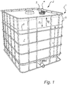
- FIG. 1 shows a plastic storage tank 1 provide with a level gauging arrangement 2 according to an embodiment of the present invention.
- the illustrated tank is a so called intermediate bulk container (IBC), or pallet tank, which is a reusable industrial container designed for the transport and storage of bulk liquid and granulated substances, such as chemicals, food ingredients, solvents, pharmaceuticals, etc (for reference, see e.g. https://en.wikipedia.org/wiki/Intermediate bulk container ).
- IBC intermediate bulk container
- pallet tank which is a reusable industrial container designed for the transport and storage of bulk liquid and granulated substances, such as chemicals, food ingredients, solvents, pharmaceuticals, etc (for reference, see e.g. https://en.wikipedia.org/wiki/Intermediate bulk container ).
- the walls 5 of the container are impermeable to the product stored in the tank.
- the tank wall 5 are typically transmissive (or transparent) to radar signals, at least to such an extent that radar level gauging can be performed through the tank wall 5.
- the radar level gauging arrangement 2 includes an attachment device, here a suction cup 3 firmly attached to the upper side of the tank, and a radar level gauge (RLG) 4 mounted to the suction device 3.
- the RLG 4 is configured to emit electromagnetic transmit signals S T through the tank wall 5 and into the tank.
- the transmit signals are reflected by a surface 6 of a product 7 in the tank, and an echo signal S E is returned to the RLG 4.
- a distance to the surface, and thus a filling level L, can be determined by a relationship between the transmit signal and the echo signal.
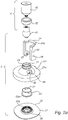
- FIG 2a and 2b show the radar level arrangement 2 in figure 1 in more detail.
- the suction cup 3 here comprises a main body 21 and an annular bellows 22.
- the main body 21 includes a substantially bell-shaped outer portion 31, and an inner, substantially cylindrical portion 32.
- the outer perimeter 33 of the outer portion 31, and the lower edge 34 of the cylindrical portion 32 are here coaxial ring-shaped surfaces substantially in the same geometric attachment plane.
- the width d of these ring shaped surfaces may be at least three mm, and preferably at least five mm.
- Between the cylindrical portion 32 and the bell-shaped portion 31 is formed an interior space 35 delimited by the plane.
- the annular bellows 22 is arranged substantially in this plane, with its inner perimeter 36 aligned with the edge 34 and its outer perimeter 37 aligned with the perimeter 33.
- the suction cup 3 further comprises a sleeve 23, coaxially arranged around the cylindrical portion 32 and axially movable in the space 35.
- the lower edge 23a of the sleeve 23 is operatively attached to an intermediate part 22a of the bellows 22, i.e. a part between the inner perimeter 36 and the outer perimeter 37.
- the sleeve 23 is further operatively linked to a lever 24 so as to be axially displaced by rotation of the lever 24. Displacement of the sleeve 23 will in turn lift the intermediate part 22a of the bellows 22 that is attached to the sleeve 23.
- operatively attached is here intended to indicate that the bellows 22 will be mechanically operated when the sleeve 23 is moved.
- the sleeve can be fixedly attached, e.g. by welding, vulcanization or glue, to the bellows 22.
- the bellows can be otherwise mechanically engaged, e.g. by engaging the lower edge of the sleeve, which then preferably is protruding as indicated in figure 2a and 2b .
- the lever 24 is U-shaped, and each leg 26 is operatively connected to the sleeve 23 by means of a pin 25 extending through an opening 30 in the body 21.
- the pin 25 can for example be fixed to the leg 26 and extend into a hole 27 in each side of the sleeve 23.
- Each leg 26 of the lever 24 is further provided with a cam 28 that interacts with an abutment surface 29 of the main body, such that, when the lever is turned, both pins 25 will be forced upwards (away from the bellows 22) and bring the sleeve 23 along with it.
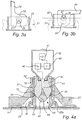
- lever 24 Operation of the lever 24 is shown in more detail in figure 3a and 3b .
- the lever 24 is in an upright position, and the sleeve 23 is in a first, lowered position.
- the cam surface 28 will slide against the abutment surface 29, thereby forcing the pin 25 upwards, away from the abutment surface, bringing the sleeve 23 along with it.
- the lever 24 as reached its end position, level with the upper surface of the body 21.
- the body 21 has a recess 21 a configured to receive the end portion 24a of the lever 24, thereby stabilizing the lever 24 in this end position.
- the sleeve 23 has been moved to a second, raised position.
- references such as “lowered” and “raised” are used with reference to the surface onto which the attachment device 3 is placed. If the attachment device is placed on an inclined surface, the movement of the sleeve 23 will not be vertical, as indicated in figure 3a-b .
- Figure 4a and 4b show the radar level gauging arrangement 2 placed with the bellows 22 of the suction cup 3 against a tank wall 5.
- the inner perimeter 36 of the bellows will be sandwiched between the tank wall 5 and the lower edge 34 of the cylindrical portion 32.
- the outer perimeter of the bellows 37 will be sandwiched between the tank wall 5 and the outer perimeter 33 of the bell-shaped portion 31.
- Ambient air is thus prevented from entering the compartment 38, and as the sleeve 23 is lifted and the volume of the compartment 38 increases, the pressure in the compartment 38 will therefore fall below the ambient pressure. A partial vacuum is thus formed in the compartment 38, effectively securing the suction cup 3 to the tank wall 5.
- the material and thickness of the bellows 22 is selected such that the compartment 38 is effectively sealed from the ambient, in order to maintain the partial vacuum as long as possible. Further, the width of the ring-shaped surfaces 33 and 34 that press on the bellows 22 is chosen to compensate for minor unevenness in the tank wall surface. As an example, the width of these surfaces can be around 5 mm.
- the surface of the tank wall 5 may be treated to make it as smooth as possible, before mounting the suction cup 3.
- the surface may be heated, polished or otherwise smoothed.
- the outer perimeter 37 and/or the inner perimeter 36 of the bellows may be provided with an adhesive which is activated by pressure.
- the suction provided by the partial vacuum in compartment 38 will serve to apply pressure on the adhesive, thereby adhesively attaching the bellows 22 to the tank wall 5.
- the adhesive attachment will maintain the partial vacuum even longer. Further, even if the partial vacuum in compartment 38 eventually deteriorates, the bellows 22 - and the suction cup 3 - will remain secured to the tank wall 5 by means of adhesion.
- the radar level gauge 4 comprises a waveguide portion 41 and a housing 42 mechanically fixed to the waveguide portion 41.
- the waveguide portion 41 forms a waveguide 43 extending between a directional antenna 44 arranged on the lower side of the waveguide portion, and transceiver circuitry 45 arranged in the housing 42.
- the housing also includes processing circuitry 46, and any I/O circuitry 47 required.
- the waveguide portion is a solid piece of electrically conducting material, e.g. metal, and the waveguide 43 and antenna horn 48 are formed directly in this solid piece.
- the waveguide portion is made of a non-conducting rigid material, e.g. a ceramic material, and the waveguide 43 and antenna 44 are formed by electrically conducting members inserted into the portion 41. In principle, such members may simply be an electrically conducting coating on the inside of the portion 41.
- the antenna horn 48 is preferably filled with a dielectric filling member 49, which is sealed against the inside of the waveguide portion 41.
- a dielectric filling member 49 which is sealed against the inside of the waveguide portion 41.
- the RLG 4 is pivotly arranged in the cylindrical portion 32 of the main body 21.
- the waveguide portion 41 has a generally spherical shape, and is arranged to rest against an abutment 51 in the cylindrical portion 32.
- a fastening member here an annular ring 52, is attached, e.g. snap fitted, to the upper edge 53 of the main body 21, so that the spherical waveguide portion 41 is sandwiched between the abutment 51 and the ring 52.
- the abutment 51 is preferably provided with a grove 54, wherein a suitable sealing element 55, such as an O-ring, can be arranged.
- the radar level gauge 4 can be pivoted to ensure that the antenna 48 can emit signals normal to the surface 6 in the tank 1.
- this in practice corresponds to orienting the radar level gauge 4 with its longitudinal axis vertical.
- the antenna is arranged to emit radar signals through the central opening of the bellows 21. It is noted that many materials that are suitable for the bellows will block or attenuate radar signals, and the central opening is therefore advantageous. However, if the bellows is made of a material which is transmissive to radar signals, then the bellows does not necessarily have a central opening.
- FIG. 5 shows a further embodiment of the invention.
- the arrangement 102 here includes a suction cup 103 secured to a tank wall 105, and a radar level gauge 104 which is asymmetrically mounted with respect to the suction cup 103 by means of a mechanical structure 110.
- the suction cup here includes a cup shaped body 121, and a cup shaped bellows 122 attached to the inside of the cup to form an air tight inner lining.
- the upper part of the bellows 122 has an annular recess 123 which is engaged with a flange124 in the upper part of the body 121.
- the outer perimeter 137 of the bellows is sandwiched between the lower rim 133 of the body 121 facing the tank wall.
- the bellows 122 is attached to the body 121 e.g. by welding, vulcanization or adhesion.
- the entire bellows 122 is adhesively attached (or laminated) to the inside of the body 121.
- Such a laminated suction cup may potentially support a greater vacuum and thus stronger attachment.
- a flexible bellows as illustrated in figure 5 , may be more forgiving to unevenness in the tank wall.
- the partial vacuum is not provided by displacement of the bellows.
- a source 130 of sub-atmospheric pressure is connected to a connection terminal 131 in the body.
- the connection terminal provides fluid access to the compartment 138 formed between the bellows 122 and the tank wall 105.
- the source of sub-atmospheric pressure here a vacuum pump 130, creates a partial vacuum in the compartment 138, thereby securing the suction cup 103 to the tank wall 105.
- the terminal 131 may be provided with a pressure valve 132, preventing ambient air to enter the compartment 138.
- the source 130 may then be disconnected from the terminal 131 without releasing the suction cup 103 from the tank wall 105.
- the mechanical structure 110 here includes a hinge 107 having a first end 107a mounted to the body 121 of the suction cup, and a second end 107b mounted to the radar level gauge 104.
- the hinge 107 allows alignment of the RLG, such that the signals emitted by the RLG are essentially normal to the product surface 106. It is noted that the hinge 107 may not be required in all applications.
- Figure 6 shows yet another embodiment, where the arrangement includes two suctions cups 203, and the RLG 204 is mounted on a structure 210 mounted to the body 221 of each suction cup 203 and extending between them.
- the RLG 204 is pivotably mounted in a manner similar to that disclosed in figure 4a-b above.
- the suction cups 203 are here more conventional suction cups, of the type used e.g. for glass handles, and will only be briefly described herein.
- Each suction cup includes a bell-shaped body 221 and a bellows 222 arranged therein.
- a handle 223 is operable to move a central part of the bellows away from the tank wall 205, thereby increasing the volume of a compartment between the bellows 222 and the tank wall 205.
- suction cups may be preferably to have more than two suction cups, e.g. three suction cups or four suction cups.
- the bellows is not necessarily annular, i.e. be formed without a central opening.
- the radar level gauge may be mounted displaced from the suction device instead of being centrally mounted as in the above embodiment.
Landscapes
- Physics & Mathematics (AREA)
- Engineering & Computer Science (AREA)
- Radar, Positioning & Navigation (AREA)
- Remote Sensing (AREA)
- General Physics & Mathematics (AREA)
- Electromagnetism (AREA)
- Fluid Mechanics (AREA)
- General Engineering & Computer Science (AREA)
- Computer Networks & Wireless Communication (AREA)
- Thermal Sciences (AREA)
- Mechanical Engineering (AREA)
- Measurement Of Levels Of Liquids Or Fluent Solid Materials (AREA)
Applications Claiming Priority (1)
| Application Number | Priority Date | Filing Date | Title |
|---|---|---|---|
| US15/481,789 US10725160B2 (en) | 2017-04-07 | 2017-04-07 | Non-invasive radar level gauge |
Publications (2)
| Publication Number | Publication Date |
|---|---|
| EP3385682A1 true EP3385682A1 (de) | 2018-10-10 |
| EP3385682B1 EP3385682B1 (de) | 2023-09-27 |
Family
ID=61837689
Family Applications (1)
| Application Number | Title | Priority Date | Filing Date |
|---|---|---|---|
| EP18164946.8A Active EP3385682B1 (de) | 2017-04-07 | 2018-03-29 | Nichtinvasives radarfüllstandmessgerät |
Country Status (3)
| Country | Link |
|---|---|
| US (1) | US10725160B2 (de) |
| EP (1) | EP3385682B1 (de) |
| CN (2) | CN108689035B (de) |
Cited By (5)
| Publication number | Priority date | Publication date | Assignee | Title |
|---|---|---|---|---|
| WO2021165107A1 (de) * | 2020-02-17 | 2021-08-26 | Vega Grieshaber Kg | Schutzvorrichtung zur abdichtung einer sensorvorrichtung |
| EP3885717A1 (de) * | 2020-03-25 | 2021-09-29 | VEGA Grieshaber KG | Messanordnung zur befestigung an einem behältnis |
| WO2022008076A1 (de) * | 2020-07-10 | 2022-01-13 | Vega Grieshaber Kg | Messanordnung zur anbringung an einem deckel eines behältnisses |
| EP4040117A1 (de) * | 2021-02-05 | 2022-08-10 | VEGA Grieshaber KG | Messgerät mit flexibler befestigungseinrichtung |
| WO2024231151A1 (de) * | 2023-05-11 | 2024-11-14 | Vega Grieshaber Kg | Messanordnung eines feldgeräts an einem behälter |
Families Citing this family (11)
| Publication number | Priority date | Publication date | Assignee | Title |
|---|---|---|---|---|
| US10725160B2 (en) * | 2017-04-07 | 2020-07-28 | Rosemount Tank Radar Ab | Non-invasive radar level gauge |
| EP3736545B1 (de) * | 2019-05-09 | 2023-04-19 | VEGA Grieshaber KG | Füllstandsmesseinrichtung |
| EP3748312B1 (de) * | 2019-06-07 | 2022-06-01 | VEGA Grieshaber KG | Messgerät mit flansch und behälter mit diesem messgerät |
| US11280659B2 (en) * | 2019-08-23 | 2022-03-22 | Endress+Hauser SE+Co. KG | Reflector for radar-based fill level detection |
| DE102019128582A1 (de) * | 2019-10-23 | 2021-04-29 | Vega Grieshaber Kg | Radarmessgerät und Anordnung eines Radarmessgeräts an einem Behälter |
| DE102020100867A1 (de) * | 2020-01-15 | 2021-07-15 | Endress+Hauser SE+Co. KG | Befestigungs-Vorrichtung für Füllstandsmessgeräte |
| EP4158289B1 (de) * | 2020-05-29 | 2025-04-23 | VEGA Grieshaber KG | Optisches füllstandmessgerät |
| EP4170298B1 (de) * | 2021-10-21 | 2025-08-20 | VEGA Grieshaber KG | Radarmessgerät, messanordnung und linse |
| CN114216498B (zh) * | 2021-11-19 | 2024-12-13 | 领翌技术(横琴)有限公司 | Ibc桶状态检测装置 |
| DE102022103827A1 (de) | 2022-02-17 | 2023-08-17 | Vega Grieshaber Kg | Messanordnung eines Sensors und Behalters, Montagehalterung sowie Verfahren zur Montage eines Sensors an einem Behälter |
| EP4266013A1 (de) * | 2022-04-20 | 2023-10-25 | Rosemount Tank Radar AB | Radarfüllstandsmesssystem mit einer antennenanordnung mit einem nichtplastischen dielektrischen antennenkörper |
Citations (5)
| Publication number | Priority date | Publication date | Assignee | Title |
|---|---|---|---|---|
| JPH10234734A (ja) * | 1996-12-27 | 1998-09-08 | Nohmi Bosai Ltd | 超音波プローブ |
| GB2438626A (en) * | 2006-05-31 | 2007-12-05 | Northstar Systems Corp | Suction disc apparatus |
| US20090193888A1 (en) * | 2008-02-01 | 2009-08-06 | Josh Rayner | Non-Contact Radar Based Level Measurement Device |
| US20130228011A1 (en) * | 2012-03-01 | 2013-09-05 | Krohne Messtechnik Gmbh | Microwave window and fill level sensor using the radar principle |
| US20160025264A1 (en) * | 2006-03-03 | 2016-01-28 | Charles L. Casagrande | Mounting system and accessory components |
Family Cites Families (43)
| Publication number | Priority date | Publication date | Assignee | Title |
|---|---|---|---|---|
| US3748637A (en) * | 1971-10-22 | 1973-07-24 | C W S Ind Inc | Sonar transducer assembly |
| US4044355A (en) * | 1973-11-20 | 1977-08-23 | Saab-Scania Aktiebolag | Measurement of contents of tanks etc. with microwave radiations |
| US4107993A (en) * | 1975-12-29 | 1978-08-22 | Monsanto Company | Method and apparatus for level measurement using microwaves |
| GB2020507B (en) * | 1978-02-24 | 1982-04-28 | Hawker Siddeley Dynamics Eng | Method and apparatus for measurement of the contents of a bunker or silo |
| LU80645A1 (fr) * | 1978-12-12 | 1979-04-09 | Wurth Anciens Ets Paul | Dispositif de montage d'une sonde radar pour fours a cuve |
| US4205315A (en) * | 1979-02-12 | 1980-05-27 | Manning Environmental Corp. | Fluid level measurement apparatus for mounting in manholes and similar structures |
| US4269383A (en) * | 1979-02-23 | 1981-05-26 | The United States Of America As Represented By The Secretary Of The Navy | Suction cup with lateral gripper |
| LU81158A1 (fr) * | 1979-04-13 | 1979-06-19 | Wurth Paul Sa | Dispositif de montage d'une sonde radar pour fours a cuve |
| SE441306B (sv) * | 1984-04-25 | 1985-09-23 | Saab Marine Electronics | Sett och anordning for metning av nivan hos ett i en behallare forvarat flytande material |
| US4566321A (en) * | 1985-01-18 | 1986-01-28 | Transamerica Delaval Inc. | Microwave tank-contents level measuring assembly with lens-obturated wall-opening |
| US4833918A (en) * | 1986-09-24 | 1989-05-30 | Cannonbear, Inc. | Sensor and method for ullage level and flow detection |
| GB9008764D0 (en) * | 1990-04-19 | 1990-06-13 | Egnell Ameda Ltd | A resilient suction cup |
| US5351036A (en) * | 1991-12-10 | 1994-09-27 | Clark-Reliance Corporation | Microwave-based point liquid level monitoring system |
| DE4336494C2 (de) * | 1993-10-26 | 1995-11-02 | Endress Hauser Gmbh Co | Vorrichtung zur Füllstandsmessung in Behältern |
| US5438868A (en) * | 1993-11-01 | 1995-08-08 | Zevex, Inc. | Noninvasive ultrasonic liquid level indicator |
| US5507181A (en) * | 1993-12-27 | 1996-04-16 | Motorola, Inc. | Non-intrusive mounting system and method for microwave instruments |
| US6192752B1 (en) * | 1995-08-04 | 2001-02-27 | Zevex, Inc. | Noninvasive electromagnetic fluid level sensor |
| US5767407A (en) * | 1996-01-23 | 1998-06-16 | The Regents Of The University Of California | Noninvasive identification of fluids by swept-frequency acoustic interferometry |
| EP1070941A1 (de) * | 1999-07-23 | 2001-01-24 | Endress + Hauser GmbH + Co. | Vorrichtung zum Messen des Füllstandes in einem Behälter |
| US7216536B2 (en) * | 2001-06-22 | 2007-05-15 | Young Manufacturing & Engineering, Inc. | Acoustic volume indicator |
| US7114390B2 (en) * | 2003-02-14 | 2006-10-03 | Adept Science & Technologies, Llc | Ultrasonic liquid level monitor |
| DE102004033033A1 (de) * | 2004-07-07 | 2006-02-09 | Vega Grieshaber Kg | Füllstandsmessungs-Antennenanordnung für Radar-Füllstandsmessgeräte |
| CN2733070Y (zh) * | 2004-10-20 | 2005-10-12 | 范裕雄 | 吸盘装置 |
| US7173436B2 (en) * | 2004-11-24 | 2007-02-06 | Saab Rosemount Tank Radar Ag | Antenna device for level gauging |
| DE102005049242B4 (de) * | 2005-10-14 | 2008-01-24 | Vega Grieshaber Kg | Parabolantenne mit konischer Streuscheibe für Füllstandradar |
| US20070180903A1 (en) * | 2006-02-09 | 2007-08-09 | Alcon, Inc. | Acoustic fluid level sensor |
| US7784341B2 (en) * | 2006-04-19 | 2010-08-31 | Peter C Blokhuis | Liquid monitoring apparatus and method of using same for containers |
| US7898496B2 (en) | 2006-06-05 | 2011-03-01 | Eric Olsen | Antenna mount with alternative uses |
| JP4926690B2 (ja) * | 2006-12-20 | 2012-05-09 | 株式会社アイ・アンド・ティー | ワーク吸着装置 |
| TW200908437A (en) * | 2007-08-10 | 2009-02-16 | Yuan High Tech Dev Co Ltd | Digital antenna device |
| WO2009026672A1 (en) | 2007-08-30 | 2009-03-05 | Sensotech Inc. | Level sensor system for propane tanks and or the likes |
| CN101169662A (zh) * | 2007-12-03 | 2008-04-30 | 西安华舜测量设备有限责任公司 | 一种外置式超声波液位监控报警装置 |
| US8069722B1 (en) * | 2008-06-09 | 2011-12-06 | L&J Engineering, Inc. | Tank gage hatch assembly |
| US8482295B2 (en) * | 2009-02-23 | 2013-07-09 | Hatch Ltd. | Electromagnetic bath level measurement for pyrometallurgical furnaces |
| CN101762305A (zh) * | 2009-12-28 | 2010-06-30 | 厦门大学 | 外挂式液位报警仪 |
| DE102010005540A1 (de) * | 2010-01-23 | 2011-07-28 | hansaconsult Ingenieurgesellschaft mbH, 21465 | Vorrichtung und Verfahren zur Füllstandsmessung in einem Tank mit flexiblen Wänden |
| US8350751B2 (en) * | 2010-03-10 | 2013-01-08 | Rosemount Tank Radar Ab | Radar level gauge with improved radar window |
| CN102011788B (zh) * | 2010-11-19 | 2012-10-10 | 黄明达 | 弹性复位吸盘 |
| DE202011110687U1 (de) | 2011-08-19 | 2015-07-27 | Truma Gerätetechnik GmbH & Co. KG | Mobiles Messgerät zur Füllbestandsbestimmung bei Behältern aller Art |
| TWI502141B (zh) * | 2012-12-20 | 2015-10-01 | Wistron Corp | 吸盤模組及應用該吸盤模組之電子裝置 |
| DE102013112025A1 (de) | 2013-10-31 | 2015-04-30 | Endress + Hauser Gmbh + Co. Kg | Vorrichtung zur Bestimmung oder Überwachung des Füllstands eines Mediums in einem Behälter |
| DE102015113908B4 (de) * | 2015-08-21 | 2023-05-04 | Truma Gerätetechnik GmbH & Co. KG | Füllstandsmessgerät |
| US10725160B2 (en) * | 2017-04-07 | 2020-07-28 | Rosemount Tank Radar Ab | Non-invasive radar level gauge |
-
2017
- 2017-04-07 US US15/481,789 patent/US10725160B2/en active Active
- 2017-06-05 CN CN201710413821.1A patent/CN108689035B/zh active Active
- 2017-06-05 CN CN201720657188.6U patent/CN207329364U/zh active Active
-
2018
- 2018-03-29 EP EP18164946.8A patent/EP3385682B1/de active Active
Patent Citations (5)
| Publication number | Priority date | Publication date | Assignee | Title |
|---|---|---|---|---|
| JPH10234734A (ja) * | 1996-12-27 | 1998-09-08 | Nohmi Bosai Ltd | 超音波プローブ |
| US20160025264A1 (en) * | 2006-03-03 | 2016-01-28 | Charles L. Casagrande | Mounting system and accessory components |
| GB2438626A (en) * | 2006-05-31 | 2007-12-05 | Northstar Systems Corp | Suction disc apparatus |
| US20090193888A1 (en) * | 2008-02-01 | 2009-08-06 | Josh Rayner | Non-Contact Radar Based Level Measurement Device |
| US20130228011A1 (en) * | 2012-03-01 | 2013-09-05 | Krohne Messtechnik Gmbh | Microwave window and fill level sensor using the radar principle |
Cited By (7)
| Publication number | Priority date | Publication date | Assignee | Title |
|---|---|---|---|---|
| WO2021165107A1 (de) * | 2020-02-17 | 2021-08-26 | Vega Grieshaber Kg | Schutzvorrichtung zur abdichtung einer sensorvorrichtung |
| CN115104006A (zh) * | 2020-02-17 | 2022-09-23 | Vega格里沙贝两合公司 | 用于密封传感器装置的保护装置 |
| US12693374B2 (en) | 2020-02-17 | 2026-07-28 | Vega Grieshaber Kg | Protection device for sealing a sensor device |
| EP3885717A1 (de) * | 2020-03-25 | 2021-09-29 | VEGA Grieshaber KG | Messanordnung zur befestigung an einem behältnis |
| WO2022008076A1 (de) * | 2020-07-10 | 2022-01-13 | Vega Grieshaber Kg | Messanordnung zur anbringung an einem deckel eines behältnisses |
| EP4040117A1 (de) * | 2021-02-05 | 2022-08-10 | VEGA Grieshaber KG | Messgerät mit flexibler befestigungseinrichtung |
| WO2024231151A1 (de) * | 2023-05-11 | 2024-11-14 | Vega Grieshaber Kg | Messanordnung eines feldgeräts an einem behälter |
Also Published As
| Publication number | Publication date |
|---|---|
| US20180292519A1 (en) | 2018-10-11 |
| EP3385682B1 (de) | 2023-09-27 |
| CN207329364U (zh) | 2018-05-08 |
| US10725160B2 (en) | 2020-07-28 |
| CN108689035A (zh) | 2018-10-23 |
| CN108689035B (zh) | 2022-10-04 |
Similar Documents
| Publication | Publication Date | Title |
|---|---|---|
| US10725160B2 (en) | Non-invasive radar level gauge | |
| US7762428B2 (en) | Emptying device | |
| US10335792B2 (en) | Reagent bottle cap, system, method and apparatus for handling closure caps and like | |
| JP5180001B2 (ja) | センサを備える液体化学薬品分配システム | |
| EP3529569B1 (de) | Radarfüllstandsmesser mit hochtemperatur-hochdruck (hthp)-prozessdichtung | |
| CN104108529B (zh) | 饮 料 用 容 器 | |
| JP6900136B2 (ja) | ウエハ位置検出装置を有する気相腐食キャビティ | |
| EP2972136B1 (de) | Hochtemperatur- und hochdruck-radarfüllstandsmessvorrichtung | |
| US7048136B2 (en) | Canister lid with improved evacuation and vent assembly | |
| US3540856A (en) | Sample capsule and filtering mechanism | |
| EP1880947A3 (de) | Behälter, Ausgabevorrichtung und Verfahren zur Ausgabe von Waren | |
| CA2835267A1 (en) | Device and method for draining and rinsing containers filled with fluid | |
| CN102686506A (zh) | 具有接头加装件的一次性容器 | |
| EP3137213B1 (de) | Verschluss für eine reagenzienflasche, system und verfahren zur handhabung von verschlusskappen und dergleichen | |
| TWI913305B (zh) | 開閉構件 | |
| KR101647090B1 (ko) | 원료 혼합장치 | |
| CN219720379U (zh) | 内锅及具有其的烹饪器具 | |
| US12460960B2 (en) | Measuring device, attachment system, measuring assembly and method | |
| KR102523951B1 (ko) | 폴라이트 패킹 자동 부착장치 | |
| CN212606515U (zh) | 一种水桶 | |
| US10961034B2 (en) | Outlet connector piece having a protruding flange | |
| CN211582586U (zh) | 烹饪器具 | |
| JPH018544Y2 (de) | ||
| JPH0486250A (ja) | 液体注出口取付装置 | |
| WO2014148601A1 (ja) | 二段反応システム、試料液の測定システム、および試料液の測定方法 |
Legal Events
| Date | Code | Title | Description |
|---|---|---|---|
| PUAI | Public reference made under article 153(3) epc to a published international application that has entered the european phase |
Free format text: ORIGINAL CODE: 0009012 |
|
| STAA | Information on the status of an ep patent application or granted ep patent |
Free format text: STATUS: THE APPLICATION HAS BEEN PUBLISHED |
|
| AK | Designated contracting states |
Kind code of ref document: A1 Designated state(s): AL AT BE BG CH CY CZ DE DK EE ES FI FR GB GR HR HU IE IS IT LI LT LU LV MC MK MT NL NO PL PT RO RS SE SI SK SM TR |
|
| AX | Request for extension of the european patent |
Extension state: BA ME |
|
| STAA | Information on the status of an ep patent application or granted ep patent |
Free format text: STATUS: REQUEST FOR EXAMINATION WAS MADE |
|
| 17P | Request for examination filed |
Effective date: 20190109 |
|
| RBV | Designated contracting states (corrected) |
Designated state(s): AL AT BE BG CH CY CZ DE DK EE ES FI FR GB GR HR HU IE IS IT LI LT LU LV MC MK MT NL NO PL PT RO RS SE SI SK SM TR |
|
| STAA | Information on the status of an ep patent application or granted ep patent |
Free format text: STATUS: EXAMINATION IS IN PROGRESS |
|
| 17Q | First examination report despatched |
Effective date: 20190819 |
|
| GRAP | Despatch of communication of intention to grant a patent |
Free format text: ORIGINAL CODE: EPIDOSNIGR1 |
|
| STAA | Information on the status of an ep patent application or granted ep patent |
Free format text: STATUS: GRANT OF PATENT IS INTENDED |
|
| INTG | Intention to grant announced |
Effective date: 20230420 |
|
| GRAS | Grant fee paid |
Free format text: ORIGINAL CODE: EPIDOSNIGR3 |
|
| GRAA | (expected) grant |
Free format text: ORIGINAL CODE: 0009210 |
|
| STAA | Information on the status of an ep patent application or granted ep patent |
Free format text: STATUS: THE PATENT HAS BEEN GRANTED |
|
| AK | Designated contracting states |
Kind code of ref document: B1 Designated state(s): AL AT BE BG CH CY CZ DE DK EE ES FI FR GB GR HR HU IE IS IT LI LT LU LV MC MK MT NL NO PL PT RO RS SE SI SK SM TR |
|
| REG | Reference to a national code |
Ref country code: GB Ref legal event code: FG4D |
|
| REG | Reference to a national code |
Ref country code: CH Ref legal event code: EP |
|
| REG | Reference to a national code |
Ref country code: DE Ref legal event code: R096 Ref document number: 602018058139 Country of ref document: DE |
|
| REG | Reference to a national code |
Ref country code: IE Ref legal event code: FG4D |
|
| REG | Reference to a national code |
Ref country code: LT Ref legal event code: MG9D |
|
| PG25 | Lapsed in a contracting state [announced via postgrant information from national office to epo] |
Ref country code: GR Free format text: LAPSE BECAUSE OF FAILURE TO SUBMIT A TRANSLATION OF THE DESCRIPTION OR TO PAY THE FEE WITHIN THE PRESCRIBED TIME-LIMIT Effective date: 20231228 |
|
| PG25 | Lapsed in a contracting state [announced via postgrant information from national office to epo] |
Ref country code: SE Free format text: LAPSE BECAUSE OF FAILURE TO SUBMIT A TRANSLATION OF THE DESCRIPTION OR TO PAY THE FEE WITHIN THE PRESCRIBED TIME-LIMIT Effective date: 20230927 Ref country code: RS Free format text: LAPSE BECAUSE OF FAILURE TO SUBMIT A TRANSLATION OF THE DESCRIPTION OR TO PAY THE FEE WITHIN THE PRESCRIBED TIME-LIMIT Effective date: 20230927 Ref country code: NO Free format text: LAPSE BECAUSE OF FAILURE TO SUBMIT A TRANSLATION OF THE DESCRIPTION OR TO PAY THE FEE WITHIN THE PRESCRIBED TIME-LIMIT Effective date: 20231227 Ref country code: LV Free format text: LAPSE BECAUSE OF FAILURE TO SUBMIT A TRANSLATION OF THE DESCRIPTION OR TO PAY THE FEE WITHIN THE PRESCRIBED TIME-LIMIT Effective date: 20230927 Ref country code: LT Free format text: LAPSE BECAUSE OF FAILURE TO SUBMIT A TRANSLATION OF THE DESCRIPTION OR TO PAY THE FEE WITHIN THE PRESCRIBED TIME-LIMIT Effective date: 20230927 Ref country code: HR Free format text: LAPSE BECAUSE OF FAILURE TO SUBMIT A TRANSLATION OF THE DESCRIPTION OR TO PAY THE FEE WITHIN THE PRESCRIBED TIME-LIMIT Effective date: 20230927 Ref country code: GR Free format text: LAPSE BECAUSE OF FAILURE TO SUBMIT A TRANSLATION OF THE DESCRIPTION OR TO PAY THE FEE WITHIN THE PRESCRIBED TIME-LIMIT Effective date: 20231228 Ref country code: FI Free format text: LAPSE BECAUSE OF FAILURE TO SUBMIT A TRANSLATION OF THE DESCRIPTION OR TO PAY THE FEE WITHIN THE PRESCRIBED TIME-LIMIT Effective date: 20230927 |
|
| REG | Reference to a national code |
Ref country code: NL Ref legal event code: MP Effective date: 20230927 |
|
| REG | Reference to a national code |
Ref country code: AT Ref legal event code: MK05 Ref document number: 1615823 Country of ref document: AT Kind code of ref document: T Effective date: 20230927 |
|
| PG25 | Lapsed in a contracting state [announced via postgrant information from national office to epo] |
Ref country code: NL Free format text: LAPSE BECAUSE OF FAILURE TO SUBMIT A TRANSLATION OF THE DESCRIPTION OR TO PAY THE FEE WITHIN THE PRESCRIBED TIME-LIMIT Effective date: 20230927 |
|
| PG25 | Lapsed in a contracting state [announced via postgrant information from national office to epo] |
Ref country code: IS Free format text: LAPSE BECAUSE OF FAILURE TO SUBMIT A TRANSLATION OF THE DESCRIPTION OR TO PAY THE FEE WITHIN THE PRESCRIBED TIME-LIMIT Effective date: 20240127 |
|
| PG25 | Lapsed in a contracting state [announced via postgrant information from national office to epo] |
Ref country code: AT Free format text: LAPSE BECAUSE OF FAILURE TO SUBMIT A TRANSLATION OF THE DESCRIPTION OR TO PAY THE FEE WITHIN THE PRESCRIBED TIME-LIMIT Effective date: 20230927 |
|
| PG25 | Lapsed in a contracting state [announced via postgrant information from national office to epo] |
Ref country code: ES Free format text: LAPSE BECAUSE OF FAILURE TO SUBMIT A TRANSLATION OF THE DESCRIPTION OR TO PAY THE FEE WITHIN THE PRESCRIBED TIME-LIMIT Effective date: 20230927 |
|
| PG25 | Lapsed in a contracting state [announced via postgrant information from national office to epo] |
Ref country code: SM Free format text: LAPSE BECAUSE OF FAILURE TO SUBMIT A TRANSLATION OF THE DESCRIPTION OR TO PAY THE FEE WITHIN THE PRESCRIBED TIME-LIMIT Effective date: 20230927 Ref country code: RO Free format text: LAPSE BECAUSE OF FAILURE TO SUBMIT A TRANSLATION OF THE DESCRIPTION OR TO PAY THE FEE WITHIN THE PRESCRIBED TIME-LIMIT Effective date: 20230927 Ref country code: IS Free format text: LAPSE BECAUSE OF FAILURE TO SUBMIT A TRANSLATION OF THE DESCRIPTION OR TO PAY THE FEE WITHIN THE PRESCRIBED TIME-LIMIT Effective date: 20240127 Ref country code: ES Free format text: LAPSE BECAUSE OF FAILURE TO SUBMIT A TRANSLATION OF THE DESCRIPTION OR TO PAY THE FEE WITHIN THE PRESCRIBED TIME-LIMIT Effective date: 20230927 Ref country code: EE Free format text: LAPSE BECAUSE OF FAILURE TO SUBMIT A TRANSLATION OF THE DESCRIPTION OR TO PAY THE FEE WITHIN THE PRESCRIBED TIME-LIMIT Effective date: 20230927 Ref country code: CZ Free format text: LAPSE BECAUSE OF FAILURE TO SUBMIT A TRANSLATION OF THE DESCRIPTION OR TO PAY THE FEE WITHIN THE PRESCRIBED TIME-LIMIT Effective date: 20230927 Ref country code: AT Free format text: LAPSE BECAUSE OF FAILURE TO SUBMIT A TRANSLATION OF THE DESCRIPTION OR TO PAY THE FEE WITHIN THE PRESCRIBED TIME-LIMIT Effective date: 20230927 Ref country code: SK Free format text: LAPSE BECAUSE OF FAILURE TO SUBMIT A TRANSLATION OF THE DESCRIPTION OR TO PAY THE FEE WITHIN THE PRESCRIBED TIME-LIMIT Effective date: 20230927 Ref country code: PT Free format text: LAPSE BECAUSE OF FAILURE TO SUBMIT A TRANSLATION OF THE DESCRIPTION OR TO PAY THE FEE WITHIN THE PRESCRIBED TIME-LIMIT Effective date: 20240129 |
|
| PG25 | Lapsed in a contracting state [announced via postgrant information from national office to epo] |
Ref country code: PL Free format text: LAPSE BECAUSE OF FAILURE TO SUBMIT A TRANSLATION OF THE DESCRIPTION OR TO PAY THE FEE WITHIN THE PRESCRIBED TIME-LIMIT Effective date: 20230927 Ref country code: IT Free format text: LAPSE BECAUSE OF FAILURE TO SUBMIT A TRANSLATION OF THE DESCRIPTION OR TO PAY THE FEE WITHIN THE PRESCRIBED TIME-LIMIT Effective date: 20230927 |
|
| REG | Reference to a national code |
Ref country code: DE Ref legal event code: R097 Ref document number: 602018058139 Country of ref document: DE |
|
| PG25 | Lapsed in a contracting state [announced via postgrant information from national office to epo] |
Ref country code: DK Free format text: LAPSE BECAUSE OF FAILURE TO SUBMIT A TRANSLATION OF THE DESCRIPTION OR TO PAY THE FEE WITHIN THE PRESCRIBED TIME-LIMIT Effective date: 20230927 |
|
| PG25 | Lapsed in a contracting state [announced via postgrant information from national office to epo] |
Ref country code: DK Free format text: LAPSE BECAUSE OF FAILURE TO SUBMIT A TRANSLATION OF THE DESCRIPTION OR TO PAY THE FEE WITHIN THE PRESCRIBED TIME-LIMIT Effective date: 20230927 |
|
| PLBE | No opposition filed within time limit |
Free format text: ORIGINAL CODE: 0009261 |
|
| STAA | Information on the status of an ep patent application or granted ep patent |
Free format text: STATUS: NO OPPOSITION FILED WITHIN TIME LIMIT |
|
| 26N | No opposition filed |
Effective date: 20240628 |
|
| PG25 | Lapsed in a contracting state [announced via postgrant information from national office to epo] |
Ref country code: SI Free format text: LAPSE BECAUSE OF FAILURE TO SUBMIT A TRANSLATION OF THE DESCRIPTION OR TO PAY THE FEE WITHIN THE PRESCRIBED TIME-LIMIT Effective date: 20230927 |
|
| PG25 | Lapsed in a contracting state [announced via postgrant information from national office to epo] |
Ref country code: SI Free format text: LAPSE BECAUSE OF FAILURE TO SUBMIT A TRANSLATION OF THE DESCRIPTION OR TO PAY THE FEE WITHIN THE PRESCRIBED TIME-LIMIT Effective date: 20230927 |
|
| PG25 | Lapsed in a contracting state [announced via postgrant information from national office to epo] |
Ref country code: BG Free format text: LAPSE BECAUSE OF FAILURE TO SUBMIT A TRANSLATION OF THE DESCRIPTION OR TO PAY THE FEE WITHIN THE PRESCRIBED TIME-LIMIT Effective date: 20230927 |
|
| PG25 | Lapsed in a contracting state [announced via postgrant information from national office to epo] |
Ref country code: LU Free format text: LAPSE BECAUSE OF NON-PAYMENT OF DUE FEES Effective date: 20240329 |
|
| PG25 | Lapsed in a contracting state [announced via postgrant information from national office to epo] |
Ref country code: MC Free format text: LAPSE BECAUSE OF FAILURE TO SUBMIT A TRANSLATION OF THE DESCRIPTION OR TO PAY THE FEE WITHIN THE PRESCRIBED TIME-LIMIT Effective date: 20230927 |
|
| GBPC | Gb: european patent ceased through non-payment of renewal fee |
Effective date: 20240329 |
|
| PG25 | Lapsed in a contracting state [announced via postgrant information from national office to epo] |
Ref country code: MC Free format text: LAPSE BECAUSE OF FAILURE TO SUBMIT A TRANSLATION OF THE DESCRIPTION OR TO PAY THE FEE WITHIN THE PRESCRIBED TIME-LIMIT Effective date: 20230927 Ref country code: LU Free format text: LAPSE BECAUSE OF NON-PAYMENT OF DUE FEES Effective date: 20240329 Ref country code: BG Free format text: LAPSE BECAUSE OF FAILURE TO SUBMIT A TRANSLATION OF THE DESCRIPTION OR TO PAY THE FEE WITHIN THE PRESCRIBED TIME-LIMIT Effective date: 20230927 |
|
| REG | Reference to a national code |
Ref country code: BE Ref legal event code: MM Effective date: 20240331 |
|
| PG25 | Lapsed in a contracting state [announced via postgrant information from national office to epo] |
Ref country code: BE Free format text: LAPSE BECAUSE OF NON-PAYMENT OF DUE FEES Effective date: 20240331 |
|
| PG25 | Lapsed in a contracting state [announced via postgrant information from national office to epo] |
Ref country code: GB Free format text: LAPSE BECAUSE OF NON-PAYMENT OF DUE FEES Effective date: 20240329 |
|
| PG25 | Lapsed in a contracting state [announced via postgrant information from national office to epo] |
Ref country code: FR Free format text: LAPSE BECAUSE OF NON-PAYMENT OF DUE FEES Effective date: 20240331 |
|
| PG25 | Lapsed in a contracting state [announced via postgrant information from national office to epo] |
Ref country code: IE Free format text: LAPSE BECAUSE OF NON-PAYMENT OF DUE FEES Effective date: 20240329 |
|
| PG25 | Lapsed in a contracting state [announced via postgrant information from national office to epo] |
Ref country code: IE Free format text: LAPSE BECAUSE OF NON-PAYMENT OF DUE FEES Effective date: 20240329 Ref country code: GB Free format text: LAPSE BECAUSE OF NON-PAYMENT OF DUE FEES Effective date: 20240329 Ref country code: FR Free format text: LAPSE BECAUSE OF NON-PAYMENT OF DUE FEES Effective date: 20240331 Ref country code: BE Free format text: LAPSE BECAUSE OF NON-PAYMENT OF DUE FEES Effective date: 20240331 |
|
| PGFP | Annual fee paid to national office [announced via postgrant information from national office to epo] |
Ref country code: CH Payment date: 20250401 Year of fee payment: 8 |
|
| PG25 | Lapsed in a contracting state [announced via postgrant information from national office to epo] |
Ref country code: CY Free format text: LAPSE BECAUSE OF FAILURE TO SUBMIT A TRANSLATION OF THE DESCRIPTION OR TO PAY THE FEE WITHIN THE PRESCRIBED TIME-LIMIT; INVALID AB INITIO Effective date: 20180329 |
|
| PG25 | Lapsed in a contracting state [announced via postgrant information from national office to epo] |
Ref country code: HU Free format text: LAPSE BECAUSE OF FAILURE TO SUBMIT A TRANSLATION OF THE DESCRIPTION OR TO PAY THE FEE WITHIN THE PRESCRIBED TIME-LIMIT; INVALID AB INITIO Effective date: 20180329 |
|
| PG25 | Lapsed in a contracting state [announced via postgrant information from national office to epo] |
Ref country code: TR Free format text: LAPSE BECAUSE OF FAILURE TO SUBMIT A TRANSLATION OF THE DESCRIPTION OR TO PAY THE FEE WITHIN THE PRESCRIBED TIME-LIMIT Effective date: 20230927 |
|
| PGFP | Annual fee paid to national office [announced via postgrant information from national office to epo] |
Ref country code: DE Payment date: 20260219 Year of fee payment: 9 |