EP3385974B1 - Fehlerstromschutzschalter - Google Patents
Fehlerstromschutzschalter Download PDFInfo
- Publication number
- EP3385974B1 EP3385974B1 EP18165872.5A EP18165872A EP3385974B1 EP 3385974 B1 EP3385974 B1 EP 3385974B1 EP 18165872 A EP18165872 A EP 18165872A EP 3385974 B1 EP3385974 B1 EP 3385974B1
- Authority
- EP
- European Patent Office
- Prior art keywords
- assembly
- housing
- accommodating chamber
- circuit breaker
- pole
- Prior art date
- Legal status (The legal status is an assumption and is not a legal conclusion. Google has not performed a legal analysis and makes no representation as to the accuracy of the status listed.)
- Active
Links
Images

Classifications
-
- H—ELECTRICITY
- H01—ELECTRIC ELEMENTS
- H01H—ELECTRIC SWITCHES; RELAYS; SELECTORS; EMERGENCY PROTECTIVE DEVICES
- H01H83/00—Protective switches, e.g. circuit-breaking switches, or protective relays operated by abnormal electrical conditions otherwise than solely by excess current
- H01H83/20—Protective switches, e.g. circuit-breaking switches, or protective relays operated by abnormal electrical conditions otherwise than solely by excess current operated by excess current as well as by some other abnormal electrical condition
- H01H83/22—Protective switches, e.g. circuit-breaking switches, or protective relays operated by abnormal electrical conditions otherwise than solely by excess current operated by excess current as well as by some other abnormal electrical condition the other condition being imbalance of two or more currents or voltages
- H01H83/226—Protective switches, e.g. circuit-breaking switches, or protective relays operated by abnormal electrical conditions otherwise than solely by excess current operated by excess current as well as by some other abnormal electrical condition the other condition being imbalance of two or more currents or voltages with differential transformer
-
- H—ELECTRICITY
- H01—ELECTRIC ELEMENTS
- H01H—ELECTRIC SWITCHES; RELAYS; SELECTORS; EMERGENCY PROTECTIVE DEVICES
- H01H71/00—Details of the protective switches or relays covered by groups H01H73/00 - H01H83/00
- H01H71/02—Housings; Casings; Bases; Mountings
- H01H71/0207—Mounting or assembling the different parts of the circuit breaker
-
- H—ELECTRICITY
- H01—ELECTRIC ELEMENTS
- H01H—ELECTRIC SWITCHES; RELAYS; SELECTORS; EMERGENCY PROTECTIVE DEVICES
- H01H71/00—Details of the protective switches or relays covered by groups H01H73/00 - H01H83/00
- H01H71/08—Terminals; Connections
-
- H—ELECTRICITY
- H01—ELECTRIC ELEMENTS
- H01H—ELECTRIC SWITCHES; RELAYS; SELECTORS; EMERGENCY PROTECTIVE DEVICES
- H01H71/00—Details of the protective switches or relays covered by groups H01H73/00 - H01H83/00
- H01H71/002—Details of the protective switches or relays covered by groups H01H73/00 - H01H83/00 with provision for switching the neutral conductor
-
- H—ELECTRICITY
- H01—ELECTRIC ELEMENTS
- H01H—ELECTRIC SWITCHES; RELAYS; SELECTORS; EMERGENCY PROTECTIVE DEVICES
- H01H71/00—Details of the protective switches or relays covered by groups H01H73/00 - H01H83/00
- H01H71/02—Housings; Casings; Bases; Mountings
- H01H71/0207—Mounting or assembling the different parts of the circuit breaker
- H01H71/0221—Majority of parts mounted on central frame or wall
-
- H—ELECTRICITY
- H01—ELECTRIC ELEMENTS
- H01H—ELECTRIC SWITCHES; RELAYS; SELECTORS; EMERGENCY PROTECTIVE DEVICES
- H01H71/00—Details of the protective switches or relays covered by groups H01H73/00 - H01H83/00
- H01H71/10—Operating or release mechanisms
- H01H71/12—Automatic release mechanisms with or without manual release
- H01H71/40—Combined electrothermal and electromagnetic mechanisms
-
- H—ELECTRICITY
- H01—ELECTRIC ELEMENTS
- H01H—ELECTRIC SWITCHES; RELAYS; SELECTORS; EMERGENCY PROTECTIVE DEVICES
- H01H71/00—Details of the protective switches or relays covered by groups H01H73/00 - H01H83/00
- H01H71/10—Operating or release mechanisms
- H01H71/50—Manual reset mechanisms which may be also used for manual release
- H01H71/52—Manual reset mechanisms which may be also used for manual release actuated by lever
- H01H71/526—Manual reset mechanisms which may be also used for manual release actuated by lever the lever forming a toggle linkage with a second lever, the free end of which is directly and releasably engageable with a contact structure
Definitions
- the present invention relates to the field of low-voltage electricity, in particular to a residual current operated circuit breaker.
- RCBOs of the first type have the same width as a compact product, but because the leakage detection and N pole connection flexible conductors arc located on the left side of the product, the product length is greater, so a special distribution box is still needed for installation. Moreover, since the N pole connection flexible conductor lacks the basic protection function of the RCBO, the reliability of the product is poor.
- RCBOs of the second type have the same dimensions as a compact product, but lack an N pole connection flexible conductor, so the product installation cost is higher, and the convenience of wiring by a user has room for improvement.
- the object of the present invention is to provide a residual current operated circuit breaker; a product thereof has a better protection function, a housing has a more compact structural layout, and a process of product installation and wiring is more convenient and reliable.
- the present invention provides a residual current operated circuit breaker, comprising: a housing, comprising a first housing, a second housing and an installation housing located therebetween, with a first accommodating chamber being formed between the first housing and the installation housing, and a second accommodating chamber being formed between the second housing and the installation housing; an electromagnetic trip apparatus and an arc extinguishing apparatus, disposed in the first accommodating chamber; a first operating mechanism, used for working in cooperation with the electromagnetic trip apparatus and being located on one side of the first accommodating chamber; a leakage trip apparatus, disposed in the second accommodating chamber; a second operating mechanism, used for working in cooperation with the leakage trip apparatus and being located on one side of the second accommodating chamber, with actions of the first operating mechanism and the second operating mechanism being capable of realizing the opening and closing of a current loop; a first terminal assembly, which may be used for an L pole incoming line, with an installation gap being provided on one side of the installation housing, the first terminal assembly being capable of running through the installation gap and being clamped in a space formed by the first housing and
- the second terminal assembly is located on one side, close to the electromagnetic trip apparatus, in the first accommodating chamber.
- an incoming line end of the third terminal assembly and an outgoing line end of the flexible conductor assembly are located on the same side of the housing.
- This design facilitates product installation and wiring, and the structural design of the housing interior is more compact, so the user has no need to use a special distribution box for installation; this helps to increase the user space utilization rate.
- the first operating mechanism comprises a first contact assembly and a first actuating assembly
- the second operating mechanism comprises a second contact assembly and a second actuating assembly
- linked movement of the first actuating assembly and second actuating assembly is realized by means of a drive element and an operating handle.
- the flexible conductor assembly comprises: a connecting plate; a first connecting conductor, one end thereof being connected to a static contact in the second contact assembly, and another end thereof being connected to the connecting plate; a second connecting conductor, one end thereof being connected to the connecting plate, and another end thereof being a free connection end and extending to the outside of the housing, to save more space inside the housing; since one side of the first connecting conductor is connected to N pole moving and static contacts, an N pole connecting conductor contact opening/closing function can be realized.
- the connecting plate is a bent structure, and is provided with a trough-shaped first bent part, with an end of the first connecting conductor being accommodated in the first bent part; and a plate-like second bent part, with an end of the second connecting conductor being crimped to the second bent part, to help enhance the reliability of structural connection.
- a wiring capacity of the first terminal assembly is larger than a wiring capacity of the third terminal assembly; this can effectively enhance the electrical safety and reliability of the L pole wiring.
- the first terminal assembly has a current carrying range of 6 A - 32 A, and the first terminal assembly may be connected to a common bus bar, to meet the needs of large current input at the L pole, enhancing product applicability.
- the direction of an N pole current loop of the residual current operated circuit breaker is, in sequence, the third terminal assembly, an N pole moving contact, an N pole static contact, the first connecting conductor, the connecting plate and the second connecting conductor.
- thermal protection assembly being close to the arc extinguishing apparatus and located in the first accommodating chamber, for the purpose of realizing thermal protection of the circuit breaker.
- top, bottom, front, “rear”, “left” and “right” etc. are merely used to indicate a positional relationship between relevant parts, not to define their absolute positions.
- first and second are merely used to differentiate between parts, not to indicate their order or degree of importance, etc.
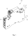
- the residual current operated circuit breaker 100 comprises a housing 10.
- the housing 10 comprises a first housing 11, a second housing 12 and an installation housing 13.
- the installation housing 13 is located between the first housing 11 and the second housing 12.
- a first accommodating chamber is formed between the first housing 11 and the installation housing 13;
- a second accommodating chamber is formed between the second housing 12 and the installation housing 13.
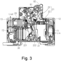
- the residual current operated circuit breaker 100 has a first current loop and a second current loop, wherein the first current loop is located in the first accommodating chamber, and the second current loop is located in the second accommodating chamber.
- the residual current operated circuit breaker 100 further comprises an electromagnetic trip apparatus 20, an arc extinguishing apparatus 30, a first operating mechanism 21, a leakage trip apparatus 40 and a second operating mechanism 42.
- the electromagnetic trip apparatus 20 and the arc extinguishing apparatus 30 are disposed in the first accommodating chamber.
- the first operating mechanism 21 is used for working in cooperation with the electromagnetic trip apparatus 20 and is located on one side of the first accommodating chamber; the action of the first operating mechanism 21 can realize opening and closing of the first current loop, for the purpose of realizing overcurrent protection of the residual current operated circuit breaker 100; the arc extinguishing apparatus 30 facilitates rapid extinguishing of an arc.
- the leakage trip apparatus 40 is disposed in the second accommodating chamber; the second operating mechanism 42 is used for working in cooperation with the leakage trip apparatus 40 and is located on one side of the second accommodating chamber; the action of the second operating mechanism 42 can realize opening and closing of the second current loop, for the purpose of realizing leakage protection of the residual current operated circuit breaker 100.
- the residual current operated circuit breaker 100 of the present invention also comprises a thermal protection assembly 31 formed of a bimetallic strip, which is close to the arc extinguishing apparatus 30 and located in the first accommodating chamber, and a circuit board assembly 80 for detection and control signal output, disposed in the second accommodating chamber.
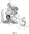
- the residual current operated circuit breaker of the present invention also comprises a first terminal assembly 71 which may be used for an L pole incoming line, a second terminal assembly 72 which may be used for an L pole outgoing line, and a third terminal assembly 51 which may be used for an N pole incoming line.
- the first terminal assembly 71 of the present invention is of large size; in order to satisfy reliability of installation of the first terminal assembly 71 without increasing the size of the housing, preferably, an installation gap is provided on one side of the installation housing 13, and the first terminal assembly 71 can run through the installation gap and be clamped in the space formed by the first housing 11 and the second housing 12.
- the second terminal assembly 72 is accommodated in the first accommodating chamber, and the third terminal assembly 51 is accommodated in the second accommodating chamber.
- the second terminal assembly 72 is located on one side, close to the electromagnetic trip apparatus, in the first accommodating chamber.
- a wiring capacity of the first terminal assembly 71 is larger than a wiring capacity of the third terminal assembly 51. Since the first terminal assembly 71 of the present invention replaces a small terminal assembly used in the prior art, the use of a large terminal assembly with a larger wiring capacity can effectively enhance the electrical safety and reliability of L pole wiring. According to a preferred embodiment of the present invention, the first terminal assembly 71 has a current carrying range of 6 A - 32 A.
- the first terminal assembly 71 is optionally connected to a common bus bar; an L pole incoming line end may be connected to a conductor of larger cross section, to meet the needs of large current input at the L pole, enhancing product applicability, and increasing product competitiveness more effectively.
- a slider 83 is also disposed on one side of the housing 10 of the present invention, close to the first terminal assembly 71; the slider 83 can avoid the need for a user's finger to come into contact with electrified components, in order to effectively protect the user's personal safety, and also facilitates the task of removably connecting the circuit breaker to a corresponding rail in a flexible manner.
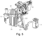
- the residual current operated circuit breaker of the present invention differs from the prior art in that an N pole outgoing line is realized by means of a flexible conductor assembly 60, and the flexible conductor assembly 60 has a contact opening/closing function, thereby being able to enhance the electrical safety and reliability of an N pole current loop.
- the flexible conductor assembly 60 is accommodated in the second accommodating chamber.
- an incoming line end of the third terminal assembly 51 and an outgoing line end of the flexible conductor assembly 60 are located on the same side of the housing 10; this design facilitates product installation and wiring, and increases user space utilization rate.
- the first operating mechanism 21 comprises: a first contact assembly 22 and a first actuating assembly 23.
- the second operating mechanism 42 comprises a second contact assembly 43 and a second actuating assembly 44. More specifically, the action of the first contact assembly 22 and the first actuating assembly 23 can realize the opening and closing of an L pole current loop. The action of the second contact assembly 43 and the second actuating assembly 44 can realize the opening and closing of the N pole current loop. Linked movement of the first actuating assembly 23 and second actuating assembly 44 may be realized by means of a drive element 81 and an operating handle 82.
- the flexible conductor assembly 60 comprises a connecting plate 63, a first connecting conductor 61 and a second connecting conductor 62.
- first connecting conductor 61 is connected to a static contact 431 in the second contact assembly 43; another end of the first connecting conductor 61 is connected to the connecting plate 63.
- One end of the second connecting conductor 62 is connected to the connecting plate 63; another end of the second connecting conductor 62 is a free connection end and extends to the outside of the housing 10.
- the direction of the L pole current loop of the present invention is, in sequence, the first terminal assembly 71, an L pole moving contact 222, an L pole static contact 221 and the second terminal assembly 72.
- the direction of the N pole current loop is, in sequence, the third terminal assembly 51, an N pole moving contact 432, the N pole static contact 431, the first connecting conductor 61, the connecting plate 63 and the second connecting conductor 62.
- the connecting plate 63 may have a bent structure, and can be stably engaged in an installation groove formed jointly by multiple limiting ribs on an inner surface of the housing.
- the connecting plate 63 is also provided with a first bent part 631 and a second bent part 632.
- the first bent part 631 may be trough-shaped, and an end of the first connecting conductor 61 can be accommodated in the trough-shaped first bent part 631.
- the second bent part 632 may be plate-like, and an end of the second connecting conductor 62 is crimped to the plate-like second bent part 632. It is worth pointing out that the shape and structure of the connecting plate 63 are not unique; those skilled in the art could make various changes and substitutions according to actual needs when the same functions can be realized, without departing from the scope of protection of the present invention.
- the residual current operated circuit breaker according to the present invention can provide the user with a method of wiring that is more convenient and reliable, and on condition that it is ensured that the product has perfect safety protection, still has an optimal housing structure, effectively saving installation space for the user, and at the same time, since a flexible conductor is used to replace a wiring terminal, the processing technology of the product can be simplified, and the product cost is reduced.
Landscapes
- Engineering & Computer Science (AREA)
- Power Engineering (AREA)
- Breakers (AREA)
Claims (7)
- Fehlerstromschutzschalter (100), umfassend:ein Gehäuse (10), das ein erstes Gehäuse (11), ein zweites Gehäuse (12) und ein dazwischen angeordnetes Installationsgehäuse (13) umfasst, wobei zwischen dem ersten Gehäuse (11) und dem Installationsgehäuse (13) eine erste Aufnahmekammer und zwischen dem zweiten Gehäuse (12) und dem Installationsgehäuse (13) eine zweite Aufnahmekammer gebildet wird;eine elektromagnetische Auslösevorrichtung (20) und eine Lichtbogenlöschvorrichtung (30), die in der ersten Aufnahmekammer angeordnet sind;einen ersten Betätigungsmechanismus (21), der zum Zusammenwirken mit der elektromagnetischen Auslösevorrichtung (20) verwendet wird und auf einer Seite der ersten Aufnahmekammer angeordnet ist und eine erste Kontaktanordnung (22) und eine erste Betätigungsanordnung (23) umfasst;ein Erdschluss-Schutzschalter (40), der in der zweiten Aufnahmekammer angeordnet ist;einen zweiten Betätigungsmechanismus (42), der zum Zusammenwirken mit dem Erdschluss-Schutzschalter (40) verwendet wird und sich auf einer Seite der zweiten Aufnahmekammer befindet und eine zweite Kontaktanordnung (43) und eine zweite Betätigungsanordnung (44) umfasst, wobei Aktionen des ersten Betätigungsmechanismus (21) und des zweiten Betätigungsmechanismus (42) in der Lage sind, das Öffnen und Schließen einer Stromschleife zu realisieren, und wobei eine gekoppelte Bewegung der ersten Betätigungsanordnung (23) und der zweiten Betätigungsanordnung (44) mittels eines Antriebselements (81) und eines Betätigungsgriffs (82) realisiert wird;eine erste Anschlussanordnung (71), die für eine ankommende L-Pol-Leitung verwendet werden kann, wobei auf einer Seite des Installationsgehäuses (13) ein Installationszwischenraum vorgesehen ist, wobei die erste Anschlussanordnung (71) durch den Installationsspalt laufen kann und in einem durch das erste Gehäuse (11) und das zweite Gehäuse (12) gebildeten Raum eingeklemmt ist;eine zweite Anschlussanordnung (72), die für eine abgehende L-Pol-Leitung verwendet werden kann, in der ersten Aufnahmekammer untergebracht ist;eine dritte Anschlussanordnung (51), die für eine ankommende N-Pol-Leitung verwendet werden kann und in der zweiten Aufnahmekammer untergebracht ist,dadurch gekennzeichnet, dass er ferner umfasst:
eine flexible Leiteranordnung (60) mit einer Kontaktöffnungs-/-schließfunktion, die für eine abgehende N-Pol-Leitung verwendet werden kann, die in der zweiten Aufnahmekammer untergebracht ist, wobei die flexible Leiteranordnung (60) umfasst:eine Verbindungsplatte (63);einen ersten Verbindungsleiter (61), dessen eines Ende mit einem statischen Kontakt (431) in der zweiten Kontaktanordnung (43) und dessen anderes Ende mit der Verbindungsplatte (63) verbunden ist;einen zweiten Verbindungsleiter (62), dessen eines Ende mit der Verbindungsplatte (63) verbunden ist und dessen anderes Ende ein freies Anschlussende ist und sich zur Außenseite des Gehäuses (10) erstreckt, wobei die Verbindungsplatte (63) eine gebogene Struktur ist und mit einem wannenförmigen ersten gebogenen Teil (631) versehen ist, wobei ein Ende des ersten Verbindungsleiters (61) in dem ersten gebogenen Teil (631) untergebracht ist, und mit einem plattenförmigen zweiten gebogenen Teil (632), wobei ein Ende des zweiten Verbindungsleiters (62) an den zweiten gebogenen Teil (632) gecrimpt ist. - Fehlerstromschutzschalter gemäß Anspruch 1, wobei die zweite Anschlussanordnung (72) auf einer Seite in der Nähe der elektromagnetischen Auslösevorrichtung (20) in der ersten Aufnahmekammer angeordnet ist.
- Fehlerstromschutzschalter gemäß Anspruch 1, wobei ein ankommendes Leitungsende der dritten Anschlussanordnung (51) und ein abgehendes Leitungsende der flexiblen Leiteranordnung (60) auf der gleichen Seite des Gehäuses (10) angeordnet sind.
- Fehlerstromschutzschalter gemäß Anspruch 1, wobei die Verdrahtungskapazität der ersten Anschlussanordnung (71) größer als die Verdrahtungskapazität der dritten Anschlussanordnung (51) ist.
- Fehlerstromschutzschalter gemäß Anspruch 1, wobei die erste Anschlussanordnung (71) einen Stromführungsbereich von 6 A - 32 A aufweist und die erste Anschlussanordnung (71) mit einer gemeinsamen Sammelschiene verbunden werden kann.
- Fehlerstromschutzschalter gemäß Anspruch 1, wobei die Richtung einer N-Pol-Stromschleife des Fehlerstromschutzschalters (100) in der Reihenfolge dritte Anschlussanordnung (51), beweglicher N-Pol-Kontakt (432), statischer N-Pol-Kontakt (431), erster Verbindungsleiter (61), Verbindungsplatte (63) und zweiter Verbindungsleiter (62) ausgelegt ist.
- Fehlerstromschutzschalter gemäß Anspruch 1, ferner umfassend eine Wärmeschutzanordnung (31), die sich in der Nähe der Lichtbogenlöschvorrichtung (30) befindet und in der ersten Aufnahmekammer angeordnet ist.
Applications Claiming Priority (1)
| Application Number | Priority Date | Filing Date | Title |
|---|---|---|---|
| CN201710221946.4A CN108695115B (zh) | 2017-04-06 | 2017-04-06 | 剩余电流动作断路器 |
Publications (2)
| Publication Number | Publication Date |
|---|---|
| EP3385974A1 EP3385974A1 (de) | 2018-10-10 |
| EP3385974B1 true EP3385974B1 (de) | 2024-02-14 |
Family
ID=61906749
Family Applications (1)
| Application Number | Title | Priority Date | Filing Date |
|---|---|---|---|
| EP18165872.5A Active EP3385974B1 (de) | 2017-04-06 | 2018-04-05 | Fehlerstromschutzschalter |
Country Status (2)
| Country | Link |
|---|---|
| EP (1) | EP3385974B1 (de) |
| CN (1) | CN108695115B (de) |
Families Citing this family (3)
| Publication number | Priority date | Publication date | Assignee | Title |
|---|---|---|---|---|
| CN111223727A (zh) * | 2018-11-27 | 2020-06-02 | 俊郎电气有限公司 | 一种c65小型漏电接地故障保护断路器 |
| CN109817495A (zh) * | 2019-01-22 | 2019-05-28 | 天津京人电器有限公司 | 一种具有l极和n极组合的二极小型断路器 |
| DE202019001746U1 (de) * | 2019-04-17 | 2019-05-20 | Siemens Aktiengesellschaft | Kompakt-Schutzschaltgerät |
Family Cites Families (7)
| Publication number | Priority date | Publication date | Assignee | Title |
|---|---|---|---|---|
| CN101728126A (zh) * | 2008-10-13 | 2010-06-09 | 施耐德电器工业公司 | 电子式漏电保护器 |
| US7994882B2 (en) * | 2009-04-18 | 2011-08-09 | General Electric Company | Space allocation within a circuit breaker |
| CN201725756U (zh) * | 2010-06-30 | 2011-01-26 | 宏达电器集团有限公司 | 剩余电流断路器 |
| US20120250206A1 (en) * | 2011-03-30 | 2012-10-04 | General Electric Company | Compact residual current breaker with overcurrent protection |
| CN102760622B (zh) * | 2012-07-23 | 2016-03-16 | 乐清市智顺电气有限公司 | 无加长宽度为18mm多功能漏电断路器 |
| CN203690222U (zh) * | 2013-09-18 | 2014-07-02 | 德力西电气有限公司 | 一种可上下接线的电子式漏电断路器 |
| CN106158546B (zh) * | 2015-03-26 | 2019-08-13 | 西门子公司 | 断路器 |
-
2017
- 2017-04-06 CN CN201710221946.4A patent/CN108695115B/zh active Active
-
2018
- 2018-04-05 EP EP18165872.5A patent/EP3385974B1/de active Active
Also Published As
| Publication number | Publication date |
|---|---|
| EP3385974A1 (de) | 2018-10-10 |
| CN108695115A (zh) | 2018-10-23 |
| CN108695115B (zh) | 2020-05-26 |
Similar Documents
| Publication | Publication Date | Title |
|---|---|---|
| EP0399282B1 (de) | Automatischer magneto-thermischer Schutzschalter mit hoher Ausschaltleistung | |
| EP3385974B1 (de) | Fehlerstromschutzschalter | |
| US7268651B2 (en) | Electromechanical switching device | |
| SE0102424L (sv) | Säkringsförsedd frånskiljare | |
| WO2001050488A2 (en) | Arc chamber for low-voltage circuit breakers | |
| US9012801B2 (en) | Flexible shunt for vacuum circuit breaker | |
| US9524842B2 (en) | Molded case circuit breakers with a switch PCB over an internal pocket and behind a front cover | |
| JP2020024961A (ja) | 開閉器及び分電盤 | |
| CN204407264U (zh) | 一种断路器壳本体结构 | |
| EP3541153A2 (de) | Flexible leiterplatte und schutzschalter mit einer flexiblen leiterplatte | |
| CN204407262U (zh) | 一种断路器壳本体结构 | |
| AU2022204661B2 (en) | Miniature circuit breaker | |
| JP2002110022A (ja) | 住宅用分電盤の主幹開閉器 | |
| US3293392A (en) | Fuse protected electrical switch | |
| JP7019095B2 (ja) | 接続変換アダプタおよび電気機器 | |
| TW345671B (en) | Circuit breaker | |
| KR101651749B1 (ko) | 회로 차단기 | |
| KR101800730B1 (ko) | 일체형 다중 스위치 | |
| KR970051615A (ko) | 회로차단기 | |
| EP1178509A3 (de) | Thermomagnetischer Schutzschalter | |
| CN105810511A (zh) | 一种断路器壳本体结构 | |
| CN209571363U (zh) | 安全型热保护器 | |
| CN1963976B (zh) | 电路断路器 | |
| CN223785021U (zh) | 开关器件及电力系统 | |
| CN216435773U (zh) | 具有增磁组件的触头系统、断路器和隔离开关 |
Legal Events
| Date | Code | Title | Description |
|---|---|---|---|
| PUAI | Public reference made under article 153(3) epc to a published international application that has entered the european phase |
Free format text: ORIGINAL CODE: 0009012 |
|
| STAA | Information on the status of an ep patent application or granted ep patent |
Free format text: STATUS: THE APPLICATION HAS BEEN PUBLISHED |
|
| AK | Designated contracting states |
Kind code of ref document: A1 Designated state(s): AL AT BE BG CH CY CZ DE DK EE ES FI FR GB GR HR HU IE IS IT LI LT LU LV MC MK MT NL NO PL PT RO RS SE SI SK SM TR |
|
| AX | Request for extension of the european patent |
Extension state: BA ME |
|
| STAA | Information on the status of an ep patent application or granted ep patent |
Free format text: STATUS: REQUEST FOR EXAMINATION WAS MADE |
|
| 17P | Request for examination filed |
Effective date: 20190328 |
|
| RBV | Designated contracting states (corrected) |
Designated state(s): AL AT BE BG CH CY CZ DE DK EE ES FI FR GB GR HR HU IE IS IT LI LT LU LV MC MK MT NL NO PL PT RO RS SE SI SK SM TR |
|
| STAA | Information on the status of an ep patent application or granted ep patent |
Free format text: STATUS: EXAMINATION IS IN PROGRESS |
|
| 17Q | First examination report despatched |
Effective date: 20210520 |
|
| RIC1 | Information provided on ipc code assigned before grant |
Ipc: H01H 71/02 20060101ALN20230731BHEP Ipc: H01H 71/40 20060101ALN20230731BHEP Ipc: H01H 71/08 20060101ALN20230731BHEP Ipc: H01H 83/22 20060101AFI20230731BHEP |
|
| RIC1 | Information provided on ipc code assigned before grant |
Ipc: H01H 71/02 20060101ALN20230817BHEP Ipc: H01H 71/40 20060101ALN20230817BHEP Ipc: H01H 71/08 20060101ALN20230817BHEP Ipc: H01H 83/22 20060101AFI20230817BHEP |
|
| GRAP | Despatch of communication of intention to grant a patent |
Free format text: ORIGINAL CODE: EPIDOSNIGR1 |
|
| STAA | Information on the status of an ep patent application or granted ep patent |
Free format text: STATUS: GRANT OF PATENT IS INTENDED |
|
| INTG | Intention to grant announced |
Effective date: 20230928 |
|
| GRAS | Grant fee paid |
Free format text: ORIGINAL CODE: EPIDOSNIGR3 |
|
| GRAA | (expected) grant |
Free format text: ORIGINAL CODE: 0009210 |
|
| STAA | Information on the status of an ep patent application or granted ep patent |
Free format text: STATUS: THE PATENT HAS BEEN GRANTED |
|
| AK | Designated contracting states |
Kind code of ref document: B1 Designated state(s): AL AT BE BG CH CY CZ DE DK EE ES FI FR GB GR HR HU IE IS IT LI LT LU LV MC MK MT NL NO PL PT RO RS SE SI SK SM TR |
|
| REG | Reference to a national code |
Ref country code: GB Ref legal event code: FG4D |
|
| REG | Reference to a national code |
Ref country code: CH Ref legal event code: EP |
|
| REG | Reference to a national code |
Ref country code: DE Ref legal event code: R096 Ref document number: 602018065129 Country of ref document: DE |
|
| REG | Reference to a national code |
Ref country code: IE Ref legal event code: FG4D |
|
| REG | Reference to a national code |
Ref country code: LT Ref legal event code: MG9D |
|
| REG | Reference to a national code |
Ref country code: NL Ref legal event code: MP Effective date: 20240214 |
|
| PG25 | Lapsed in a contracting state [announced via postgrant information from national office to epo] |
Ref country code: IS Free format text: LAPSE BECAUSE OF FAILURE TO SUBMIT A TRANSLATION OF THE DESCRIPTION OR TO PAY THE FEE WITHIN THE PRESCRIBED TIME-LIMIT Effective date: 20240614 |
|
| PG25 | Lapsed in a contracting state [announced via postgrant information from national office to epo] |
Ref country code: LT Free format text: LAPSE BECAUSE OF FAILURE TO SUBMIT A TRANSLATION OF THE DESCRIPTION OR TO PAY THE FEE WITHIN THE PRESCRIBED TIME-LIMIT Effective date: 20240214 |
|
| PG25 | Lapsed in a contracting state [announced via postgrant information from national office to epo] |
Ref country code: GR Free format text: LAPSE BECAUSE OF FAILURE TO SUBMIT A TRANSLATION OF THE DESCRIPTION OR TO PAY THE FEE WITHIN THE PRESCRIBED TIME-LIMIT Effective date: 20240515 |
|
| REG | Reference to a national code |
Ref country code: AT Ref legal event code: MK05 Ref document number: 1657787 Country of ref document: AT Kind code of ref document: T Effective date: 20240214 |
|
| PG25 | Lapsed in a contracting state [announced via postgrant information from national office to epo] |
Ref country code: RS Free format text: LAPSE BECAUSE OF FAILURE TO SUBMIT A TRANSLATION OF THE DESCRIPTION OR TO PAY THE FEE WITHIN THE PRESCRIBED TIME-LIMIT Effective date: 20240514 Ref country code: HR Free format text: LAPSE BECAUSE OF FAILURE TO SUBMIT A TRANSLATION OF THE DESCRIPTION OR TO PAY THE FEE WITHIN THE PRESCRIBED TIME-LIMIT Effective date: 20240214 Ref country code: NL Free format text: LAPSE BECAUSE OF FAILURE TO SUBMIT A TRANSLATION OF THE DESCRIPTION OR TO PAY THE FEE WITHIN THE PRESCRIBED TIME-LIMIT Effective date: 20240214 |
|
| PG25 | Lapsed in a contracting state [announced via postgrant information from national office to epo] |
Ref country code: ES Free format text: LAPSE BECAUSE OF FAILURE TO SUBMIT A TRANSLATION OF THE DESCRIPTION OR TO PAY THE FEE WITHIN THE PRESCRIBED TIME-LIMIT Effective date: 20240214 |
|
| PG25 | Lapsed in a contracting state [announced via postgrant information from national office to epo] |
Ref country code: AT Free format text: LAPSE BECAUSE OF FAILURE TO SUBMIT A TRANSLATION OF THE DESCRIPTION OR TO PAY THE FEE WITHIN THE PRESCRIBED TIME-LIMIT Effective date: 20240214 |
|
| PG25 | Lapsed in a contracting state [announced via postgrant information from national office to epo] |
Ref country code: RS Free format text: LAPSE BECAUSE OF FAILURE TO SUBMIT A TRANSLATION OF THE DESCRIPTION OR TO PAY THE FEE WITHIN THE PRESCRIBED TIME-LIMIT Effective date: 20240514 Ref country code: NO Free format text: LAPSE BECAUSE OF FAILURE TO SUBMIT A TRANSLATION OF THE DESCRIPTION OR TO PAY THE FEE WITHIN THE PRESCRIBED TIME-LIMIT Effective date: 20240514 Ref country code: NL Free format text: LAPSE BECAUSE OF FAILURE TO SUBMIT A TRANSLATION OF THE DESCRIPTION OR TO PAY THE FEE WITHIN THE PRESCRIBED TIME-LIMIT Effective date: 20240214 Ref country code: LT Free format text: LAPSE BECAUSE OF FAILURE TO SUBMIT A TRANSLATION OF THE DESCRIPTION OR TO PAY THE FEE WITHIN THE PRESCRIBED TIME-LIMIT Effective date: 20240214 Ref country code: IS Free format text: LAPSE BECAUSE OF FAILURE TO SUBMIT A TRANSLATION OF THE DESCRIPTION OR TO PAY THE FEE WITHIN THE PRESCRIBED TIME-LIMIT Effective date: 20240614 Ref country code: HR Free format text: LAPSE BECAUSE OF FAILURE TO SUBMIT A TRANSLATION OF THE DESCRIPTION OR TO PAY THE FEE WITHIN THE PRESCRIBED TIME-LIMIT Effective date: 20240214 Ref country code: GR Free format text: LAPSE BECAUSE OF FAILURE TO SUBMIT A TRANSLATION OF THE DESCRIPTION OR TO PAY THE FEE WITHIN THE PRESCRIBED TIME-LIMIT Effective date: 20240515 Ref country code: FI Free format text: LAPSE BECAUSE OF FAILURE TO SUBMIT A TRANSLATION OF THE DESCRIPTION OR TO PAY THE FEE WITHIN THE PRESCRIBED TIME-LIMIT Effective date: 20240214 Ref country code: ES Free format text: LAPSE BECAUSE OF FAILURE TO SUBMIT A TRANSLATION OF THE DESCRIPTION OR TO PAY THE FEE WITHIN THE PRESCRIBED TIME-LIMIT Effective date: 20240214 Ref country code: BG Free format text: LAPSE BECAUSE OF FAILURE TO SUBMIT A TRANSLATION OF THE DESCRIPTION OR TO PAY THE FEE WITHIN THE PRESCRIBED TIME-LIMIT Effective date: 20240214 Ref country code: AT Free format text: LAPSE BECAUSE OF FAILURE TO SUBMIT A TRANSLATION OF THE DESCRIPTION OR TO PAY THE FEE WITHIN THE PRESCRIBED TIME-LIMIT Effective date: 20240214 |
|
| PG25 | Lapsed in a contracting state [announced via postgrant information from national office to epo] |
Ref country code: PL Free format text: LAPSE BECAUSE OF FAILURE TO SUBMIT A TRANSLATION OF THE DESCRIPTION OR TO PAY THE FEE WITHIN THE PRESCRIBED TIME-LIMIT Effective date: 20240214 Ref country code: PT Free format text: LAPSE BECAUSE OF FAILURE TO SUBMIT A TRANSLATION OF THE DESCRIPTION OR TO PAY THE FEE WITHIN THE PRESCRIBED TIME-LIMIT Effective date: 20240614 |
|
| PG25 | Lapsed in a contracting state [announced via postgrant information from national office to epo] |
Ref country code: SE Free format text: LAPSE BECAUSE OF FAILURE TO SUBMIT A TRANSLATION OF THE DESCRIPTION OR TO PAY THE FEE WITHIN THE PRESCRIBED TIME-LIMIT Effective date: 20240214 Ref country code: PT Free format text: LAPSE BECAUSE OF FAILURE TO SUBMIT A TRANSLATION OF THE DESCRIPTION OR TO PAY THE FEE WITHIN THE PRESCRIBED TIME-LIMIT Effective date: 20240614 Ref country code: PL Free format text: LAPSE BECAUSE OF FAILURE TO SUBMIT A TRANSLATION OF THE DESCRIPTION OR TO PAY THE FEE WITHIN THE PRESCRIBED TIME-LIMIT Effective date: 20240214 Ref country code: LV Free format text: LAPSE BECAUSE OF FAILURE TO SUBMIT A TRANSLATION OF THE DESCRIPTION OR TO PAY THE FEE WITHIN THE PRESCRIBED TIME-LIMIT Effective date: 20240214 |
|
| PG25 | Lapsed in a contracting state [announced via postgrant information from national office to epo] |
Ref country code: DK Free format text: LAPSE BECAUSE OF FAILURE TO SUBMIT A TRANSLATION OF THE DESCRIPTION OR TO PAY THE FEE WITHIN THE PRESCRIBED TIME-LIMIT Effective date: 20240214 |
|
| PG25 | Lapsed in a contracting state [announced via postgrant information from national office to epo] |
Ref country code: SM Free format text: LAPSE BECAUSE OF FAILURE TO SUBMIT A TRANSLATION OF THE DESCRIPTION OR TO PAY THE FEE WITHIN THE PRESCRIBED TIME-LIMIT Effective date: 20240214 |
|
| PG25 | Lapsed in a contracting state [announced via postgrant information from national office to epo] |
Ref country code: CZ Free format text: LAPSE BECAUSE OF FAILURE TO SUBMIT A TRANSLATION OF THE DESCRIPTION OR TO PAY THE FEE WITHIN THE PRESCRIBED TIME-LIMIT Effective date: 20240214 Ref country code: EE Free format text: LAPSE BECAUSE OF FAILURE TO SUBMIT A TRANSLATION OF THE DESCRIPTION OR TO PAY THE FEE WITHIN THE PRESCRIBED TIME-LIMIT Effective date: 20240214 |
|
| PG25 | Lapsed in a contracting state [announced via postgrant information from national office to epo] |
Ref country code: SK Free format text: LAPSE BECAUSE OF FAILURE TO SUBMIT A TRANSLATION OF THE DESCRIPTION OR TO PAY THE FEE WITHIN THE PRESCRIBED TIME-LIMIT Effective date: 20240214 |
|
| PG25 | Lapsed in a contracting state [announced via postgrant information from national office to epo] |
Ref country code: SM Free format text: LAPSE BECAUSE OF FAILURE TO SUBMIT A TRANSLATION OF THE DESCRIPTION OR TO PAY THE FEE WITHIN THE PRESCRIBED TIME-LIMIT Effective date: 20240214 Ref country code: SK Free format text: LAPSE BECAUSE OF FAILURE TO SUBMIT A TRANSLATION OF THE DESCRIPTION OR TO PAY THE FEE WITHIN THE PRESCRIBED TIME-LIMIT Effective date: 20240214 Ref country code: RO Free format text: LAPSE BECAUSE OF FAILURE TO SUBMIT A TRANSLATION OF THE DESCRIPTION OR TO PAY THE FEE WITHIN THE PRESCRIBED TIME-LIMIT Effective date: 20240214 Ref country code: EE Free format text: LAPSE BECAUSE OF FAILURE TO SUBMIT A TRANSLATION OF THE DESCRIPTION OR TO PAY THE FEE WITHIN THE PRESCRIBED TIME-LIMIT Effective date: 20240214 Ref country code: DK Free format text: LAPSE BECAUSE OF FAILURE TO SUBMIT A TRANSLATION OF THE DESCRIPTION OR TO PAY THE FEE WITHIN THE PRESCRIBED TIME-LIMIT Effective date: 20240214 Ref country code: CZ Free format text: LAPSE BECAUSE OF FAILURE TO SUBMIT A TRANSLATION OF THE DESCRIPTION OR TO PAY THE FEE WITHIN THE PRESCRIBED TIME-LIMIT Effective date: 20240214 |
|
| REG | Reference to a national code |
Ref country code: DE Ref legal event code: R097 Ref document number: 602018065129 Country of ref document: DE |
|
| PG25 | Lapsed in a contracting state [announced via postgrant information from national office to epo] |
Ref country code: MC Free format text: LAPSE BECAUSE OF FAILURE TO SUBMIT A TRANSLATION OF THE DESCRIPTION OR TO PAY THE FEE WITHIN THE PRESCRIBED TIME-LIMIT Effective date: 20240214 |
|
| PG25 | Lapsed in a contracting state [announced via postgrant information from national office to epo] |
Ref country code: MC Free format text: LAPSE BECAUSE OF FAILURE TO SUBMIT A TRANSLATION OF THE DESCRIPTION OR TO PAY THE FEE WITHIN THE PRESCRIBED TIME-LIMIT Effective date: 20240214 |
|
| REG | Reference to a national code |
Ref country code: CH Ref legal event code: PL |
|
| PG25 | Lapsed in a contracting state [announced via postgrant information from national office to epo] |
Ref country code: IT Free format text: LAPSE BECAUSE OF FAILURE TO SUBMIT A TRANSLATION OF THE DESCRIPTION OR TO PAY THE FEE WITHIN THE PRESCRIBED TIME-LIMIT Effective date: 20240214 |
|
| PG25 | Lapsed in a contracting state [announced via postgrant information from national office to epo] |
Ref country code: LU Free format text: LAPSE BECAUSE OF NON-PAYMENT OF DUE FEES Effective date: 20240405 |
|
| PLBE | No opposition filed within time limit |
Free format text: ORIGINAL CODE: 0009261 |
|
| STAA | Information on the status of an ep patent application or granted ep patent |
Free format text: STATUS: NO OPPOSITION FILED WITHIN TIME LIMIT |
|
| REG | Reference to a national code |
Ref country code: BE Ref legal event code: MM Effective date: 20240430 |
|
| PG25 | Lapsed in a contracting state [announced via postgrant information from national office to epo] |
Ref country code: LU Free format text: LAPSE BECAUSE OF NON-PAYMENT OF DUE FEES Effective date: 20240405 Ref country code: IT Free format text: LAPSE BECAUSE OF FAILURE TO SUBMIT A TRANSLATION OF THE DESCRIPTION OR TO PAY THE FEE WITHIN THE PRESCRIBED TIME-LIMIT Effective date: 20240214 |
|
| PG25 | Lapsed in a contracting state [announced via postgrant information from national office to epo] |
Ref country code: BE Free format text: LAPSE BECAUSE OF NON-PAYMENT OF DUE FEES Effective date: 20240430 |
|
| PG25 | Lapsed in a contracting state [announced via postgrant information from national office to epo] |
Ref country code: FR Free format text: LAPSE BECAUSE OF NON-PAYMENT OF DUE FEES Effective date: 20240414 |
|
| 26N | No opposition filed |
Effective date: 20241115 |
|
| GBPC | Gb: european patent ceased through non-payment of renewal fee |
Effective date: 20240514 |
|
| PG25 | Lapsed in a contracting state [announced via postgrant information from national office to epo] |
Ref country code: FR Free format text: LAPSE BECAUSE OF NON-PAYMENT OF DUE FEES Effective date: 20240414 Ref country code: BE Free format text: LAPSE BECAUSE OF NON-PAYMENT OF DUE FEES Effective date: 20240430 Ref country code: CH Free format text: LAPSE BECAUSE OF NON-PAYMENT OF DUE FEES Effective date: 20240430 |
|
| PG25 | Lapsed in a contracting state [announced via postgrant information from national office to epo] |
Ref country code: IE Free format text: LAPSE BECAUSE OF NON-PAYMENT OF DUE FEES Effective date: 20240405 |
|
| PG25 | Lapsed in a contracting state [announced via postgrant information from national office to epo] |
Ref country code: SI Free format text: LAPSE BECAUSE OF FAILURE TO SUBMIT A TRANSLATION OF THE DESCRIPTION OR TO PAY THE FEE WITHIN THE PRESCRIBED TIME-LIMIT Effective date: 20240214 |
|
| PG25 | Lapsed in a contracting state [announced via postgrant information from national office to epo] |
Ref country code: GB Free format text: LAPSE BECAUSE OF NON-PAYMENT OF DUE FEES Effective date: 20240514 |
|
| PGFP | Annual fee paid to national office [announced via postgrant information from national office to epo] |
Ref country code: DE Payment date: 20250620 Year of fee payment: 8 |
|
| PG25 | Lapsed in a contracting state [announced via postgrant information from national office to epo] |
Ref country code: CY Free format text: LAPSE BECAUSE OF FAILURE TO SUBMIT A TRANSLATION OF THE DESCRIPTION OR TO PAY THE FEE WITHIN THE PRESCRIBED TIME-LIMIT; INVALID AB INITIO Effective date: 20180405 |
|
| PG25 | Lapsed in a contracting state [announced via postgrant information from national office to epo] |
Ref country code: HU Free format text: LAPSE BECAUSE OF FAILURE TO SUBMIT A TRANSLATION OF THE DESCRIPTION OR TO PAY THE FEE WITHIN THE PRESCRIBED TIME-LIMIT; INVALID AB INITIO Effective date: 20180405 |
|
| PG25 | Lapsed in a contracting state [announced via postgrant information from national office to epo] |
Ref country code: TR Free format text: LAPSE BECAUSE OF FAILURE TO SUBMIT A TRANSLATION OF THE DESCRIPTION OR TO PAY THE FEE WITHIN THE PRESCRIBED TIME-LIMIT Effective date: 20240214 |