EP3386077A1 - Boîtier de connexion de moteur et moteur de convertisseur - Google Patents
Boîtier de connexion de moteur et moteur de convertisseur Download PDFInfo
- Publication number
- EP3386077A1 EP3386077A1 EP18000333.7A EP18000333A EP3386077A1 EP 3386077 A1 EP3386077 A1 EP 3386077A1 EP 18000333 A EP18000333 A EP 18000333A EP 3386077 A1 EP3386077 A1 EP 3386077A1
- Authority
- EP
- European Patent Office
- Prior art keywords
- motor
- connection box
- motor connection
- circuit board
- box according
- Prior art date
- Legal status (The legal status is an assumption and is not a legal conclusion. Google has not performed a legal analysis and makes no representation as to the accuracy of the status listed.)
- Granted
Links
Images


Classifications
-
- H—ELECTRICITY
- H02—GENERATION; CONVERSION OR DISTRIBUTION OF ELECTRIC POWER
- H02K—DYNAMO-ELECTRIC MACHINES
- H02K5/00—Casings; Enclosures; Supports
- H02K5/04—Casings or enclosures characterised by the shape, form or construction thereof
- H02K5/22—Auxiliary parts of casings not covered by groups H02K5/06-H02K5/20, e.g. shaped to form connection boxes or terminal boxes
- H02K5/225—Terminal boxes or connection arrangements
-
- H—ELECTRICITY
- H02—GENERATION; CONVERSION OR DISTRIBUTION OF ELECTRIC POWER
- H02K—DYNAMO-ELECTRIC MACHINES
- H02K11/00—Structural association of dynamo-electric machines with electric components or with devices for shielding, monitoring or protection
- H02K11/30—Structural association with control circuits or drive circuits
- H02K11/33—Drive circuits, e.g. power electronics
-
- H—ELECTRICITY
- H02—GENERATION; CONVERSION OR DISTRIBUTION OF ELECTRIC POWER
- H02K—DYNAMO-ELECTRIC MACHINES
- H02K5/00—Casings; Enclosures; Supports
- H02K5/04—Casings or enclosures characterised by the shape, form or construction thereof
- H02K5/20—Casings or enclosures characterised by the shape, form or construction thereof with channels or ducts for flow of cooling medium
- H02K5/207—Casings or enclosures characterised by the shape, form or construction thereof with channels or ducts for flow of cooling medium with openings in the casing specially adapted for ambient air
-
- H—ELECTRICITY
- H02—GENERATION; CONVERSION OR DISTRIBUTION OF ELECTRIC POWER
- H02K—DYNAMO-ELECTRIC MACHINES
- H02K9/00—Arrangements for cooling or ventilating
- H02K9/14—Arrangements for cooling or ventilating wherein gaseous cooling medium circulates between the machine casing and a surrounding mantle
Definitions
- the invention relates to a motor connection box and an inverter motor.
- inverter motor is understood in this document an electrically operated drive unit comprising at least one motor unit and an electronic assembly, the inverter unit for controlling the motor unit, in particular for controlling the speed and / or the torque.
- the motor unit may in this case comprise a permanent-magnet rotor, a squirrel-cage rotor or a combination of both or be designed as an external rotor.
- a motor which has a housing in which electronic devices for controlling the motor are housed.
- the housing has axially and vertically connected to the motor sections forming a structural unit with a terminal box cover and a fan cowl of the engine.
- connection box for an engine.
- the terminal box has a cap with a recess, wherein the recess is adapted to receive the body of a commercially available plug-in coupling or socket.
- an electric motor is disclosed with a terminal box, wherein in a passage of a wall portion of the terminal box, a heat conducting plate which carries a power electronics on its side facing away from the motor housing.
- connection box has a connection for a power supply.
- the invention has the object of developing a converter motor, wherein the cooling should be improved.
- the object is achieved in the motor connection box according to the features specified in claim 1 and in the inverter motor in the features specified in claim 15.
- a lower part and a top are formed, wherein in the upper part of a step is formed, which comprises two plateau surfaces and a Plateau lake the end faces and openings are formed in the front side for cable penetrations.
- a possibility is created to lead the connection cables of an inverter motor in the motor terminal box, in which the cable gland on the housing is protected in several directions by protruding housing parts.
- connection means such as connecting pieces, sockets or connector over the dimension of the terminal box or not substantially protrude.
- the step has a plane of symmetry, wherein on both sides of the plane of symmetry openings for cable bushings are formed.
- the plane of symmetry preferably reflects the position of the motor axis when the motor connection box is mounted.
- the openings for cable bushings away from the plane of symmetry are advantageously achieved that the Winkelbreiche, which - limited by the bending radius of the connecting cables - are covered by each opening, overlap and complete.
- the motor connection box does not have to be implemented for this purpose.
- a first opening for cable bushings is formed in a first planar region of the end face of the step, wherein the mathematical extension of the first planar region intersects at least two side surfaces of the lower part.
- a second opening for cable bushings is formed in a second planar area of the end face of the step, wherein the mathematical extension of the first planar region intersects at least two side surfaces of the base and the mathematical extension of the first planar region.
- an upper edge is formed on the lower part, which extends obliquely from a higher end to a lower end, wherein the slope of the upper edge of the lower part and the step in the upper part in the same direction have a decreasing height.
- the height difference that results from the formation of the stage is thus at least partially usable for one-sided elevation of the terminal box approach.
- components such as coils or capacitors requiring a minimum height are protected by the terminal box approach even with the cover removed, while no unnecessary space is given away in areas with small electronic components.
- the stroke of the lid is shortened when lifting.
- a third opening for cable bushings is formed in a third planar area of the end face of the step, wherein the third opening has a smaller diameter than the second opening and the first opening. Consequently the possibility of additional cable routing for communication cables is provided. Since these cables are considerably thinner in applications than the power cables, a smaller bending radius can be selected when laying the cables.
- the third planar region is disposed between the first planar region and the second planar region. It is therefore not necessary to provide openings in several directions. This saves manufacturing steps and improves the tightness.
- the first planar region and the second planar region include an angle whose tip points in the direction of the decreasing height of the step.
- the included angle to an opening angle between 60 ° and 100 °.
- the opening angle of the included angle is 80 °.
- a converter electronics is provided in the box interior. Due to the formation of obliquely arranged openings for the cable bushings, the motor connection box does not have to be converted for a changed cable routing.
- the motor terminal box is not limited to a square or generally n-square basic shape, ie a basic shape with a more than twofold rotational symmetry, but may for example extend rectangular over the entire length of a motor housing. There is thus sufficient space available for a converter electronics, and the motor terminal box is equipped for integration in a compact inverter motor.
- the converter electronics comprises a power component, and it is formed on the bottom of the lower part of a planar bearing surface, wherein the power device is placed for cooling on the support surface.
- the housing of the motor connection box is available for the cooling of the power components, in particular the IGBTs, which take over the control of a motor as a converter power amplifier.
- a large cooling surface is provided, which can be connected to other cooling surfaces.
- the power component is arranged on a printed circuit board, wherein the printed circuit board presses the power component on the support surface.
- the circuit board is soldered for mounting the inverter in a first step and in a second step, the circuit board is inserted into the housing. A fastening of the power components takes place directly with the insertion. Additional assembly steps, such as the installation of a hold-down, are dispensable.
- a mounting frame is provided to which the circuit board is attached and which covers the circuit board upwards, wherein in the mounting frame openings are formed through which connector parts of the circuit board protrude.
- the mounting frame is bolted to the lower part, wherein the mounting frame presses the circuit board in the locked and / or screwed state, the circuit board against the bottom of the lower part.
- an elastomeric pad is disposed between each of the power devices and the circuit board.
- the mounting frame on a brim wherein in the brim another circuit board is clipped.
- resilient tongues are formed with lugs in the brim, in which the further circuit board is clipped.
- the further circuit board is connected via a suitable connector with the connector of the first circuit board.
- the electronic assembly of mounting frame, first circuit board and another circuit board can be mounted by clipping.
- the connectors are positioned on the circuit boards so that they are connected when clipped. A soldering is therefore no longer necessary. During maintenance, individual components can be easily replaced.
- an intermediate circuit capacitor and / or a rectifier module is arranged on the further printed circuit board in a region which is at least partially surrounded by the higher end of the lower part.
- the step in the upper part inside the motor connection box preferably forms and surrounds a region in which an intermediate circuit capacitor and / or a rectification module of the converter electronics is or are arranged.
- the enclosed space formed by the step is used for those components that require a lot of space, especially in height.
- the approach of the motor connection box surrounds these components and protects them even with the cover removed.
- Rectifier module and / or DC link capacitor are formed in one embodiment as options.
- the rectifier module and the intermediate circuit module is comprised by a supply module, for example mounted on a common printed circuit board separate from the power output stage.
- the power output stage of the converter electronics is connected directly without supply module to the output of a rectification module of the adapter actuator of a system for contactless power supply, as shown for example in the DE 103 39 340 A1 is described.
- a series of inverter motors with different functionality is formed.
- an outer tubular part is formed on the lower part for receiving a motor unit, wherein the bottom of the lower part forms part of the first tubular part.
- the power semiconductors are connected to a housing part acting as a large heat sink.
- an inner tubular part is formed in the outer tubular part for receiving the stator of a motor unit, wherein the axis of the outer tubular member is parallel to the axis of the inner tubular member.
- tubular in this document is generally a substantially discretely or continuously rotationally symmetrical about an axis rotationally symmetrical, hollow in the interior and generally provided with a thin wall thickness compared to the diameter formed designated part.
- the inclination of the upper edge of the lower part in the direction of the axis of the first tubular part has a decreasing height.
- the advantage here is that the openings for cable ducts can be arranged so that an angular range is covered, both sides of the motor and the back, so the side facing away from the drive side includes.
- the drive side of the motor connection box which is in any case unusable for cable feedthrough, can thus be used to hold the large-scale components such as capacitors and / or coils and / or transformers of the converter.
- lower part and outer tubular part are made of a cast body.
- the training of a casting is possible because the motor terminal box does not have to be implemented despite flexible Jardin outsdorfkeit.
- An advantageous cooling is thus achieved, because connectors or other compounds that could act as thermal barriers, completely eliminated.
- outer tubular part and inner tubular part are made of a cast body, wherein radially extending webs connect both parts.
- a complex motor housing is provided that provides space for an inverter that is co-cooled by the self-ventilator of an engine.
- the nested arrangement of two housing parts offers the advantage of large cooling surfaces for motor and inverter, which are also thermally decoupled from each other.
- a converter motor having an inner tubular part which surrounds the stator, and an outer tubular part is provided, which surrounds the inner tubular part and on the outside of which a motor connection box according to at least one of the preceding claims is formed wherein a fan is provided in the outer tubular member which moves air along the inside of the outer tubular member.
- the cooling air between the motor unit and inverter unit advantageously effects a thermal decoupling of the two units.
- the step in the top of the motor connection box advantageously allows a more flexible cable management, without the motor connection box must be rotated or offset.
- the engine junction box and the engine case are manufacturable from a casting. Unfavorable heat transfer through joints omitted.
- the production is also simplified.
- the motor connection box extends over the entire axial length of the motor housing.
- the motor shaft is arranged in the plane of symmetry of the motor connection box.
- the inverter motor can be connected symmetrically.
- FIG. 1 shows a converter motor 1 in side view.
- a tubular outer housing 2 coaxially surrounds a tubular inner housing 3.
- the inner housing 3 contains the motor unit of the converter motor 1.
- the stator of the motor unit is arranged in the inner housing 3 and is frictionally held by this.
- the inner housing 3 is closed on the drive side of the motor unit by an A-position plate 4, which merges into a gear flange 5.
- the drive side of the motor shaft 15 protrudes through the transmission flange 5 for connection to the driving shaft of a transmission.
- the outer housing 2 is closed with a fan cover 6 lattice-like.
- Inner housing 3 is fixedly connected via webs 14 to the outer housing 2.
- Inner casing 3 and outer casing 2 are made of a common casting.
- the material selected is aluminum.
- connection box 7 On the upper side of the outer housing 2, a terminal box 7 is arranged.
- the connection box 7 comprises a top part designed as a terminal box cover 9 which is placed on a lower part, wherein the lower part is formed from a terminal box projection 8 and a region of the outer housing 2.
- the terminal box attachment 8 is made in one piece with the outer housing 2 and surrounds a region of the outer housing 2, which forms the bottom of the connection box 7.
- the terminal box lid 9 is fastened by screws 10 on the terminal box approach.
- the terminal box approach 8 has a sloping upper edge, the height above the outer housing 2 on the drive side is higher than at the opposite end of the inverter motor 1.
- a skew is formed with a sloping height profile, which decreases along the motor axis away from the drive side.
- the terminal box lid 9 has a corresponding skew.
- the angles of the skew with the side walls in the lower part and the upper part are the same, so that the side walls are essentially flat in one another.
- a step is formed, which is formed by the top cover 17 and a shoulder 18 and a side surface connecting both surfaces. Lid top 17 and paragraph 18 thus each define a plateau of different heights, the heel 18 being stepped relative to the top of the lid 17.
- a height profile is formed, which is sloping in the same direction as the skew at the terminal box approach 8.
- the step includes a side surface 46, on which are arranged connecting pieces 12, 13 for a sealing cable feed-through.
- terminal box cover 9 On opposite sides of the terminal box cover 9 each have an axially extending recessed grip 11 is formed, with which the terminal box cover 9 is removable. At the front of the terminal box cover 9, a flat bevel 21 is further formed, which merges into the cover top 17.
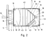
- FIG. 2 shows the inverter motor 1 from above.
- the inner housing 3 is connected to the outer housing 2 via a cable passage 16.
- the cable passage 16 serves to pass the connection cables from the terminal box to the motor unit.
- the lid top 17 is bounded by the bevel 21, two lateral side surfaces 45 and the end face of the step, which is formed by planar portions 22, 43 and the end face 20.
- planar portions 22, 43 two openings for cable bushings are introduced in each case, which can be closed by screw plugs 19 or 12 by connecting pieces.
- the first planar region 22 is arranged obliquely to the sides of the connection box attachment 8: the mathematical plane defined by the first planar region 22 in idealization intersects two side surfaces 44, 45 of the connection box attachment 8. Said mathematical plane would cut off a corner of the base surface of the lower part as a cutting plane , Due to the diagonal arrangement of the openings for the cable feedthrough, a cable can be led out of the connection box in various directions without the need to implement the connection box.
- the step protects the area around the openings with a protruding housing along and across the motor axis, thereby relieving the strain on the cable guide.
- the side surface of the step comprises a second planar region 43, in which two further openings for the cable feedthrough are introduced. These openings are closed by screwed connection pieces 12.
- the spigots 12 also fit on the openings in the first planar area 22.
- the second level area 43 is also disposed obliquely to the sides of the junction box boss 8: the mathematical plane defined by the second planar area 43 in idealization intersects two side surfaces 44, 45 of the junction box boss 8. Said mathematical level would cut as a cutting plane a corner of the base of the base.
- the second planar region 43 encloses with the first planar region 22 an angle whose opening angle is 80 °.
- the second planar area covers a semicircle of possible cable ducts emanating from the openings, which has only one subarea in common with the corresponding semicircle of the first planar area.
- the possible cable guides thus cover a segment with an opening angle of well over 180 ° without bending or kinking the connecting cable too much.
- a third planar region in the form of an end face 20 is arranged, in which an opening is formed whose diameter is smaller than that of the openings in the first planar region 22. Accordingly, the opening is closed with a connecting piece 13 which is smaller than the connecting piece 12.
- the connecting piece 13 are just dimensioned so that it can accommodate a cable for data communication.
- the connecting pieces 12 are dimensioned so that they can each accommodate a cable for heavy current to supply a motor in the kW range. Since a cable for data communication is much thinner than a power cable, it can be bent better. It must therefore not necessarily be formed corresponding openings in different directions.
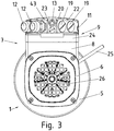
- FIG. 3 shows the inverter motor 1 from the back, so from the side that lies opposite the drive side of the engine.
- a fan 26 is arranged under the fan cover 6, .
- the fan 26 is designed either as a self-ventilator or as a forced cooling fan. It sucks air through the perforated fan cover 6 and blows it through the gap formed by the outer case 2 and the inner case 3. The air thus sweeps over the surface of the inside of the tubular outer housing and finally exits to an annular opening on the drive side.
- a further bore is introduced, which is closed with a locking screw 23.
- a connection piece 13 is alternatively screwed.
- the lid edge 24 of the upper part of the junction box 7 has a surface which is substantially flush with the surface of the side walls of the connecting piece 8.
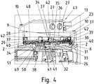
- FIG. 4 shows a section through the terminal box 7.
- the front attachment portion 29 of the terminal box approach 8 has a greater height relative to the outer housing 2 than the rear attachment portion 30.
- the approach edge 28 of the terminal box approach 8 thus has a skew with falling from the drive side of the engine to the fan side height on.
- a step 47 can be formed on the terminal box cover 9 to save space, by providing the lower edge of the terminal box cover 9 with a corresponding bevel.
- the step 47 comprises two plateau surfaces, each having a substantially constant height above the outer housing 2, and an end face connecting the plateau surfaces and extending substantially perpendicular to the motor axis 15. Through the step 47, a cable led out of a connecting piece 12, 13 arranged at the end face is protected at the exit point by parts of the terminal box cover 9.
- a circuit board 35 is arranged with the electronics of the inverter.
- power components 32 are applied in a row transverse to the motor axis.
- the power devices 32 have a contact surface for cooling. These contact surfaces are placed on a support surface 33, which is particularly flat worked in the junction box bottom 31. Between bearing surface 33 and power component 32 thermal compound is applied to further improve the thermal connection to the junction box bottom 31.
- the lower part of the terminal box 7 is made with the outer housing 2 of a casting and the junction box bottom 31 is a portion of the outer housing 2, which is cooled on its inside by a fan 26 driven by the air flow in the air duct 34.
- a fan 26 driven by the air flow in the air duct 34.
- the entire surface of the tubular housing around the motor shaft 15, which carries the fan 26, extending outer housing can be used.
- the power components 32 are therefore thermally well coupled to a large surface, which is also covered by cooling air. Cooling ribs are therefore unnecessary.
- the circuit board 35 is fixed by lugs 40 on a mounting frame 36.
- the mounting frame 36 covers the circuit board 35 to individual openings for connector 38 completely.
- the mounting frame 36 is bolted to the bottom of the base.
- the printed circuit board 35 is sealed after installation in the mounting frame 36 with a heat-conductive potting compound.
- This potting compound establishes a thermal coupling of further electronic components of the printed circuit board 35 with further plan bearing surfaces in the bottom of the junction box. Between the potting compound and the bottom of a protective film is inserted, which is broken at the bearing surfaces.
- the circuit board 35 has a downwardly directed connector 50 to which the windings of the motor unit are connected.
- the connection lines are guided through a connection channel 51, which connects the interior of the connection box with the interior of the stator housing 3.
- the connection channel 51 offers space for Receiving the connector 50 and for receiving an additional DC link capacitor 51.
- This DC link capacitor 51 is dimensioned smaller than that not shown, provided above the mounting frame 36, but is arranged closer to the power devices 32.
- a brim 48 is formed, which has tongues 37.
- another, not shown circuit board for signal electronics and the rectifier and the DC link capacitor of the inverter can be used.
- the tabs 37 snap when inserting the other circuit board with the lugs 42, whereby the other circuit board is held.
- the other circuit board is electrically connected to the circuit board 35 via a matching connector with the connectors 38.
- the further printed circuit board comprises means for connecting the power supply of the converter and means for connecting the data communication lines. Rectifier unit and DC link capacitor are arranged on the other guide plate in the left area and are protected by the increased executed front attachment portion 29 of the terminal box approach 8 even with removed terminal box cover 9.
- FIG. 5 shows a schematic view of another terminal box according to the invention 60 from above.
- a first plateau surface 61 and a second plateau surface 62 are separated by an arcuate end face 68.
- the second plateau surface 62 is here offset by an amount relative to the first plateau surface 61 and is thus further away from the viewer.
- Plateau surface 61, 62 and end face 68 form a step.
- the end face 68 is guided at the ends of the arcuate portion parallel to the side surfaces 69, 70 of the terminal box 60.
- openings 64, 65, 66, 67 are provided for the cable entry into the interior of the connection box 60.
- the openings 64, 65, 66, 67 each have an opening direction, which is symbolized by arrows.
- connection box 60 has a plane of symmetry 63, from which the openings 64, 65, 66, 67 each point away with their opening directions.
- the openings 64, 65, 66, 67 each offer the possibility of a Cable bushing, which is protected by the second plateau surface 62 and the height of the end face 68.
- FIG. 6 shows a sectional view of the inverter motor FIG. 1 with additional electronic options inside the motor connection box.
- the circuit board 35 is attached to the power electronics for motor control on the bottom.
- a further circuit board 80 is attached.
- On this circuit board 80 at least one control electronics, not shown, for bus communication, a connector 83, a rectifier unit 84 of the inverter and an intermediate circuit capacitor 85 is arranged.
- the rectifier unit 84 and the intermediate circuit capacitor 85 are designed for voltages of 400 V and more and for high current strengths of 1 A and more, and therefore have an increased structural dimension. Thus, the additional space provided by the step in the terminal box lid 9 is utilized.
- the connector 83 is formed to match a not shown, another connector on the inside of the terminal box cover 9. This additional connector is plugged by placing the terminal box cover 9 on the terminal box approach 8 in the connector 83.
- the connection cable of the converter motor can be connected to the other connector via cable clamps.
- a third circuit board 81 is connected, preferably via a connector whose connectors are soldered to the respective circuit boards 80, 81.
- the third printed circuit board 81 serves to read out motor variables, in particular operating measured variables, which can be read out for diagnosis via a USB connection 82.
- a USB connection 82 Alternatively, an IR interface or other standard connector is provided.
- FIG. 7 shows an oblique view of the inverter motor FIG. 6 .
- the terminal box lid 9 forms a bow-shaped step and differs from the terminal box lid Figure 1 to 3 only through an additional opening 90, behind which a USB port 82 is arranged for reading operating variables.
- connection piece 95 Shown on the face of the step are the possible mating openings for the grommet: a first diameter cable 91, alternatively a closure 93, a second smaller diameter cable 92, alternatively a closure 94, and a second Connecting piece 95 for data cable with a significantly smaller diameter, alternatively a closure 96.
- the arrangement of the connection piece and closures is merely exemplary, other combinations are also possible.
- connection openings allow compliance with the permissible bending radius of the cable a cable guide that does not increase the interference contour of the inverter motor.
- a connection area is sufficient for the much more flexible data cables.
Landscapes
- Engineering & Computer Science (AREA)
- Power Engineering (AREA)
- Microelectronics & Electronic Packaging (AREA)
- Motor Or Generator Frames (AREA)
- Electric Propulsion And Braking For Vehicles (AREA)
Applications Claiming Priority (3)
| Application Number | Priority Date | Filing Date | Title |
|---|---|---|---|
| DE102007034915A DE102007034915B4 (de) | 2007-07-24 | 2007-07-24 | Motoranschlusskasten und Umrichtermotor |
| EP08784653.1A EP2174404B1 (fr) | 2007-07-24 | 2008-07-08 | Boitier de connexion de moteur et moteur a convertisseur |
| PCT/EP2008/005562 WO2009012883A2 (fr) | 2007-07-24 | 2008-07-08 | Boîtier de connexion de moteur et moteur à convertisseur |
Related Parent Applications (2)
| Application Number | Title | Priority Date | Filing Date |
|---|---|---|---|
| EP08784653.1A Division-Into EP2174404B1 (fr) | 2007-07-24 | 2008-07-08 | Boitier de connexion de moteur et moteur a convertisseur |
| EP08784653.1A Division EP2174404B1 (fr) | 2007-07-24 | 2008-07-08 | Boitier de connexion de moteur et moteur a convertisseur |
Publications (2)
| Publication Number | Publication Date |
|---|---|
| EP3386077A1 true EP3386077A1 (fr) | 2018-10-10 |
| EP3386077B1 EP3386077B1 (fr) | 2020-12-23 |
Family
ID=40155670
Family Applications (4)
| Application Number | Title | Priority Date | Filing Date |
|---|---|---|---|
| EP08784653.1A Active EP2174404B1 (fr) | 2007-07-24 | 2008-07-08 | Boitier de connexion de moteur et moteur a convertisseur |
| EP18000333.7A Active EP3386077B1 (fr) | 2007-07-24 | 2008-07-08 | Boîtier de connexion de moteur et moteur de convertisseur |
| EP12004123.1A Active EP2521248B1 (fr) | 2007-07-24 | 2008-07-08 | Caisse de raccord moteur et moteur à convertisseur |
| EP18000504.3A Active EP3404807B1 (fr) | 2007-07-24 | 2008-07-08 | Boîtier de connexion de moteur et moteur de convertisseur |
Family Applications Before (1)
| Application Number | Title | Priority Date | Filing Date |
|---|---|---|---|
| EP08784653.1A Active EP2174404B1 (fr) | 2007-07-24 | 2008-07-08 | Boitier de connexion de moteur et moteur a convertisseur |
Family Applications After (2)
| Application Number | Title | Priority Date | Filing Date |
|---|---|---|---|
| EP12004123.1A Active EP2521248B1 (fr) | 2007-07-24 | 2008-07-08 | Caisse de raccord moteur et moteur à convertisseur |
| EP18000504.3A Active EP3404807B1 (fr) | 2007-07-24 | 2008-07-08 | Boîtier de connexion de moteur et moteur de convertisseur |
Country Status (10)
| Country | Link |
|---|---|
| US (1) | US8299662B2 (fr) |
| EP (4) | EP2174404B1 (fr) |
| CN (1) | CN101785169B (fr) |
| BR (3) | BR122019001378B1 (fr) |
| DE (1) | DE102007034915B4 (fr) |
| DK (1) | DK3404807T3 (fr) |
| ES (1) | ES2746376T3 (fr) |
| HU (1) | HUE046094T2 (fr) |
| PL (1) | PL3404807T3 (fr) |
| WO (1) | WO2009012883A2 (fr) |
Families Citing this family (24)
| Publication number | Priority date | Publication date | Assignee | Title |
|---|---|---|---|---|
| US8540493B2 (en) | 2003-12-08 | 2013-09-24 | Sta-Rite Industries, Llc | Pump control system and method |
| US7854597B2 (en) | 2004-08-26 | 2010-12-21 | Pentair Water Pool And Spa, Inc. | Pumping system with two way communication |
| US8469675B2 (en) | 2004-08-26 | 2013-06-25 | Pentair Water Pool And Spa, Inc. | Priming protection |
| US8480373B2 (en) | 2004-08-26 | 2013-07-09 | Pentair Water Pool And Spa, Inc. | Filter loading |
| US7845913B2 (en) | 2004-08-26 | 2010-12-07 | Pentair Water Pool And Spa, Inc. | Flow control |
| US8602745B2 (en) | 2004-08-26 | 2013-12-10 | Pentair Water Pool And Spa, Inc. | Anti-entrapment and anti-dead head function |
| US7874808B2 (en) | 2004-08-26 | 2011-01-25 | Pentair Water Pool And Spa, Inc. | Variable speed pumping system and method |
| US7686589B2 (en) | 2004-08-26 | 2010-03-30 | Pentair Water Pool And Spa, Inc. | Pumping system with power optimization |
| MX2011003708A (es) | 2008-10-06 | 2011-06-16 | Pentair Water Pool & Spa Inc | Metodo para operar un sistema de seguridad para alivio de vacio. |
| US9556874B2 (en) | 2009-06-09 | 2017-01-31 | Pentair Flow Technologies, Llc | Method of controlling a pump and motor |
| JP4958988B2 (ja) * | 2010-03-30 | 2012-06-20 | 株式会社豊田自動織機 | 電動圧縮機 |
| PL2453557T3 (pl) | 2010-11-11 | 2023-04-11 | Grundfos Management A/S | Mokry silnik elektryczny i agregat pompowy |
| US8497611B2 (en) | 2011-04-22 | 2013-07-30 | Regal Beloit America, Inc. | Motor end frame |
| US9030066B2 (en) * | 2011-10-31 | 2015-05-12 | Regal Beloit America, Inc. | Electric motor with multiple power access |
| EP2626566B1 (fr) * | 2012-02-08 | 2021-07-28 | Grundfos Holding A/S | Moteur électrique |
| DE102014114837A1 (de) * | 2014-10-13 | 2016-04-14 | Bitzer Kühlmaschinenbau Gmbh | Kältemittelverdichter |
| US10284047B2 (en) | 2016-05-09 | 2019-05-07 | Bluffton Motor Works Llc | Electric motor for washdown, food processing, and chemical applications |
| CN107086727A (zh) * | 2017-06-13 | 2017-08-22 | 浙江佳雪微特电机集团有限责任公司 | 一种大功率永磁无刷水泵电机 |
| EP3817203B1 (fr) | 2019-10-29 | 2021-09-08 | Wilo Se | Fixation détachable d'un convertisseur de fréquence sur un moteur électrique |
| US12587072B2 (en) * | 2021-07-16 | 2026-03-24 | Sew-Eurodrive Gmbh & Co. Kg | Converter motor having a braking resistor |
| DE102021120677A1 (de) * | 2021-08-09 | 2023-02-09 | Ebm-Papst Mulfingen Gmbh & Co. Kg | Elektrische Schnittstelleneinrichtung für einen Elektromotor |
| DE102021214770A1 (de) | 2021-12-21 | 2023-06-22 | Robert Bosch Gesellschaft mit beschränkter Haftung | E-Achsen-Modul eines elektrisch angetriebenen Fahrzeugs |
| DE102022001009B3 (de) | 2022-03-23 | 2023-05-04 | Sew-Eurodrive Gmbh & Co Kg | Antrieb, aufweisend einen Elektromotor, ein Gehäuseteil und ein Elektronikmodul |
| WO2025050120A1 (fr) * | 2023-09-01 | 2025-03-06 | Tau Motors, Inc. | Systèmes et procédés pour ensembles rotor et agencements de refroidissement de rotor |
Citations (13)
| Publication number | Priority date | Publication date | Assignee | Title |
|---|---|---|---|---|
| DE1284505B (de) * | 1962-02-22 | 1968-12-05 | Simon Hans | Anschlusskasten fuer elektrische Geraete |
| DE7342532U (de) * | 1974-03-14 | Bbc Ag | Spannungsumschaltbare, schlagwetter- oder explosionsgeschützte elektrische Maschine | |
| US4475873A (en) * | 1981-02-14 | 1984-10-09 | Grundfos A/S | Wet-motor pump |
| JPH0657067U (ja) * | 1992-12-25 | 1994-08-05 | 株式会社東芝 | 回転電機 |
| DE9415934U1 (de) * | 1994-10-04 | 1994-11-24 | Grundfos As | Pumpenaggregat |
| EP0661793A1 (fr) * | 1993-12-28 | 1995-07-05 | Ebara Corporation | Assemblage de moteur-pompe |
| DE4435510C1 (de) * | 1994-10-04 | 1996-03-07 | Grundfos As | Frequenzumrichtergespeistes Pumpenaggregat |
| EP0858146A2 (fr) * | 1997-02-08 | 1998-08-12 | PHOENIX CONTACT GmbH & Co. | Moteur électrique alimentée par le secteur |
| DE19706188C2 (de) * | 1997-02-17 | 1999-05-06 | Kueppersbusch | Kabelanschlußvorrichtung |
| EP0951131A2 (fr) * | 1998-04-18 | 1999-10-20 | DaimlerChrysler AG | Unité d'entraínement électrique comprenant un moteur électrique et un module électronique |
| DE19956429A1 (de) * | 1999-11-24 | 2001-06-13 | Grundfos As | Elektromotor für insbesondere eine Kreiselpumpe |
| DE102004036281A1 (de) * | 2004-07-27 | 2005-11-10 | Siemens Ag | Elektrischer Kompaktantrieb |
| DE102005041136A1 (de) * | 2005-08-30 | 2007-03-01 | Sew-Eurodrive Gmbh & Co. Kg | Umrichtermotor und Verfahren |
Family Cites Families (16)
| Publication number | Priority date | Publication date | Assignee | Title |
|---|---|---|---|---|
| US4451750A (en) * | 1981-02-03 | 1984-05-29 | Elektro-Mechanik Gmbh | Protective arrangement for a plug-connected electric motor sealed against pressure, vapors and radiation |
| US5766026A (en) * | 1994-10-07 | 1998-06-16 | The Whitaker Corporation | Electrical connector assembly with sealed and spring biased electrical component |
| US5613844A (en) * | 1994-11-15 | 1997-03-25 | Walbro Corporation | Submersible electronic drive module |
| US5856717A (en) * | 1997-03-31 | 1999-01-05 | Reliance Electric Industrial Company | Enclosure for an electric motor |
| US6099325A (en) * | 1998-11-05 | 2000-08-08 | Ford Motor Company | Electronic control module for an electric motor |
| DE10006320A1 (de) * | 2000-02-12 | 2001-08-23 | Daimler Chrysler Ag | Elektrische Antriebseinheit aus Elektromotor und Elektronikmodul |
| US6664682B2 (en) * | 2001-02-28 | 2003-12-16 | Reliance Electric Technologies, Llc | Method and apparatus for securing a conduit box to a motor and motor incorporating same |
| DE10302791B4 (de) * | 2002-01-30 | 2016-03-17 | Denso Corporation | Elektrokompressor |
| DE10339340B4 (de) * | 2003-08-25 | 2020-02-20 | Sew-Eurodrive Gmbh & Co Kg | Vorrichtung zur berührungslosen Energieübertragung |
| DK1735893T3 (da) * | 2004-04-01 | 2008-11-24 | Sew Eurodrive Gmbh & Co | Elektromotor og serie af elektromotorer |
| DE102004039682A1 (de) * | 2004-08-16 | 2006-03-30 | Siemens Ag | Anschlussvorrichtung für eine elektrische Maschine |
| DE102004048461A1 (de) * | 2004-10-05 | 2006-04-27 | Siemens Ag | Gehäuse für eine elektrische Maschine |
| CN2753047Y (zh) * | 2004-11-17 | 2006-01-18 | 佳木斯防爆电机研究所 | 起重及冶金用绕线转子三相异步电动机 |
| DE102005022367B4 (de) * | 2005-05-10 | 2021-05-20 | Sew-Eurodrive Gmbh & Co Kg | Berührungslos versorgter Verbraucher und System |
| JP5221935B2 (ja) * | 2007-11-06 | 2013-06-26 | 三菱重工業株式会社 | インバータ一体型電動圧縮機 |
| JP4909961B2 (ja) * | 2008-09-02 | 2012-04-04 | 日立オートモティブシステムズ株式会社 | 電動パワーステアリング用制御装置 |
-
2007
- 2007-07-24 DE DE102007034915A patent/DE102007034915B4/de active Active
-
2008
- 2008-07-08 EP EP08784653.1A patent/EP2174404B1/fr active Active
- 2008-07-08 PL PL18000504T patent/PL3404807T3/pl unknown
- 2008-07-08 EP EP18000333.7A patent/EP3386077B1/fr active Active
- 2008-07-08 EP EP12004123.1A patent/EP2521248B1/fr active Active
- 2008-07-08 BR BR122019001378-0A patent/BR122019001378B1/pt active IP Right Grant
- 2008-07-08 CN CN2008801001076A patent/CN101785169B/zh active Active
- 2008-07-08 BR BR122019001374-8A patent/BR122019001374B1/pt active IP Right Grant
- 2008-07-08 DK DK18000504.3T patent/DK3404807T3/da active
- 2008-07-08 BR BRPI0814128A patent/BRPI0814128A2/pt not_active Application Discontinuation
- 2008-07-08 ES ES18000504T patent/ES2746376T3/es active Active
- 2008-07-08 HU HUE18000504A patent/HUE046094T2/hu unknown
- 2008-07-08 EP EP18000504.3A patent/EP3404807B1/fr active Active
- 2008-07-08 US US12/670,475 patent/US8299662B2/en active Active
- 2008-07-08 WO PCT/EP2008/005562 patent/WO2009012883A2/fr not_active Ceased
Patent Citations (13)
| Publication number | Priority date | Publication date | Assignee | Title |
|---|---|---|---|---|
| DE7342532U (de) * | 1974-03-14 | Bbc Ag | Spannungsumschaltbare, schlagwetter- oder explosionsgeschützte elektrische Maschine | |
| DE1284505B (de) * | 1962-02-22 | 1968-12-05 | Simon Hans | Anschlusskasten fuer elektrische Geraete |
| US4475873A (en) * | 1981-02-14 | 1984-10-09 | Grundfos A/S | Wet-motor pump |
| JPH0657067U (ja) * | 1992-12-25 | 1994-08-05 | 株式会社東芝 | 回転電機 |
| EP0661793A1 (fr) * | 1993-12-28 | 1995-07-05 | Ebara Corporation | Assemblage de moteur-pompe |
| DE4435510C1 (de) * | 1994-10-04 | 1996-03-07 | Grundfos As | Frequenzumrichtergespeistes Pumpenaggregat |
| DE9415934U1 (de) * | 1994-10-04 | 1994-11-24 | Grundfos As | Pumpenaggregat |
| EP0858146A2 (fr) * | 1997-02-08 | 1998-08-12 | PHOENIX CONTACT GmbH & Co. | Moteur électrique alimentée par le secteur |
| DE19706188C2 (de) * | 1997-02-17 | 1999-05-06 | Kueppersbusch | Kabelanschlußvorrichtung |
| EP0951131A2 (fr) * | 1998-04-18 | 1999-10-20 | DaimlerChrysler AG | Unité d'entraínement électrique comprenant un moteur électrique et un module électronique |
| DE19956429A1 (de) * | 1999-11-24 | 2001-06-13 | Grundfos As | Elektromotor für insbesondere eine Kreiselpumpe |
| DE102004036281A1 (de) * | 2004-07-27 | 2005-11-10 | Siemens Ag | Elektrischer Kompaktantrieb |
| DE102005041136A1 (de) * | 2005-08-30 | 2007-03-01 | Sew-Eurodrive Gmbh & Co. Kg | Umrichtermotor und Verfahren |
Also Published As
| Publication number | Publication date |
|---|---|
| CN101785169A (zh) | 2010-07-21 |
| BR122019001378B1 (pt) | 2020-11-17 |
| ES2746376T3 (es) | 2020-03-05 |
| EP2174404B1 (fr) | 2020-01-22 |
| DE102007034915A1 (de) | 2009-02-05 |
| EP2174404A2 (fr) | 2010-04-14 |
| BR122019001374B1 (pt) | 2020-09-29 |
| DK3404807T3 (da) | 2019-09-23 |
| EP3404807A1 (fr) | 2018-11-21 |
| BRPI0814128A2 (pt) | 2015-10-06 |
| CN101785169B (zh) | 2012-10-10 |
| EP2521248A3 (fr) | 2018-01-24 |
| DE102007034915B4 (de) | 2011-01-05 |
| EP3386077B1 (fr) | 2020-12-23 |
| EP2521248A2 (fr) | 2012-11-07 |
| EP3404807B1 (fr) | 2019-07-03 |
| HUE046094T2 (hu) | 2020-01-28 |
| US20100237722A1 (en) | 2010-09-23 |
| WO2009012883A3 (fr) | 2009-07-23 |
| WO2009012883A2 (fr) | 2009-01-29 |
| US8299662B2 (en) | 2012-10-30 |
| EP2521248B1 (fr) | 2019-02-27 |
| PL3404807T3 (pl) | 2019-11-29 |
Similar Documents
| Publication | Publication Date | Title |
|---|---|---|
| EP3404807B1 (fr) | Boîtier de connexion de moteur et moteur de convertisseur | |
| EP2750266B1 (fr) | Groupe motopompe | |
| EP2449671B1 (fr) | Moteur électrique et installation équipée de moteurs électriques | |
| EP1237260B1 (fr) | Moteur à convertisseur et gamme de système d'entraînement | |
| EP2183838B1 (fr) | Capot de ventilateur, moteur à convertisseur et gamme de moteurs à convertisseur | |
| DE102010047762B4 (de) | Umrichtermotor, Umrichter und Kühlkörper | |
| EP2750267B1 (fr) | Groupe motopompe | |
| EP2750268B1 (fr) | Groupe motopompe | |
| EP3369933A1 (fr) | Pompe de circulation de chauffage | |
| DE102012001389B4 (de) | Getriebe mit einem zentralen Gehäuseteil | |
| DE10205927B4 (de) | Elektromotor | |
| EP2807731B1 (fr) | Transmission pourvue d'une partie carter centrale | |
| DE102023000794A1 (de) | Antrieb, aufweisend einen Elektromotor, ein Gehäuseteil und ein Elektronikmodul | |
| WO2025228591A1 (fr) | Transmission comprenant un moteur électrique ayant une boîte de connexion | |
| EP4342057A1 (fr) | Moteur électrique comprenant un carter de stator et une bride de palier | |
| EP4371221A1 (fr) | Moteur de convertisseur doté d'une résistance de freinage | |
| DE102018106803A1 (de) | Elektronikgehäuseanordnung und Verfahren zu deren Bildung |
Legal Events
| Date | Code | Title | Description |
|---|---|---|---|
| PUAI | Public reference made under article 153(3) epc to a published international application that has entered the european phase |
Free format text: ORIGINAL CODE: 0009012 |
|
| STAA | Information on the status of an ep patent application or granted ep patent |
Free format text: STATUS: REQUEST FOR EXAMINATION WAS MADE |
|
| STAA | Information on the status of an ep patent application or granted ep patent |
Free format text: STATUS: EXAMINATION IS IN PROGRESS |
|
| 17P | Request for examination filed |
Effective date: 20180420 |
|
| AC | Divisional application: reference to earlier application |
Ref document number: 2174404 Country of ref document: EP Kind code of ref document: P |
|
| AK | Designated contracting states |
Kind code of ref document: A1 Designated state(s): AT BE BG CH CY CZ DE DK EE ES FI FR GB GR HR HU IE IS IT LI LT LU LV MC MT NL NO PL PT RO SE SI SK TR |
|
| 17Q | First examination report despatched |
Effective date: 20181004 |
|
| R17C | First examination report despatched (corrected) |
Effective date: 20181004 |
|
| RBV | Designated contracting states (corrected) |
Designated state(s): AT BE BG CH CY CZ DE DK EE ES FI FR GB GR HR HU IE IS IT LI LT LU LV MC MT NL NO PL PT RO SE SI SK TR |
|
| GRAP | Despatch of communication of intention to grant a patent |
Free format text: ORIGINAL CODE: EPIDOSNIGR1 |
|
| STAA | Information on the status of an ep patent application or granted ep patent |
Free format text: STATUS: GRANT OF PATENT IS INTENDED |
|
| RIC1 | Information provided on ipc code assigned before grant |
Ipc: H02K 11/33 20160101ALI20200619BHEP Ipc: H02K 5/22 20060101AFI20200619BHEP Ipc: H02K 9/14 20060101ALI20200619BHEP Ipc: H02K 5/20 20060101ALN20200619BHEP |
|
| RIC1 | Information provided on ipc code assigned before grant |
Ipc: H02K 5/20 20060101ALN20200706BHEP Ipc: H02K 11/33 20160101ALI20200706BHEP Ipc: H02K 9/14 20060101ALI20200706BHEP Ipc: H02K 5/22 20060101AFI20200706BHEP |
|
| INTG | Intention to grant announced |
Effective date: 20200723 |
|
| GRAS | Grant fee paid |
Free format text: ORIGINAL CODE: EPIDOSNIGR3 |
|
| GRAA | (expected) grant |
Free format text: ORIGINAL CODE: 0009210 |
|
| STAA | Information on the status of an ep patent application or granted ep patent |
Free format text: STATUS: THE PATENT HAS BEEN GRANTED |
|
| AC | Divisional application: reference to earlier application |
Ref document number: 2174404 Country of ref document: EP Kind code of ref document: P |
|
| AK | Designated contracting states |
Kind code of ref document: B1 Designated state(s): AT BE BG CH CY CZ DE DK EE ES FI FR GB GR HR HU IE IS IT LI LT LU LV MC MT NL NO PL PT RO SE SI SK TR |
|
| REG | Reference to a national code |
Ref country code: GB Ref legal event code: FG4D Free format text: NOT ENGLISH |
|
| REG | Reference to a national code |
Ref country code: DE Ref legal event code: R096 Ref document number: 502008017176 Country of ref document: DE |
|
| REG | Reference to a national code |
Ref country code: AT Ref legal event code: REF Ref document number: 1348671 Country of ref document: AT Kind code of ref document: T Effective date: 20210115 |
|
| REG | Reference to a national code |
Ref country code: IE Ref legal event code: FG4D Free format text: LANGUAGE OF EP DOCUMENT: GERMAN |
|
| PG25 | Lapsed in a contracting state [announced via postgrant information from national office to epo] |
Ref country code: GR Free format text: LAPSE BECAUSE OF FAILURE TO SUBMIT A TRANSLATION OF THE DESCRIPTION OR TO PAY THE FEE WITHIN THE PRESCRIBED TIME-LIMIT Effective date: 20210324 Ref country code: NO Free format text: LAPSE BECAUSE OF FAILURE TO SUBMIT A TRANSLATION OF THE DESCRIPTION OR TO PAY THE FEE WITHIN THE PRESCRIBED TIME-LIMIT Effective date: 20210323 Ref country code: FI Free format text: LAPSE BECAUSE OF FAILURE TO SUBMIT A TRANSLATION OF THE DESCRIPTION OR TO PAY THE FEE WITHIN THE PRESCRIBED TIME-LIMIT Effective date: 20201223 |
|
| REG | Reference to a national code |
Ref country code: NL Ref legal event code: MP Effective date: 20201223 |
|
| PG25 | Lapsed in a contracting state [announced via postgrant information from national office to epo] |
Ref country code: SE Free format text: LAPSE BECAUSE OF FAILURE TO SUBMIT A TRANSLATION OF THE DESCRIPTION OR TO PAY THE FEE WITHIN THE PRESCRIBED TIME-LIMIT Effective date: 20201223 Ref country code: LV Free format text: LAPSE BECAUSE OF FAILURE TO SUBMIT A TRANSLATION OF THE DESCRIPTION OR TO PAY THE FEE WITHIN THE PRESCRIBED TIME-LIMIT Effective date: 20201223 Ref country code: BG Free format text: LAPSE BECAUSE OF FAILURE TO SUBMIT A TRANSLATION OF THE DESCRIPTION OR TO PAY THE FEE WITHIN THE PRESCRIBED TIME-LIMIT Effective date: 20210323 |
|
| PG25 | Lapsed in a contracting state [announced via postgrant information from national office to epo] |
Ref country code: NL Free format text: LAPSE BECAUSE OF FAILURE TO SUBMIT A TRANSLATION OF THE DESCRIPTION OR TO PAY THE FEE WITHIN THE PRESCRIBED TIME-LIMIT Effective date: 20201223 Ref country code: HR Free format text: LAPSE BECAUSE OF FAILURE TO SUBMIT A TRANSLATION OF THE DESCRIPTION OR TO PAY THE FEE WITHIN THE PRESCRIBED TIME-LIMIT Effective date: 20201223 |
|
| REG | Reference to a national code |
Ref country code: LT Ref legal event code: MG9D |
|
| PG25 | Lapsed in a contracting state [announced via postgrant information from national office to epo] |
Ref country code: CZ Free format text: LAPSE BECAUSE OF FAILURE TO SUBMIT A TRANSLATION OF THE DESCRIPTION OR TO PAY THE FEE WITHIN THE PRESCRIBED TIME-LIMIT Effective date: 20201223 Ref country code: EE Free format text: LAPSE BECAUSE OF FAILURE TO SUBMIT A TRANSLATION OF THE DESCRIPTION OR TO PAY THE FEE WITHIN THE PRESCRIBED TIME-LIMIT Effective date: 20201223 Ref country code: LT Free format text: LAPSE BECAUSE OF FAILURE TO SUBMIT A TRANSLATION OF THE DESCRIPTION OR TO PAY THE FEE WITHIN THE PRESCRIBED TIME-LIMIT Effective date: 20201223 Ref country code: SK Free format text: LAPSE BECAUSE OF FAILURE TO SUBMIT A TRANSLATION OF THE DESCRIPTION OR TO PAY THE FEE WITHIN THE PRESCRIBED TIME-LIMIT Effective date: 20201223 Ref country code: PT Free format text: LAPSE BECAUSE OF FAILURE TO SUBMIT A TRANSLATION OF THE DESCRIPTION OR TO PAY THE FEE WITHIN THE PRESCRIBED TIME-LIMIT Effective date: 20210423 Ref country code: RO Free format text: LAPSE BECAUSE OF FAILURE TO SUBMIT A TRANSLATION OF THE DESCRIPTION OR TO PAY THE FEE WITHIN THE PRESCRIBED TIME-LIMIT Effective date: 20201223 |
|
| PG25 | Lapsed in a contracting state [announced via postgrant information from national office to epo] |
Ref country code: PL Free format text: LAPSE BECAUSE OF FAILURE TO SUBMIT A TRANSLATION OF THE DESCRIPTION OR TO PAY THE FEE WITHIN THE PRESCRIBED TIME-LIMIT Effective date: 20201223 |
|
| REG | Reference to a national code |
Ref country code: DE Ref legal event code: R097 Ref document number: 502008017176 Country of ref document: DE |
|
| PG25 | Lapsed in a contracting state [announced via postgrant information from national office to epo] |
Ref country code: IS Free format text: LAPSE BECAUSE OF FAILURE TO SUBMIT A TRANSLATION OF THE DESCRIPTION OR TO PAY THE FEE WITHIN THE PRESCRIBED TIME-LIMIT Effective date: 20210423 |
|
| PLBE | No opposition filed within time limit |
Free format text: ORIGINAL CODE: 0009261 |
|
| STAA | Information on the status of an ep patent application or granted ep patent |
Free format text: STATUS: NO OPPOSITION FILED WITHIN TIME LIMIT |
|
| PG25 | Lapsed in a contracting state [announced via postgrant information from national office to epo] |
Ref country code: DK Free format text: LAPSE BECAUSE OF FAILURE TO SUBMIT A TRANSLATION OF THE DESCRIPTION OR TO PAY THE FEE WITHIN THE PRESCRIBED TIME-LIMIT Effective date: 20201223 |
|
| 26N | No opposition filed |
Effective date: 20210924 |
|
| PG25 | Lapsed in a contracting state [announced via postgrant information from national office to epo] |
Ref country code: ES Free format text: LAPSE BECAUSE OF FAILURE TO SUBMIT A TRANSLATION OF THE DESCRIPTION OR TO PAY THE FEE WITHIN THE PRESCRIBED TIME-LIMIT Effective date: 20201223 |
|
| PG25 | Lapsed in a contracting state [announced via postgrant information from national office to epo] |
Ref country code: SI Free format text: LAPSE BECAUSE OF FAILURE TO SUBMIT A TRANSLATION OF THE DESCRIPTION OR TO PAY THE FEE WITHIN THE PRESCRIBED TIME-LIMIT Effective date: 20201223 |
|
| REG | Reference to a national code |
Ref country code: CH Ref legal event code: PL |
|
| GBPC | Gb: european patent ceased through non-payment of renewal fee |
Effective date: 20210708 |
|
| PG25 | Lapsed in a contracting state [announced via postgrant information from national office to epo] |
Ref country code: MC Free format text: LAPSE BECAUSE OF FAILURE TO SUBMIT A TRANSLATION OF THE DESCRIPTION OR TO PAY THE FEE WITHIN THE PRESCRIBED TIME-LIMIT Effective date: 20201223 |
|
| REG | Reference to a national code |
Ref country code: BE Ref legal event code: MM Effective date: 20210731 |
|
| PG25 | Lapsed in a contracting state [announced via postgrant information from national office to epo] |
Ref country code: LI Free format text: LAPSE BECAUSE OF NON-PAYMENT OF DUE FEES Effective date: 20210731 Ref country code: GB Free format text: LAPSE BECAUSE OF NON-PAYMENT OF DUE FEES Effective date: 20210708 Ref country code: CH Free format text: LAPSE BECAUSE OF NON-PAYMENT OF DUE FEES Effective date: 20210731 |
|
| PG25 | Lapsed in a contracting state [announced via postgrant information from national office to epo] |
Ref country code: IS Free format text: LAPSE BECAUSE OF FAILURE TO SUBMIT A TRANSLATION OF THE DESCRIPTION OR TO PAY THE FEE WITHIN THE PRESCRIBED TIME-LIMIT Effective date: 20210423 Ref country code: LU Free format text: LAPSE BECAUSE OF NON-PAYMENT OF DUE FEES Effective date: 20210708 |
|
| PG25 | Lapsed in a contracting state [announced via postgrant information from national office to epo] |
Ref country code: IE Free format text: LAPSE BECAUSE OF NON-PAYMENT OF DUE FEES Effective date: 20210708 Ref country code: BE Free format text: LAPSE BECAUSE OF NON-PAYMENT OF DUE FEES Effective date: 20210731 |
|
| PG25 | Lapsed in a contracting state [announced via postgrant information from national office to epo] |
Ref country code: CY Free format text: LAPSE BECAUSE OF FAILURE TO SUBMIT A TRANSLATION OF THE DESCRIPTION OR TO PAY THE FEE WITHIN THE PRESCRIBED TIME-LIMIT Effective date: 20201223 |
|
| PG25 | Lapsed in a contracting state [announced via postgrant information from national office to epo] |
Ref country code: HU Free format text: LAPSE BECAUSE OF FAILURE TO SUBMIT A TRANSLATION OF THE DESCRIPTION OR TO PAY THE FEE WITHIN THE PRESCRIBED TIME-LIMIT; INVALID AB INITIO Effective date: 20080708 |
|
| PG25 | Lapsed in a contracting state [announced via postgrant information from national office to epo] |
Ref country code: MT Free format text: LAPSE BECAUSE OF FAILURE TO SUBMIT A TRANSLATION OF THE DESCRIPTION OR TO PAY THE FEE WITHIN THE PRESCRIBED TIME-LIMIT Effective date: 20201223 |
|
| PGFP | Annual fee paid to national office [announced via postgrant information from national office to epo] |
Ref country code: FR Payment date: 20250610 Year of fee payment: 18 |
|
| PGFP | Annual fee paid to national office [announced via postgrant information from national office to epo] |
Ref country code: DE Payment date: 20250731 Year of fee payment: 18 |
|
| PGFP | Annual fee paid to national office [announced via postgrant information from national office to epo] |
Ref country code: IT Payment date: 20250623 Year of fee payment: 18 |
|
| PGFP | Annual fee paid to national office [announced via postgrant information from national office to epo] |
Ref country code: AT Payment date: 20250709 Year of fee payment: 18 |
|
| PG25 | Lapsed in a contracting state [announced via postgrant information from national office to epo] |
Ref country code: TR Free format text: LAPSE BECAUSE OF FAILURE TO SUBMIT A TRANSLATION OF THE DESCRIPTION OR TO PAY THE FEE WITHIN THE PRESCRIBED TIME-LIMIT Effective date: 20201223 |
|
| REG | Reference to a national code |
Ref country code: DE Ref legal event code: R084 Ref document number: 502008017176 Country of ref document: DE |