EP3386152A1 - Procédé, dispositif et système pour réaliser un mécanisme de pulsation - Google Patents
Procédé, dispositif et système pour réaliser un mécanisme de pulsation Download PDFInfo
- Publication number
- EP3386152A1 EP3386152A1 EP16881186.7A EP16881186A EP3386152A1 EP 3386152 A1 EP3386152 A1 EP 3386152A1 EP 16881186 A EP16881186 A EP 16881186A EP 3386152 A1 EP3386152 A1 EP 3386152A1
- Authority
- EP
- European Patent Office
- Prior art keywords
- node
- moment
- switching
- switching node
- identity
- Prior art date
- Legal status (The legal status is an assumption and is not a legal conclusion. Google has not performed a legal analysis and makes no representation as to the accuracy of the status listed.)
- Granted
Links
Images


Classifications
-
- H—ELECTRICITY
- H04—ELECTRIC COMMUNICATION TECHNIQUE
- H04L—TRANSMISSION OF DIGITAL INFORMATION, e.g. TELEGRAPHIC COMMUNICATION
- H04L67/00—Network arrangements or protocols for supporting network services or applications
- H04L67/14—Session management
- H04L67/143—Termination or inactivation of sessions, e.g. event-controlled end of session
- H04L67/145—Termination or inactivation of sessions, e.g. event-controlled end of session avoiding end of session, e.g. keep-alive, heartbeats, resumption message or wake-up for inactive or interrupted session
-
- H—ELECTRICITY
- H04—ELECTRIC COMMUNICATION TECHNIQUE
- H04L—TRANSMISSION OF DIGITAL INFORMATION, e.g. TELEGRAPHIC COMMUNICATION
- H04L67/00—Network arrangements or protocols for supporting network services or applications
- H04L67/01—Protocols
- H04L67/10—Protocols in which an application is distributed across nodes in the network
-
- H—ELECTRICITY
- H04—ELECTRIC COMMUNICATION TECHNIQUE
- H04L—TRANSMISSION OF DIGITAL INFORMATION, e.g. TELEGRAPHIC COMMUNICATION
- H04L43/00—Arrangements for monitoring or testing data switching networks
- H04L43/08—Monitoring or testing based on specific metrics, e.g. QoS, energy consumption or environmental parameters
- H04L43/0823—Errors, e.g. transmission errors
-
- H—ELECTRICITY
- H04—ELECTRIC COMMUNICATION TECHNIQUE
- H04L—TRANSMISSION OF DIGITAL INFORMATION, e.g. TELEGRAPHIC COMMUNICATION
- H04L43/00—Arrangements for monitoring or testing data switching networks
- H04L43/10—Active monitoring, e.g. heartbeat, ping or trace-route
-
- H—ELECTRICITY
- H04—ELECTRIC COMMUNICATION TECHNIQUE
- H04L—TRANSMISSION OF DIGITAL INFORMATION, e.g. TELEGRAPHIC COMMUNICATION
- H04L45/00—Routing or path finding of packets in data switching networks
- H04L45/44—Distributed routing
-
- H—ELECTRICITY
- H04—ELECTRIC COMMUNICATION TECHNIQUE
- H04L—TRANSMISSION OF DIGITAL INFORMATION, e.g. TELEGRAPHIC COMMUNICATION
- H04L49/00—Packet switching elements
- H04L49/10—Packet switching elements characterised by the switching fabric construction
- H04L49/103—Packet switching elements characterised by the switching fabric construction using a shared central buffer; using a shared memory
-
- H—ELECTRICITY
- H04—ELECTRIC COMMUNICATION TECHNIQUE
- H04L—TRANSMISSION OF DIGITAL INFORMATION, e.g. TELEGRAPHIC COMMUNICATION
- H04L67/00—Network arrangements or protocols for supporting network services or applications
- H04L67/50—Network services
- H04L67/56—Provisioning of proxy services
- H04L67/568—Storing data temporarily at an intermediate stage, e.g. caching
-
- H—ELECTRICITY
- H04—ELECTRIC COMMUNICATION TECHNIQUE
- H04L—TRANSMISSION OF DIGITAL INFORMATION, e.g. TELEGRAPHIC COMMUNICATION
- H04L67/00—Network arrangements or protocols for supporting network services or applications
- H04L67/50—Network services
- H04L67/60—Scheduling or organising the servicing of application requests, e.g. requests for application data transmissions using the analysis and optimisation of the required network resources
-
- H—ELECTRICITY
- H04—ELECTRIC COMMUNICATION TECHNIQUE
- H04L—TRANSMISSION OF DIGITAL INFORMATION, e.g. TELEGRAPHIC COMMUNICATION
- H04L47/00—Traffic control in data switching networks
- H04L47/70—Admission control; Resource allocation
- H04L47/82—Miscellaneous aspects
- H04L47/822—Collecting or measuring resource availability data
-
- H—ELECTRICITY
- H04—ELECTRIC COMMUNICATION TECHNIQUE
- H04L—TRANSMISSION OF DIGITAL INFORMATION, e.g. TELEGRAPHIC COMMUNICATION
- H04L67/00—Network arrangements or protocols for supporting network services or applications
- H04L67/50—Network services
- H04L67/51—Discovery or management thereof, e.g. service location protocol [SLP] or web services
Definitions
- the present invention relates to the field of computer technologies, and in particular, to a method, an apparatus, and a system for implementing a heartbeat mechanism.
- a heartbeat mechanism means that a transmit end periodically sends a user-defined heartbeat request (for example, a heartbeat packet or a heartbeat frame), and after receiving the structure, a receive end returns a heartbeat response to the transmit end, so that the transmit end learns that the receive end is "online", so as to determine that the receive end can work properly currently.
- a user-defined heartbeat request for example, a heartbeat packet or a heartbeat frame
- a data synchronization unit may be formed by using a group of nodes on which the multiple copies are stored.
- data synchronization may be performed on the nodes in the data synchronization unit by using a synchronization protocol (for example, the raft protocol).
- a synchronization protocol for example, the raft protocol.
- Embodiments of the present invention provide a method, an apparatus, and a system for implementing a heartbeat mechanism, so as to reduce a quantity of heartbeat responses sent by a node, and reduce unnecessary resource occupation overheads in a distributed database system.
- an embodiment of the present invention provides a method for implementing a heartbeat mechanism, applied to a distributed database system, and including: obtaining, by a switching node, a heartbeat request sent by a first node to a second node, where the heartbeat request includes an identity of the first node and an identity of the second node, and the first node and the second node are different nodes connected to the switching node; recording, by the switching node, a first moment at which the heartbeat request is received; querying, by the switching node according to the identity of the second node and from cached information, a second moment at which the switching node most recently receives a message sent by the second node, where the cached information stores a correspondence between a moment at which the switching node receives a message sent by any node and an identity of the node; and if an absolute value of a difference between the first moment and the second moment
- the switching node may record, in real time, a moment at which a message sent by each node in N nodes passes through the switching node, when a heartbeat request sent by the first node to the second node passes through the switching node, the switching node may determine, by querying a moment at which a message sent by the second node is most recently received, that the second node is available, so as to replace the second node to send a heartbeat response to the first node. Therefore, quantities of times of receiving a heartbeat request and sending a heartbeat response by each node in the N nodes are reduced. This avoids consumption of a large quantity of resources for receiving a large quantity of heartbeat requests and sending a large quantity of heartbeat responses.
- the switching node may directly replace the second node to send a heartbeat response to the first node. That is, based on the heartbeat mechanism in this solution, a complete transmission path of the heartbeat request and the heartbeat response is as follows: the first node-the switching node-the first node. However, based on an existing heartbeat mechanism, a complete transmission path of the heartbeat request and the heartbeat response is as follows: the first node-the switching node-the second node-the switching node-the first node.
- a heartbeat path may be further greatly reduced and a delay of a heartbeat response may be reduced, so as to reduce a fault detection time of an entire distributed database system, and improve reliability of the distributed database system.
- the method further includes: storing, by the switching node, a correspondence between the identity of the first node and the first moment in the cached information.
- the obtaining, by a switching node, a heartbeat request sent by a first node to a second node includes: receiving, by the switching node, a message sent by the first node to the second node, where the message carries the identity of the first node; and parsing, by the switching node, the message, so as to determine that the message is the heartbeat request sent by the first node to the second node.
- the method further includes: if the message is not the heartbeat request sent by the first node to the second node, recording, by the switching node, a third moment at which the message is received; and storing, by the switching node, a correspondence between the identity of the first node and the third moment in the cached information.
- the method further includes: if the absolute value of the difference between the first moment and the second moment is greater than the threshold, forwarding, by the switching node, the heartbeat request to the second node.
- an embodiment of the present invention provides a switching node, applied to a distributed database system, where the switching node is connected to a first node and a second node, and the switching node includes: an obtaining unit, configured to obtain a heartbeat request sent by a first node to a second node, where the heartbeat request includes an identity of the first node and an identity of the second node; a recording unit, configured to record a first moment at which the heartbeat request is received; a query unit, configured to query, according to the identity of the second node and from cached information, a second moment at which the switching node most recently receives a message sent by the second node, where the cached information stores a correspondence between a moment at which the switching node receives a message sent by any node and an identity of the node; and a sending unit, configured to: if an absolute value of a difference between the first moment and the second moment is less than a threshold, send a heartbeat response to the first node.
- the switching node further includes: a storage unit, configured to store a correspondence between the identity of the first node and the first moment in the cached information.
- the switching node further includes a parsing unit, where the obtaining unit is further configured to receive a message sent by the first node to the second node, where the message carries the identity of the first node; and the parsing unit is configured to parse the message, so as to determine that the message is the heartbeat request sent by the first node to the second node.
- the recording unit is further configured to: if the message is not the heartbeat request sent by the first node to the second node, record a third moment at which the message is received; and the storage unit is further configured to store a correspondence between the identity of the first node and the third moment in the cached information.
- the sending unit is further configured to: if the absolute value of the difference between the first moment and the second moment is greater than the threshold, forward the heartbeat request to the second node.
- an embodiment of the present invention provides a switching node, including: a processor, a memory, a bus, and a communications interface, where the memory is configured to store a computer executable instruction, the processor and the memory are connected by using the bus, and when the switching node runs, the processor executes the computer executable instruction stored in the memory, so that the switching node performs the method for implementing a heartbeat mechanism in any one of the first aspect or the possible designs of the first aspect.
- an embodiment of the present invention provides a system for implementing a heartbeat mechanism, including the switching node in any one of the second aspect or the possible designs of the second aspect, or any one of the third aspect or the possible designs of the third aspect, and a first node and a second node that are both connected to the switching node.
- an embodiment of the present invention provides a computer storage medium, configured to store a computer software instruction used by the foregoing switching node, and the computer software instruction includes programs that are designed for the switching node to perform the foregoing aspects.
- names of the switching node, the first node, and the second node impose no limitation on devices or function modules.
- the devices or the function modules may be represented by other names.
- Various devices or function modules shall fall within the scope of protection defined by claims of the present invention and their equivalent technologies, provided that functions of the various devices or function modules are similar to the functions of the devices or function modules in the present invention.
- the switching node may record, in real time, a moment at which a message sent by each node in all nodes passes through the switching node, when a heartbeat request sent by the first node to the second node passes through the switching node, the switching node may determine, by querying a moment at which a message sent by the second node is most recently received, that the second node is available, so as to replace the second node to send a heartbeat response to the first node. Therefore, quantities of times of receiving a heartbeat request and sending a heartbeat response by each node are reduced. This avoids consumption of a large quantity of resources for receiving a large quantity of heartbeat requests and sending a large quantity of heartbeat responses.
- first and second are merely intended for a purpose of description, and shall not be understood as an indication or implication of relative importance or implicit indication of the number of indicated technical features. Therefore, a feature limited by “first” or “second” may explicitly or implicitly include one or more features. In descriptions of the present invention, “multiple” means two or more than two, unless otherwise specified.
- a core principle of a method for implementing a heartbeat mechanism is as follows: All N nodes that are connected to one switching node (for example, a switch or a router) in a topology structure are used as a node group; because all messages (such as a heartbeat request, a heartbeat response, and a service message) sent by the N nodes need to pass through the switching node, that is, the switching node is located on a path through which every two nodes in the N nodes communicate with each other, the switching node may record, in real time, a moment at which a message sent by each node in the N nodes passes through the switching node.
- a switching node for example, a switch or a router
- the switching node may determine, by querying a moment at which a message sent by the second node is most recently received, whether the second node is "alive". If the second node is "alive", the switching node directly returns a heartbeat response to the first node, with no need to forward the heartbeat request to the second node and then return a heartbeat response by the second node by using the switching node.
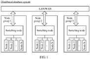
- the method for implementing a heartbeat mechanism may be applied to a distributed database system shown in FIG. 1 .
- All N nodes that are connected to one switching node in a topology structure are used as a node group. All messages sent by the N nodes in the node group need to pass through a switching node in the node group.
- the distributed database system may include multiple node groups. A switching node in each node group is connected to a local area network (Local Area Network, LAN) or a wide area network (Wide Area Network, WAN).
- LAN Local Area Network
- WAN Wide Area Network
- the N nodes in the node group may be an entity device having a storage function, for example, a computer, or may be a function module having a storage function, for example, a disk. This is not limited in this embodiment of the present invention.
- the switching node may record, in real time, a moment at which a message sent by each node in the N nodes passes through the switching node, when a heartbeat request sent by the first node to the second node passes through the switching node, the switching node may determine, by querying a moment at which a message sent by the second node is most recently received, that the second node is available, so as to replace the second node to send a heartbeat response to the first node. Therefore, quantities of times of receiving a heartbeat request and sending a heartbeat response by each node in the N nodes are reduced. This avoids consumption of a large quantity of resources for receiving a large quantity of heartbeat requests and sending a large quantity of heartbeat responses.
- the switching node may directly replace the second node to send a heartbeat response to the first node. That is, based on the heartbeat mechanism in this solution, a complete transmission path of the heartbeat request and the heartbeat response is as follows: the first node-the switching node-the first node. However, based on an existing heartbeat mechanism, a complete transmission path of the heartbeat request and the heartbeat response is as follows: the first node-the switching node-the second node-the switching node-the first node.
- a heartbeat path may be further greatly reduced and a delay of a heartbeat response may be reduced, so as to reduce a fault detection time of an entire distributed database system, and improve reliability of the distributed database system.
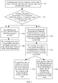
- the following describes a method for implementing a heartbeat mechanism provided in an embodiment of the present invention in detail. As shown in FIG. 2 , the method includes the following steps.
- a switching node receives a message sent by a first node to a second node, where the message carries an identity of the first node.
- the first node and the second node are two different nodes that are in one node group in FIG. 1 and that are connected to the switching node.
- the switching node may receive a message sent by the first node to the second node.
- the message carries the identity of the first node.
- the message described herein may be any message, for example, a heartbeat request, a heartbeat response, or a service message.
- the switching node parses the message, so as to determine whether the message is a heartbeat request sent by the first node to the second node.
- step 102 the switching node parses the message received in step 101, so as to determine whether the message is the heartbeat request sent by the first node to the second node.
- the message may carry an identity of a message type.
- the message type may be specifically a heartbeat request, a heartbeat response, or a service message.
- one or more fields in the message may be reserved to indicate an identity of the message type. Therefore, in step 102, the switching node parses the message received in step 101, so as to obtain an identity of a message type carried in the message, and further determine, according to the identity of a message type, whether the message is the heartbeat request sent by the first node to the second node.
- the message may be sent and received in a packet form.
- the switching node obtains, by parsing first two bits in a header of the packet, the identity of a message type carried in the message, so as to determine, according to the identity of a message type, whether the message is the heartbeat request sent by the first node to the second node. For example, when the identity of a message type is 00, it may be determined that the message is the heartbeat request; when the identify of a message type is 10 in a first frame, it may be determined that the message is a service message. It should be noted that the foregoing method for parsing a message is merely used as an example for description, this embodiment of the present invention imposes no limitation on a manner in which the switching node parses a message.
- the switching node performs the following steps 103a to 106a to query a moment at which a message sent by the second node is most recently received, so as to determine whether the second node is "alive"; or if the message is not the heartbeat request sent by the first node to the second node, the switching node performs the following steps 103b to 104b to record, in real time, a correspondence between a moment at which a message sent by any node is received and an identity of the node.
- the switching node records a first moment at which the heartbeat request is received.
- the heartbeat request includes an identity of the first node and an identity of the second node.
- the heartbeat request further includes the identity of the second node, which is used to instruct the first node to send a heartbeat request to the second node.
- a moment at which the heartbeat request is received and that is recorded by switching node is the first moment.
- the first moment may be considered as a moment at which the first node sends the heartbeat request.
- the moment at which the first node sends the heartbeat request may be further carried in the heartbeat request.
- the switching node may use the carried moment at which the first node sends the heartbeat request as the first moment.
- the switching node queries, according to the identity of the second node and from cached information, a second moment at which the switching node most recently receives a message sent by the second node.
- the cached information stores a correspondence between a moment at which the switching node receives a message sent by any node and an identity of the node.
- Table 1 shows the correspondence that is in the cached information and that is between a moment at which the switching node receives a message sent by any node and an identity of the node. Specifically, when the switching node receives a message sent by any node, as described in step 101, because the message carries an identity of a node that sends the message, the switching node may record, in a memory of the switching node, a correspondence between a moment at which a message sent by any node is received and an identity of the node.
- step 104a when the first node sends a heartbeat request to the second node, the switching node may query, from the cached information, a moment at which the switching node most recently receives a message sent by the second node, that is, the second moment.
- the switching node may further update and maintain the cached information described in the foregoing table. For example, the switching node may periodically delete a correspondence between a moment at which a node sends a message and that is at least one day ago relative to a current time and an identity of the node.
- the switching node may record only a correspondence between a moment that each node sends a message and that is closest to a current time and an identity of the node. For example, when receiving, at 19:0:59, a service message sent by a node whose identity is 2, the switching node may update a moment corresponding to a node whose identity is 2 in the first row in Table 1, so that only a correspondence between a moment at which a node sends a message and that is most closest to a current time and an identity of the node is stored in the cached information.
- a correspondence between the identity of the first node and the first moment may be further stored in the cached information indicates that the first node is available at the first moment, so that when subsequently receiving a heartbeat request sent to the first node, the switching node may obtain, in a timely manner and from the cached information, a first moment at which a message sent by the first node is most recently received.
- the switching node If an absolute value of a difference between the first moment and the second moment is less than a threshold, the switching node sends a heartbeat response to the first node.
- step 105a if the absolute value of the difference between the first moment obtained in step 103a and the second moment obtained in step 104a is less than the threshold, that is,
- the threshold that is,
- the switching node forwards the heartbeat request to the second node.
- step 105a if the absolute value of the difference between the first moment obtained in step 103a and the second moment obtained in step 104a is greater than the threshold, that is,
- the second node After receiving the heartbeat request, if the second node is in an available state, that is, the second node runs properly, the second node feeds back a heartbeat response to the first node by using the switching node; or if the second node is faulty, the second node cannot feed back a heartbeat response to the first node. However, if the first node does not receive, within a specific time period, a heartbeat response sent by the second node, or the first node does not receive a heartbeat response sent by the second node after continually sending a heartbeat request for multiple times, the first node determines that the second node is faulty.
- the switching node records a third moment at which the message is received.
- step 102 if it is determined in step 102 that the message received in step 101 is not the heartbeat request sent by the first node to the second node, for example, the message is a heartbeat response or a service message, in this case, the switching node records a moment at which the message is received, that is, the third moment.
- the switching node stores a correspondence between the identity of the first node and the third moment in the cached information.
- the switching node stores the identity of the first node and the third moment in the cached information, so that when subsequently receiving a heartbeat request sent to the first node, the switching node may obtain, in a timely manner and from the cached information, the third moment at which a message sent by the first node is most recently received.
- the following describes the method for implementing a heartbeat mechanism described in steps 101 to 106a and 101 to 104b is described herein by using a node group 1 in FIG. 1 , as shown in FIG. 3 .
- a switching node may be specifically a switch or a router, and all messages sent by N nodes in the node group 1 need to pass through the switching node.
- a caching unit on the switching node stores cached information. As shown in Table 1, a correspondence between a moment at which the switching node receives a message sent by any node (that is, any node from a node 1 to a node N) and an identity of the node is recorded in the cached information.
- the node 1 may send a message to the switching node.
- the message carries an identity of the node 1, for example, the identity of the node 1 is 1.
- the message herein may be a message of any message type, for example, a heartbeat request or a service message.
- the switching node After receiving the message, the switching node parses the message, so as to determine whether the message is a heartbeat request sent by the node 1.
- the switching node records a first moment T1 at which the heartbeat request is received.
- the heartbeat request includes the identity of the node 1 and an identity of a sending object of the node 1, such as an identity of the node N.
- the switching node queries, according to the identity of the node N and from the cached information in the caching unit, a second moment T2 at which the switching node most recently receives a message sent by the node N.
- ⁇ threshold it indicates that the node N is in an available state not long ago, that is, in an "alive" state, and the switching node sends a heartbeat response to the node 1.
- >threshold the switching node forwards the heartbeat request to the node N.
- the switching node records a third moment T3 at which the message is received, and stores a correspondence between the identity of the node 1 and the third moment T3 in the cached information, so that when subsequently receiving a heartbeat request sent to the node 1, the switching node may obtain, in a timely manner and from the cached information, a moment at which a message sent by the node 1 is most recently received.
- a switching node obtains a heartbeat request sent by a first node to a second node, where the heartbeat request includes an identity of the first node and an identity of the second node; further, the switching node records a first moment at which the heartbeat request is received, and queries, according to the identity of the second node and from cached information, a second moment at which the switching node most recently receives a message sent by the second node, where the cached information stores a correspondence between a moment at which the switching node receives a message sent by any node and an identity of the node; and if an absolute value of a difference between the first moment and the second moment is less than a threshold, the switching node sends a heartbeat response to the first node.
- the switching node may record, in real time, a moment at which a message sent by each node passes through the switching node, when a heartbeat request sent by the first node to the second node passes through the switching node, the switching node may determine, by querying a moment at which a message sent by the second node is most recently received, that the second node is available, so as to replace the second node to send a heartbeat response to the first node. Therefore, quantities of times of receiving heartbeat request and sending heartbeat response by each node are reduced. This avoids consumption of a large quantity of resources for receiving a large quantity of heartbeat requests and sending a large quantity of heartbeat responses.
- FIG. 4 is a schematic structural diagram of a switching node according to an embodiment of the present invention.
- the switching node provided in this embodiment of the present invention may be configured to perform methods for implementing various embodiments of the present invention shown in FIG. 1 to FIG. 3 .
- FIG. 1 to FIG. 3 For ease of description, only a part related to this embodiment of the present invention is shown. For undisclosed technical details, refer to the various embodiments of the present invention shown in FIG. 1 to FIG. 3 .
- the switching node may be specifically a switch, a router, or the like having a programmable capability. This is not limited in the present invention.
- the switching node may be any hardware product that can meet an operation capability requirement.
- the switching node includes:
- the switching node further includes: a storage unit 15, configured to store a correspondence between the identity of the first node and the first moment in the cached information.
- the switching node further includes a parsing unit 16.
- the obtaining unit 11 is further configured to receive a message sent by the first node to the second node, where the message carries the identity of the first node.
- the parsing unit 16 is configured to parse the message, so as to determine that the message is the heartbeat request sent by the first node to the second node.
- the recording unit 12 is further configured to: if the message is not the heartbeat request sent by the first node to the second node, record a third moment at which the message is received.
- the storage unit 15 is further configured to store a correspondence between the identity of the first node and the third moment in the cached information.
- the sending unit 14 is further configured to: if the absolute value of the difference between the first moment and the second moment is greater than the threshold, forward the heartbeat request to the second node.
- FIG. 7 is a schematic structural diagram of hardware of a switching node according to an embodiment of the present invention.
- the switching node includes a processor 21, a communications interface 22, and a memory 23.
- the processor 21, the communications interface 22, and the memory 23 communicate with each other by using a bus 24.
- the memory 23 is configured to store a computer executable instruction.
- the processor 21 and the memory 23 are connected by using the bus 24.
- the processor 21 executes the computer executable instruction stored in the memory 23, so that the switching node performs the method for implementing a heartbeat mechanism shown in FIG. 2 .
- FIG. 2 For a specific method for implementing a heartbeat mechanism, refer to related descriptions in the embodiment shown in FIG. 2 or FIG. 3 , and details are not described herein again.
- the processor 21 may be a central processing unit (English: central processing unit, CPU for short).
- the processor 21 may be another general purpose processor, a digital signal processor (English: digital signal processing, DSP for short), an application-specific integrated circuit (English: application specific integrated circuit, ASIC for short), a field programmable gate array (English: field programmable gate array, FPGA for short) or another programmable logic device, a discrete gate or transistor logic device, a discrete hardware assembly, or the like.
- the general purpose processor may be a microprocessor or this processor may be any conventional processor, or the like.
- the processor 21 is a control center of the switching node.
- the processor 21 performs various functions of the switching node by processing data received by the communications interface 22 and calling software or a program in the memory 23.
- the communications interface 22 may be specifically an interface circuit, and is configured to receive or send a signal in a process of receiving or sending information or a request. After the communications interface 22 receives information sent by a terminal, the processor 21 processes the information. In addition, the communications interface 22 may communicate with a network or another device by means of wireless communications.
- the memory 23 may include a volatile memory (English: volatile memory), for example, a random access memory (English: random-access memory, RAM for short).
- the memory 23 may also include a non-volatile memory (English: non-volatile memory), for example, a read-only memory (English: read-only memory, ROM for short), a flash memory (English: flash memory), a hard disk (English: hard disk drive, HDD for short), or a solid state disk (English: solid-state drive, SSD for short).
- the memory 23 may further include a combination of the foregoing types of memories.
- the processor 21 may run a software program stored in the memory 23, so as to execute various functions and applications of the switching node and perform data processing.
- the memory 23 may be configured to store cached information.
- the cached information stores a correspondence between a moment at which the switching node receives a message sent by any node and an identity of the node.
- the bus 24 may include a data bus, a power bus, a control bus, a signal status bus, and the like. In this embodiment, for a clear description, various buses are represented by the bus 24 in FIG. 7 .
- an embodiment of the present invention further provides a system for implementing a heartbeat mechanism, including any one of the foregoing switching nodes 31, and a first node 32 and a second node 33 that are both connected to the switching node 31.
- a system for implementing a heartbeat mechanism including any one of the foregoing switching nodes 31, and a first node 32 and a second node 33 that are both connected to the switching node 31.
- the switching node 31 may be any node connected to both the first node 32 and the second node 33.
- an existing topology structure between the first node 32 and the second node 33 may be used, and a switch or a router on a communications path between the first node 32 and the second node 33 is used as the switching node 31. In this way, no additional node needs to be introduced to perform functions of the switching node 31.
- the switching node obtains a heartbeat request sent by a first node to a second node, where the heartbeat request includes an identity of the first node and an identity of the second node; further, the switching node records a first moment at which the heartbeat request is received, and queries, according to the identity of the second node and from cached information, a second moment at which the switching node most recently receives a message sent by the second node, where the cached information stores a correspondence between a moment at which the switching node receives a message sent by any node and an identity of the node; and if an absolute value of a difference between the first moment and the second moment is less than a threshold, the switching node sends a heartbeat response to the first node.
- the switching node may record, in real time, a moment at which a message sent by each node passes through the switching node, when a heartbeat request sent by the first node to the second node passes through the switching node, the switching node may determine, by querying a moment at which a message sent by the second node is most recently received, that the second node is available, so as to replace the second node to send a heartbeat response to the first node. Therefore, quantities of times of receiving heartbeat request and sending heartbeat response by each node are reduced. This avoids consumption of a large quantity of resources for receiving a large quantity of heartbeat requests and sending a large quantity of heartbeat responses.
- the disclosed system, apparatus, and method may be implemented in other manners.
- the described apparatus embodiment is merely an example.
- the module or unit division is merely logical function division and may be other division in actual implementation.
- a plurality of units or components may be combined or integrated into another system, or some features may be ignored or not performed.
- the displayed or discussed mutual couplings or direct couplings or communication connections may be implemented by using some interfaces.
- the indirect couplings or communication connections between the apparatuses or units may be implemented in electronic, mechanical, or other forms.
- the units described as separate parts may or may not be physically separate, and parts displayed as units may or may not be physical units, may be located in one position, or may be distributed on a plurality of network units. Some or all of the units may be selected according to actual needs to achieve the objectives of the solutions of the embodiments.
- function units in the embodiments of the present invention may be integrated into one processing unit, or each of the units may exist alone physically, or two or more units are integrated into one unit.
- the integrated unit may be implemented in a form of hardware, or may be implemented in a form of a software function unit.
- the integrated unit When the integrated unit is implemented in the form of a software function unit and sold or used as an independent product, the integrated unit may be stored in a computer-readable storage medium. Based on such an understanding, the technical solutions of the present invention essentially, or the part contributing to the prior art, or all or a part of the technical solutions may be implemented in the form of a software product.
- the software product is stored in a storage medium and includes several instructions for instructing a computer device (which may be a personal computer, a server, or a network device) or a processor (processor) to perform all or a part of the steps of the methods described in the embodiments of the present invention.
- the foregoing storage medium includes: any medium that can store program code, such as a USB flash drive, a removable hard disk, a read-only memory (ROM, Read-Only Memory), a random access memory (RAM, Random Access Memory), a magnetic disk, or an optical disc.
- program code such as a USB flash drive, a removable hard disk, a read-only memory (ROM, Read-Only Memory), a random access memory (RAM, Random Access Memory), a magnetic disk, or an optical disc.
Landscapes
- Engineering & Computer Science (AREA)
- Computer Networks & Wireless Communication (AREA)
- Signal Processing (AREA)
- Health & Medical Sciences (AREA)
- Cardiology (AREA)
- General Health & Medical Sciences (AREA)
- Environmental & Geological Engineering (AREA)
- Hardware Redundancy (AREA)
- Information Retrieval, Db Structures And Fs Structures Therefor (AREA)
- Computer And Data Communications (AREA)
Applications Claiming Priority (2)
| Application Number | Priority Date | Filing Date | Title |
|---|---|---|---|
| CN201511031806.8A CN106936662B (zh) | 2015-12-31 | 2015-12-31 | 一种实现心跳机制的方法、装置及系统 |
| PCT/CN2016/112465 WO2017114397A1 (fr) | 2015-12-31 | 2016-12-27 | Procédé, dispositif et système pour réaliser un mécanisme de pulsation |
Publications (3)
| Publication Number | Publication Date |
|---|---|
| EP3386152A4 EP3386152A4 (fr) | 2018-10-10 |
| EP3386152A1 true EP3386152A1 (fr) | 2018-10-10 |
| EP3386152B1 EP3386152B1 (fr) | 2019-10-09 |
Family
ID=59224595
Family Applications (1)
| Application Number | Title | Priority Date | Filing Date |
|---|---|---|---|
| EP16881186.7A Active EP3386152B1 (fr) | 2015-12-31 | 2016-12-27 | Procédé, dispositif et système pour réaliser un mécanisme de pulsation |
Country Status (4)
| Country | Link |
|---|---|
| US (1) | US11128718B2 (fr) |
| EP (1) | EP3386152B1 (fr) |
| CN (1) | CN106936662B (fr) |
| WO (1) | WO2017114397A1 (fr) |
Cited By (1)
| Publication number | Priority date | Publication date | Assignee | Title |
|---|---|---|---|---|
| CN113411237A (zh) * | 2021-08-18 | 2021-09-17 | 成都丰硕智能数字科技有限公司 | 一种低延迟检测终端状态的方法、存储介质及系统 |
Families Citing this family (10)
| Publication number | Priority date | Publication date | Assignee | Title |
|---|---|---|---|---|
| CN107678918B (zh) * | 2017-09-26 | 2021-06-29 | 郑州云海信息技术有限公司 | 一种分布式文件系统的osd心跳机制设置方法及装置 |
| CN108804119A (zh) * | 2018-04-28 | 2018-11-13 | 北京金山云网络技术有限公司 | 配置更新方法、装置、系统、配置中心、应用节点及介质 |
| CN112995254B (zh) * | 2019-12-13 | 2022-07-19 | 北京金山云网络技术有限公司 | 传输心跳信息的方法、设备、系统、装置及组件 |
| CN113805788B (zh) | 2020-06-12 | 2024-04-09 | 华为技术有限公司 | 一种分布式存储系统及其异常处理方法和相关装置 |
| CN112671835B (zh) * | 2020-12-07 | 2022-08-09 | 深圳市晨北科技有限公司 | 一种请求处理的方法、装置、系统及存储介质 |
| CN114860740B (zh) * | 2021-01-20 | 2025-07-29 | 清华大学 | 基于可编程交换机的分布式事务处理方法、装置和系统 |
| CN113014446B (zh) * | 2021-02-10 | 2022-09-16 | 北京字跳网络技术有限公司 | 异常离线用户检测方法、装置、服务器、存储介质和系统 |
| CN114866395B (zh) * | 2022-04-29 | 2024-03-22 | 中国建设银行股份有限公司 | 多组分布式一致性协议集群心跳通讯方法及装置 |
| CN115242820B (zh) * | 2022-07-25 | 2025-05-13 | 济南浪潮数据技术有限公司 | 一种集群节点故障处理方法、装置、设备及介质 |
| CN115333983B (zh) * | 2022-08-16 | 2023-10-10 | 超聚变数字技术有限公司 | 心跳管理方法及节点 |
Family Cites Families (17)
| Publication number | Priority date | Publication date | Assignee | Title |
|---|---|---|---|---|
| US7451359B1 (en) | 2002-11-27 | 2008-11-11 | Oracle International Corp. | Heartbeat mechanism for cluster systems |
| US7383313B2 (en) * | 2003-11-05 | 2008-06-03 | Hitachi, Ltd. | Apparatus and method of heartbeat mechanism using remote mirroring link for multiple storage system |
| US7912950B1 (en) * | 2007-07-09 | 2011-03-22 | ByteSphere Technologies, LLC | Adaptive polling facility for network monitoring system |
| CN101115313B (zh) * | 2007-08-23 | 2011-01-19 | 中兴通讯股份有限公司 | 一种软心跳检测方法及系统 |
| CN101771579A (zh) * | 2009-01-06 | 2010-07-07 | 鲁逸峰 | 一种p2p流媒体系统中的分布式节点故障检测方法 |
| US8356007B2 (en) * | 2010-10-20 | 2013-01-15 | Microsoft Corporation | Distributed transaction management for database systems with multiversioning |
| GB2499747B (en) * | 2010-11-22 | 2014-04-09 | Seven Networks Inc | Aligning data transfer to optimize connections established for transmission over a wireless network |
| CN102185740B (zh) * | 2011-05-13 | 2013-09-18 | 北京星网锐捷网络技术有限公司 | 心跳检测方法及网络设备 |
| EP2717524A4 (fr) * | 2011-07-01 | 2014-04-23 | Huawei Tech Co Ltd | Procédé de transmission d'un message de pulsation et serveur mandataire de pulsation |
| US8743680B2 (en) | 2011-08-12 | 2014-06-03 | International Business Machines Corporation | Hierarchical network failure handling in a clustered node environment |
| US9244796B2 (en) * | 2011-11-15 | 2016-01-26 | International Business Machines Corporation | Diagnostic heartbeat throttling |
| US9705733B2 (en) * | 2012-08-07 | 2017-07-11 | Ca, Inc. | Systems and methods for throttling polling |
| CN103117901B (zh) * | 2013-02-01 | 2016-06-15 | 华为技术有限公司 | 一种分布式心跳检测方法、装置及系统 |
| WO2014186733A1 (fr) * | 2013-05-16 | 2014-11-20 | Convida Wireless, Llc | Systèmes et procédés de recherche améliorée |
| CN103763155A (zh) * | 2014-01-24 | 2014-04-30 | 国家电网公司 | 分布式云存储系统多服务心跳监测方法 |
| CN104506358A (zh) * | 2014-12-19 | 2015-04-08 | 上海斐讯数据通信技术有限公司 | 基于snmp的网络管理系统及网络管理方法 |
| CN104883279B (zh) * | 2015-04-13 | 2018-05-18 | 中国联合网络通信集团有限公司 | 心跳报文处理方法、设备和系统 |
-
2015
- 2015-12-31 CN CN201511031806.8A patent/CN106936662B/zh active Active
-
2016
- 2016-12-27 EP EP16881186.7A patent/EP3386152B1/fr active Active
- 2016-12-27 WO PCT/CN2016/112465 patent/WO2017114397A1/fr not_active Ceased
-
2018
- 2018-06-29 US US16/023,532 patent/US11128718B2/en active Active
Cited By (1)
| Publication number | Priority date | Publication date | Assignee | Title |
|---|---|---|---|---|
| CN113411237A (zh) * | 2021-08-18 | 2021-09-17 | 成都丰硕智能数字科技有限公司 | 一种低延迟检测终端状态的方法、存储介质及系统 |
Also Published As
| Publication number | Publication date |
|---|---|
| EP3386152B1 (fr) | 2019-10-09 |
| CN106936662B (zh) | 2020-01-31 |
| US20180309835A1 (en) | 2018-10-25 |
| WO2017114397A1 (fr) | 2017-07-06 |
| EP3386152A4 (fr) | 2018-10-10 |
| CN106936662A (zh) | 2017-07-07 |
| US11128718B2 (en) | 2021-09-21 |
Similar Documents
| Publication | Publication Date | Title |
|---|---|---|
| EP3386152B1 (fr) | Procédé, dispositif et système pour réaliser un mécanisme de pulsation | |
| US20220141121A1 (en) | Path determining method and related device | |
| CN104980519A (zh) | 多机房存储系统 | |
| US20170235519A1 (en) | Device Management Method, Device, and Device Management Controller | |
| US12566642B2 (en) | Node management method, device and apparatus, storage medium, and system | |
| EP3534579A1 (fr) | Transmission de paquet | |
| CN111061431B (zh) | 一种分布式存储方法、服务器及客户端 | |
| CN109344014A (zh) | 一种主备切换方法、装置及通信设备 | |
| AU2021383892B2 (en) | Switching processing method and apparatus, and communication device | |
| WO2018090677A1 (fr) | Procédé, dispositif et système de traitement pour anomalie de composant nf | |
| US20190158627A1 (en) | Method and device for generating forwarding information | |
| WO2022166582A1 (fr) | Procédé de gestion de réseau, appareil, dispositif, et support de stockage lisible par ordinateur | |
| WO2023193498A1 (fr) | Procédé d'évaluation de fiabilité de réseau, appareil, dispositif informatique, et support de stockage | |
| US20180219971A1 (en) | Service Processing Method and Device | |
| US11190432B2 (en) | Method and first node for managing transmission of probe messages | |
| CN112491951B (zh) | 对等网络中的请求处理方法、服务器及存储介质 | |
| CN112052104B (zh) | 基于多机房实现的消息队列的管理方法及电子设备 | |
| US12132657B1 (en) | Systems and methods for data flow between mobile applications and customer premises equipment, using a consistent server hash | |
| CN106712990B (zh) | 服务部署方法和系统 | |
| US20220353142A1 (en) | Data Obtaining Method and Apparatus | |
| US10397978B2 (en) | Method and system for signaling optimization of IP connection over a mobile-radio network | |
| EP4575823A1 (fr) | Procédé et système d'acquisition d'informations d'états de noeuds, et appareil associé | |
| EP3629194A1 (fr) | Récupération à la demande d'informations à partir de bases de données | |
| CN117097801A (zh) | 访问方法及系统、cdn节点、电子设备及存储介质 | |
| HK40091754A (en) | Switching processing method and apparatus, and communication device |
Legal Events
| Date | Code | Title | Description |
|---|---|---|---|
| STAA | Information on the status of an ep patent application or granted ep patent |
Free format text: STATUS: THE INTERNATIONAL PUBLICATION HAS BEEN MADE |
|
| PUAI | Public reference made under article 153(3) epc to a published international application that has entered the european phase |
Free format text: ORIGINAL CODE: 0009012 |
|
| STAA | Information on the status of an ep patent application or granted ep patent |
Free format text: STATUS: REQUEST FOR EXAMINATION WAS MADE |
|
| 17P | Request for examination filed |
Effective date: 20180703 |
|
| A4 | Supplementary search report drawn up and despatched |
Effective date: 20180828 |
|
| AK | Designated contracting states |
Kind code of ref document: A1 Designated state(s): AL AT BE BG CH CY CZ DE DK EE ES FI FR GB GR HR HU IE IS IT LI LT LU LV MC MK MT NL NO PL PT RO RS SE SI SK SM TR |
|
| AX | Request for extension of the european patent |
Extension state: BA ME |
|
| DAV | Request for validation of the european patent (deleted) | ||
| DAX | Request for extension of the european patent (deleted) | ||
| GRAP | Despatch of communication of intention to grant a patent |
Free format text: ORIGINAL CODE: EPIDOSNIGR1 |
|
| STAA | Information on the status of an ep patent application or granted ep patent |
Free format text: STATUS: GRANT OF PATENT IS INTENDED |
|
| RIC1 | Information provided on ipc code assigned before grant |
Ipc: H04L 29/08 20060101ALI20190429BHEP Ipc: H04L 12/26 20060101AFI20190429BHEP |
|
| INTG | Intention to grant announced |
Effective date: 20190524 |
|
| GRAS | Grant fee paid |
Free format text: ORIGINAL CODE: EPIDOSNIGR3 |
|
| GRAA | (expected) grant |
Free format text: ORIGINAL CODE: 0009210 |
|
| STAA | Information on the status of an ep patent application or granted ep patent |
Free format text: STATUS: THE PATENT HAS BEEN GRANTED |
|
| AK | Designated contracting states |
Kind code of ref document: B1 Designated state(s): AL AT BE BG CH CY CZ DE DK EE ES FI FR GB GR HR HU IE IS IT LI LT LU LV MC MK MT NL NO PL PT RO RS SE SI SK SM TR |
|
| REG | Reference to a national code |
Ref country code: GB Ref legal event code: FG4D |
|
| REG | Reference to a national code |
Ref country code: CH Ref legal event code: EP |
|
| REG | Reference to a national code |
Ref country code: IE Ref legal event code: FG4D |
|
| REG | Reference to a national code |
Ref country code: DE Ref legal event code: R096 Ref document number: 602016022365 Country of ref document: DE |
|
| REG | Reference to a national code |
Ref country code: AT Ref legal event code: REF Ref document number: 1190111 Country of ref document: AT Kind code of ref document: T Effective date: 20191115 |
|
| REG | Reference to a national code |
Ref country code: NL Ref legal event code: MP Effective date: 20191009 |
|
| REG | Reference to a national code |
Ref country code: LT Ref legal event code: MG4D |
|
| REG | Reference to a national code |
Ref country code: AT Ref legal event code: MK05 Ref document number: 1190111 Country of ref document: AT Kind code of ref document: T Effective date: 20191009 |
|
| PG25 | Lapsed in a contracting state [announced via postgrant information from national office to epo] |
Ref country code: NO Free format text: LAPSE BECAUSE OF FAILURE TO SUBMIT A TRANSLATION OF THE DESCRIPTION OR TO PAY THE FEE WITHIN THE PRESCRIBED TIME-LIMIT Effective date: 20200109 Ref country code: AT Free format text: LAPSE BECAUSE OF FAILURE TO SUBMIT A TRANSLATION OF THE DESCRIPTION OR TO PAY THE FEE WITHIN THE PRESCRIBED TIME-LIMIT Effective date: 20191009 Ref country code: PL Free format text: LAPSE BECAUSE OF FAILURE TO SUBMIT A TRANSLATION OF THE DESCRIPTION OR TO PAY THE FEE WITHIN THE PRESCRIBED TIME-LIMIT Effective date: 20191009 Ref country code: ES Free format text: LAPSE BECAUSE OF FAILURE TO SUBMIT A TRANSLATION OF THE DESCRIPTION OR TO PAY THE FEE WITHIN THE PRESCRIBED TIME-LIMIT Effective date: 20191009 Ref country code: LT Free format text: LAPSE BECAUSE OF FAILURE TO SUBMIT A TRANSLATION OF THE DESCRIPTION OR TO PAY THE FEE WITHIN THE PRESCRIBED TIME-LIMIT Effective date: 20191009 Ref country code: PT Free format text: LAPSE BECAUSE OF FAILURE TO SUBMIT A TRANSLATION OF THE DESCRIPTION OR TO PAY THE FEE WITHIN THE PRESCRIBED TIME-LIMIT Effective date: 20200210 Ref country code: NL Free format text: LAPSE BECAUSE OF FAILURE TO SUBMIT A TRANSLATION OF THE DESCRIPTION OR TO PAY THE FEE WITHIN THE PRESCRIBED TIME-LIMIT Effective date: 20191009 Ref country code: GR Free format text: LAPSE BECAUSE OF FAILURE TO SUBMIT A TRANSLATION OF THE DESCRIPTION OR TO PAY THE FEE WITHIN THE PRESCRIBED TIME-LIMIT Effective date: 20200110 Ref country code: BG Free format text: LAPSE BECAUSE OF FAILURE TO SUBMIT A TRANSLATION OF THE DESCRIPTION OR TO PAY THE FEE WITHIN THE PRESCRIBED TIME-LIMIT Effective date: 20200109 Ref country code: FI Free format text: LAPSE BECAUSE OF FAILURE TO SUBMIT A TRANSLATION OF THE DESCRIPTION OR TO PAY THE FEE WITHIN THE PRESCRIBED TIME-LIMIT Effective date: 20191009 Ref country code: LV Free format text: LAPSE BECAUSE OF FAILURE TO SUBMIT A TRANSLATION OF THE DESCRIPTION OR TO PAY THE FEE WITHIN THE PRESCRIBED TIME-LIMIT Effective date: 20191009 Ref country code: SE Free format text: LAPSE BECAUSE OF FAILURE TO SUBMIT A TRANSLATION OF THE DESCRIPTION OR TO PAY THE FEE WITHIN THE PRESCRIBED TIME-LIMIT Effective date: 20191009 |
|
| PG25 | Lapsed in a contracting state [announced via postgrant information from national office to epo] |
Ref country code: HR Free format text: LAPSE BECAUSE OF FAILURE TO SUBMIT A TRANSLATION OF THE DESCRIPTION OR TO PAY THE FEE WITHIN THE PRESCRIBED TIME-LIMIT Effective date: 20191009 Ref country code: RS Free format text: LAPSE BECAUSE OF FAILURE TO SUBMIT A TRANSLATION OF THE DESCRIPTION OR TO PAY THE FEE WITHIN THE PRESCRIBED TIME-LIMIT Effective date: 20191009 Ref country code: IS Free format text: LAPSE BECAUSE OF FAILURE TO SUBMIT A TRANSLATION OF THE DESCRIPTION OR TO PAY THE FEE WITHIN THE PRESCRIBED TIME-LIMIT Effective date: 20200224 |
|
| PG25 | Lapsed in a contracting state [announced via postgrant information from national office to epo] |
Ref country code: AL Free format text: LAPSE BECAUSE OF FAILURE TO SUBMIT A TRANSLATION OF THE DESCRIPTION OR TO PAY THE FEE WITHIN THE PRESCRIBED TIME-LIMIT Effective date: 20191009 |
|
| REG | Reference to a national code |
Ref country code: DE Ref legal event code: R097 Ref document number: 602016022365 Country of ref document: DE |
|
| PG2D | Information on lapse in contracting state deleted |
Ref country code: IS |
|
| PG25 | Lapsed in a contracting state [announced via postgrant information from national office to epo] |
Ref country code: CZ Free format text: LAPSE BECAUSE OF FAILURE TO SUBMIT A TRANSLATION OF THE DESCRIPTION OR TO PAY THE FEE WITHIN THE PRESCRIBED TIME-LIMIT Effective date: 20191009 Ref country code: EE Free format text: LAPSE BECAUSE OF FAILURE TO SUBMIT A TRANSLATION OF THE DESCRIPTION OR TO PAY THE FEE WITHIN THE PRESCRIBED TIME-LIMIT Effective date: 20191009 Ref country code: DK Free format text: LAPSE BECAUSE OF FAILURE TO SUBMIT A TRANSLATION OF THE DESCRIPTION OR TO PAY THE FEE WITHIN THE PRESCRIBED TIME-LIMIT Effective date: 20191009 Ref country code: RO Free format text: LAPSE BECAUSE OF FAILURE TO SUBMIT A TRANSLATION OF THE DESCRIPTION OR TO PAY THE FEE WITHIN THE PRESCRIBED TIME-LIMIT Effective date: 20191009 Ref country code: IS Free format text: LAPSE BECAUSE OF FAILURE TO SUBMIT A TRANSLATION OF THE DESCRIPTION OR TO PAY THE FEE WITHIN THE PRESCRIBED TIME-LIMIT Effective date: 20200209 |
|
| REG | Reference to a national code |
Ref country code: CH Ref legal event code: PL |
|
| PLBE | No opposition filed within time limit |
Free format text: ORIGINAL CODE: 0009261 |
|
| STAA | Information on the status of an ep patent application or granted ep patent |
Free format text: STATUS: NO OPPOSITION FILED WITHIN TIME LIMIT |
|
| REG | Reference to a national code |
Ref country code: BE Ref legal event code: MM Effective date: 20191231 |
|
| PG25 | Lapsed in a contracting state [announced via postgrant information from national office to epo] |
Ref country code: IT Free format text: LAPSE BECAUSE OF FAILURE TO SUBMIT A TRANSLATION OF THE DESCRIPTION OR TO PAY THE FEE WITHIN THE PRESCRIBED TIME-LIMIT Effective date: 20191009 Ref country code: SK Free format text: LAPSE BECAUSE OF FAILURE TO SUBMIT A TRANSLATION OF THE DESCRIPTION OR TO PAY THE FEE WITHIN THE PRESCRIBED TIME-LIMIT Effective date: 20191009 Ref country code: MC Free format text: LAPSE BECAUSE OF FAILURE TO SUBMIT A TRANSLATION OF THE DESCRIPTION OR TO PAY THE FEE WITHIN THE PRESCRIBED TIME-LIMIT Effective date: 20191009 Ref country code: SM Free format text: LAPSE BECAUSE OF FAILURE TO SUBMIT A TRANSLATION OF THE DESCRIPTION OR TO PAY THE FEE WITHIN THE PRESCRIBED TIME-LIMIT Effective date: 20191009 |
|
| 26N | No opposition filed |
Effective date: 20200710 |
|
| PG25 | Lapsed in a contracting state [announced via postgrant information from national office to epo] |
Ref country code: FR Free format text: LAPSE BECAUSE OF NON-PAYMENT OF DUE FEES Effective date: 20191231 Ref country code: IE Free format text: LAPSE BECAUSE OF NON-PAYMENT OF DUE FEES Effective date: 20191227 Ref country code: LU Free format text: LAPSE BECAUSE OF NON-PAYMENT OF DUE FEES Effective date: 20191227 |
|
| PG25 | Lapsed in a contracting state [announced via postgrant information from national office to epo] |
Ref country code: LI Free format text: LAPSE BECAUSE OF NON-PAYMENT OF DUE FEES Effective date: 20191231 Ref country code: SI Free format text: LAPSE BECAUSE OF FAILURE TO SUBMIT A TRANSLATION OF THE DESCRIPTION OR TO PAY THE FEE WITHIN THE PRESCRIBED TIME-LIMIT Effective date: 20191009 Ref country code: CH Free format text: LAPSE BECAUSE OF NON-PAYMENT OF DUE FEES Effective date: 20191231 Ref country code: BE Free format text: LAPSE BECAUSE OF NON-PAYMENT OF DUE FEES Effective date: 20191231 |
|
| PG25 | Lapsed in a contracting state [announced via postgrant information from national office to epo] |
Ref country code: CY Free format text: LAPSE BECAUSE OF FAILURE TO SUBMIT A TRANSLATION OF THE DESCRIPTION OR TO PAY THE FEE WITHIN THE PRESCRIBED TIME-LIMIT Effective date: 20191009 |
|
| PG25 | Lapsed in a contracting state [announced via postgrant information from national office to epo] |
Ref country code: MT Free format text: LAPSE BECAUSE OF FAILURE TO SUBMIT A TRANSLATION OF THE DESCRIPTION OR TO PAY THE FEE WITHIN THE PRESCRIBED TIME-LIMIT Effective date: 20191009 Ref country code: HU Free format text: LAPSE BECAUSE OF FAILURE TO SUBMIT A TRANSLATION OF THE DESCRIPTION OR TO PAY THE FEE WITHIN THE PRESCRIBED TIME-LIMIT; INVALID AB INITIO Effective date: 20161227 |
|
| GBPC | Gb: european patent ceased through non-payment of renewal fee |
Effective date: 20201227 |
|
| REG | Reference to a national code |
Ref country code: DE Ref legal event code: R079 Ref document number: 602016022365 Country of ref document: DE Free format text: PREVIOUS MAIN CLASS: H04L0012260000 Ipc: H04L0043000000 |
|
| PG25 | Lapsed in a contracting state [announced via postgrant information from national office to epo] |
Ref country code: GB Free format text: LAPSE BECAUSE OF NON-PAYMENT OF DUE FEES Effective date: 20201227 |
|
| PG25 | Lapsed in a contracting state [announced via postgrant information from national office to epo] |
Ref country code: TR Free format text: LAPSE BECAUSE OF FAILURE TO SUBMIT A TRANSLATION OF THE DESCRIPTION OR TO PAY THE FEE WITHIN THE PRESCRIBED TIME-LIMIT Effective date: 20191009 |
|
| PG25 | Lapsed in a contracting state [announced via postgrant information from national office to epo] |
Ref country code: MK Free format text: LAPSE BECAUSE OF FAILURE TO SUBMIT A TRANSLATION OF THE DESCRIPTION OR TO PAY THE FEE WITHIN THE PRESCRIBED TIME-LIMIT Effective date: 20191009 |
|
| PGFP | Annual fee paid to national office [announced via postgrant information from national office to epo] |
Ref country code: DE Payment date: 20251104 Year of fee payment: 10 |