EP3386172A1 - Terminal repliable - Google Patents
Terminal repliable Download PDFInfo
- Publication number
- EP3386172A1 EP3386172A1 EP16881254.3A EP16881254A EP3386172A1 EP 3386172 A1 EP3386172 A1 EP 3386172A1 EP 16881254 A EP16881254 A EP 16881254A EP 3386172 A1 EP3386172 A1 EP 3386172A1
- Authority
- EP
- European Patent Office
- Prior art keywords
- fixed member
- foldable terminal
- sliding
- terminal according
- structural member
- Prior art date
- Legal status (The legal status is an assumption and is not a legal conclusion. Google has not performed a legal analysis and makes no representation as to the accuracy of the status listed.)
- Granted
Links
Images


Classifications
-
- H—ELECTRICITY
- H04—ELECTRIC COMMUNICATION TECHNIQUE
- H04M—TELEPHONIC COMMUNICATION
- H04M1/00—Substation equipment, e.g. for use by subscribers
- H04M1/02—Constructional features of telephone sets
- H04M1/0202—Portable telephone sets, e.g. cordless phones, mobile phones or bar type handsets
- H04M1/0206—Portable telephones comprising a plurality of mechanically joined movable body parts, e.g. hinged housings
- H04M1/0208—Portable telephones comprising a plurality of mechanically joined movable body parts, e.g. hinged housings characterized by the relative motions of the body parts
- H04M1/0214—Foldable telephones, i.e. with body parts pivoting to an open position around an axis parallel to the plane they define in closed position
- H04M1/0216—Foldable in one direction, i.e. using a one degree of freedom hinge
- H04M1/022—The hinge comprising two parallel pivoting axes
-
- G—PHYSICS
- G06—COMPUTING OR CALCULATING; COUNTING
- G06F—ELECTRIC DIGITAL DATA PROCESSING
- G06F1/00—Details not covered by groups G06F3/00 - G06F13/00 and G06F21/00
- G06F1/16—Constructional details or arrangements
-
- G—PHYSICS
- G06—COMPUTING OR CALCULATING; COUNTING
- G06F—ELECTRIC DIGITAL DATA PROCESSING
- G06F1/00—Details not covered by groups G06F3/00 - G06F13/00 and G06F21/00
- G06F1/16—Constructional details or arrangements
- G06F1/1613—Constructional details or arrangements for portable computers
- G06F1/1615—Constructional details or arrangements for portable computers with several enclosures having relative motions, each enclosure supporting at least one I/O or computing function
- G06F1/1616—Constructional details or arrangements for portable computers with several enclosures having relative motions, each enclosure supporting at least one I/O or computing function with folding flat displays, e.g. laptop computers or notebooks having a clamshell configuration, with body parts pivoting to an open position around an axis parallel to the plane they define in closed position
-
- G—PHYSICS
- G06—COMPUTING OR CALCULATING; COUNTING
- G06F—ELECTRIC DIGITAL DATA PROCESSING
- G06F1/00—Details not covered by groups G06F3/00 - G06F13/00 and G06F21/00
- G06F1/16—Constructional details or arrangements
- G06F1/1613—Constructional details or arrangements for portable computers
- G06F1/1633—Constructional details or arrangements of portable computers not specific to the type of enclosures covered by groups G06F1/1615 - G06F1/1626
- G06F1/1637—Details related to the display arrangement, including those related to the mounting of the display in the housing
- G06F1/1652—Details related to the display arrangement, including those related to the mounting of the display in the housing the display being flexible, e.g. mimicking a sheet of paper, or rollable
-
- G—PHYSICS
- G06—COMPUTING OR CALCULATING; COUNTING
- G06F—ELECTRIC DIGITAL DATA PROCESSING
- G06F1/00—Details not covered by groups G06F3/00 - G06F13/00 and G06F21/00
- G06F1/16—Constructional details or arrangements
- G06F1/1613—Constructional details or arrangements for portable computers
- G06F1/1633—Constructional details or arrangements of portable computers not specific to the type of enclosures covered by groups G06F1/1615 - G06F1/1626
- G06F1/1675—Miscellaneous details related to the relative movement between the different enclosures or enclosure parts
- G06F1/1681—Details related solely to hinges
-
- H—ELECTRICITY
- H04—ELECTRIC COMMUNICATION TECHNIQUE
- H04M—TELEPHONIC COMMUNICATION
- H04M1/00—Substation equipment, e.g. for use by subscribers
- H04M1/02—Constructional features of telephone sets
-
- H—ELECTRICITY
- H04—ELECTRIC COMMUNICATION TECHNIQUE
- H04M—TELEPHONIC COMMUNICATION
- H04M1/00—Substation equipment, e.g. for use by subscribers
- H04M1/02—Constructional features of telephone sets
- H04M1/0202—Portable telephone sets, e.g. cordless phones, mobile phones or bar type handsets
- H04M1/026—Details of the structure or mounting of specific components
- H04M1/0266—Details of the structure or mounting of specific components for a display module assembly
- H04M1/0268—Details of the structure or mounting of specific components for a display module assembly including a flexible display panel
Definitions
- the present disclosure relates to a field of electronic devices, and more particularly to a foldable terminal.
- a flexible screen Compared with a traditional screen, a flexible screen has obvious advantages.
- the flexible screen is not only slim and light in volume, but also lower in power consumption than an original component, which is beneficial for improving a battery life of a device. Also, based on characteristics of the flexible, such as bendability and good flexibility, durability of the flexible screen is also greatly higher than that of the screen before, and the probability of accidental damage on the device is also reduced.
- the flexible screen is applied to a foldable terminal, so as to obtain a foldable terminal.
- the inventor discovers that there is a radius difference between an outer surface and an inner surface while the terminal is bent.
- the outer surface has a large length at a bending location, such that wrinkles tend to appear at the bending location of the terminal when the terminal is unfolded.
- An objective of the present disclosure is to provide a foldable terminal, which will not be wrinkled when being unfolded.
- a foldable terminal including a body and a flexible screen assembly.
- the body includes a first structural member, a second structural member and a bending assembly, an end surface of the first structural member defines a first sliding cavity and an end surface of the second structural member defines a second sliding cavity.
- the bending assembly includes a fixed member and two sliding bars, first ends of the two sliding bars are rotatably coupled to two side walls of the fixed member correspondingly, and second ends of the two sliding bars are slidably coupled to the first sliding cavity and the second sliding cavity correspondingly.
- the flexible screen assembly is disposed to a folding inner side surface of the body, and a bending area of the flexible screen assembly is right opposite to the fixed member.
- the fixed member slides in a direction running away from the bending area under push of the bending area.
- the two side walls of the fixed member get close to the end surfaces of the first structural member and the second structural member correspondingly, so as to flatten a folding outer side surface of the body.
- the present disclosure further provides another foldable terminal, including: a body including two structural members and a bending assembly connected between the two structural members, the bending assembly including a fixed member and two sliding bars, first ends of the two sliding bars being rotatably coupled to two side walls, opposite to each other, of the fixed member correspondingly, second ends of the two sliding bars being slidably coupled to the two structural members correspondingly; and a flexible screen assembly disposed to a folding inner side surface of the body, and having a bending area right opposite to the fixed member.
- the fixed member slides in a direction running away from the two structural members under push of the bending area.
- the fixed member gets close to the two structural members, so as to flatten a folding outer side surface of the body.
- a foldable terminal involved in embodiments of the present disclosure can be any device having function of communication and storage, for example, an intelligent device with network function such as a tablet PC, a mobile phone, an electronic reader, a remote control, a personal computer (PC), a laptop, an on-board unit, a network television, a wearable device or the like.
- an intelligent device with network function such as a tablet PC, a mobile phone, an electronic reader, a remote control, a personal computer (PC), a laptop, an on-board unit, a network television, a wearable device or the like.
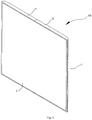
- a foldable terminal 100 is provided by the present disclosure, includes a body 1 and a flexible screen assembly 2.
- the body 1 includes a first structural member 11, a second structural member 12 and a bending assembly 13.
- the first structural member 11 is coupled to the second structural member 12 through the bending assembly 13.
- the flexible screen assembly 2 is disposed to a folding inner side surface 1a of the body 1.
- the bending assembly 13 includes a fixed member 131 and two sliding bars 132. First ends 1321 of the two sliding bars 132 are rotatably coupled to side walls 1313 of the fixed member 131 correspondingly, and second ends 1322 of the two sliding bars 132 are slidably coupled to the first structural member 11 and the second structural member 12 correspondingly, such that the fixed member 131 can have a slidable displacement with respect to the first structural member 11 and the second structural member 12.
- the second ends1322 of the two sliding bars 132 can gradually get close to bottoms of a first sliding cavity 111a and a second sliding cavity 121a correspondingly, so as to enable a length of a folding outer side surface 1b of the body 1 to be reduced gradually, thereby allowing the folding outer side surface 1b of the body 1 to be flat and straight without wrinkles, after the foldable terminal 100 is unfolded.
- a bending area 2a of the flexible screen assembly 2 is in contact with the fixed member 131, such that the bending area 2a of the flexible screen assembly 2 is supported by a flat part, thus improving press sensitivity in the bending area 2a of the flexible screen assembly 2.
- the body 1 also includes a board, and the board is disposed in the first structural member 11 and the second structural member 12.
- the board can also be only disposed in the first structural member 11, or be only disposed in the second structural member 12.
- An external structure of the first structural member 11 is substantially same with an external structure of the second structural member 12.
- Electronic components disposed in the first structural member 11 can be same with or different from electronic components in the second structural member 12.
- the first structural member 11 includes a first inner-end surface 111 and a first outer-end surface 112 disposed opposite to the first inner-end surface 111, as well as a first inner surface 113 and a first outer surface 114 disposed opposite to the first inner surface 113.
- the first structural member 11 defines the first sliding cavity 111a therein, the first sliding cavity 111a extends in a direction from the first inner-end surface 111 to the first outer-end surface 112, and an opening of the first sliding cavity 111a is located in the first inner-end surface 111.
- the second structural member 12 includes a second inner-end surface 121 and a second outer-end surface 122 disposed opposite to the second inner-end surface 121, as well as a second inner surface 123 and a second outer surface 124 disposed opposite to the second inner surface 123.
- the second structural member 12 defines the second sliding cavity 121a therein, the second sliding cavity 121a extends in a direction from the second inner-end surface 121 to the second outer-end surface 122, and an opening of the second sliding cavity 121a is located in the second inner-end surface 121.
- the amount of the first sliding cavity 111a and the amount of the second sliding cavity 121a are corresponding to the amount of the sliding bars 132 of the bending assembly 13.
- the fixed member 131 has a long rectangle shape, so as to conveniently provide a flat support for the bending area 2a of the flexible screen assembly 2.
- the fixed member 131 includes an inner side surface 1311 and an outer side surface 1312 disposed opposite to the inner side surface 1311, two side walls 1313 disposed opposite to each other, as well as an upper-end surface 1314 and a lower-end surface 1315 disposed opposite to the upper-end surface 1314.
- a direction from the upper-end surface 1314 to the lower-end surface 1315 is defined as a longitudinal direction.
- a longitudinal length of the fixed member 131 is same with a longitudinal length of the first inner-end surface 111, so as to ensure a flat support for press on any position in the bending area 2a of the flexible screen assembly 2.
- the two sliding bars 132 are disposed symmetrically, thus further optimizing the structure of the bending assembly 13.
- first ends 1321 of the two sliding bars 132 are rotatably coupled to the two side walls 1313 around the longitudinal direction of the fixed member 131 correspondingly, such that an open-close angle between the two sliding bars 132 can reach 180 degrees.
- the second ends 1322 of the two sliding bars 132 are slidably coupled to the first structural member 11 and the second structural member 12 correspondingly, and located in the first sliding cavity 111a and the second sliding cavity 121a correspondingly.
- the second end 1322 is a rectangular block, and a dimension of the second end 1322 is larger than dimensions of the openings of the first sliding cavity 111a and the second sliding cavity 121a, such that the two second ends 1322 just can be located in the first sliding cavity 111a and the second sliding cavity 121a correspondingly, and cannot be separated from the first sliding cavity 111a and the second sliding cavity 121a.
- the second end 1322 can also have a spherical shape, an oval shape or a trapezoid shape, etc.
- the two sliding bars 132 can also be asymmetrically disposed to the side walls 1313.
- the two sliding bars 132 can be arranged one above the other.
- first outer surface 114 of the first structural member 11, the outer side surface 1312 of the fixed member 131 and the second outer surface 124 of the second structural member 12 form the folding outer side surface 1b of the body 1
- first inner surface 113 of the first structural member 11 and the second inner surface 123 of the second structural member 12 form the folding inner side surface 1a of the body 1.
- the flexible screen assembly 2 is disposed on the folding inner side surface 1a of the body 1, a junction of the first structural member 11 and the second structural member 12 corresponds to the bending area 2a of the flexible screen assembly 2, and the bending area 2a of the flexible screen assembly 2 is in contact with the fixed member 131, such that with an folding angle of the body 1 gradually decreasing, a curvature of the bending area 2a of the flexible screen assembly 2 gradually increases.
- the bending area 2a gradually gets close to the inner side surface 1311 of the fixed member 131, until the bending area 2a is to be close fitted with the inner side surface 1311 of the fixed member 131.
- the fixed member 131 is then ejected in a direction running away from the bending area 2a of the flexible screen assembly 2, so as to increase the length of the folding outer side surface 1b of the body 1, such that the first structural member 11 can be close fitted with the second structural member 12, thus achieving the folding of the foldable terminal 100.
- the flexible screen assembly 2 is always close fitted with the fixed member 131, i.e., a gap between the flexible screen assembly 2 and the inner side surface 1311 of the fixed member 131 is zero, such that when the body 1 is folded, the flexible screen assembly 2 can provide a larger force to eject the fixed member 131, thus further ensuring the folding of the foldable terminal 100.
- a gap can be provided between the flexible screen assembly 2 and the inner side surface 1311 of the fixed member 131, while when the body 1 is gradually folded, the flexible screen assembly 2 gets closer and closer to the inner side surface 1311 of the fixed member 131, until the flexible screen assembly 2 is in contact with the inner side surface 1311 of the fixed member 131.
- the first structural member 11 and/or the second structural member 12 are gradually rotated inwards, so as to drive the sliding bar 132 to rotate relative to the fixed member 131, such that the folding angle of the body 1 gradually decreases, and the curvature of the bending area 2a of the flexible screen assembly 2 gradually increases.
- the bending area 2a is gradually close fitted with the inner side surface 1311 of the fixed member 131, so as to gradually increase the external force pushing the fixed member 131, such that the fixed member 131 is ejected in the direction running away from the bending area 2a of the flexible screen assembly 2, thus increasing the length of the folding outer side surface 1b of the body 1, and enabling the first structural member 11 to be close fitted with the second structural member 12, thereby achieving the folding of the foldable terminal 100.
- the first structural member 11 and/or the second structural member 12 are gradually rotated outwards, so as to drive the sliding bar 132 to rotate relative to the fixed member 131, such that the folding angle of the body 1 gradually increases.
- the second ends 1322 of the sliding bars 132 can gradually get close to the bottoms of the first sliding cavity 111a and the second sliding cavity 121a correspondingly, such that the length of the folding outer side surface 1b of the body 1 gradually decreases.
- the folding outer side surface 1b of the body 1 is a flat and straight surface without wrinkles.
- the bending assembly 13 has two sets of sliding bars 132, a pair of sliding bars 132 is configured as one set, and the first ends 1321 of the two sets of the sliding bars 132 are successively disposed to the fixed member 131 along the longitudinal direction of the fixed member 131.
- the bending assembly 13 is configured to include the two sets of sliding bars 132, thereby further ensuring smoothness when the body 1 is folded.
- the first structural member 11 and the second structural member 12 each have two connection portions with the fixed member 131, and the first structural member 11 and the second structural member 12 each are rotatably coupled to the side wall 1313 through two sliding bars 132. Since one first structural member 11 is slidably coupled to the second ends 1322 of the two sliding bars 132, correspondingly, the first structural member 11 defines two first sliding cavities 111a therein, such that the second ends 1322 of the two sliding bars 132 can be located in the two first sliding cavities 111a correspondingly.
- the second structural member 12 has the same construction.
- the bending assembly 13 By configuring the bending assembly 13 to include the two sets of sliding bars 132, it is possible to improve strength of connection between the first structural member 11 and the fixed member 131 and strength of connection between the second structural member 12 and the fixed member 131, thereby further ensuring the smoothness when the body 1 is folded.
- the side wall 1313 defines a groove 1313a, and the first end 1321 of the sliding bar 132 is rotatably connected in the groove 1313a through a rotating shaft.
- the fixed member 131 is provided with two first rotating holes 1314a, and two openings of the first rotating hole 1314a are located in the upper-end surface 1314 and the lower-end surface 1315 correspondingly.
- the side wall 1313 is successively provided with two sets of symmetrical grooves 1313a in the longitudinal direction, one set of grooves 1313a includes two grooves 1313a, and the two grooves 1313a are located in the two side walls 1313 of the fixed member 131 correspondingly.
- the first end 1321 of the sliding bar 132 is a cup head, so as to rotate in the groove 1313a smoothly.
- the first end 1321 of the sliding bar 132 is provided with a second rotating hole.
- the sliding bar 132 can also be rotatably coupled to the fixed member 131 in following ways: the side wall 1313 defines a spherical groove, the first end 1321 of the sliding bar 132 is a ball head, and the first end 1321 of the sliding bar 132 is connected in the spherical groove in a ball joint manner.
- the end surface of the first structural member 11 is provided with a first baffle plate 111b protruding therefrom and the end face of the second structural member 12 is provided with a second baffle plate 121b protruding therefrom.
- An outer surface of the first baffle plate 111b is flush with the first outer surface 114 of the first structural member 11, and an outer surface of the second baffle plate 121b is flush with the second outer surface 124 of the second structural member 12.
- the bending assembly 13 is located between the first baffle plate 111b and the second baffle plate 121b.
- first baffle plate 111b to the end surface of the first structural member 11 and providing the second baffle plate 121b to the end surface of the second structural member 12, it is possible to further improve the flatness of the folding outer side surface 1b of the body 1.
- a sum of lengths of the first baffle plate 111b and the second baffle plate 121b along a transverse direction of the fixed member 131 is equal to a length of the outer side surface 1312 of the fixed member 131 along the transverse direction of the fixed member 131.
- the first baffle plate 111b protrudes from the first inner-end surface 111, and forms a step together with the first inner-end surface 111.
- the second baffle plate 121b protrudes from the second inner-end surface 121, and forms a step together with the second inner-end surface 121.
- a direction of the first baffle plate 111b from the first inner-end surface 111 to the first outer-end surface 112 is defined as a width of the first baffle plate 111b
- the second baffle plate 121b is similar to the first baffle plate 111b.
- a direction of the fixed member 131 from one side wall 1313 to the other side wall 1313 is defined as a width of the fixed member 131.
- the width of the fixed member 131 is equal to the sum of widths of the first baffle plate 111b and the second baffle plate 121b. When the body is unfolded by 180 degrees, there is no gap in the folding outer side surface 1b of the body 1.
- the sum of the lengths of the first baffle plate 111b and the second baffle plate 121b along the transverse direction of the fixed member 131 can also be less than the length of the outer side surface 1312 of the fixed member 131 along the transverse direction of the fixed member 131.
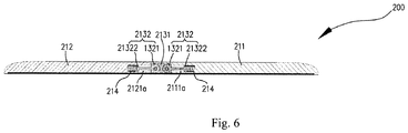
- a first sliding cavity 2111a has a first bottom wall opposite to an opening of the first sliding cavity 2111a
- a second sliding cavity 2121a has a second bottom wall opposite to an opening of the second sliding cavity 2121a
- a bending assembly 213 also includes two elastic members 214, in which one elastic member 214 is elastically connected between a second end 21322 of a sliding bar 2132 and the first bottom wall, and the other elastic member 214 is elastically connected between a second end 21322 of another sliding bar 2132 and the second bottom wall.
- the elastic member 214 is a spring. Specifically, by elastically connecting the elastic member 214 between the second end 21322 of the sliding bar 2132 and the first bottom wall, and also elastically connecting the elastic member 214 between the second end 21322 of another sliding bar 2132 and the second bottom wall, it is possible to enable the first structural member 211 and the second structural member 212 to provide forces to eject the fixed member 2131, thereby further improving reliability in opening or closing the foldable terminal 200.
- the elastic member 214 can also be silica gel.
- the first structural member and the second structural member are gradually rotated inwards respectively, so as to drive the sliding bars to rotate relative to the fixed member, such that the folding angle of the body gradually decreases, and the curvature of the bending area of the flexible screen assembly gradually increases.
- the bending area is gradually close fitted with the inner side surface of the fixed member, such that the fixed member is ejected in the direction running away from the bending area of the flexible screen assembly, thus increasing the length of the folding outer side surface of the body, and enabling the first structural member to be close fitted with the second structural member, thereby achieving the folding of the foldable terminal.
- the foldable terminal When the foldable terminal needs to be unfolded, until the included angle between the bodies is 180 degrees, the first structural member and the second structural member are gradually rotated outwards respectively, so as to drive the sliding bars to rotate relative to the fixed member, such that the folding angle of the body gradually increases.
- the second ends of the sliding bars can gradually get close to the bottoms of the first sliding cavity and the second sliding cavity correspondingly, such that the length of the folding outer side surface of the body gradually decreases.
- the folding outer side surface of the body 1 is flat and straight without wrinkles.
- the first end of the sliding bar is rotatably coupled to the side wall of the fixed member, and the second ends of the two sliding bars are slidably coupled to the first structural member and the second structural member correspondingly, such that a slidable displacement can be provided between the fixed member and the first structural member as well as between the fixed member and the second structural member.
- the second end of the sliding bar can gradually get close to the bottom of the sliding cavity, so as to enable the length of the folding outer side surface of the body to be reduced gradually, thereby allowing the folding outer side surface of the body to be flat and straight without wrinkles, after the foldable terminal is unfolded.
- the bending area of the flexible screen assembly is in contact with the fixed member, such that the bending area of the flexible screen assembly is supported by a flat part, thus improving press sensitivity in the bending area of the flexible screen assembly.
Landscapes
- Engineering & Computer Science (AREA)
- Theoretical Computer Science (AREA)
- Computer Hardware Design (AREA)
- Physics & Mathematics (AREA)
- Human Computer Interaction (AREA)
- General Engineering & Computer Science (AREA)
- General Physics & Mathematics (AREA)
- Signal Processing (AREA)
- Mathematical Physics (AREA)
- Telephone Set Structure (AREA)
- Devices For Indicating Variable Information By Combining Individual Elements (AREA)
Applications Claiming Priority (2)
| Application Number | Priority Date | Filing Date | Title |
|---|---|---|---|
| CN201511026509.4A CN105549689B (zh) | 2015-12-29 | 2015-12-29 | 一种折叠终端 |
| PCT/CN2016/113039 WO2017114465A1 (fr) | 2015-12-29 | 2016-12-29 | Terminal repliable |
Publications (3)
| Publication Number | Publication Date |
|---|---|
| EP3386172A1 true EP3386172A1 (fr) | 2018-10-10 |
| EP3386172A4 EP3386172A4 (fr) | 2018-12-12 |
| EP3386172B1 EP3386172B1 (fr) | 2021-09-01 |
Family
ID=55828919
Family Applications (1)
| Application Number | Title | Priority Date | Filing Date |
|---|---|---|---|
| EP16881254.3A Active EP3386172B1 (fr) | 2015-12-29 | 2016-12-29 | Terminal repliable |
Country Status (6)
| Country | Link |
|---|---|
| US (2) | US10705563B2 (fr) |
| EP (1) | EP3386172B1 (fr) |
| JP (1) | JP6713050B2 (fr) |
| KR (1) | KR102088934B1 (fr) |
| CN (2) | CN107831830B (fr) |
| WO (1) | WO2017114465A1 (fr) |
Cited By (4)
| Publication number | Priority date | Publication date | Assignee | Title |
|---|---|---|---|---|
| WO2019173118A1 (fr) * | 2018-03-09 | 2019-09-12 | Microsoft Technology Licensing, Llc | Dispositif articulé |
| US10754377B2 (en) | 2017-04-05 | 2020-08-25 | Microsoft Technology Licensing, Llc | Hinged device |
| US10761572B1 (en) | 2019-03-25 | 2020-09-01 | Microsoft Technology Licensing, Llc | Hinged device |
| WO2021096536A1 (fr) | 2019-11-17 | 2021-05-20 | Hewlett-Packard Development Company, L.P. | Dispositifs informatiques à charnières rétractables |
Families Citing this family (56)
| Publication number | Priority date | Publication date | Assignee | Title |
|---|---|---|---|---|
| CN107831830B (zh) | 2015-12-29 | 2020-05-05 | Oppo广东移动通信有限公司 | 一种折叠终端 |
| CN108076171B (zh) * | 2016-11-17 | 2020-04-03 | 华为技术有限公司 | 折叠组件及移动终端 |
| CN206584255U (zh) * | 2016-11-17 | 2017-10-24 | 中兴通讯股份有限公司 | 一种移动终端 |
| CN106782091B (zh) * | 2016-12-19 | 2019-06-04 | 上海天马微电子有限公司 | 柔性显示面板及其制造方法、显示设备和便携式终端 |
| US10268245B2 (en) | 2017-01-26 | 2019-04-23 | Guangdong Oppo Mobile Telecommunications Corp., Ltd. | Housing assembly and electronic device |
| CN106790829B (zh) * | 2017-01-26 | 2023-08-04 | Oppo广东移动通信有限公司 | 壳体组件、显示装置及移动终端 |
| CN106559531B (zh) * | 2017-01-26 | 2023-06-16 | Oppo广东移动通信有限公司 | 壳体组件、显示装置及移动终端 |
| CN206918043U (zh) * | 2017-04-19 | 2018-01-23 | 广东欧珀移动通信有限公司 | 转轴组件及可折叠终端 |
| USD908653S1 (en) * | 2017-09-28 | 2021-01-26 | Aristocrat Technologies Australia Pty Limited | LED display module for a gaming display |
| WO2019070293A1 (fr) * | 2017-10-06 | 2019-04-11 | Hewlett-Packard Development Company, L.P. | Ensembles charnières |
| WO2019104463A1 (fr) * | 2017-11-28 | 2019-06-06 | 深圳市柔宇科技有限公司 | Mécanisme de pliage et dispositif électronique |
| CN109936648B (zh) * | 2017-12-18 | 2020-08-07 | 华为技术有限公司 | 转动机构及折叠终端 |
| CN110022386B (zh) | 2018-01-09 | 2021-01-29 | 华为技术有限公司 | 一种可折叠的终端设备 |
| CN108572695B (zh) * | 2018-01-25 | 2021-06-25 | 努比亚技术有限公司 | 连接件、连接机构、显示器及终端 |
| EP3767611A1 (fr) * | 2018-03-12 | 2021-01-20 | Shenzhen Royole Technologies Co., Ltd | Élément pliant et dispositif d'affichage souple |
| CN208581409U (zh) * | 2018-03-29 | 2019-03-05 | 中兴通讯股份有限公司 | 连接装置和电子设备 |
| CN110491285B (zh) * | 2018-05-14 | 2021-11-05 | Oppo广东移动通信有限公司 | 可折叠屏幕和电子装置 |
| CN110611726B (zh) * | 2018-06-14 | 2024-05-28 | 杭州安费诺飞凤通信部品有限公司 | 柔性屏移动终端铰链及柔性屏移动终端 |
| CN109270987B (zh) | 2018-08-29 | 2020-09-11 | 维沃移动通信有限公司 | 一种转轴及具有该转轴的电子设备 |
| CN111327731A (zh) * | 2018-12-14 | 2020-06-23 | 北京小米移动软件有限公司 | 可折叠终端 |
| KR102624839B1 (ko) * | 2018-12-28 | 2024-01-17 | 삼성디스플레이 주식회사 | 표시 장치 |
| CN109671357B (zh) * | 2019-01-08 | 2020-12-11 | 昆山工研院新型平板显示技术中心有限公司 | 显示装置 |
| JP6758439B2 (ja) * | 2019-01-24 | 2020-09-23 | レノボ・シンガポール・プライベート・リミテッド | 携帯用情報機器 |
| US11023009B2 (en) * | 2019-02-12 | 2021-06-01 | Samsung Display Co., Ltd. | Folding member and display device including the same |
| JP6758442B2 (ja) * | 2019-02-26 | 2020-09-23 | レノボ・シンガポール・プライベート・リミテッド | 携帯用情報機器 |
| US11337321B2 (en) | 2019-02-28 | 2022-05-17 | Guangdong Oppo Mobile Telecommunications Corp., Ltd. | Foldable terminal |
| CN109922181B (zh) * | 2019-04-28 | 2021-07-20 | 武汉天马微电子有限公司 | 一种可折叠显示装置的支撑结构及可折叠显示装置 |
| CN111866235B (zh) * | 2019-04-30 | 2026-02-27 | Oppo广东移动通信有限公司 | 折叠装置及电子设备 |
| CN110083209A (zh) * | 2019-05-08 | 2019-08-02 | 珠海格力电器股份有限公司 | 一种折叠屏 |
| CN111930177B (zh) * | 2019-05-13 | 2023-04-04 | 华为技术有限公司 | 一种可折叠的电子设备 |
| KR102172946B1 (ko) * | 2019-06-14 | 2020-11-03 | 베이징 시아오미 모바일 소프트웨어 컴퍼니 리미티드 | 폴딩 장치, 디스플레이 스크린 모듈 및 이동 단말기 |
| CN110286719B (zh) * | 2019-06-28 | 2021-07-16 | 联想(北京)有限公司 | 一种电子设备 |
| CN113366927A (zh) * | 2019-07-15 | 2021-09-07 | 深圳市柔宇科技股份有限公司 | 折叠装置及电子设备 |
| CN110442196B (zh) | 2019-07-30 | 2025-05-06 | 华为技术有限公司 | 转动机构、折叠显示终端 |
| CN112443562B (zh) * | 2019-08-30 | 2022-03-11 | Oppo广东移动通信有限公司 | 电子设备 |
| USD947147S1 (en) * | 2019-10-11 | 2022-03-29 | Lg Electronics Inc. | Electronic display unit |
| USD947149S1 (en) * | 2019-10-11 | 2022-03-29 | Lg Electronics Inc. | Display screen |
| USD947148S1 (en) * | 2019-10-11 | 2022-03-29 | Lg Electronics Inc. | Display screen |
| USD942960S1 (en) * | 2019-10-11 | 2022-02-08 | Lg Electronics Inc. | Electronic display unit |
| KR20210072857A (ko) * | 2019-12-09 | 2021-06-18 | 삼성디스플레이 주식회사 | 표시 장치 |
| CN114424142B (zh) * | 2019-12-17 | 2024-08-13 | 谷歌有限责任公司 | 铰链机构和具有该铰链机构的可折叠设备 |
| CN111105712A (zh) | 2019-12-19 | 2020-05-05 | 武汉华星光电半导体显示技术有限公司 | 显示装置 |
| CN113014696B (zh) * | 2019-12-20 | 2023-08-01 | 中兴通讯股份有限公司 | 折叠终端结构 |
| CN113141424B (zh) * | 2020-01-19 | 2022-10-04 | 北京字节跳动网络技术有限公司 | 折叠支撑结构、显示装置和终端 |
| CN111343310B (zh) | 2020-03-06 | 2021-04-20 | 昆山工研院新型平板显示技术中心有限公司 | 显示装置及移动终端 |
| CN113550975A (zh) * | 2020-04-23 | 2021-10-26 | 深圳市柔宇科技有限公司 | 折叠组件、柔性屏模组和电子设备 |
| CN111968519B (zh) * | 2020-08-31 | 2022-06-17 | 合肥维信诺科技有限公司 | 显示装置 |
| CN112150921B (zh) * | 2020-09-16 | 2022-02-01 | 武汉华星光电半导体显示技术有限公司 | 折叠显示装置 |
| CN112102729B (zh) * | 2020-09-30 | 2022-05-20 | 武汉天马微电子有限公司 | 一种显示装置 |
| KR20220099182A (ko) * | 2021-01-05 | 2022-07-13 | 삼성디스플레이 주식회사 | 표시 장치 |
| CN113056133A (zh) * | 2021-03-11 | 2021-06-29 | 维沃移动通信有限公司 | 电子设备 |
| US11836221B2 (en) * | 2021-03-12 | 2023-12-05 | Google Llc | Systems and methods for refined object estimation from image data |
| CN114550584A (zh) * | 2022-01-25 | 2022-05-27 | 联想(北京)有限公司 | 电子设备 |
| JP7311662B1 (ja) | 2022-03-11 | 2023-07-19 | レノボ・シンガポール・プライベート・リミテッド | 電子機器 |
| CN114576525B (zh) * | 2022-03-31 | 2023-07-21 | 联想(北京)有限公司 | 转动连接结构及电子设备 |
| USD1027888S1 (en) * | 2022-04-18 | 2024-05-21 | Samsung Display Co., Ltd. | Display device |
Family Cites Families (23)
| Publication number | Priority date | Publication date | Assignee | Title |
|---|---|---|---|---|
| CN1476213A (zh) | 2002-08-12 | 2004-02-18 | 浙江华立通信技术有限公司 | 折叠式手机机壳 |
| CN101388918B (zh) * | 2007-09-14 | 2013-10-09 | 京瓷株式会社 | 电子设备 |
| KR101148397B1 (ko) * | 2010-08-17 | 2012-05-23 | 주식회사 팬택 | 휴대 단말기 |
| US9176535B2 (en) * | 2011-06-03 | 2015-11-03 | Microsoft Technology Licensing, Llc | Flexible display flexure assembly |
| CN103167068B (zh) * | 2012-03-26 | 2016-12-28 | 联想(北京)有限公司 | 一种电子终端 |
| KR101958802B1 (ko) * | 2012-07-26 | 2019-03-18 | 삼성디스플레이 주식회사 | 접이식 표시 장치 |
| US8971031B2 (en) * | 2012-08-07 | 2015-03-03 | Creator Technology B.V. | Display system with a flexible display |
| US8804349B2 (en) * | 2012-10-19 | 2014-08-12 | Samsung Display Co., Ltd. | Foldable display device |
| KR102034585B1 (ko) * | 2013-07-09 | 2019-10-21 | 엘지전자 주식회사 | 디스플레이 장치 |
| KR101875855B1 (ko) * | 2014-02-17 | 2018-07-06 | 삼성전자주식회사 | 힌지장치 및 이를 구비하는 폴더블 디스플레이 장치 |
| KR101727971B1 (ko) * | 2014-02-21 | 2017-04-18 | 삼성전자주식회사 | 접철식 기기 |
| KR20150099677A (ko) * | 2014-02-22 | 2015-09-01 | 삼성전자주식회사 | 플렉서블 디스플레이 소자를 구비한 접철식 전자 기기 |
| KR101505457B1 (ko) * | 2014-04-18 | 2015-03-25 | (주) 프렉코 | 플렉시블 디스플레이 단말기 |
| CN204069046U (zh) * | 2014-06-03 | 2014-12-31 | 冯振华 | 双软屏折叠式手机 |
| TWI493517B (zh) * | 2014-06-18 | 2015-07-21 | Au Optronics Corp | 摺疊式顯示裝置 |
| KR102201928B1 (ko) * | 2014-06-24 | 2021-01-12 | 삼성전자주식회사 | 플렉시블 장치 및 그의 접이 장치 |
| KR102235171B1 (ko) * | 2014-09-01 | 2021-04-02 | 엘지디스플레이 주식회사 | 접이식 디스플레이 장치 |
| CN107148602B (zh) * | 2014-11-18 | 2020-02-04 | 夏普株式会社 | 显示装置 |
| CN104506688B (zh) * | 2015-01-19 | 2017-05-10 | 京东方科技集团股份有限公司 | 一种可折叠的移动终端 |
| CN105491193B (zh) * | 2015-12-29 | 2018-03-27 | 广东欧珀移动通信有限公司 | 一种具有柔性屏的可折叠终端 |
| CN105549690B (zh) * | 2015-12-29 | 2018-01-19 | 广东欧珀移动通信有限公司 | 一种折叠式移动终端 |
| CN107831830B (zh) * | 2015-12-29 | 2020-05-05 | Oppo广东移动通信有限公司 | 一种折叠终端 |
| US9848502B1 (en) * | 2017-03-24 | 2017-12-19 | Shin Zu Shing Co., Ltd. | Hinge assembly and foldable display device using the same |
-
2015
- 2015-12-29 CN CN201711068449.1A patent/CN107831830B/zh active Active
- 2015-12-29 CN CN201511026509.4A patent/CN105549689B/zh active Active
-
2016
- 2016-12-29 EP EP16881254.3A patent/EP3386172B1/fr active Active
- 2016-12-29 KR KR1020187019935A patent/KR102088934B1/ko not_active Expired - Fee Related
- 2016-12-29 JP JP2018534627A patent/JP6713050B2/ja not_active Expired - Fee Related
- 2016-12-29 WO PCT/CN2016/113039 patent/WO2017114465A1/fr not_active Ceased
-
2018
- 2018-06-07 US US16/002,589 patent/US10705563B2/en active Active
-
2020
- 2020-05-21 US US16/879,936 patent/US11199874B2/en not_active Expired - Fee Related
Cited By (8)
| Publication number | Priority date | Publication date | Assignee | Title |
|---|---|---|---|---|
| US10754377B2 (en) | 2017-04-05 | 2020-08-25 | Microsoft Technology Licensing, Llc | Hinged device |
| WO2019173118A1 (fr) * | 2018-03-09 | 2019-09-12 | Microsoft Technology Licensing, Llc | Dispositif articulé |
| US10564681B2 (en) * | 2018-03-09 | 2020-02-18 | Microsoft Technology Licensing, Llc | Hinged device |
| US10761572B1 (en) | 2019-03-25 | 2020-09-01 | Microsoft Technology Licensing, Llc | Hinged device |
| WO2021096536A1 (fr) | 2019-11-17 | 2021-05-20 | Hewlett-Packard Development Company, L.P. | Dispositifs informatiques à charnières rétractables |
| CN114641749A (zh) * | 2019-11-17 | 2022-06-17 | 惠普发展公司,有限责任合伙企业 | 具有可缩回铰链的计算装置 |
| EP3999930A4 (fr) * | 2019-11-17 | 2023-04-05 | Hewlett-Packard Development Company, L.P. | Dispositifs informatiques à charnières rétractables |
| US11960329B2 (en) | 2019-11-17 | 2024-04-16 | Hewlett-Packard Development Company, L.P. | Computing devices with retractable hinges |
Also Published As
| Publication number | Publication date |
|---|---|
| US10705563B2 (en) | 2020-07-07 |
| CN107831830B (zh) | 2020-05-05 |
| KR20180094054A (ko) | 2018-08-22 |
| EP3386172B1 (fr) | 2021-09-01 |
| CN107831830A (zh) | 2018-03-23 |
| EP3386172A4 (fr) | 2018-12-12 |
| CN105549689A (zh) | 2016-05-04 |
| US20180284839A1 (en) | 2018-10-04 |
| US11199874B2 (en) | 2021-12-14 |
| US20200285274A1 (en) | 2020-09-10 |
| JP2019507523A (ja) | 2019-03-14 |
| CN105549689B (zh) | 2018-01-19 |
| WO2017114465A1 (fr) | 2017-07-06 |
| JP6713050B2 (ja) | 2020-06-24 |
| KR102088934B1 (ko) | 2020-03-16 |
Similar Documents
| Publication | Publication Date | Title |
|---|---|---|
| US11199874B2 (en) | Foldable terminal | |
| CN105549690B (zh) | 一种折叠式移动终端 | |
| US12032412B2 (en) | Foldable apparatus and electronic device | |
| US11337321B2 (en) | Foldable terminal | |
| US11960331B2 (en) | Foldable apparatus and electronic device | |
| EP3958546B1 (fr) | Structure de terminal pliable | |
| EP4600514A1 (fr) | Ensemble de pliage, appareil de pliage et dispositif terminal | |
| CN117869455A (zh) | 折叠装置、壳体组件、电子设备及可折叠的电子设备 | |
| KR20210006929A (ko) | 회전축 및 전자 기기 | |
| US9464470B2 (en) | Hinge module and electronic device using the same | |
| CN112628277B (zh) | 电子设备 | |
| US8811011B2 (en) | Notebook computer having foldable device | |
| WO2020135147A1 (fr) | Terminal mobile | |
| KR100915098B1 (ko) | 휴대용 컴퓨터의 슬라이딩 타입 접이식 키보드 | |
| WO2021056816A1 (fr) | Terminal mobile et dispositif porte-carte associé | |
| US20260118919A1 (en) | Rotating apparatus and foldable electronic device | |
| CN217134837U (zh) | 插头结构及适配器 | |
| HK40034892A (en) | Foldable terminal | |
| HK40034892B (en) | Foldable terminal | |
| CN101982677B (zh) | 连杆机构及电子装置 | |
| CN105812010A (zh) | 一种卡托及移动终端 | |
| CN201838761U (zh) | 卡连接器 | |
| CN102402245A (zh) | 电子装置固定结构 |
Legal Events
| Date | Code | Title | Description |
|---|---|---|---|
| STAA | Information on the status of an ep patent application or granted ep patent |
Free format text: STATUS: THE INTERNATIONAL PUBLICATION HAS BEEN MADE |
|
| PUAI | Public reference made under article 153(3) epc to a published international application that has entered the european phase |
Free format text: ORIGINAL CODE: 0009012 |
|
| STAA | Information on the status of an ep patent application or granted ep patent |
Free format text: STATUS: REQUEST FOR EXAMINATION WAS MADE |
|
| 17P | Request for examination filed |
Effective date: 20180705 |
|
| AK | Designated contracting states |
Kind code of ref document: A1 Designated state(s): AL AT BE BG CH CY CZ DE DK EE ES FI FR GB GR HR HU IE IS IT LI LT LU LV MC MK MT NL NO PL PT RO RS SE SI SK SM TR |
|
| AX | Request for extension of the european patent |
Extension state: BA ME |
|
| A4 | Supplementary search report drawn up and despatched |
Effective date: 20181113 |
|
| RIC1 | Information provided on ipc code assigned before grant |
Ipc: H04M 1/02 20060101AFI20181107BHEP Ipc: G06F 1/16 20060101ALI20181107BHEP |
|
| DAV | Request for validation of the european patent (deleted) | ||
| DAX | Request for extension of the european patent (deleted) | ||
| STAA | Information on the status of an ep patent application or granted ep patent |
Free format text: STATUS: EXAMINATION IS IN PROGRESS |
|
| 17Q | First examination report despatched |
Effective date: 20191031 |
|
| RAP1 | Party data changed (applicant data changed or rights of an application transferred) |
Owner name: GUANGDONG OPPO MOBILE TELECOMMUNICATIONS CORP., LT |
|
| REG | Reference to a national code |
Ref country code: DE Ref legal event code: R079 Ref document number: 602016063284 Country of ref document: DE Free format text: PREVIOUS MAIN CLASS: H04M0001020000 Ipc: G06F0001160000 |
|
| GRAP | Despatch of communication of intention to grant a patent |
Free format text: ORIGINAL CODE: EPIDOSNIGR1 |
|
| STAA | Information on the status of an ep patent application or granted ep patent |
Free format text: STATUS: GRANT OF PATENT IS INTENDED |
|
| RIC1 | Information provided on ipc code assigned before grant |
Ipc: H04M 1/02 20060101ALI20210208BHEP Ipc: G06F 1/16 20060101AFI20210208BHEP |
|
| INTG | Intention to grant announced |
Effective date: 20210316 |
|
| GRAJ | Information related to disapproval of communication of intention to grant by the applicant or resumption of examination proceedings by the epo deleted |
Free format text: ORIGINAL CODE: EPIDOSDIGR1 |
|
| STAA | Information on the status of an ep patent application or granted ep patent |
Free format text: STATUS: EXAMINATION IS IN PROGRESS |
|
| GRAP | Despatch of communication of intention to grant a patent |
Free format text: ORIGINAL CODE: EPIDOSNIGR1 |
|
| STAA | Information on the status of an ep patent application or granted ep patent |
Free format text: STATUS: GRANT OF PATENT IS INTENDED |
|
| INTC | Intention to grant announced (deleted) | ||
| INTG | Intention to grant announced |
Effective date: 20210531 |
|
| GRAS | Grant fee paid |
Free format text: ORIGINAL CODE: EPIDOSNIGR3 |
|
| GRAA | (expected) grant |
Free format text: ORIGINAL CODE: 0009210 |
|
| STAA | Information on the status of an ep patent application or granted ep patent |
Free format text: STATUS: THE PATENT HAS BEEN GRANTED |
|
| AK | Designated contracting states |
Kind code of ref document: B1 Designated state(s): AL AT BE BG CH CY CZ DE DK EE ES FI FR GB GR HR HU IE IS IT LI LT LU LV MC MK MT NL NO PL PT RO RS SE SI SK SM TR |
|
| REG | Reference to a national code |
Ref country code: GB Ref legal event code: FG4D |
|
| REG | Reference to a national code |
Ref country code: CH Ref legal event code: EP Ref country code: AT Ref legal event code: REF Ref document number: 1426897 Country of ref document: AT Kind code of ref document: T Effective date: 20210915 |
|
| REG | Reference to a national code |
Ref country code: DE Ref legal event code: R096 Ref document number: 602016063284 Country of ref document: DE |
|
| REG | Reference to a national code |
Ref country code: IE Ref legal event code: FG4D |
|
| REG | Reference to a national code |
Ref country code: LT Ref legal event code: MG9D |
|
| REG | Reference to a national code |
Ref country code: NL Ref legal event code: MP Effective date: 20210901 |
|
| PG25 | Lapsed in a contracting state [announced via postgrant information from national office to epo] |
Ref country code: SE Free format text: LAPSE BECAUSE OF FAILURE TO SUBMIT A TRANSLATION OF THE DESCRIPTION OR TO PAY THE FEE WITHIN THE PRESCRIBED TIME-LIMIT Effective date: 20210901 Ref country code: RS Free format text: LAPSE BECAUSE OF FAILURE TO SUBMIT A TRANSLATION OF THE DESCRIPTION OR TO PAY THE FEE WITHIN THE PRESCRIBED TIME-LIMIT Effective date: 20210901 Ref country code: LT Free format text: LAPSE BECAUSE OF FAILURE TO SUBMIT A TRANSLATION OF THE DESCRIPTION OR TO PAY THE FEE WITHIN THE PRESCRIBED TIME-LIMIT Effective date: 20210901 Ref country code: BG Free format text: LAPSE BECAUSE OF FAILURE TO SUBMIT A TRANSLATION OF THE DESCRIPTION OR TO PAY THE FEE WITHIN THE PRESCRIBED TIME-LIMIT Effective date: 20211201 Ref country code: NO Free format text: LAPSE BECAUSE OF FAILURE TO SUBMIT A TRANSLATION OF THE DESCRIPTION OR TO PAY THE FEE WITHIN THE PRESCRIBED TIME-LIMIT Effective date: 20211201 Ref country code: HR Free format text: LAPSE BECAUSE OF FAILURE TO SUBMIT A TRANSLATION OF THE DESCRIPTION OR TO PAY THE FEE WITHIN THE PRESCRIBED TIME-LIMIT Effective date: 20210901 Ref country code: FI Free format text: LAPSE BECAUSE OF FAILURE TO SUBMIT A TRANSLATION OF THE DESCRIPTION OR TO PAY THE FEE WITHIN THE PRESCRIBED TIME-LIMIT Effective date: 20210901 Ref country code: ES Free format text: LAPSE BECAUSE OF FAILURE TO SUBMIT A TRANSLATION OF THE DESCRIPTION OR TO PAY THE FEE WITHIN THE PRESCRIBED TIME-LIMIT Effective date: 20210901 |
|
| REG | Reference to a national code |
Ref country code: AT Ref legal event code: MK05 Ref document number: 1426897 Country of ref document: AT Kind code of ref document: T Effective date: 20210901 |
|
| PG25 | Lapsed in a contracting state [announced via postgrant information from national office to epo] |
Ref country code: PL Free format text: LAPSE BECAUSE OF FAILURE TO SUBMIT A TRANSLATION OF THE DESCRIPTION OR TO PAY THE FEE WITHIN THE PRESCRIBED TIME-LIMIT Effective date: 20210901 Ref country code: LV Free format text: LAPSE BECAUSE OF FAILURE TO SUBMIT A TRANSLATION OF THE DESCRIPTION OR TO PAY THE FEE WITHIN THE PRESCRIBED TIME-LIMIT Effective date: 20210901 Ref country code: GR Free format text: LAPSE BECAUSE OF FAILURE TO SUBMIT A TRANSLATION OF THE DESCRIPTION OR TO PAY THE FEE WITHIN THE PRESCRIBED TIME-LIMIT Effective date: 20211202 |
|
| PG25 | Lapsed in a contracting state [announced via postgrant information from national office to epo] |
Ref country code: AT Free format text: LAPSE BECAUSE OF FAILURE TO SUBMIT A TRANSLATION OF THE DESCRIPTION OR TO PAY THE FEE WITHIN THE PRESCRIBED TIME-LIMIT Effective date: 20210901 |
|
| PG25 | Lapsed in a contracting state [announced via postgrant information from national office to epo] |
Ref country code: IS Free format text: LAPSE BECAUSE OF FAILURE TO SUBMIT A TRANSLATION OF THE DESCRIPTION OR TO PAY THE FEE WITHIN THE PRESCRIBED TIME-LIMIT Effective date: 20220101 Ref country code: SM Free format text: LAPSE BECAUSE OF FAILURE TO SUBMIT A TRANSLATION OF THE DESCRIPTION OR TO PAY THE FEE WITHIN THE PRESCRIBED TIME-LIMIT Effective date: 20210901 Ref country code: SK Free format text: LAPSE BECAUSE OF FAILURE TO SUBMIT A TRANSLATION OF THE DESCRIPTION OR TO PAY THE FEE WITHIN THE PRESCRIBED TIME-LIMIT Effective date: 20210901 Ref country code: RO Free format text: LAPSE BECAUSE OF FAILURE TO SUBMIT A TRANSLATION OF THE DESCRIPTION OR TO PAY THE FEE WITHIN THE PRESCRIBED TIME-LIMIT Effective date: 20210901 Ref country code: PT Free format text: LAPSE BECAUSE OF FAILURE TO SUBMIT A TRANSLATION OF THE DESCRIPTION OR TO PAY THE FEE WITHIN THE PRESCRIBED TIME-LIMIT Effective date: 20220103 Ref country code: NL Free format text: LAPSE BECAUSE OF FAILURE TO SUBMIT A TRANSLATION OF THE DESCRIPTION OR TO PAY THE FEE WITHIN THE PRESCRIBED TIME-LIMIT Effective date: 20210901 Ref country code: EE Free format text: LAPSE BECAUSE OF FAILURE TO SUBMIT A TRANSLATION OF THE DESCRIPTION OR TO PAY THE FEE WITHIN THE PRESCRIBED TIME-LIMIT Effective date: 20210901 Ref country code: CZ Free format text: LAPSE BECAUSE OF FAILURE TO SUBMIT A TRANSLATION OF THE DESCRIPTION OR TO PAY THE FEE WITHIN THE PRESCRIBED TIME-LIMIT Effective date: 20210901 Ref country code: AL Free format text: LAPSE BECAUSE OF FAILURE TO SUBMIT A TRANSLATION OF THE DESCRIPTION OR TO PAY THE FEE WITHIN THE PRESCRIBED TIME-LIMIT Effective date: 20210901 |
|
| REG | Reference to a national code |
Ref country code: DE Ref legal event code: R097 Ref document number: 602016063284 Country of ref document: DE |
|
| PLBE | No opposition filed within time limit |
Free format text: ORIGINAL CODE: 0009261 |
|
| STAA | Information on the status of an ep patent application or granted ep patent |
Free format text: STATUS: NO OPPOSITION FILED WITHIN TIME LIMIT |
|
| PG25 | Lapsed in a contracting state [announced via postgrant information from national office to epo] |
Ref country code: MC Free format text: LAPSE BECAUSE OF FAILURE TO SUBMIT A TRANSLATION OF THE DESCRIPTION OR TO PAY THE FEE WITHIN THE PRESCRIBED TIME-LIMIT Effective date: 20210901 Ref country code: IT Free format text: LAPSE BECAUSE OF FAILURE TO SUBMIT A TRANSLATION OF THE DESCRIPTION OR TO PAY THE FEE WITHIN THE PRESCRIBED TIME-LIMIT Effective date: 20210901 Ref country code: DK Free format text: LAPSE BECAUSE OF FAILURE TO SUBMIT A TRANSLATION OF THE DESCRIPTION OR TO PAY THE FEE WITHIN THE PRESCRIBED TIME-LIMIT Effective date: 20210901 |
|
| REG | Reference to a national code |
Ref country code: CH Ref legal event code: PL |
|
| 26N | No opposition filed |
Effective date: 20220602 |
|
| GBPC | Gb: european patent ceased through non-payment of renewal fee |
Effective date: 20211229 |
|
| PG25 | Lapsed in a contracting state [announced via postgrant information from national office to epo] |
Ref country code: SI Free format text: LAPSE BECAUSE OF FAILURE TO SUBMIT A TRANSLATION OF THE DESCRIPTION OR TO PAY THE FEE WITHIN THE PRESCRIBED TIME-LIMIT Effective date: 20210901 |
|
| REG | Reference to a national code |
Ref country code: BE Ref legal event code: MM Effective date: 20211231 |
|
| PG25 | Lapsed in a contracting state [announced via postgrant information from national office to epo] |
Ref country code: LU Free format text: LAPSE BECAUSE OF NON-PAYMENT OF DUE FEES Effective date: 20211229 Ref country code: IE Free format text: LAPSE BECAUSE OF NON-PAYMENT OF DUE FEES Effective date: 20211229 Ref country code: GB Free format text: LAPSE BECAUSE OF NON-PAYMENT OF DUE FEES Effective date: 20211229 |
|
| PG25 | Lapsed in a contracting state [announced via postgrant information from national office to epo] |
Ref country code: FR Free format text: LAPSE BECAUSE OF NON-PAYMENT OF DUE FEES Effective date: 20211231 Ref country code: BE Free format text: LAPSE BECAUSE OF NON-PAYMENT OF DUE FEES Effective date: 20211231 |
|
| PG25 | Lapsed in a contracting state [announced via postgrant information from national office to epo] |
Ref country code: LI Free format text: LAPSE BECAUSE OF NON-PAYMENT OF DUE FEES Effective date: 20211231 Ref country code: CH Free format text: LAPSE BECAUSE OF NON-PAYMENT OF DUE FEES Effective date: 20211231 |
|
| PG25 | Lapsed in a contracting state [announced via postgrant information from national office to epo] |
Ref country code: HU Free format text: LAPSE BECAUSE OF FAILURE TO SUBMIT A TRANSLATION OF THE DESCRIPTION OR TO PAY THE FEE WITHIN THE PRESCRIBED TIME-LIMIT; INVALID AB INITIO Effective date: 20161229 |
|
| P01 | Opt-out of the competence of the unified patent court (upc) registered |
Effective date: 20230412 |
|
| PG25 | Lapsed in a contracting state [announced via postgrant information from national office to epo] |
Ref country code: CY Free format text: LAPSE BECAUSE OF FAILURE TO SUBMIT A TRANSLATION OF THE DESCRIPTION OR TO PAY THE FEE WITHIN THE PRESCRIBED TIME-LIMIT Effective date: 20210901 |
|
| PG25 | Lapsed in a contracting state [announced via postgrant information from national office to epo] |
Ref country code: MK Free format text: LAPSE BECAUSE OF FAILURE TO SUBMIT A TRANSLATION OF THE DESCRIPTION OR TO PAY THE FEE WITHIN THE PRESCRIBED TIME-LIMIT Effective date: 20210901 |
|
| PG25 | Lapsed in a contracting state [announced via postgrant information from national office to epo] |
Ref country code: MT Free format text: LAPSE BECAUSE OF FAILURE TO SUBMIT A TRANSLATION OF THE DESCRIPTION OR TO PAY THE FEE WITHIN THE PRESCRIBED TIME-LIMIT Effective date: 20210901 |
|
| PG25 | Lapsed in a contracting state [announced via postgrant information from national office to epo] |
Ref country code: TR Free format text: LAPSE BECAUSE OF FAILURE TO SUBMIT A TRANSLATION OF THE DESCRIPTION OR TO PAY THE FEE WITHIN THE PRESCRIBED TIME-LIMIT Effective date: 20210901 |
|
| PGFP | Annual fee paid to national office [announced via postgrant information from national office to epo] |
Ref country code: DE Payment date: 20251119 Year of fee payment: 10 |