EP3386812B1 - Brake-by-wire systeme de freinage pour véhucules avec simulation de rétroaction hydraulique, et un tel -procédé - Google Patents
Brake-by-wire systeme de freinage pour véhucules avec simulation de rétroaction hydraulique, et un tel -procédé Download PDFInfo
- Publication number
- EP3386812B1 EP3386812B1 EP16828774.6A EP16828774A EP3386812B1 EP 3386812 B1 EP3386812 B1 EP 3386812B1 EP 16828774 A EP16828774 A EP 16828774A EP 3386812 B1 EP3386812 B1 EP 3386812B1
- Authority
- EP
- European Patent Office
- Prior art keywords
- braking
- hydraulic conduit
- shut
- valve
- control unit
- Prior art date
- Legal status (The legal status is an assumption and is not a legal conclusion. Google has not performed a legal analysis and makes no representation as to the accuracy of the status listed.)
- Active
Links
Images
Classifications
-
- B—PERFORMING OPERATIONS; TRANSPORTING
- B60—VEHICLES IN GENERAL
- B60T—VEHICLE BRAKE CONTROL SYSTEMS OR PARTS THEREOF; BRAKE CONTROL SYSTEMS OR PARTS THEREOF, IN GENERAL; ARRANGEMENT OF BRAKING ELEMENTS ON VEHICLES IN GENERAL; PORTABLE DEVICES FOR PREVENTING UNWANTED MOVEMENT OF VEHICLES; VEHICLE MODIFICATIONS TO FACILITATE COOLING OF BRAKES
- B60T13/00—Transmitting braking action from initiating means to ultimate brake actuator with power assistance or drive; Brake systems incorporating such transmitting means, e.g. air-pressure brake systems
- B60T13/10—Transmitting braking action from initiating means to ultimate brake actuator with power assistance or drive; Brake systems incorporating such transmitting means, e.g. air-pressure brake systems with fluid assistance, drive, or release
- B60T13/66—Electrical control in fluid-pressure brake systems
- B60T13/662—Electrical control in fluid-pressure brake systems characterised by specified functions of the control system components
-
- B—PERFORMING OPERATIONS; TRANSPORTING
- B60—VEHICLES IN GENERAL
- B60T—VEHICLE BRAKE CONTROL SYSTEMS OR PARTS THEREOF; BRAKE CONTROL SYSTEMS OR PARTS THEREOF, IN GENERAL; ARRANGEMENT OF BRAKING ELEMENTS ON VEHICLES IN GENERAL; PORTABLE DEVICES FOR PREVENTING UNWANTED MOVEMENT OF VEHICLES; VEHICLE MODIFICATIONS TO FACILITATE COOLING OF BRAKES
- B60T13/00—Transmitting braking action from initiating means to ultimate brake actuator with power assistance or drive; Brake systems incorporating such transmitting means, e.g. air-pressure brake systems
- B60T13/10—Transmitting braking action from initiating means to ultimate brake actuator with power assistance or drive; Brake systems incorporating such transmitting means, e.g. air-pressure brake systems with fluid assistance, drive, or release
- B60T13/66—Electrical control in fluid-pressure brake systems
- B60T13/68—Electrical control in fluid-pressure brake systems by electrically-controlled valves
- B60T13/686—Electrical control in fluid-pressure brake systems by electrically-controlled valves in hydraulic systems or parts thereof
-
- B—PERFORMING OPERATIONS; TRANSPORTING
- B60—VEHICLES IN GENERAL
- B60T—VEHICLE BRAKE CONTROL SYSTEMS OR PARTS THEREOF; BRAKE CONTROL SYSTEMS OR PARTS THEREOF, IN GENERAL; ARRANGEMENT OF BRAKING ELEMENTS ON VEHICLES IN GENERAL; PORTABLE DEVICES FOR PREVENTING UNWANTED MOVEMENT OF VEHICLES; VEHICLE MODIFICATIONS TO FACILITATE COOLING OF BRAKES
- B60T17/00—Component parts, details, or accessories of power brake systems not covered by groups B60T8/00, B60T13/00 or B60T15/00, or presenting other characteristic features
- B60T17/18—Safety devices; Monitoring
- B60T17/22—Devices for monitoring or checking brake systems; Signal devices
-
- B—PERFORMING OPERATIONS; TRANSPORTING
- B60—VEHICLES IN GENERAL
- B60T—VEHICLE BRAKE CONTROL SYSTEMS OR PARTS THEREOF; BRAKE CONTROL SYSTEMS OR PARTS THEREOF, IN GENERAL; ARRANGEMENT OF BRAKING ELEMENTS ON VEHICLES IN GENERAL; PORTABLE DEVICES FOR PREVENTING UNWANTED MOVEMENT OF VEHICLES; VEHICLE MODIFICATIONS TO FACILITATE COOLING OF BRAKES
- B60T7/00—Brake-action initiating means
- B60T7/02—Brake-action initiating means for personal initiation
- B60T7/04—Brake-action initiating means for personal initiation foot actuated
- B60T7/042—Brake-action initiating means for personal initiation foot actuated by electrical means, e.g. using travel or force sensors
-
- B—PERFORMING OPERATIONS; TRANSPORTING
- B60—VEHICLES IN GENERAL
- B60T—VEHICLE BRAKE CONTROL SYSTEMS OR PARTS THEREOF; BRAKE CONTROL SYSTEMS OR PARTS THEREOF, IN GENERAL; ARRANGEMENT OF BRAKING ELEMENTS ON VEHICLES IN GENERAL; PORTABLE DEVICES FOR PREVENTING UNWANTED MOVEMENT OF VEHICLES; VEHICLE MODIFICATIONS TO FACILITATE COOLING OF BRAKES
- B60T8/00—Arrangements for adjusting wheel-braking force to meet varying vehicular or ground-surface conditions, e.g. limiting or varying distribution of braking force
- B60T8/32—Arrangements for adjusting wheel-braking force to meet varying vehicular or ground-surface conditions, e.g. limiting or varying distribution of braking force responsive to a speed condition, e.g. acceleration or deceleration
- B60T8/34—Arrangements for adjusting wheel-braking force to meet varying vehicular or ground-surface conditions, e.g. limiting or varying distribution of braking force responsive to a speed condition, e.g. acceleration or deceleration having a fluid pressure regulator responsive to a speed condition
- B60T8/40—Arrangements for adjusting wheel-braking force to meet varying vehicular or ground-surface conditions, e.g. limiting or varying distribution of braking force responsive to a speed condition, e.g. acceleration or deceleration having a fluid pressure regulator responsive to a speed condition comprising an additional fluid circuit including fluid pressurising means for modifying the pressure of the braking fluid, e.g. including wheel driven pumps for detecting a speed condition, or pumps which are controlled by means independent of the braking system
- B60T8/4072—Systems in which a driver input signal is used as a control signal for the additional fluid circuit which is normally used for braking
- B60T8/4081—Systems with stroke simulating devices for driver input
- B60T8/409—Systems with stroke simulating devices for driver input characterised by details of the stroke simulating device
-
- B—PERFORMING OPERATIONS; TRANSPORTING
- B60—VEHICLES IN GENERAL
- B60T—VEHICLE BRAKE CONTROL SYSTEMS OR PARTS THEREOF; BRAKE CONTROL SYSTEMS OR PARTS THEREOF, IN GENERAL; ARRANGEMENT OF BRAKING ELEMENTS ON VEHICLES IN GENERAL; PORTABLE DEVICES FOR PREVENTING UNWANTED MOVEMENT OF VEHICLES; VEHICLE MODIFICATIONS TO FACILITATE COOLING OF BRAKES
- B60T2270/00—Further aspects of brake control systems not otherwise provided for
- B60T2270/40—Failsafe aspects of brake control systems
- B60T2270/404—Brake-by-wire or X-by-wire failsafe
-
- B—PERFORMING OPERATIONS; TRANSPORTING
- B60—VEHICLES IN GENERAL
- B60T—VEHICLE BRAKE CONTROL SYSTEMS OR PARTS THEREOF; BRAKE CONTROL SYSTEMS OR PARTS THEREOF, IN GENERAL; ARRANGEMENT OF BRAKING ELEMENTS ON VEHICLES IN GENERAL; PORTABLE DEVICES FOR PREVENTING UNWANTED MOVEMENT OF VEHICLES; VEHICLE MODIFICATIONS TO FACILITATE COOLING OF BRAKES
- B60T2270/00—Further aspects of brake control systems not otherwise provided for
- B60T2270/82—Brake-by-Wire, EHB
-
- B—PERFORMING OPERATIONS; TRANSPORTING
- B60—VEHICLES IN GENERAL
- B60T—VEHICLE BRAKE CONTROL SYSTEMS OR PARTS THEREOF; BRAKE CONTROL SYSTEMS OR PARTS THEREOF, IN GENERAL; ARRANGEMENT OF BRAKING ELEMENTS ON VEHICLES IN GENERAL; PORTABLE DEVICES FOR PREVENTING UNWANTED MOVEMENT OF VEHICLES; VEHICLE MODIFICATIONS TO FACILITATE COOLING OF BRAKES
- B60T8/00—Arrangements for adjusting wheel-braking force to meet varying vehicular or ground-surface conditions, e.g. limiting or varying distribution of braking force
- B60T8/32—Arrangements for adjusting wheel-braking force to meet varying vehicular or ground-surface conditions, e.g. limiting or varying distribution of braking force responsive to a speed condition, e.g. acceleration or deceleration
- B60T8/34—Arrangements for adjusting wheel-braking force to meet varying vehicular or ground-surface conditions, e.g. limiting or varying distribution of braking force responsive to a speed condition, e.g. acceleration or deceleration having a fluid pressure regulator responsive to a speed condition
- B60T8/40—Arrangements for adjusting wheel-braking force to meet varying vehicular or ground-surface conditions, e.g. limiting or varying distribution of braking force responsive to a speed condition, e.g. acceleration or deceleration having a fluid pressure regulator responsive to a speed condition comprising an additional fluid circuit including fluid pressurising means for modifying the pressure of the braking fluid, e.g. including wheel driven pumps for detecting a speed condition, or pumps which are controlled by means independent of the braking system
- B60T8/4072—Systems in which a driver input signal is used as a control signal for the additional fluid circuit which is normally used for braking
- B60T8/4081—Systems with stroke simulating devices for driver input
-
- B—PERFORMING OPERATIONS; TRANSPORTING
- B60—VEHICLES IN GENERAL
- B60Y—INDEXING SCHEME RELATING TO ASPECTS CROSS-CUTTING VEHICLE TECHNOLOGY
- B60Y2400/00—Special features of vehicle units
- B60Y2400/81—Braking systems
Definitions
- This invention regards a brake-by-wire braking system for vehicles equipped with a hydraulic feedback simulator, and a related method of actuating a vehicle braking system.
- this invention relates to the field of pedal simulators for "by wire” braking systems for cars.
- this invention also relates to manual simulators of any type, hence also with lever, for "by wire” braking systems of vehicles in general, therefore also including motor vehicles, heavy vehicles and the like.
- a simulator of manual actuation devices can be achieved with the use of different technologies all comprising means for electrical actuation of the independent braking devices by the operator's manual actuation.
- Such electric actuation means typically comprise electric motors that actuate the braking devices as a function of the braking request made by the user by means of the manual actuation devices. Therefore, in normal operating conditions, there is never a direct connection between the manual actuation device and the braking devices; obviously, simulators are provided that return a resistance to the user equivalent to that of a traditional braking system.
- the simulator is composed of a master cylinder, i.e., a main pump connected to the manual actuation device (pedal or lever) through a main branch, and a sorbing device that returns a response to the user equivalent to that normally generated by a braking device in a conventional braking system.
- a master cylinder i.e., a main pump connected to the manual actuation device (pedal or lever) through a main branch, and a sorbing device that returns a response to the user equivalent to that normally generated by a braking device in a conventional braking system.
- the true braking action is instead performed by the electric actuation means that actuate the braking devices directly as a function of the braking force requested by the user.
- the known braking systems provide a secondary or back-up branch that serves to directly connect the master cylinder to the braking devices in case of malfunction or power failure of the electric actuation means.
- This back-up branch is evidently a safety that, even in case of malfunction of the electrical devices, allows to actuate operate the braking devices as occurs in a conventional hydraulic system.
- the main and secondary branches are typically managed by suitable valves; in particular, a first normally-open valve is used to isolate the master cylinder from the back-up branch and to connect the hydraulic sorbing device with the master cylinder: in this way, the necessary feedback (pedal or lever force - pedal or lever travel) is provided to the driver.
- a first normally-open valve is used to isolate the master cylinder from the back-up branch and to connect the hydraulic sorbing device with the master cylinder: in this way, the necessary feedback (pedal or lever force - pedal or lever travel) is provided to the driver.
- a second normally-closed valve is also provided on the connection branch between the master cylinder and sorbing device.
- This second valve is, instead, open in case of malfunction or power failure: thanks to this second valve, the master cylinder is directly connected to the braking devices so as to allow their direct actuation by the user.
- the known solutions are certainly safe but do not allow returning to the user a feeling of the actual actuation of the braking devices and, especially, in case of braking correction due, for example to the locking one or more wheels of the vehicle, do not return to the user the feeling of the actual occurrence of the dynamic instability of the vehicle and the due to correction by the system.
- the user is not aware of the braking correction intervention performed by the controller of the system both to avoid the locking of one or more wheels and to correct for example an erroneous trajectory and/or an excessive braking as a function of such trajectory.
- the known brake-by-wire systems provide solutions aimed at improving the passive safety of the system by ensuring braking in the event of electrical malfunction, or even solutions aimed at faithfully reproducing the travel/resistance law at the pedal or lever of a conventional hydraulic system.
- the known systems are always designed so as to avoid any feedback to the pedal or lever of possible braking correction interventions by the system.
- the need is felt to provide a by-wire braking system that is able to warn the user of correction interventions performed by the system on the user's braking request, i.e., a system that is able to warn to the user of vehicle instability phenomena due to his driving style in relation to ground conditions.
- a braking system for vehicles comprising
- a braking system for vehicles comprising
- the system comprises movable mechanical means arranged between the manual actuation means and the pilot pump, said movable mechanical means being operatively connected to the processing and control unit that is programmed so as to induce vibrations on the manual actuation means by actuating the movable mechanical means, during the correction of the braking action requested by the user.
- the movable mechanical means comprise a rotary motor provided with eccentric mass with respect to a rotation axis of the motor.
- the movable mechanical means comprise an electric motor provided a related translating mass.
- the processing and control unit is programmed to close the first shut-off valve and to actuate the movable mechanical means.
- the processing and control unit is programmed to open the first shut-off valve and to actuate the movable mechanical means.
- the processing and control unit is programmed to alternatively open and close the first shut-off valve and to actuate the movable mechanical means.
- the braking device comprises a disc, drum or shoe brake.
- the processing and control unit is programmed so that, in a power failure condition in which the motor means malfunction, for the actuation of said at least one braking device, it commands the closing of the first shut-off valve and the opening the second shut-off valve so as to allow the direct hydraulic actuation of the braking devices by means of the pilot pump.
- This invention also relates to a method for actuating a braking system as described above.
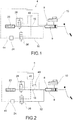
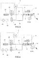
- the reference number 4 globally indicates a braking system for vehicles.
- vehicles means both cars and motorcycles.
- the braking system 4 for vehicles comprises a pilot pump 8 provided with a manual actuation means 12, lever and/or pedal.
- the pilot pump 8 comprises a float that is put in motion by the mechanical action of the user on the manual actuation means 12, whether lever or pedal.
- the float 9 has the function of pressurising a brake fluid in a known manner.
- the brake fluid is in turn contained in a tank 10 fluidically connected to the pilot pump 8, in a known manner.
- the pilot pump 8 is fluidically connected, through a first hydraulic conduit 16 containing brake fluid in a known manner, to a sorbing device 20 that simulates the actuation resistance offered by a hydraulically operated braking device 24.
- the sorbing device 20 serves to provide resistance to the actuation of the manual actuation means 12 so as to simulate the normal resistance that a user would have on the manual actuation means 12 following braking action with the braking device 24.
- the sorbing device 20 is typically a mechanical device equipped with springs and similar devices for simulating the resistance provided by normal devices.
- the braking device 24 can be of various type, comprising for example a disc, drum or shoe brake.
- This invention also applies to braking systems 4 comprising electromechanically operated braking devices 24. Therefore, for the purposes of the scope of protection, the invention also covers braking system 4 solutions comprising said electromechanically operated braking devices 24.
- first shut-off valve 28 Along said first hydraulic conduit 16 is arranged a first shut-off valve 28.
- the first shut-off valve 28 can be opened and closed: in the open configuration, it allows the fluid connection between the pilot pump 8 and the sorbing device 20; in the closed configuration said first shut-off valve 28 disconnects the sorbing device 20 from the pilot pump 8.
- the braking system 4 also comprises a second hydraulic conduit 32 operatively connected to at least one braking device 24 associated to a wheel of said vehicle.
- the second hydraulic conduit 32 is connected to the first hydraulic conduit 16 through a second shut-off valve 36.
- the second shut-off valve 36 can, in turn, be opened and closed; in open conditions, the second shut-off valve 36 allows the fluid connection between the pilot pump 8 and the braking device 24; in this way the user can directly actuate the braking device 24 with a conventional hydraulic actuation by acting on the related manual actuation means 12. In closed condition, the second shut-off valve 36 does not allow the direct fluid connection between the pilot pump 8 and the braking device 24. The user can therefore not directly actuate the braking device 24 by using the manual actuation means 12.
- the braking system 4 comprises a processing and control unit 40 operatively connected to the pilot pump 8, and motor means 44 for the actuation of said at least one braking device 24.
- the motor means 44 are preferably electric motors able to operate, directly or through interposed kinematic mechanisms, said braking devices 24.
- the processing and control unit 40 is advantageously programmed so as to actuate at least one braking device 24 via the motor means 44 as a function of the actuation of the pilot pump 8 through the manual actuation means 12, in a "by-wire" operating condition.
- the first shut-off valve 28 is selectively open and the second shut-off valve 36 is closed.
- “Selectively” means that, in this by-wire operating condition, the first shut-off valve 28 can be open or closed, based on the operating conditions established by the processing and control unit 40, as better described below.
- the processing and control unit 40 is programmed to oversee the operation of the braking system 4 so as to correct the braking action requested by the user via the manual actuation means 12, by actuating the motors means 44 so as to avoid the locking of one or more wheels or the onset of instability of the vehicle during braking.
- the processing and control unit 40 oversees the operation of the braking system 4 with both anti-lock function (ABS) of one or more wheels during a braking action and with the vehicle stability control function, during a braking action.
- ABS anti-lock function
- processing and control unit 40 is programmed to induce on the manual actuation means 12 at least a vibration when it corrects the braking action requested by the user.
- the same processing and control unit 40 induces on the manual actuation means 12 at least a vibration so as to clearly warn the user that an action of instability of the vehicle is occurring due to an excess of braking action in relation to the dynamic conditions of the vehicle and adherence with the ground.
- the processing and control unit 40 is programmed so that, during the correction of the braking action requested by the user, it alternately opens and closes the first shut-off valve 28 so as to create a pressure variation on the manual actuation means 12. In this condition, the second shut-off valve 36 is in closed condition and therefore does not allow the hydraulic connection between the pilot pump 8 and the braking device 24.
- the processing and control unit 40 commands the closing of the first shut-off valve 28: this operation is followed by the generation of a pressure difference in the hydraulic circuit, and in particular in the first hydraulic conduit 16 between upstream and downstream of the first shut-off valve 28, as a result of the pressing of the manual actuation means 12 (either lever or pedal) by the driver.
- the processing and control unit 40 derives the passage of brake fluid in the sorbing device 20 in reduced time intervals. This condition induces a desired vibrational state to the manual actuation means 12, in order to provide feedback to the driver of the vehicle similar to what would occur in the same situation in a vehicle with conventional hydraulic braking system.
- the braking system 4 comprises means for varying the pressure 48 in the first hydraulic conduit 16 operatively connected to the processing and control unit 40 so as to change the pressure in said first hydraulic conduit 16 to induce at least a vibration on the manual actuation means 12, during the correction of the braking action requested by the user.
- the second shut-off valve 36 is in closed condition and therefore does not allow the hydraulic connection between the pilot pump 8 and the braking device 24.
- said means for varying the pressure 48 in the first hydraulic conduit 16 comprise an axial or radial piston pump fluidically connected with said first hydraulic conduit 16. This axial or radial piston pump is able to create a cyclic variation of the pressure in the first hydraulic conduit 16 noticeable on the manual actuation means 12 in the form of vibrations.
- said means of varying the pressure 48 in the first hydraulic conduit 16 comprise a cam-piston system, in which the piston is fluidically connected with said first hydraulic conduit 16 so as to induce a cyclic variation of the pressure in the first hydraulic conduit 16 noticeable on the manual actuation means 12 in the form of vibrations.
- said means of varying the pressure 48 will have to generate a hydraulic pressure capable of overcoming the load at the manual actuation means 12 imposed by the driver.
- the braking system 4 comprises movable mechanical means 52, arranged between the manual actuation means 12 and the pilot pump 8, wherein said movable mechanical means 52 are operatively connected to the processing and control unit 40 that is programmed so as to induce vibrations on the manual actuation means 12 by actuating the movable mechanical means 52, during the correction of the braking action requested by the user.
- the movable mechanical means 52 comprise a rotary electric motor 56 with eccentric mass with respect to a rotation axis of the motor.
- the movable mechanical means 52 comprise an electric motor with related translating mass 60.
- This translating mass 60 will move with a reciprocating rectilinear motion so as to induce the desired vibrations.
- the processing and control unit 40 is programmed to close the first shut-off valve 28 and to actuate the movable mechanical means 52. In this way the pressure variations in the first conduit are obtained exclusively by means of the movable mechanical means 52.
- the processing and control unit 40 is programmed to open the first shut-off valve 28 and to actuate the movable mechanical means 52.
- This open condition of the first shut-off valve 28, and activation of the movable mechanical means 52 achieves, first of all, the return of vibrational feedback to the driver.
- the manual actuation means 12 whether pedal or lever, progressively "sinks", reducing the useful travel of the manual actuation means themselves.
- the processing and control unit 40 is programmed to alternately open and close the first shut-off valve 36 and to actuate the movable mechanical means 52.
- This alternating opening/closing condition of the first shut-off valve 28, and activation of the movable mechanical means 52 achieves, returns a vibrational feedback to the manual actuation means 12.
- the processing and control unit 40 is programmed so that, in a power failure condition in which the motor means 44 malfunction, for the actuation of said at least one braking device 24, it commands the closing of the first shut-off valve 28 and the opening the second shut-off valve 36 so as to allow the direct hydraulic actuation of the braking devices 24 by means of the pilot pump 8.
- the braking system for vehicles according to the invention allows overcoming the drawbacks presented in the prior art.
- the system according to the proposed invention allows returning to the driver a feeling at the pedal or lever of the dynamic state of the vehicle, when they are in the anti-locking function (ABS) or stability control in braking (DSC), or in a situation at the limit of road grip.
- ABS anti-locking function
- DSC stability control in braking
- the advantage of such a solution is to provide the driver a feeling at the pedal or lever similar to that returned by a conventional hydraulic braking system equipped with ABS and/or DSC (Dynamic Stability Control), so as to signal to the driver a state of potential danger to driving and unfaithful response of the vehicle to the commands of the driver.
- ABS and/or DSC Dynamic Stability Control
- the system according to this invention is able to warn the driver of its braking correction intervention: in this way, the driver receives feedback through the manual actuation means, whether lever or pedal, and can for example take notice of the incorrectness of his manner of driving modes and modify it accordingly.
- this feedback consists of a reaction to manual control that not only opposes the intensification of the braking action but also tends to reduce it by returning the manual control to a position of lesser braking request.
- the system also acts promptly and in a repeatable and reliable manner.
- the braking system of this invention has a relatively low cost and adds very limited, and therefore acceptable weight to the vehicle compared to the conventional brake-by-wire solutions of the prior art.
Landscapes
- Engineering & Computer Science (AREA)
- Transportation (AREA)
- Mechanical Engineering (AREA)
- Physics & Mathematics (AREA)
- Fluid Mechanics (AREA)
- Regulating Braking Force (AREA)
Claims (5)
- Système de freinage pour véhicules (4) comprenant- une pompe pilote (8) équipée d'un moyen d'actionnement manuel (12), d'un levier et/ou d'une pédale, qui est connectée de manière fluidique, par l'intermédiaire d'un premier conduit hydraulique (16), à un dispositif sorbant (20) qui simule la résistance d'actionnement offerte par un dispositif de freinage à actionnement hydraulique (24), une première soupape d'arrêt (28) étant agencée le long dudit premier conduit hydraulique (16),- un second conduit hydraulique (32) connecté de manière opérationnelle à au moins un dispositif de freinage (24) associé à une roue dudit véhicule, ledit second conduit hydraulique (32) étant connecté au premier conduit hydraulique (16) par l'intermédiaire d'une seconde soupape d'arrêt (36),- le système (4) comprenant une unité de traitement et de commande (40) connectée de manière opérationnelle à la pompe pilote (8) et des moyens moteurs (44) pour actionner ledit dispositif de freinage (24), au moins au nombre de un, l'unité de traitement et de commande (40) étant programmée de manière à actionner le dispositif de freinage (24) par l'intermédiaire des moyens moteurs (44) en fonction de l'actionnement de la pompe pilote (8) par l'intermédiaire du moyen d'actionnement manuel (12), dans des conditions de fonctionnement « à commande électrique »,- dans lesdites conditions de fonctionnement « à commande électrique », la première soupape d'arrêt (28) étant ouverte de manière sélective et la seconde soupape d'arrêt (36) étant fermée,caractérisé en ce que
l'unité de traitement et de commande (40) est programmée pour superviser le fonctionnement du système de freinage (4) de manière à corriger l'action de freinage demandée par l'utilisateur par l'intermédiaire du moyen d'actionnement manuel (12), par l'actionnement des moyens moteurs (44) de manière à empêcher le verrouillage d'une ou plusieurs roues ou l'apparition d'une instabilité du véhicule pendant le freinage,
ladite unité de traitement et de commande (40) étant programmée pour induire sur le moyen d'actionnement manuel (12) au moins une vibration lorsqu'elle corrige l'action de freinage demandée par l'utilisateur,
où l'unité de traitement et de commande (40) est programmée de façon telle que, pendant la correction de l'action de freinage demandée par l'utilisateur, elle ouvre et ferme de manière alternée la première soupape d'arrêt (28) de manière à créer une variation de pression sur le moyen d'actionnement manuel (12), le système (4) comprenant des moyens pour faire varier la pression (48) dans le premier conduit hydraulique (16) connecté de manière opérationnelle à l'unité de traitement et de commande (40) de manière à modifier la pression dans ledit premier conduit hydraulique (16) pour induire au moins une vibration sur le moyen d'actionnement manuel (12), pendant la correction de l'action de freinage demandée par l'utilisateur,
lesdits moyens pour faire varier la pression (48) dans le premier conduit hydraulique (16) comprenant une pompe à piston axial ou radial connectée de manière fluidique audit premier conduit hydraulique (16). - Système de freinage pour véhicules (4) comprenant- une pompe pilote (8) équipée d'un moyen d'actionnement manuel (12), d'un levier et/ou d'une pédale, qui est connectée de manière fluidique, par l'intermédiaire d'un premier conduit hydraulique (16), à un dispositif sorbant (20) qui simule la résistance d'actionnement offerte par un dispositif de freinage à actionnement hydraulique (24), une première soupape d'arrêt (28) étant agencée le long dudit premier conduit hydraulique (16),- un second conduit hydraulique (32) connecté de manière opérationnelle à au moins un dispositif de freinage (24) associé à une roue dudit véhicule, ledit second conduit hydraulique (32) étant connecté au premier conduit hydraulique (16) par l'intermédiaire d'une seconde soupape d'arrêt (36),- le système (4) comprenant une unité de traitement et de commande (40) connectée de manière opérationnelle à la pompe pilote (8) et des moyens moteurs (44) pour actionner ledit dispositif de freinage (24), au moins au nombre de un, l'unité de traitement et de commande (40) étant programmée de manière à actionner le dispositif de freinage (24) par l'intermédiaire des moyens moteurs (44) en fonction de l'actionnement de la pompe pilote (8) par l'intermédiaire du moyen d'actionnement manuel (12), dans des conditions de fonctionnement « à commande électrique »,- dans lesdites conditions de fonctionnement « à commande électrique », la première soupape d'arrêt (28) étant ouverte de manière sélective et la seconde soupape d'arrêt (36) étant fermée,caractérisé en ce que
l'unité de traitement et de commande (40) est programmée pour superviser le fonctionnement du système de freinage (4) de manière à corriger l'action de freinage demandée par l'utilisateur par l'intermédiaire du moyen d'actionnement manuel (12), par l'actionnement des moyens moteurs (44) de manière à empêcher le verrouillage d'une ou plusieurs roues ou l'apparition d'une instabilité du véhicule pendant le freinage,
ladite unité de traitement et de commande (40) étant programmée pour induire sur le moyen d'actionnement manuel (12) au moins une vibration lorsqu'elle corrige l'action de freinage demandée par l'utilisateur,
où l'unité de traitement et de commande (40) est programmée de façon telle que, pendant la correction de l'action de freinage demandée par l'utilisateur, elle ouvre et ferme de manière alternée la première soupape d'arrêt (28) de manière à créer une variation de pression sur le moyen d'actionnement manuel (12), le système (4) comprenant des moyens pour faire varier la pression (48) dans le premier conduit hydraulique (16) connecté de manière opérationnelle à l'unité de traitement et de commande (40) de manière à modifier la pression dans ledit premier conduit hydraulique (16) pour induire au moins une vibration sur le moyen d'actionnement manuel (12), pendant la correction de l'action de freinage demandée par l'utilisateur,
lesdits moyens pour faire varier la pression (48) dans le premier conduit hydraulique (16) comprenant un système de came-piston, le piston étant connecté de manière fluidique audit premier conduit hydraulique (16). - Système de freinage pour véhicules (4) selon l'une quelconque des revendications précédentes, dans lequel lesdits dispositifs de freinage (24) comprennent un frein à disques, à tambour ou à mâchoires.
- Système de freinage pour véhicules (4) selon l'une quelconque des revendications précédentes, dans lequel l'unité de traitement et de commande (40) est programmée de façon telle que, dans des conditions de panne d'alimentation dans lesquelles les moyens moteurs (44) sont défaillants, pour l'actionnement dudit dispositif de freinage (24), au moins au nombre de un, elle commande la fermeture de la première soupape d'arrêt (28) et l'ouverture de la seconde soupape d'arrêt (36) de manière à permettre l'actionnement hydraulique direct des dispositifs de freinage (24) au moyen de la pompe pilote (8).
- Procédé d'actionnement et de commande d'un système de freinage (4), comprenant l'étape de commande du fonctionnement d'un système de freinage pour véhicules (4) selon l'une quelconque des revendications 1 à 4.
Applications Claiming Priority (2)
| Application Number | Priority Date | Filing Date | Title |
|---|---|---|---|
| ITUB2015A006916A ITUB20156916A1 (it) | 2015-12-09 | 2015-12-09 | Impianto frenante per veicoli di tipo brake by wire munito di simulatore di feedback idraulico, e metodo di attuazione di un impianto frenante per veicoli |
| PCT/IB2016/057411 WO2017098419A1 (fr) | 2015-12-09 | 2016-12-07 | Système de freinage à commande électronique pour des véhicules comportant un simulateur de rétroaction hydraulique et procédé d'actionnement d'un système de freinage pour véhicules associé |
Publications (3)
| Publication Number | Publication Date |
|---|---|
| EP3386812A1 EP3386812A1 (fr) | 2018-10-17 |
| EP3386812B1 true EP3386812B1 (fr) | 2020-09-23 |
| EP3386812B8 EP3386812B8 (fr) | 2021-09-01 |
Family
ID=55538532
Family Applications (1)
| Application Number | Title | Priority Date | Filing Date |
|---|---|---|---|
| EP16828774.6A Active EP3386812B8 (fr) | 2015-12-09 | 2016-12-07 | Brake-by-wire systeme de freinage pour véhucules avec simulation de rétroaction hydraulique, et un tel -procédé |
Country Status (7)
| Country | Link |
|---|---|
| US (1) | US10647308B2 (fr) |
| EP (1) | EP3386812B8 (fr) |
| JP (1) | JP6923521B2 (fr) |
| KR (1) | KR102655172B1 (fr) |
| CN (1) | CN108367738B (fr) |
| IT (1) | ITUB20156916A1 (fr) |
| WO (1) | WO2017098419A1 (fr) |
Families Citing this family (10)
| Publication number | Priority date | Publication date | Assignee | Title |
|---|---|---|---|---|
| IT201700059733A1 (it) * | 2017-05-31 | 2018-12-01 | Freni Brembo Spa | Impianto frenante per veicoli di tipo brake by wire munito di simulatore di feedback idraulico, e metodo di attuazione di un impianto frenante per veicoli |
| DE102017211877A1 (de) * | 2017-07-12 | 2019-01-17 | Robert Bosch Gmbh | Steuervorrichtung und Verfahren zum Betreiben eines hydraulischen Bremssystems eines Fahrzeugs |
| IT201800008055A1 (it) * | 2018-08-10 | 2020-02-10 | Freni Brembo Spa | Metodo e dispositivo per rilevare e fornire informazioni di valutazione di frenata, indicative di un’emissione di particolato dovuta all’uso di un sistema frenante di un veicolo |
| IT201900005254A1 (it) * | 2019-04-05 | 2020-10-05 | Freni Brembo Spa | Impianto frenante per veicoli di tipo brake by wire munito di azionamento elettrico e di back-up elettrico |
| IT201900025336A1 (it) * | 2019-12-23 | 2021-06-23 | Freni Brembo Spa | Un impianto frenante per veicoli con pedale di azionamento collassabile e il relativo metodo di azionamento di un impianto di frenatura in caso di urto |
| EP4079590B1 (fr) * | 2020-01-23 | 2024-07-10 | HL Mando Corporation | Système de frein électronique et son procédé de commande |
| EP4147930B1 (fr) * | 2020-07-21 | 2025-09-17 | Shenzhen Yinwang Intelligent Technologies Co., Ltd. | Dispositif de commande de frein, système de commande de frein et procédé de commande |
| IT202100011621A1 (it) * | 2021-05-06 | 2022-11-06 | Brembo Spa | Impianto frenante di tipo brake-by-wire per motocicli |
| WO2024252318A1 (fr) * | 2023-06-09 | 2024-12-12 | Brembo S.P.A. | Ensemble maître-cylindre de frein et simulateur de pédale, système de freinage, procédé d'actionnement d'un système de freinage |
| KR102688490B1 (ko) | 2023-12-21 | 2024-07-25 | (주)에이치에스팩 | 차량용 버튼식 브레이크장치 |
Family Cites Families (23)
| Publication number | Priority date | Publication date | Assignee | Title |
|---|---|---|---|---|
| JPS628851A (ja) * | 1985-07-05 | 1987-01-16 | Aisin Seiki Co Ltd | 車両用アンチスキツド装置 |
| DE19753786A1 (de) * | 1997-12-04 | 1999-06-10 | Itt Mfg Enterprises Inc | Bremsanlage für Kraftfahrzeuge |
| US6464307B1 (en) * | 1999-11-24 | 2002-10-15 | Sumitomo (Sei) Brake Systems, Inc. | Automotive hydraulic pressure brake system |
| DE10015714A1 (de) * | 2000-03-29 | 2001-10-04 | Bayerische Motoren Werke Ag | Elektromechanische Fahrzeug-Bremsanlage |
| DE10218973A1 (de) * | 2002-04-27 | 2003-11-06 | Continental Teves Ag & Co Ohg | Verfahren zur Steuerung einer hydraulischen Fahrzeugbremsanlage mit aktiver hydraulischer Bremskraftverstärkung und hydraulischer Bremsanlage |
| JP2004090899A (ja) * | 2002-09-04 | 2004-03-25 | Advics:Kk | 車両用ブレーキ警報装置 |
| EP1646543B1 (fr) * | 2003-07-11 | 2007-09-26 | Continental Teves AG & Co. oHG | Systeme de freinage electro-hydraulique pour automobiles |
| DE10346674A1 (de) * | 2003-07-11 | 2005-01-27 | Continental Teves Ag & Co. Ohg | Elektrohydraulische Bremskraftanlage für Kraftfahrzeuge |
| WO2005124500A1 (fr) * | 2004-06-21 | 2005-12-29 | Hitachi, Ltd. | Dispositif d'entr)e d'op)rations |
| JP4506405B2 (ja) * | 2004-10-25 | 2010-07-21 | トヨタ自動車株式会社 | 液圧ブレーキ装置 |
| DE102005012775B4 (de) * | 2005-03-19 | 2016-02-25 | Bayerische Motoren Werke Aktiengesellschaft | Vorrichtung zur Erhöhung der Fahrsicherheit bei einem einspurigen Kraftfahrzeug |
| JP5049939B2 (ja) * | 2008-10-07 | 2012-10-17 | 本田技研工業株式会社 | 車両用ブレーキ装置 |
| DE102008044002A1 (de) * | 2008-11-24 | 2010-05-27 | Robert Bosch Gmbh | Bremssystem für ein Kraftfahrzeug sowie Kraftfahrzeug |
| KR101058614B1 (ko) * | 2008-12-11 | 2011-08-25 | 현대모비스 주식회사 | 회생 제동 액추에이터 장치 |
| DE102013204778B4 (de) * | 2012-03-22 | 2026-03-26 | Aumovio Germany Gmbh | Verfahren zur haptischen Information des Fahrers eines Kraftfahrzeugs |
| DE102012025423A1 (de) * | 2012-12-21 | 2014-06-26 | Lucas Automotive Gmbh | Elektrohydraulische Fahrzeug-Bremsanlage und Verfahren zum Betreiben derselben |
| DE102013209733A1 (de) * | 2013-05-24 | 2014-11-27 | Robert Bosch Gmbh | Hauptbremszylindersystem und Bremssystem für ein Fahrzeug |
| GB2528845B (en) * | 2014-07-30 | 2016-12-14 | Jaguar Land Rover Ltd | Feedback through brake inputs |
| KR102480676B1 (ko) * | 2015-12-04 | 2022-12-23 | 에이치엘만도 주식회사 | 전자식 브레이크 시스템 |
| KR102554822B1 (ko) * | 2016-08-24 | 2023-07-12 | 에이치엘만도 주식회사 | 차량 제어 장치 및 그 제어 방법 |
| DE102016217144A1 (de) * | 2016-09-08 | 2018-03-08 | Audi Ag | Verfahren zur Aufprägung von haptischen Informationsrückmeldungen auf ein Bremspedal |
| US10870418B2 (en) * | 2017-02-15 | 2020-12-22 | Mando Corporation | Electronic brake system and control method thereof |
| US10479335B2 (en) * | 2017-12-22 | 2019-11-19 | Robert Bosch Gmbh | Vehicle braking system with ABS emulation |
-
2015
- 2015-12-09 IT ITUB2015A006916A patent/ITUB20156916A1/it unknown
-
2016
- 2016-12-07 CN CN201680071325.6A patent/CN108367738B/zh active Active
- 2016-12-07 KR KR1020187015579A patent/KR102655172B1/ko active Active
- 2016-12-07 US US15/779,936 patent/US10647308B2/en active Active
- 2016-12-07 JP JP2018525724A patent/JP6923521B2/ja active Active
- 2016-12-07 EP EP16828774.6A patent/EP3386812B8/fr active Active
- 2016-12-07 WO PCT/IB2016/057411 patent/WO2017098419A1/fr not_active Ceased
Non-Patent Citations (1)
| Title |
|---|
| None * |
Also Published As
| Publication number | Publication date |
|---|---|
| CN108367738A (zh) | 2018-08-03 |
| US10647308B2 (en) | 2020-05-12 |
| KR20180091828A (ko) | 2018-08-16 |
| JP6923521B2 (ja) | 2021-08-18 |
| KR102655172B1 (ko) | 2024-04-08 |
| US20190001946A1 (en) | 2019-01-03 |
| WO2017098419A1 (fr) | 2017-06-15 |
| EP3386812A1 (fr) | 2018-10-17 |
| ITUB20156916A1 (it) | 2017-06-09 |
| JP2018538190A (ja) | 2018-12-27 |
| EP3386812B8 (fr) | 2021-09-01 |
| CN108367738B (zh) | 2021-06-25 |
Similar Documents
| Publication | Publication Date | Title |
|---|---|---|
| US10647308B2 (en) | Brake-by-wire braking system for vehicles provided with hydraulic feedback simulator and method of actuating a braking system for vehicles thereof | |
| KR102479868B1 (ko) | 2 개의 압력원들을 가진 제동 시스템 및 2 개의 압력원들을 가진 제동 시스템을 작동하는 방법 | |
| EP3178712B1 (fr) | Système de freinage de type « freinage électronique » pour véhicules pourvu de simulateur hydraulique et procédé d'actionnement | |
| JP6584647B2 (ja) | ブレーキシステム及びブレーキシステムを動作させるための方法 | |
| EP3630559B1 (fr) | Système de freinage pour véhicules à freinage câblé comportant un simulateur de rétroaction hydraulique, et procédé d'actionnement d'un système de freinage pour véhicules | |
| US9845085B2 (en) | Method for providing haptic information for a driver of a motor vehicle, and brake system | |
| JP2018538190A5 (fr) | ||
| EP3000674B1 (fr) | Système de support de frein électronique destiné à être utilisé lorsque le système de frein de service a échoué ou est dégradé | |
| KR102701452B1 (ko) | 자율 주행 육상 차량을 위한 전자 유압식 차량 파워브레이크 시스템 | |
| US20170225664A1 (en) | Feedback through brake inputs | |
| US9096205B2 (en) | Brake system and method for operating same | |
| EP3009314B1 (fr) | Système de freins pour véhicule controlé automatiquement et procédé correspondant d'actuation d'un tel système | |
| JP2018103848A (ja) | ブレーキ装置 | |
| EP3445624B1 (fr) | Système de freinage commandé automatisé pour véhicules | |
| EP3083349B1 (fr) | Système de freinage à commande automatique | |
| KR102074239B1 (ko) | 전동식 제동장치의 제어 방법 |
Legal Events
| Date | Code | Title | Description |
|---|---|---|---|
| STAA | Information on the status of an ep patent application or granted ep patent |
Free format text: STATUS: UNKNOWN |
|
| STAA | Information on the status of an ep patent application or granted ep patent |
Free format text: STATUS: THE INTERNATIONAL PUBLICATION HAS BEEN MADE |
|
| PUAI | Public reference made under article 153(3) epc to a published international application that has entered the european phase |
Free format text: ORIGINAL CODE: 0009012 |
|
| STAA | Information on the status of an ep patent application or granted ep patent |
Free format text: STATUS: REQUEST FOR EXAMINATION WAS MADE |
|
| 17P | Request for examination filed |
Effective date: 20180515 |
|
| AK | Designated contracting states |
Kind code of ref document: A1 Designated state(s): AL AT BE BG CH CY CZ DE DK EE ES FI FR GB GR HR HU IE IS IT LI LT LU LV MC MK MT NL NO PL PT RO RS SE SI SK SM TR |
|
| AX | Request for extension of the european patent |
Extension state: BA ME |
|
| DAV | Request for validation of the european patent (deleted) | ||
| DAX | Request for extension of the european patent (deleted) | ||
| GRAP | Despatch of communication of intention to grant a patent |
Free format text: ORIGINAL CODE: EPIDOSNIGR1 |
|
| STAA | Information on the status of an ep patent application or granted ep patent |
Free format text: STATUS: GRANT OF PATENT IS INTENDED |
|
| INTG | Intention to grant announced |
Effective date: 20200506 |
|
| RIN1 | Information on inventor provided before grant (corrected) |
Inventor name: PAGANI, LUCA Inventor name: UGOLINI, LUCA Inventor name: FORNI, FABRIZIO Inventor name: GALIZZI, VALERIO Inventor name: DOZZI, FRANCESCO Inventor name: SZEWCZYK, BENIAMIN Inventor name: ALEMANNO, FABIO |
|
| GRAS | Grant fee paid |
Free format text: ORIGINAL CODE: EPIDOSNIGR3 |
|
| GRAA | (expected) grant |
Free format text: ORIGINAL CODE: 0009210 |
|
| STAA | Information on the status of an ep patent application or granted ep patent |
Free format text: STATUS: THE PATENT HAS BEEN GRANTED |
|
| AK | Designated contracting states |
Kind code of ref document: B1 Designated state(s): AL AT BE BG CH CY CZ DE DK EE ES FI FR GB GR HR HU IE IS IT LI LT LU LV MC MK MT NL NO PL PT RO RS SE SI SK SM TR |
|
| REG | Reference to a national code |
Ref country code: GB Ref legal event code: FG4D |
|
| REG | Reference to a national code |
Ref country code: CH Ref legal event code: EP |
|
| REG | Reference to a national code |
Ref country code: IE Ref legal event code: FG4D |
|
| REG | Reference to a national code |
Ref country code: AT Ref legal event code: REF Ref document number: 1316093 Country of ref document: AT Kind code of ref document: T Effective date: 20201015 Ref country code: DE Ref legal event code: R096 Ref document number: 602016044677 Country of ref document: DE |
|
| PG25 | Lapsed in a contracting state [announced via postgrant information from national office to epo] |
Ref country code: SE Free format text: LAPSE BECAUSE OF FAILURE TO SUBMIT A TRANSLATION OF THE DESCRIPTION OR TO PAY THE FEE WITHIN THE PRESCRIBED TIME-LIMIT Effective date: 20200923 Ref country code: FI Free format text: LAPSE BECAUSE OF FAILURE TO SUBMIT A TRANSLATION OF THE DESCRIPTION OR TO PAY THE FEE WITHIN THE PRESCRIBED TIME-LIMIT Effective date: 20200923 Ref country code: NO Free format text: LAPSE BECAUSE OF FAILURE TO SUBMIT A TRANSLATION OF THE DESCRIPTION OR TO PAY THE FEE WITHIN THE PRESCRIBED TIME-LIMIT Effective date: 20201223 Ref country code: GR Free format text: LAPSE BECAUSE OF FAILURE TO SUBMIT A TRANSLATION OF THE DESCRIPTION OR TO PAY THE FEE WITHIN THE PRESCRIBED TIME-LIMIT Effective date: 20201224 Ref country code: BG Free format text: LAPSE BECAUSE OF FAILURE TO SUBMIT A TRANSLATION OF THE DESCRIPTION OR TO PAY THE FEE WITHIN THE PRESCRIBED TIME-LIMIT Effective date: 20201223 Ref country code: HR Free format text: LAPSE BECAUSE OF FAILURE TO SUBMIT A TRANSLATION OF THE DESCRIPTION OR TO PAY THE FEE WITHIN THE PRESCRIBED TIME-LIMIT Effective date: 20200923 |
|
| REG | Reference to a national code |
Ref country code: AT Ref legal event code: MK05 Ref document number: 1316093 Country of ref document: AT Kind code of ref document: T Effective date: 20200923 |
|
| PG25 | Lapsed in a contracting state [announced via postgrant information from national office to epo] |
Ref country code: LV Free format text: LAPSE BECAUSE OF FAILURE TO SUBMIT A TRANSLATION OF THE DESCRIPTION OR TO PAY THE FEE WITHIN THE PRESCRIBED TIME-LIMIT Effective date: 20200923 Ref country code: RS Free format text: LAPSE BECAUSE OF FAILURE TO SUBMIT A TRANSLATION OF THE DESCRIPTION OR TO PAY THE FEE WITHIN THE PRESCRIBED TIME-LIMIT Effective date: 20200923 |
|
| REG | Reference to a national code |
Ref country code: NL Ref legal event code: MP Effective date: 20200923 |
|
| REG | Reference to a national code |
Ref country code: LT Ref legal event code: MG4D |
|
| PG25 | Lapsed in a contracting state [announced via postgrant information from national office to epo] |
Ref country code: LT Free format text: LAPSE BECAUSE OF FAILURE TO SUBMIT A TRANSLATION OF THE DESCRIPTION OR TO PAY THE FEE WITHIN THE PRESCRIBED TIME-LIMIT Effective date: 20200923 Ref country code: RO Free format text: LAPSE BECAUSE OF FAILURE TO SUBMIT A TRANSLATION OF THE DESCRIPTION OR TO PAY THE FEE WITHIN THE PRESCRIBED TIME-LIMIT Effective date: 20200923 Ref country code: PT Free format text: LAPSE BECAUSE OF FAILURE TO SUBMIT A TRANSLATION OF THE DESCRIPTION OR TO PAY THE FEE WITHIN THE PRESCRIBED TIME-LIMIT Effective date: 20210125 Ref country code: CZ Free format text: LAPSE BECAUSE OF FAILURE TO SUBMIT A TRANSLATION OF THE DESCRIPTION OR TO PAY THE FEE WITHIN THE PRESCRIBED TIME-LIMIT Effective date: 20200923 Ref country code: EE Free format text: LAPSE BECAUSE OF FAILURE TO SUBMIT A TRANSLATION OF THE DESCRIPTION OR TO PAY THE FEE WITHIN THE PRESCRIBED TIME-LIMIT Effective date: 20200923 Ref country code: SM Free format text: LAPSE BECAUSE OF FAILURE TO SUBMIT A TRANSLATION OF THE DESCRIPTION OR TO PAY THE FEE WITHIN THE PRESCRIBED TIME-LIMIT Effective date: 20200923 |
|
| PG25 | Lapsed in a contracting state [announced via postgrant information from national office to epo] |
Ref country code: AT Free format text: LAPSE BECAUSE OF FAILURE TO SUBMIT A TRANSLATION OF THE DESCRIPTION OR TO PAY THE FEE WITHIN THE PRESCRIBED TIME-LIMIT Effective date: 20200923 Ref country code: AL Free format text: LAPSE BECAUSE OF FAILURE TO SUBMIT A TRANSLATION OF THE DESCRIPTION OR TO PAY THE FEE WITHIN THE PRESCRIBED TIME-LIMIT Effective date: 20200923 Ref country code: ES Free format text: LAPSE BECAUSE OF FAILURE TO SUBMIT A TRANSLATION OF THE DESCRIPTION OR TO PAY THE FEE WITHIN THE PRESCRIBED TIME-LIMIT Effective date: 20200923 Ref country code: PL Free format text: LAPSE BECAUSE OF FAILURE TO SUBMIT A TRANSLATION OF THE DESCRIPTION OR TO PAY THE FEE WITHIN THE PRESCRIBED TIME-LIMIT Effective date: 20200923 Ref country code: IS Free format text: LAPSE BECAUSE OF FAILURE TO SUBMIT A TRANSLATION OF THE DESCRIPTION OR TO PAY THE FEE WITHIN THE PRESCRIBED TIME-LIMIT Effective date: 20210123 |
|
| REG | Reference to a national code |
Ref country code: DE Ref legal event code: R097 Ref document number: 602016044677 Country of ref document: DE |
|
| PG25 | Lapsed in a contracting state [announced via postgrant information from national office to epo] |
Ref country code: SK Free format text: LAPSE BECAUSE OF FAILURE TO SUBMIT A TRANSLATION OF THE DESCRIPTION OR TO PAY THE FEE WITHIN THE PRESCRIBED TIME-LIMIT Effective date: 20200923 |
|
| RAP4 | Party data changed (patent owner data changed or rights of a patent transferred) |
Owner name: BREMBO S.P.A. |
|
| RIN2 | Information on inventor provided after grant (corrected) |
Inventor name: GALIZZI, VALERIO Inventor name: SZEWCZYK, BENIAMIN Inventor name: PAGANI, LUCA Inventor name: FORNI, FABRIZIO Inventor name: UGOLINI, LUCA Inventor name: DOZZI, FRANCESCO Inventor name: ALEMANNO, FABIO |
|
| PLBE | No opposition filed within time limit |
Free format text: ORIGINAL CODE: 0009261 |
|
| REG | Reference to a national code |
Ref country code: CH Ref legal event code: PL Ref country code: CH Ref legal event code: PK Free format text: BERICHTIGUNGEN |
|
| STAA | Information on the status of an ep patent application or granted ep patent |
Free format text: STATUS: NO OPPOSITION FILED WITHIN TIME LIMIT |
|
| REG | Reference to a national code |
Ref country code: CH Ref legal event code: PK Free format text: BERICHTIGUNG B8 |
|
| RAP4 | Party data changed (patent owner data changed or rights of a patent transferred) |
Owner name: BREMBO S.P.A. |
|
| RIN2 | Information on inventor provided after grant (corrected) |
Inventor name: GALIZZI, VALERIO Inventor name: SZEWCZYK, BENIAMIN Inventor name: PAGANI, LUCA Inventor name: FORNI, FABRIZIO Inventor name: UGOLINI, LUCA Inventor name: DOZZI, FRANCESCO Inventor name: ALEMANNO, FABIO |
|
| PG25 | Lapsed in a contracting state [announced via postgrant information from national office to epo] |
Ref country code: SI Free format text: LAPSE BECAUSE OF FAILURE TO SUBMIT A TRANSLATION OF THE DESCRIPTION OR TO PAY THE FEE WITHIN THE PRESCRIBED TIME-LIMIT Effective date: 20200923 Ref country code: DK Free format text: LAPSE BECAUSE OF FAILURE TO SUBMIT A TRANSLATION OF THE DESCRIPTION OR TO PAY THE FEE WITHIN THE PRESCRIBED TIME-LIMIT Effective date: 20200923 Ref country code: MC Free format text: LAPSE BECAUSE OF FAILURE TO SUBMIT A TRANSLATION OF THE DESCRIPTION OR TO PAY THE FEE WITHIN THE PRESCRIBED TIME-LIMIT Effective date: 20200923 |
|
| 26N | No opposition filed |
Effective date: 20210624 |
|
| REG | Reference to a national code |
Ref country code: BE Ref legal event code: MM Effective date: 20201231 |
|
| PG25 | Lapsed in a contracting state [announced via postgrant information from national office to epo] |
Ref country code: LU Free format text: LAPSE BECAUSE OF NON-PAYMENT OF DUE FEES Effective date: 20201207 Ref country code: IE Free format text: LAPSE BECAUSE OF NON-PAYMENT OF DUE FEES Effective date: 20201207 |
|
| PG25 | Lapsed in a contracting state [announced via postgrant information from national office to epo] |
Ref country code: CH Free format text: LAPSE BECAUSE OF NON-PAYMENT OF DUE FEES Effective date: 20201231 Ref country code: LI Free format text: LAPSE BECAUSE OF NON-PAYMENT OF DUE FEES Effective date: 20201231 |
|
| PG25 | Lapsed in a contracting state [announced via postgrant information from national office to epo] |
Ref country code: TR Free format text: LAPSE BECAUSE OF FAILURE TO SUBMIT A TRANSLATION OF THE DESCRIPTION OR TO PAY THE FEE WITHIN THE PRESCRIBED TIME-LIMIT Effective date: 20200923 Ref country code: MT Free format text: LAPSE BECAUSE OF FAILURE TO SUBMIT A TRANSLATION OF THE DESCRIPTION OR TO PAY THE FEE WITHIN THE PRESCRIBED TIME-LIMIT Effective date: 20200923 Ref country code: CY Free format text: LAPSE BECAUSE OF FAILURE TO SUBMIT A TRANSLATION OF THE DESCRIPTION OR TO PAY THE FEE WITHIN THE PRESCRIBED TIME-LIMIT Effective date: 20200923 |
|
| PG25 | Lapsed in a contracting state [announced via postgrant information from national office to epo] |
Ref country code: MK Free format text: LAPSE BECAUSE OF FAILURE TO SUBMIT A TRANSLATION OF THE DESCRIPTION OR TO PAY THE FEE WITHIN THE PRESCRIBED TIME-LIMIT Effective date: 20200923 |
|
| PG25 | Lapsed in a contracting state [announced via postgrant information from national office to epo] |
Ref country code: BE Free format text: LAPSE BECAUSE OF NON-PAYMENT OF DUE FEES Effective date: 20201231 |
|
| REG | Reference to a national code |
Ref country code: DE Ref legal event code: R081 Ref document number: 602016044677 Country of ref document: DE Owner name: BREMBO S.P.A., CURNO, IT Free format text: FORMER OWNER: FRENI BREMBO S.P.A., CURNO, BERGAMO, IT |
|
| PG25 | Lapsed in a contracting state [announced via postgrant information from national office to epo] |
Ref country code: NL Free format text: LAPSE BECAUSE OF NON-PAYMENT OF DUE FEES Effective date: 20200923 |
|
| P01 | Opt-out of the competence of the unified patent court (upc) registered |
Effective date: 20230526 |
|
| PGFP | Annual fee paid to national office [announced via postgrant information from national office to epo] |
Ref country code: GB Payment date: 20251219 Year of fee payment: 10 |
|
| PGFP | Annual fee paid to national office [announced via postgrant information from national office to epo] |
Ref country code: IT Payment date: 20251007 Year of fee payment: 10 |
|
| PGFP | Annual fee paid to national office [announced via postgrant information from national office to epo] |
Ref country code: FR Payment date: 20251128 Year of fee payment: 10 |
|
| PGFP | Annual fee paid to national office [announced via postgrant information from national office to epo] |
Ref country code: DE Payment date: 20251222 Year of fee payment: 10 |