EP3386834B1 - Gepäckablagenmodul zum aufbau einer gepäckablage in einem schienenfahrzeug - Google Patents
Gepäckablagenmodul zum aufbau einer gepäckablage in einem schienenfahrzeug Download PDFInfo
- Publication number
- EP3386834B1 EP3386834B1 EP17701806.6A EP17701806A EP3386834B1 EP 3386834 B1 EP3386834 B1 EP 3386834B1 EP 17701806 A EP17701806 A EP 17701806A EP 3386834 B1 EP3386834 B1 EP 3386834B1
- Authority
- EP
- European Patent Office
- Prior art keywords
- luggage
- rack module
- luggage rack
- module according
- profile
- Prior art date
- Legal status (The legal status is an assumption and is not a legal conclusion. Google has not performed a legal analysis and makes no representation as to the accuracy of the status listed.)
- Active
Links
Images




Classifications
-
- B—PERFORMING OPERATIONS; TRANSPORTING
- B61—RAILWAYS
- B61D—BODY DETAILS OR KINDS OF RAILWAY VEHICLES
- B61D37/00—Other furniture or furnishings
-
- B—PERFORMING OPERATIONS; TRANSPORTING
- B61—RAILWAYS
- B61D—BODY DETAILS OR KINDS OF RAILWAY VEHICLES
- B61D37/00—Other furniture or furnishings
- B61D37/003—Other furniture or furnishings luggage rack and umbrella-stand for rail vehicles
Definitions
- the invention relates to a luggage rack module for assembling a luggage rack in a rail vehicle, the luggage rack module having a support plate which can be fixed by means of at least one holder to a vehicle body shell of the rail vehicle, a rear support profile and a front support rail.
- Such a luggage rack module is, for example, from the DE 10 2007 052 493 A1 known.
- holder modules are provided between two adjacent support modules, which can be connected to both support modules.
- the holder modules are fixed to the shell of a rail vehicle and support the support modules.
- the object of the invention is to create a luggage rack module that enables a visually continuous support surface for luggage and, based on this, promotes an aesthetic impression of the luggage rack from the vehicle interior.
- the luggage rack module has a holder at each of its two ends, which as downward open bracket is formed, the rear support profile is designed for connection to the vehicle body shell and the support plate extends over an entire length of the luggage rack module and is held in receiving grooves of the holder, the rear support profile and the front support beam.
- the design of the holders provided on both sides of the luggage rack module as brackets which are open at the bottom makes it possible to design the bearing surface for luggage along a plurality of luggage rack modules which form a luggage rack and are optically uniform and continuous.
- the support surface is provided, for example, by a support plate, which can also be a glass plate, which is fixed with the aid of the holder, the rear support profile and the front support spar.
- the creation of a continuous support surface also opens up the possibility of designing the luggage rack module uniformly from the bottom.
- the front support beam can have an elongated, groove-shaped recess along its front side for receiving an installation module.
- This installation module can be a seat reservation indicator, a lighting device, a blind field or a handle bar. Since the groove-shaped recess of the front spar extends over its entire length, a uniform appearance of the luggage rack composed of several luggage rack modules is also seen from the side of the luggage rack.
- the elongated, groove-shaped recess on the front of the front spar can also be viewed as a multi-purpose interface, so that only the appearance of the front of the front spar can be changed while retaining other components of the luggage rack module, such as side holders or rear support profile.
- the front support beam can carry a functional element on its rear side assigned to the storage plate.
- a functional element can be, for example, a light band, an arrangement of reading lights and / or a passenger information device. It is also conceivable that a passenger information device fastened to the front support bar is attached with its opposite side to the rear support profile. In this way, the passenger information device is reliably held.
- the rear support profile can be hooked into adapter profiles in its upper region and fixed in the adapter profiles in its lower region, the adapter profiles being fastened to the vehicle body-in-white. Seen from a flow of force, forces exerted by pieces of luggage are thus introduced into the rear support profile via the side holders of the luggage rack module. The forces acting on the support profile are then introduced into the vehicle body shell via the adapter profiles, two of which can be provided, for example, along a luggage rack module. It should be emphasized that the rear support profile can have a hook-shaped section over its entire length, so that the support profile can be moved in the longitudinal direction of the rail vehicle.
- the adapter profiles are connected in their lower region to C-rails of the vehicle body shell, which can extend over essentially an entire length of the vehicle body shell.
- the holders of the luggage rack module can have receiving grooves on their front side, which are arranged in such a way that laterally projecting tabs of the front support bar can be inserted into this receiving groove.
- the support bars could be screwed on both sides from the front via the respective "tab". The screw connection is then through later upstream functional elements covered.
- One-sided insertion and one-sided screwing on the opposite side would also be conceivable.
- the rear support profile can carry a functional element on its front side assigned to the storage plate.
- This functional element can be designed as a light band, as an arrangement of reading lights and / or as a passenger information device.
- the front support bar and the rear support profile can in turn interact to secure the passenger information device.
- the front support beam or the rear support profile can be used to accommodate a power supply for light sources and / or the passenger information device.
- the luggage rack module or the luggage rack composed of several similar luggage rack modules is to be integrated in the side wall area of a rail vehicle, in particular the rear support profile and the adapter profiles can be covered or at least flush with the side wall area.
- the rear support profile has pockets or grooves accessible from below or above for inserting lateral haunch elements.
- a trim panel is attached to the underside of the support plate, which is attached to the front support bar and / or the rear support profile.
- This can be a releasable fastening, for example with the aid of magnetically acting holders, or also clip connections that can be secured by split pins.
- the holders, the front support bar and the rear support profile are detachably connected to one another.
- connection principle is similar at the front and rear.
- bolts which protrude laterally from the rear support profile 33 and are inserted into the cutouts in the extruded profile of the holder 4 in the rear section and screwed from behind (and thus not visible to the passenger).
- the profile pocket that rests on the adapter profile 28.
- the Figures 1 and 2 show a luggage rack section constructed from three luggage rack modules 1 in a first embodiment, which can be mounted, for example, on a side wall of a rail vehicle. For reasons of clarity, only the frontmost luggage rack module 1 is provided with reference numerals in the figures.
- the luggage rack module 1 has a centrally arranged support plate 2, here made of glass.
- the support plate 2 is mounted on its short sides in the receiving grooves 3 of a respective holder 4.
- the holders 4 are each designed as a downwardly open bracket, the receiving grooves 3 being arranged in the lower region of the holders 4 and in the longitudinal direction of the support plate 2, so that adjoining support plates 2 of a plurality of luggage rack modules 1 arranged next to one another can form a continuous support surface as a whole.
- the two end holders 4 are connected to one another in the front area of the luggage rack module 1 by means of a front support bar 5.
- the front support bar 5 shows on its side facing the support plate 2 a receiving groove 6 extending over its entire length, into which the associated edge of the support plate 2 can be inserted.
- the front spar 5 is also equipped with protruding tabs 7 on the end. These tabs 7 engage in receiving grooves 14 provided on the front side in the lower region of the holders 4, so that the front spar 5 connects the front sides of the holders 4 to one another, namely by screwing from the front - as previously explained.
- the screws are concealed by the built-in modules.
- the front support beam 5 has an elongated, groove-shaped recess 8 over its entire length on its front side, in which installation modules of different types can be used.
- a seat reservation indicator is provided for the front of the front support rail 7, which has a rear housing section 9, which is inserted directly into the recess 8 of the front rail 5, the housing section 9 with the technical equipment is also screwed from the front, either only in the area of the holder and or only in the area of the support bars.
- the cover of the seat reservation indicators is clipped in and fixed. From the front, the passenger information device is closed by a strip-shaped display screen 10.
- An insert profile 11 is inserted into the front receiving groove 14 of each holder 4 in order to create a substantially constant end face both in the region of the holder 4 and in the region of the display screen 10.
- the platen 2 is partially covered from below.
- two elongated cladding elements 12, 13 are used in the present exemplary embodiment, the front cladding element 12 being placed against the front support beam 5 from below and being magnetically connected to it, for example.
- the rear cladding element 13 is placed under the rear edge of the support plate and is also magnetically attached to an underside of a rear support profile 33 explained later. (Could also be clipped or connected to the glass plate in a suitable way ... eg via detachably glued Velcro fasteners on the edge of the glass surface and on the cladding elements 12).
- the cladding is formed by an upper cladding element 15 and a lower cladding element 16 which are attached to the rear support profile 33, for example in suitably designed grooves or pockets.
- the cladding elements 15, 16 extend along a respective luggage rack module, namely between the holders 4.
- the receptacle 8 of the front support beam 5 carries a blind profile 17.
- the support plate 2 is not provided with cladding elements on its underside, so that when a luggage rack 18 is shown after the execution in Figure 3 results in a visually appealing, continuous surface.
- Figure 4 shows a luggage rack section with a luggage rack module 19, which likewise does not provide any trim elements on the underside of the storage plate 2. Again, a modification is provided in the area of the front spar 5.
- the elongated receptacle 8 on the front of the front support bar 5 is used in this embodiment to attach a handle bar 20.
- a luggage rack module 21 after Figure 5 is characterized in that a cladding element 22 is placed against the support plate 2 from below, which is fastened both to the rear support profile 33 and to the front support beam 5.
- the cladding element 22 only leaves a generally elliptically shaped central region of the support plate 2 free. Special optical effects are achieved in that the glass of the support plate 2 is illuminated. The lighting is on the side, in the same place where the front reading lights can be attached. The required ambient light is led laterally into the glass plates via LED strips.
- the appearance is such that the cladding surfaces are not interrupted by the holders 4. Especially if split front and rear cladding elements are used (see Figure 1 ) this is relevant. In this case, both cladding elements, including the glass surface in between, run continuously without interruption.
- 5 loudspeakers 25 are accommodated on a rear side 24 of the carrying bar, of which in FIG Figure 6 only one is shown.
- the speakers 25 are fixed in a suitable manner.
- a light band could also be provided instead.
- a passenger information display device 30 is provided in an area below the support plate 2, which extends in the transverse direction of the luggage rack module 29, in the present exemplary embodiment below the holder 4, at least over the entire width of the support plate 2 with fixation in the recesses on the rear and on the front spar or at the same position on the recesses in the holders 4.
- a lower edge of the display device 30 terminates with a lower edge of the cladding element 16.
- FIG Figure 8 the connection of all the different embodiments of luggage rack modules described above is shown in more detail.
- the holder 4 is not only as shown in FIG Figure 6 explained, connected in the rear upper region via the hook-shaped section 26 of the holder 4 and the web-shaped section 27 of the adapter profile 28, but additionally in the rear lower region of the holder 4.
- the adapter profile points towards the rear of the lower region of the holder 4 directed, C-shaped profile area 29, which can be used to connect the holder 4.
- the back of the adapter profile 28 is in turn attached to a side wall section 31, which is part of the vehicle bodyshell. This is done via two C-rails 32 running in the longitudinal direction of the vehicle tube construction, the end faces of which each abut a rear side of the adapter profile 28 in such a way that that a suitable screw connection is made possible using slot nuts.
- the luggage rack module 23 which here represents all of the above-described embodiments for luggage rack modules with regard to the attachment to the side wall section 31, can be attached to the side wall section 31 via two adapter profiles 28.
- the rear support profile 33 extends between the holders 4 and also has in its lower region a receiving groove 34 which extends over the entire length of the rear support profile 33 and which serves for the rear mounting of the support plate 2.
- the holders 4 also have receiving grooves 35 in their rear, lower region, which are aligned with the receiving groove 33.
- the holders adjoining the holders 4 provided with reference numerals on the outside belong to respectively adjacent luggage rack modules. These holders are only on the side of the holders 4, so that there is no force-transmitting connection between adjacent luggage rack modules.
- Figure 10 now shows a view of the luggage rack module 23 from behind.
- the cross section of the rear support profile 33 corresponds to the corresponding cross section of the holder 4.
- the hook-shaped section 26 extends in the upper rear region over an entire length of the luggage rack module 23, namely from the outer end of one holder 4 via the rear support profile 33 to the outer end of the opposite other holder 4. Since the luggage rack module 23 is thus free Compared to the two adapter profiles 28 in the present exemplary embodiment, luggage rack modules adjoining one another in the longitudinal direction of the rail vehicle can be aligned with one another in a simple manner.
Landscapes
- Engineering & Computer Science (AREA)
- Mechanical Engineering (AREA)
- Vehicle Step Arrangements And Article Storage (AREA)
- Fittings On The Vehicle Exterior For Carrying Loads, And Devices For Holding Or Mounting Articles (AREA)
Description
- Die Erfindung bezieht sich auf ein Gepäckablagenmodul zum Aufbau einer Gepäckablage in einem Schienenfahrzeug, wobei das Gepäckablagenmodul eine Auflageplatte, die mittels wenigstens einem Halter gegenüber einem Fahrzeugrohbau des Schienenfahrzeugs fixierbar ist, ein rückwärtiges Tragprofil und einen vorderen Tragholm aufweist.
- Ein solches Gepäckablagenmodul ist beispielsweise aus der
DE 10 2007 052 493 A1 bekannt. Bei dem dort vorgestellten Gepäckablagenmodul sind zwischen zwei benachbarten Auflagemodulen Haltermodule vorgesehen, die mit beiden Auflagemodulen verbindbar sind. Die Haltermodule sind an einem Rohbau eines Schienenfahrzeugs fixiert und tragen die Auflagemodule. - Bei einem solchen Gepäckablagenmodul für Schienenfahrzeuge wird es als nachteilig angesehen, dass eine Gepäckablage hinsichtlich ihrer Auflagefläche nicht durchgehend ausgeführt werden kann. Dem steht entgegen, dass die erforderlichen Haltemodule jeweils zwischen zwei benachbarten Auflagemodulen angeordnet sind und somit zwingend die Auflagefläche unterbrechen. Dies hat insbesondere auch insofern Auswirkungen, dass bei einer Betrachtung einer Gepäckablage von unten ein ästhetisch uneinheitliches Bild entsteht.
- Ausgehend hiervon liegt der Erfindung die Aufgabe zugrunde, ein Gepäckablagenmodul zu schaffen, das eine optisch durchgehende Auflagefläche für Gepäck ermöglicht und, davon ausgehend, einen ästhetischen Eindruck der Gepäckablage vom Fahrzeuginnenraum aus fördert.
- Diese Aufgabe wird bei dem Gepäckablagenmodul der eingangs genannten Art dadurch gelöst, dass das Gepäckablagenmodul an seinen beiden Enden jeweils einen Halter aufweist, der als nach unten offener Bügel ausgebildet ist, wobei das rückwärtige Tragprofil zur Anbindung an den Fahrzeugrohbau ausgebildet ist und sich die Auflageplatte über eine gesamte Länge des Gepäckablagenmoduls erstreckt sowie in Aufnahmenuten der Halter, des rückwärtigen Tragprofils und des vorderen Tragholms gehalten ist.
- Durch die Ausbildung der beidseitig des Gepäckablagenmoduls vorgesehenen Halter als nach unten offene Bügel wird es ermöglicht, die Auflagefläche für Gepäck entlang mehrerer, eine Gepäckablage aufbauender Gepäckablagenmodule optisch einheitlich und durchgehend zu gestalten. Die Auflagefläche wird beispielsweise durch eine Auflageplatte bereitgestellt, bei der es sich auch um eine Glasplatte handeln kann, die mithilfe der Halter, des rückwärtigen Tragprofils und des vorderen Tragholms fixiert ist. Mit der Schaffung einer durchgehenden Auflagefläche eröffnet sich zudem die Möglichkeit, das Gepäckablagenmodul von seiner Unterseite her einheitlich zu gestalten.
- Der vordere Tragholm kann entlang seiner Vorderseite eine langegestreckte, nutförmige Ausnehmung zur Aufnahme eines Einbaumoduls aufweisen. Bei diesem Einbaumodul kann es sich um eine Sitzplatzreservierungsanzeige, eine Beleuchtungsvorrichtung, ein Blindfeld oder einen Griffholm handeln. Da sich die nutförmige Ausnehmung des vorderen Tragholms über dessen gesamte Länge erstreckt, wird in dieser Weise auch von der Seite der Gepäckablage gesehen, ein einheitliches Erscheinungsbild der aus mehreren Gepäckablagenmodulen zusammengesetzten Gepäckablage, geschaffen.
- Die langgestreckte, nutförmige Ausnehmung an der Vorderseite des vorderen Tragholms kann zudem als Mehrzweckschnittstelle angesehen werden, so dass bei Beibehaltung weiterer Komponenten des Gepäckablagenmoduls, wie seitliche Halter oder rückwärtiges Tragprofil, ausschließlich das Erscheinungsbild der Vorderseite des vorderen Tragholms änderbar ist.
- Der vordere Tragholm kann an seiner der Ablageplatte zugeordneten hinteren Seite ein Funktionselement tragen. Bei einem solchen Funktionselement kann es sich beispielsweise um ein Lichtband, eine Anordnung von Leseleuchten und/oder eine Fahrgastinformationsvorrichtung handeln. Auch ist es denkbar, dass eine an dem vorderen Tragholm befestigte Fahrgastinformationsvorrichtung mit ihrer gegenüberliegenden Seite an dem rückwärtigen Tragprofil angebracht ist. Auf diese Weise ergibt sich eine zuverlässige Halterung der Fahrgastinformationsvorrichtung.
- Das rückwärtige Tragprofil kann in seinem oberen Bereich in Adapterprofile eingehakt und in seinem unteren Bereich in den Adapterprofilen fixiert sein, wobei die Adapterprofile am Fahrzeugrohbau befestigt sind. Von einem Kraftfluss her gesehen, werden somit von Gepäckstücken ausgeübte Kräfte über die seitlichen Halter des Gepäckablagenmoduls in das rückwärtige Tragprofil eingeleitet. Die auf das Tragprofil einwirkenden Kräfte werden dann über die Adapterprofile, von denen beispielsweise entlang eines Gepäckablagenmoduls zwei Stück vorgesehen sein können, in den Fahrzeugrohbau eingeleitet. Es ist hervorzuheben, dass das rückwärtige Tragprofil über seine gesamte Länge einen hakenförmigen Abschnitt aufweisen kann, so dass eine Verschieblichkeit des Tragprofils in Längsrichtung des Schienenfahrzeugs ermöglicht ist. In einer Ausführungsform sind die Adapterprofile in ihrem unteren Bereich an C-Schienen des Fahrzeugrohbaus angebunden, die sich über im Wesentlichen eine gesamte Länge des Fahrzeugrohbaus erstrecken können.
- Die Halter des Gepäckablagenmoduls können an ihrer Vorderseite Aufnahmenuten aufweisen, die derart angeordnet sind, dass seitlich vorstehende Laschen des vorderen Tragholms in diese Aufnahmenut einsetzbar sind. In dieser Weise wird eine geeignete Befestigung der vorderen Tragholme an zugehörigen Haltern eines Gepäckablagenmoduls ermöglicht. Die Tragholme könnten u.a. beidseitig über die jeweilige "Lasche" von vorne verschraubt werden. Die Verschraubung wird dann später durch vorgelagerte Funktionselemente abgedeckt. Es wäre auch ein einseitiges Einstecken und einseitiges Verschrauben an der gegenüberliegenden Seite denkbar.
- Das rückwärtige Tragprofil kann an seiner der Ablageplatte zugeordneten vorderen Seite ein Funktionselement tragen. Dieses Funktionselement kann als Lichtband, als eine Anordnung von Leseleuchten und/oder als Fahrgastinformationsvorrichtung ausgebildet sein. Im Hinblick auf die Einbindung einer Fahrgastinformationsvorrichtung in das Gepäckablagenmodul kann wiederum ein Zusammenwirken des vorderen Tragholms und des rückwärtigen Tragprofils zur Befestigung der Fahrgastinformationsvorrichtung zum Tragen kommen. Zudem ist es möglich, dass der vordere Tragholm oder das rückwärtige Tragprofil zur Unterbringung einer Stromversorgung für Lichtquellen und/oder die Fahrgastinformationsvorrichtung genutzt werden.
- Das Gepäckablagenmodul oder die aus mehreren gleichartigen Gepäckablagenmodulen zusammengesetzte Gepäckablage ist im Seitenwandbereich eines Schienenfahrzeug zu integrieren, wobei insbesondere das rückwärtige Tragprofil und die Adapterprofile verdeckt sein können oder zumindest flächenbündig mit dem Seitenwandbereich abschließen. Zu diesem Zweck kann es vorgesehen sein, dass das rückwärtige Tragprofil von unten oder oben zugängliche Taschen oder Nuten zum Einstecken seitlicher Voutenelemente aufweist.
- Zum aufwandsarmen Modifizieren des optischen Eindrucks der Unterseite des Gepäckablagenmoduls kann vorgesehen sein, dass gegen die Unterseite der Auflageplatte eine Verkleidungsblende gesetzt ist, die an dem vorderen Tragholm und/oder dem rückwärtigen Tragprofil befestigt ist. Dabei kann es sich um eine lösbare Befestigung beispielsweise mithilfe magnetisch wirkender Halter oder auch um Clipsverbindungen, die durch Splinte gesichert sein können, handeln. Die Variationsmöglichkeit besteht nun darin, die Verkleidungsblende in verschiedener Art auszuführen, wobei wiederum die übrige Ausführung des Gepäckablagenmoduls ungeändert bleibt.
- Zur einfachen Demontage des Gepäckablagenmoduls kann vorgesehen sein, dass die Halter, der vordere Tragholm und das rückwärtige Tragprofil untereinander lösbar verbunden sind.
- Das Verbindungsprinzip ist vorne wie hinten ähnlich. Auch hier gibt es Bolzen, die am rückwärtigen Tragprofil 33 seitlich herausragen und in die Aussparungen des Strangpressprofiles des Halters 4 im hinteren Abschnitt eingesteckt und von hinten (und damit für den Fahrgast nicht sichtbar) verschraubt werden.
(z.B. oberhalb der Nut 35 die Profiltasche, die am Adapterprofil 28 anliegt). - Ausführungsbeispiele der Erfindung werden nachfolgend unter Bezugnahme auf die Zeichnungen noch näher beschrieben. Es zeigen:
- Figur 1
- eine perspektivische, auseinandergezogene Ansicht eines aus drei Gepäckablagenmodulen in einer ersten Ausführungsform zusammengesetzen Gepäckablagenabschnitts,
- Figur 2
- eine perspektivische Ansicht des Gepäckablagenabschnitts von
Figur 1 in zusammengesetztem Zustand, - Figur 3
- eine perspektivische Ansicht eines aus drei Gepäckablagenmodulen in einer zweiten Ausführungsform zusammengesetzen Gepäckablagenabschnitts,
- Figur 4
- eine perspektivische Ansicht eines aus drei Gepäckablagenmodulen in einer dritten Ausführungsform zusammengesetzen Gepäckablagenabschnitts,
- Figur 5
- eine perspektivische Ansicht eines aus drei Gepäckablagenmodulen in einer vierten Ausführungsform zusammengesetzten Gepäckablagenabschnitts,
- Figur 6
- eine perspektivische Ansicht von der Seite auf ein Gepäckablagenmodul in einer fünften Ausführungsform in Zusammensicht mit einem angrenzenden Seitenwandabschnitt eines Schienenfahrzeugs,
- Figur 7
- eine perspektivische Ansicht eines aus drei Gepäckablagenmodulen in einer sechsten Ausführungsform zusammengesetzen Gepäckablagenabschnitts,
- Figur 8
- eine Querschnittsansicht eines Gepäckablagenmoduls zum Aufbau des Gepäckablagenabschnitts nach
Figur 4 , - Figur 9
- eine perspektivische Ansicht eines Gepäckablagenmoduls und
- Figur 10
- eine weitere perspektivische Ansicht des Gepäckablagenmoduls von
Figur 9 . - Die
Figuren 1 und2 zeigen einen aus drei Gepäckablagenmodulen 1 in einer ersten Ausführungsform aufgebauten Gepäckablagenabschnitt, der beispielsweise an einer Seitenwand eines Schienenfahrzeugs montierbar ist. Aus Gründen der Übersichtlichkeit ist in den Figuren ausschließlich das jeweils vorderste Gepäckablagenmodul 1 mit Bezugszeichen versehen. - Das Gepäckablagenmodul 1 weist eine zentral angeordnete Auflageplatte 2, hier aus Glas, auf. Die Auflageplatte 2 ist an ihren kurzen Seiten jeweils in Aufnahmenuten 3 eines jeweiligen Halters 4 gelagert. Die Halter 4 sind jeweils als nach unten offene Bügel ausgebildet, wobei die Aufnahmenuten 3 im unteren Bereich der Halter 4 und in Längsrichtung der Auflageplatte 2 angeordnet sind, so dass aneinander anschließende Auflageplatten 2 mehrerer nebeneinander angeordneter Gepäckablagenmodule 1 insgesamt eine durchgehende Auflagefläche ausbilden können.
- Die beiden endseitigen Halter 4 sind im vorderen Bereich des Gepäckablagenmoduls 1 über einen vorderen Tragholm 5 miteinander verbunden. Der vordere Tragholm 5 zeigt auf seiner der Auflageplatte 2 zugewandten Seite eine sich über ihre ganze Länge erstreckende Aufnahmenut 6, in welche der zugeordnete Rand der Auflageplatte 2 einschiebbar ist. Der vordere Holm 5 ist zudem mit endseitigen, vorstehenden Laschen 7 ausgestattet. Diese Laschen 7 greifen in an der Vorderseite im unteren Bereich der Halter 4 vorgesehene Aufnahmenuten 14 ein, so dass der vordere Holm 5 die Vorderseiten der Halter 4 miteinander verbindet, und zwar durch Verschrauben von vorne - wie vorhin erläutert. Die Schrauben werden durch die Einbaumodule kaschiert.
- Der vordere Tragholm 5 weist über seine gesamte Länge an seiner Vorderseite eine langgestreckte, nutförmige Ausnehmung 8 auf, in welche Einbaumodule verschiedener Art einsetzbar sind. Im Ausführungsbeispiel der
Figur 1 ist für die Vorderseite des vorderen Tragholms 7 eine Sitzreservierungsanzeige vorgesehen, die einen hinteren Gehäuseabschnitt 9 aufweist, der unmittelbar in die Ausnehmung 8 des vorderen Holms 5 eingesetzt wird der Gehäuseabschnitt 9 mit dem technischen Equipment wird ebenfalls von vorne verschraubt, entweder nur im Bereich der Halter und oder nur im Bereich der Tragholme. Die Abdeckung der Sitzplatzreservierungsanzeigen wird eingeklipst und fixiert. Von vorn wird die Fahrgastinformationsvorrichtung von einem streifenförmig ausgeführten Anzeigeschirm 10 geschlossen. - Wie aus
Figur 2 hervorgeht, endet der Anzeigeschirm 10 unmittelbar vor den angrenzenden Abschnitten der Halter 4. - Ein Insert-Profil 11 wird in die vordere Aufnahmenut 14 jedes Halters 4 eingesetzt, um eine im Wesentlichen gleichbleibende Stirnfläche sowohl im Bereich der Halter 4 als auch im Bereich des Anzeigeschirms 10 zu schaffen.
- Wie aus den
Figuren 1 und2 weiter hervorgeht, ist die Auflageplatte 2 von unten teilweise verkleidet. Dazu dienen im vorliegenden Ausführungsbeispiel zwei langgestreckt ausgebildete Verkleidungselemente 12, 13, wobei das vordere Verkleidungselement 12 von unten gegen den vorderen Tragholm 5 gesetzt und mit diesem beispielsweise magnetisch verbunden ist. Das hintere Verkleidungselement 13 ist unter den hinteren Rand der Tragplatte gesetzt und an einer Unterseite eines später erläuterten rückwärtigen Tragprofils 33 ebenfalls magnetisch angebracht. (Könnte auch geklippst werden oder auf geeignete Weise mit der Glassplatte verbunden werden ... z.B. über lösbar verklebte Klettverschlüsse am Rand der Glasfläche und auf den Verkleidungselementen 12). - Zudem ist in den
Figuren 1 und2 ein Teil einer Seitenwand-Innenverkleidung eines Schienenfahrzeugs dargestellt. Im hier relevanten Vouten-Bereich, das heißt dem Übergangsbereich zwischen Innendecke und Seitenwand, in dem typischerweise Gepäckablagen angeordnet sind, wird im vorliegenden Ausführungsbeispiel die Verkleidung von einem oberen Verkleidungselement 15 und einem unteren Verkleidungselement 16 gebildet, die an dem rückwärtigen Tragprofil 33 angebracht sind, beispielsweise in geeignet ausgebildeten Nuten oder Taschen. Dabei erstrecken sich die Verkleidungselemente 15, 16 entlang eines jeweiligen Gepäckablagenmoduls, und zwar zwischen den Haltern 4. - Die
Figuren 3 bis 5 zeigen Modifikationen des anhand der Figuren 1 und 2 erläuterten Gepäckablagenmoduls 1, wobei nachfolgend ausschließlich auf jeweils dazu vorgenommene Änderungen eingegangen wird. - Bei der Ausführungsform nach
Figur 3 trägt die Aufnahme 8 des vorderen Tragholms 5 ein Blindprofil 17. Zudem ist die Auflageplatte 2 an ihrer Unterseite nicht mit Verkleidungselementen ausgestattet, so dass sich bei einer Ansicht einer Gepäckablage 18 nach der Ausführung inFigur 3 eine optisch ansprechende, durchgehende Fläche ergibt. -
Figur 4 zeigt einen Gepäckablagenabschnitt mit einem Gepäckablagenmodul 19, das ebenfalls auf der Unterseite der Ablageplatte 2 keine Verkleidungselemente vorsieht. Wiederum ist eine Modifikation im Bereich des vorderen Tragholms 5 vorgesehen. Die langgestreckte Aufnahme 8 an der Vorderseite des vorderen Tragholms 5 wird bei diesem Ausführungsbeispiel dazu genutzt, einen Griffholm 20 zu befestigen. - Die Ausführung eines Gepäckablagenmoduls 21 nach
Figur 5 zeichnet sich dadurch aus, dass von unten gegen die Auflageplatte 2 ein Verkleidungselement 22 gesetzt ist, das sowohl an dem rückwärtigen Tragprofil 33 als auch an dem vorderen Tragholm 5 befestigt ist. Das Verkleidungselement 22 lässt lediglich einen allgemein elliptisch geformten zentralen Bereich der Auflageplatte 2 frei. Besondere optische Effekte werden dadurch erzielt, dass das Glas der Auflagenplatte 2 beleuchtet ist. Die Beleuchtung erfolgt seitlich, an gleicher Stelle an der auch die vorderen Leselichter angebracht werden können. Das erforderliche Ambiente-Licht wird über LED-Leisten seitlich in die Glasplatten geleitet.
Übrigens ist auch bei der Ausführung mit von unten angefügten Verkleidungselementen das Erscheinungsbild derart, dass keine Unterbrechung der Verkleidungsflächen durch die Halter 4 erfolgt. Insbesondere wenn geteilte vordere und hintere Verkleidungselemente verwendet werden (s.Figur 1 ) ist dies relevant. In diesem Fall verlaufen beide Verkleidungselemente inkl. der dazwischenliegenden Glasfläche durchgängig ohne Unterbrechung. - In der Ausführungsform eines Gepäckablagenmoduls 23 nach Figur 6 sind auf einer Rückseite 24 des Tragholms 5 Lautsprecher 25 untergebracht, von denen aus Übersichtlichkeitsgründen in
Figur 6 nur eine dargestellt ist. Die Lautsprecher 25 sind in geeigneter Weise fixiert. Alternativ könnte stattdessen auch ein Lichtband vorgesehen sein. - Aus
Figur 6 geht zudem die rückwärtige Anbringung des Gepäckablagenmoduls 23 hervor. Der Halter 4 des Gepäckablagenmoduls 23 zeigt auf seiner hinteren oberen Seite einen schräg nach unten vorspringenden, hakenförmigen Abschnitt 26. In die sich dadurch ergebende Ausnehmung greift ein vorderer, oberer, stegförmiger Abschnitt 27 eines Adapterprofils 28 ein. - Bei der anhand von
Figur 7 veranschaulichten Ausführungsform eines Gepäckablagenmoduls 29 ist in einem Bereich unterhalb der Auflageplatte 2 eine Fahrgastinformations-Anzeigevorrichtung 30 vorgesehen, die sich in Querrichtung des Gepäckablagenmoduls 29, im vorliegenden Ausführungsbeispiel unterhalb des Halters 4, erstreckt und zwar wenigstens über die gesamte Breite der Auflageplatte 2 mit Fixierung in den Ausnehmungen am hinteren und am vorderen Tragholm bzw. an gleicher Position an den Ausnehmungen in den Haltern 4. Eine untere Kante der Anzeigeeinrichtung 30 schließt mit einer unteren Kante des Verkleidungselements 16 ab. - Aus
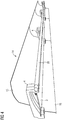
Figur 8 geht die Anbindung sämtlicher oben beschriebenen verschiedenen Ausführungsformen von Gepäckablagenmodulen mehr im Detail hervor. Wie die Querschnittansicht vonFigur 8 zeigt, ist der Halter 4 nicht nur, wie anhand vonFigur 6 erläutert, im hinteren oberen Bereich über den hakenförmigen Abschnitt 26 des Halters 4 und den stegförmigen Abschnitt 27 des Adapterprofils 28 angebunden, sondern zusätzlich im hinteren unteren Bereich des Halters 4. Dort zeigt das Adapterprofil einen in Richtung auf die Rückseite des unteren Bereichs des Halters 4 gerichteten, C-förmigen Profilbereich 29, der zur Anbindung des Halters 4 nutzbar ist. - Die Rückseite des Adapterprofils 28 ist wiederum an einem Seitenwandabschnitt 31, der zum Fahrzeugrohbau gehört, befestigt. Dies geschieht über zwei in Längsrichtung des Fahrzeugrohrbaus verlaufende C-Schienen 32, deren Stirnseiten jeweils an einer Rückseite des Adapterprofils 28 derart anliegen, dass eine geeignete Schraubverbindung unter Einsatz von Nutensteinen ermöglicht ist.
- Aus
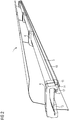
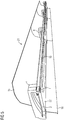
Figur 9 geht nunmehr hervor, dass das Gepäckablagenmodul 23, das hier hinsichtlich der Anbringung an dem Seitenwandabschnitt 31 stellvertretend für sämtliche, oben erläuterte Ausführungsformen für Gepäckablagenmodule steht, über zwei Adapterprofile 28 an den Seitenwandabschnitt 31 anbringbar ist. Außerdem zeigtFigur 9 , dass sich das rückwärtige Tragprofil 33 zwischen den Haltern 4 erstreckt und zudem in seinem unteren Bereich eine sich über die gesamte Länge des rückwertigen Tragprofils 33 erstreckende Aufnahmenut 34 aufweist, die zur hinteren Halterung der Auflageplatte 2 dient. Zudem ist ersichtlich, dass die Halter 4 in ihrem hinteren, unteren Bereich ebenfalls Aufnahmenuten 35 besitzen, die mit der Aufnahmenut 33 fluchten. Es ist hervorzuheben, dass inFigur 9 und auch in anderen Figuren die sich außen an die mit Bezugszeichen versehenen Halter 4 anschließenden Halter zu jeweils benachbarten Gepäckablagenmodulen gehören. Diese Halter liegen seitlich lediglich an den Haltern 4 an, so dass keine kraftübertragende Verbindung unter benachbarten Gepäckablagemodulen besteht. -
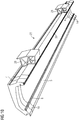
Figur 10 zeigt nun eine Ansicht des Gepäckablagenmoduls 23 von hinten. In Zusammensicht mit denFiguren 8 und9 ist ersichtlich, dass der Querschnitt des rückwärtigen Tragprofils 33 dem entsprechenden Querschnitt der Halter 4 entspricht. Insbesondere erstreckt sich der hakenförmige Abschnitt 26 im oberen hinteren Bereich über eine gesamte Länge des Gepäckablagenmoduls 23, und zwar von dem äußeren Ende des einen Halters 4 über das rückwärtige Tragprofil 33 bis zum äußeren Ende des gegenüberliegenden anderen Halters 4. Da das Gepäckablagenmodul 23 somit frei gegenüber den im vorliegenden Ausführungsbeispiel zwei Adapterprofilen 28 verschieblich ist, können sich in Längsrichtung des Schienenfahrzeugs aneinander anschließende Gepäckablagenmodule in einfacher Weise zueinander ausgerichtet werden.
Claims (12)
- Gepäckablagenmodul zum Aufbau einer Gepäckablage in einem Schienenfahrzeug, wobei das Gepäckablagenmodul (1, 18, 14, 21, 23, 24) eine Auflageplatte (2), die mittels wenigstens einem Halter (4) gegenüber einem Fahrzeugrohbau (31) des Schienenfahrzeugs fixierbar ist, ein rückwärtiges Tragprofil (33) und einen vorderen Tragholm (5) aufweist, dadurch gekennzeichnet, dass
das Gepäckablagenmodul (1, 18, 14, 21, 23, 24) an seinen beiden Enden jeweils einen Halter (4) aufweist, der als nach unten offener Bügel ausgebildet ist, wobei das rückwärtige Tragprofil (33) zur Anbindung an den Fahrzeugrohbau ausgebildet ist und sich die Auflageplatte (2) über eine gesamte Länge des Gepäckablagenmoduls (1, 18, 14, 21, 23, 24) erstreckt sowie in Aufnahmenuten (14, 35, 6, 34) der Halter (4), des rückwärtigen Tragprofils (33) und des vorderen Tragholms (5) gehalten ist. - Gepäckablagenmodul nach Anspruch 1,
dadurch gekennzeichnet, dass
der vordere Tragholm (5) entlang seiner Vorderseite eine langgestreckte, nutförmige Ausnehmung (6) zur Aufnahme eines Einbaumoduls aufweist. - Gepäckablagenmodul nach Anspruch 2,
dadurch gekennzeichnet, dass
das Einbaumodul als Sitzplatzreservierungsanzeige (9, 10), als Beleuchtungsvorrichtung, als Griffholm (20) oder Blindfeld 17 ausgebildet ist. - Gepäckablagenmodul nach einem der Ansprüche 1 bis 3,
dadurch gekennzeichnet, dass
der vordere Tragholm (5) an seiner der Ablageplatte (2) zugeordneten hinteren Seite ein Funktionselement trägt. - Gepäckablagenmodul nach Anspruch 4,
dadurch gekennzeichnet, dass
das Funktionselement als Lichtband, als eine Anordnung von Lautsprechern (25) und/oder als Fahrgastinformations-Anzeigevorrichtung (30) ausgebildet ist. - Gepäckablagenmodul nach einem der Ansprüche 1 bis 5,
dadurch gekennzeichnet, dass
das rückwärtige Tragprofil (33) in seinem oberen Bereich in Adapterprofile (28) eingehakt und in seinem unteren Bereich an den Adapterprofilen (28) fixiert ist, wobei die Adapterprofile (28) am Fahrzeugrohbau (31) befestigt sind. - Gepäckablagenmodul nach einem der Ansprüche 1 bis 6,
dadurch gekennzeichnet, dass
die Halter (4) an ihrer Vorderseite Aufnahmenuten (14) aufweisen, die derart angeordnet sind, dass seitlich vorstehende Laschen (7) des vorderen Tragholms (5) in diese Aufnahmenuten (14) einsetzbar sind. - Gepäckablagenmodul nach einem der Ansprüche 1 bis 7,
dadurch gekennzeichnet, dass
das rückwärtige Tragprofil (33) an seiner der Ablageplatte (2) zugeordneten vorderen Seite ein Funktionselement trägt. - Gepäckablagenmodul nach Anspruch 8,
dadurch gekennzeichnet, dass
das Funktionselement als Lichtband, als eine Anordnung von Leseleuchten und/oder als Fahrgastinformations-Anzeigevorrichtung (30) ausgebildet ist. - Gepäckablagenmodul nach einem der Ansprüche 1 bis 9,
dadurch gekennzeichnet, dass
das rückwärtige Tragprofil (33) Taschen oder Nuten zum Einstecken seitlicher Vouten-Verkleidungselemente (15, 16) aufweist. - Gepäckablagenmodul nach einem der Ansprüche 1 bis 10,
dadurch gekennzeichnet, dass
gegen die Unterseite der Auflageplatte (2) eine Verkleidungsblende (22) oder zwei unabhängige Einzel-Verkleidungselemente (12, 13) gesetzt ist, die an dem vorderen Tragholm (5) und/oder dem rückwärtigen Tragprofil (33) befestigt ist. - Gepäckablagenmodul nach einem der Ansprüche 1 bis 11,
dadurch gekennzeichnet, dass
die Halter (4), der vordere Tragholm (5) und das rückwärtige Tragprofil (33) untereinander lösbar verbunden sind.
Priority Applications (1)
| Application Number | Priority Date | Filing Date | Title |
|---|---|---|---|
| PL17701806T PL3386834T3 (pl) | 2016-02-11 | 2017-01-13 | Moduł półki bagażowej do budowy półki bagażowej w pojeździe szynowym |
Applications Claiming Priority (2)
| Application Number | Priority Date | Filing Date | Title |
|---|---|---|---|
| DE102016202077.3A DE102016202077A1 (de) | 2016-02-11 | 2016-02-11 | Gepäckablagenmodul zum Aufbau einer Gepäckablage in einem Schienenfahrzeug |
| PCT/EP2017/050630 WO2017137208A1 (de) | 2016-02-11 | 2017-01-13 | Gepäckablagenmodul zum aufbau einer gepäckablage in einem schienenfahrzeug |
Publications (2)
| Publication Number | Publication Date |
|---|---|
| EP3386834A1 EP3386834A1 (de) | 2018-10-17 |
| EP3386834B1 true EP3386834B1 (de) | 2020-02-26 |
Family
ID=57909583
Family Applications (1)
| Application Number | Title | Priority Date | Filing Date |
|---|---|---|---|
| EP17701806.6A Active EP3386834B1 (de) | 2016-02-11 | 2017-01-13 | Gepäckablagenmodul zum aufbau einer gepäckablage in einem schienenfahrzeug |
Country Status (9)
| Country | Link |
|---|---|
| EP (1) | EP3386834B1 (de) |
| CN (1) | CN209566925U (de) |
| DE (1) | DE102016202077A1 (de) |
| DK (1) | DK3386834T3 (de) |
| ES (1) | ES2786779T3 (de) |
| PL (1) | PL3386834T3 (de) |
| PT (1) | PT3386834T (de) |
| RU (1) | RU188149U1 (de) |
| WO (1) | WO2017137208A1 (de) |
Families Citing this family (3)
| Publication number | Priority date | Publication date | Assignee | Title |
|---|---|---|---|---|
| CN108819967B (zh) * | 2018-08-01 | 2024-08-30 | 青岛威奥轨道股份有限公司 | 一种动车用风道、侧顶板、行李架及照明集成结构 |
| CN109017850B (zh) * | 2018-08-28 | 2024-11-15 | 青岛威奥轨道股份有限公司 | 一种新型无框轻量化行李架 |
| DE102020102415A1 (de) * | 2020-01-31 | 2021-08-05 | Airbus Operations Gmbh | Staufachanordnung für eine Kabine eines Fahrzeugs |
Family Cites Families (10)
| Publication number | Priority date | Publication date | Assignee | Title |
|---|---|---|---|---|
| DE322997C (de) * | 1920-07-13 | Kranenberg & Schmitz | Gepaeckhalter fuer Eisenbahnwagen | |
| US2263123A (en) * | 1936-12-03 | 1941-11-18 | New York Central Railroad Co | Railway car |
| DE1025441B (de) * | 1954-10-25 | 1958-03-06 | Erich Mory | Gepaeckablage, insbesondere in Fahrzeugen fuer den Personenverkehr |
| US3348699A (en) * | 1965-12-28 | 1967-10-24 | Budd Co | Ladder-type rack, as for passenger vehicles |
| RU35960U1 (ru) * | 2003-11-18 | 2004-02-20 | Щербаков Валерий Тихонович | Полка багажная |
| JP4558550B2 (ja) * | 2005-03-17 | 2010-10-06 | 株式会社日立製作所 | 鉄道車両の荷物棚ユニット |
| DE102007052493A1 (de) | 2007-11-02 | 2009-05-14 | Siemens Ag | Gepäckablage für Schienenfahrzeuge |
| DE102011004894A1 (de) * | 2011-03-01 | 2012-09-06 | Siemens Aktiengesellschaft | Modulare Gepäckablage |
| DE102012015566A1 (de) * | 2012-08-06 | 2014-02-06 | SBF Spezialleuchten GmbH | Gepäckablage, insbesondere für eine Passagierkabine eines Schienenfahrzeuges |
| CN203623691U (zh) * | 2013-12-03 | 2014-06-04 | 今创集团股份有限公司 | 铁道客车行李架 |
-
2016
- 2016-02-11 DE DE102016202077.3A patent/DE102016202077A1/de not_active Ceased
-
2017
- 2017-01-13 RU RU2018131000U patent/RU188149U1/ru active
- 2017-01-13 DK DK17701806.6T patent/DK3386834T3/da active
- 2017-01-13 CN CN201790000592.4U patent/CN209566925U/zh active Active
- 2017-01-13 ES ES17701806T patent/ES2786779T3/es active Active
- 2017-01-13 WO PCT/EP2017/050630 patent/WO2017137208A1/de not_active Ceased
- 2017-01-13 PT PT177018066T patent/PT3386834T/pt unknown
- 2017-01-13 PL PL17701806T patent/PL3386834T3/pl unknown
- 2017-01-13 EP EP17701806.6A patent/EP3386834B1/de active Active
Non-Patent Citations (1)
| Title |
|---|
| None * |
Also Published As
| Publication number | Publication date |
|---|---|
| PT3386834T (pt) | 2020-04-01 |
| CN209566925U (zh) | 2019-11-01 |
| DE102016202077A1 (de) | 2017-08-17 |
| PL3386834T3 (pl) | 2020-07-27 |
| ES2786779T3 (es) | 2020-10-13 |
| WO2017137208A1 (de) | 2017-08-17 |
| EP3386834A1 (de) | 2018-10-17 |
| RU188149U1 (ru) | 2019-04-01 |
| DK3386834T3 (da) | 2020-05-04 |
Similar Documents
| Publication | Publication Date | Title |
|---|---|---|
| DE102007019539A1 (de) | Luftzufuhrvorrichtung für die Klimatisierung von Passagierräumen in Flugzeugen | |
| EP2495150B1 (de) | Modulare Gepäckablage | |
| EP2055610B1 (de) | Gepäckablage für Schienenfahrzeuge | |
| EP1101655A2 (de) | Fahrzeuginnenraumbeleuchtung | |
| DE4128234C1 (de) | ||
| DE102016202077A1 (de) | Gepäckablagenmodul zum Aufbau einer Gepäckablage in einem Schienenfahrzeug | |
| EP1302369B1 (de) | Deckenverkleidungs- und Luftleitsystem | |
| DE3820334C1 (en) | Arrangement for mounting a sun visor in a vehicle | |
| DE102008020051A1 (de) | Crashbox für eine Karosserie eines Kraftwagens | |
| EP3752388B1 (de) | Befestigung für innenausbauteile von fahrzeugen | |
| DE102005060480A1 (de) | Kraftfahrzeugsitz | |
| DE202013004468U1 (de) | Haltevorrichtung für ein Kennzeichenschild an Fahrzeugen | |
| DE102009024783B4 (de) | Befestigungsanordnung einer Leuchteinheit an einem Verkleidungsteil | |
| EP2334532B1 (de) | Kabine zur aufnahme von fahrgästen und/oder gütern | |
| EP3408156B1 (de) | Deckenbaueinheit für ein fahrzeug | |
| DE4416337B4 (de) | Einrichtung zum Präsentieren von Artikeln, insbesondere Elektrowerkzeugen | |
| DE202013103414U1 (de) | Dachträger für ein Kraftfahrzeug | |
| EP0627338B1 (de) | Einheitsteil-Sitz | |
| DE8802075U1 (de) | Tragvorrichtung für eine Wand- oder Deckenverkleidung | |
| DE2149810A1 (de) | Innenausruestungsteil fuer land-, luft- und wasserfahrzeuge | |
| EP3380383B1 (de) | Gepäckablagemodul für ein fahrzeug | |
| DE202013103831U1 (de) | Seilbremse, Spannset und Vorhangsystem | |
| DE102007040193B4 (de) | Fahrzeugaufbau | |
| DE10041899A1 (de) | Omnibus mit einem Podest im Passagierraum | |
| DE102004057647B4 (de) | Tragevorrichtung für Gegenstände an der Außenseite eines Kraftfahrzeugs |
Legal Events
| Date | Code | Title | Description |
|---|---|---|---|
| STAA | Information on the status of an ep patent application or granted ep patent |
Free format text: STATUS: UNKNOWN |
|
| STAA | Information on the status of an ep patent application or granted ep patent |
Free format text: STATUS: THE INTERNATIONAL PUBLICATION HAS BEEN MADE |
|
| PUAI | Public reference made under article 153(3) epc to a published international application that has entered the european phase |
Free format text: ORIGINAL CODE: 0009012 |
|
| STAA | Information on the status of an ep patent application or granted ep patent |
Free format text: STATUS: REQUEST FOR EXAMINATION WAS MADE |
|
| 17P | Request for examination filed |
Effective date: 20180706 |
|
| AK | Designated contracting states |
Kind code of ref document: A1 Designated state(s): AL AT BE BG CH CY CZ DE DK EE ES FI FR GB GR HR HU IE IS IT LI LT LU LV MC MK MT NL NO PL PT RO RS SE SI SK SM TR |
|
| AX | Request for extension of the european patent |
Extension state: BA ME |
|
| RAP1 | Party data changed (applicant data changed or rights of an application transferred) |
Owner name: SIEMENS MOBILITY GMBH |
|
| DAV | Request for validation of the european patent (deleted) | ||
| DAX | Request for extension of the european patent (deleted) | ||
| GRAP | Despatch of communication of intention to grant a patent |
Free format text: ORIGINAL CODE: EPIDOSNIGR1 |
|
| STAA | Information on the status of an ep patent application or granted ep patent |
Free format text: STATUS: GRANT OF PATENT IS INTENDED |
|
| INTG | Intention to grant announced |
Effective date: 20191022 |
|
| GRAS | Grant fee paid |
Free format text: ORIGINAL CODE: EPIDOSNIGR3 |
|
| GRAA | (expected) grant |
Free format text: ORIGINAL CODE: 0009210 |
|
| STAA | Information on the status of an ep patent application or granted ep patent |
Free format text: STATUS: THE PATENT HAS BEEN GRANTED |
|
| AK | Designated contracting states |
Kind code of ref document: B1 Designated state(s): AL AT BE BG CH CY CZ DE DK EE ES FI FR GB GR HR HU IE IS IT LI LT LU LV MC MK MT NL NO PL PT RO RS SE SI SK SM TR |
|
| REG | Reference to a national code |
Ref country code: GB Ref legal event code: FG4D Free format text: NOT ENGLISH |
|
| REG | Reference to a national code |
Ref country code: CH Ref legal event code: EP |
|
| REG | Reference to a national code |
Ref country code: DE Ref legal event code: R096 Ref document number: 502017003969 Country of ref document: DE |
|
| REG | Reference to a national code |
Ref country code: CH Ref legal event code: NV Representative=s name: SIEMENS SCHWEIZ AG, CH |
|
| REG | Reference to a national code |
Ref country code: AT Ref legal event code: REF Ref document number: 1237274 Country of ref document: AT Kind code of ref document: T Effective date: 20200315 |
|
| REG | Reference to a national code |
Ref country code: IE Ref legal event code: FG4D Free format text: LANGUAGE OF EP DOCUMENT: GERMAN |
|
| REG | Reference to a national code |
Ref country code: PT Ref legal event code: SC4A Ref document number: 3386834 Country of ref document: PT Date of ref document: 20200401 Kind code of ref document: T Free format text: AVAILABILITY OF NATIONAL TRANSLATION Effective date: 20200325 |
|
| REG | Reference to a national code |
Ref country code: DK Ref legal event code: T3 Effective date: 20200430 |
|
| REG | Reference to a national code |
Ref country code: NL Ref legal event code: FP |
|
| PG25 | Lapsed in a contracting state [announced via postgrant information from national office to epo] |
Ref country code: RS Free format text: LAPSE BECAUSE OF FAILURE TO SUBMIT A TRANSLATION OF THE DESCRIPTION OR TO PAY THE FEE WITHIN THE PRESCRIBED TIME-LIMIT Effective date: 20200226 Ref country code: FI Free format text: LAPSE BECAUSE OF FAILURE TO SUBMIT A TRANSLATION OF THE DESCRIPTION OR TO PAY THE FEE WITHIN THE PRESCRIBED TIME-LIMIT Effective date: 20200226 Ref country code: NO Free format text: LAPSE BECAUSE OF FAILURE TO SUBMIT A TRANSLATION OF THE DESCRIPTION OR TO PAY THE FEE WITHIN THE PRESCRIBED TIME-LIMIT Effective date: 20200526 |
|
| REG | Reference to a national code |
Ref country code: LT Ref legal event code: MG4D |
|
| PG25 | Lapsed in a contracting state [announced via postgrant information from national office to epo] |
Ref country code: BG Free format text: LAPSE BECAUSE OF FAILURE TO SUBMIT A TRANSLATION OF THE DESCRIPTION OR TO PAY THE FEE WITHIN THE PRESCRIBED TIME-LIMIT Effective date: 20200526 Ref country code: SE Free format text: LAPSE BECAUSE OF FAILURE TO SUBMIT A TRANSLATION OF THE DESCRIPTION OR TO PAY THE FEE WITHIN THE PRESCRIBED TIME-LIMIT Effective date: 20200226 Ref country code: GR Free format text: LAPSE BECAUSE OF FAILURE TO SUBMIT A TRANSLATION OF THE DESCRIPTION OR TO PAY THE FEE WITHIN THE PRESCRIBED TIME-LIMIT Effective date: 20200527 Ref country code: HR Free format text: LAPSE BECAUSE OF FAILURE TO SUBMIT A TRANSLATION OF THE DESCRIPTION OR TO PAY THE FEE WITHIN THE PRESCRIBED TIME-LIMIT Effective date: 20200226 Ref country code: LV Free format text: LAPSE BECAUSE OF FAILURE TO SUBMIT A TRANSLATION OF THE DESCRIPTION OR TO PAY THE FEE WITHIN THE PRESCRIBED TIME-LIMIT Effective date: 20200226 Ref country code: IS Free format text: LAPSE BECAUSE OF FAILURE TO SUBMIT A TRANSLATION OF THE DESCRIPTION OR TO PAY THE FEE WITHIN THE PRESCRIBED TIME-LIMIT Effective date: 20200626 |
|
| REG | Reference to a national code |
Ref country code: ES Ref legal event code: FG2A Ref document number: 2786779 Country of ref document: ES Kind code of ref document: T3 Effective date: 20201013 |
|
| PG25 | Lapsed in a contracting state [announced via postgrant information from national office to epo] |
Ref country code: SK Free format text: LAPSE BECAUSE OF FAILURE TO SUBMIT A TRANSLATION OF THE DESCRIPTION OR TO PAY THE FEE WITHIN THE PRESCRIBED TIME-LIMIT Effective date: 20200226 Ref country code: RO Free format text: LAPSE BECAUSE OF FAILURE TO SUBMIT A TRANSLATION OF THE DESCRIPTION OR TO PAY THE FEE WITHIN THE PRESCRIBED TIME-LIMIT Effective date: 20200226 Ref country code: SM Free format text: LAPSE BECAUSE OF FAILURE TO SUBMIT A TRANSLATION OF THE DESCRIPTION OR TO PAY THE FEE WITHIN THE PRESCRIBED TIME-LIMIT Effective date: 20200226 Ref country code: EE Free format text: LAPSE BECAUSE OF FAILURE TO SUBMIT A TRANSLATION OF THE DESCRIPTION OR TO PAY THE FEE WITHIN THE PRESCRIBED TIME-LIMIT Effective date: 20200226 Ref country code: LT Free format text: LAPSE BECAUSE OF FAILURE TO SUBMIT A TRANSLATION OF THE DESCRIPTION OR TO PAY THE FEE WITHIN THE PRESCRIBED TIME-LIMIT Effective date: 20200226 |
|
| REG | Reference to a national code |
Ref country code: DE Ref legal event code: R097 Ref document number: 502017003969 Country of ref document: DE |
|
| PLBE | No opposition filed within time limit |
Free format text: ORIGINAL CODE: 0009261 |
|
| STAA | Information on the status of an ep patent application or granted ep patent |
Free format text: STATUS: NO OPPOSITION FILED WITHIN TIME LIMIT |
|
| 26N | No opposition filed |
Effective date: 20201127 |
|
| PG25 | Lapsed in a contracting state [announced via postgrant information from national office to epo] |
Ref country code: SI Free format text: LAPSE BECAUSE OF FAILURE TO SUBMIT A TRANSLATION OF THE DESCRIPTION OR TO PAY THE FEE WITHIN THE PRESCRIBED TIME-LIMIT Effective date: 20200226 |
|
| PG25 | Lapsed in a contracting state [announced via postgrant information from national office to epo] |
Ref country code: MC Free format text: LAPSE BECAUSE OF FAILURE TO SUBMIT A TRANSLATION OF THE DESCRIPTION OR TO PAY THE FEE WITHIN THE PRESCRIBED TIME-LIMIT Effective date: 20200226 |
|
| PG25 | Lapsed in a contracting state [announced via postgrant information from national office to epo] |
Ref country code: LU Free format text: LAPSE BECAUSE OF NON-PAYMENT OF DUE FEES Effective date: 20210113 |
|
| PG25 | Lapsed in a contracting state [announced via postgrant information from national office to epo] |
Ref country code: IE Free format text: LAPSE BECAUSE OF NON-PAYMENT OF DUE FEES Effective date: 20210113 |
|
| PGFP | Annual fee paid to national office [announced via postgrant information from national office to epo] |
Ref country code: PT Payment date: 20221222 Year of fee payment: 7 |
|
| PGFP | Annual fee paid to national office [announced via postgrant information from national office to epo] |
Ref country code: DK Payment date: 20230123 Year of fee payment: 7 Ref country code: AT Payment date: 20221209 Year of fee payment: 7 |
|
| PGFP | Annual fee paid to national office [announced via postgrant information from national office to epo] |
Ref country code: TR Payment date: 20230113 Year of fee payment: 7 Ref country code: BE Payment date: 20230119 Year of fee payment: 7 |
|
| PG25 | Lapsed in a contracting state [announced via postgrant information from national office to epo] |
Ref country code: CY Free format text: LAPSE BECAUSE OF FAILURE TO SUBMIT A TRANSLATION OF THE DESCRIPTION OR TO PAY THE FEE WITHIN THE PRESCRIBED TIME-LIMIT Effective date: 20200226 |
|
| PGFP | Annual fee paid to national office [announced via postgrant information from national office to epo] |
Ref country code: NL Payment date: 20230102 Year of fee payment: 7 |
|
| PG25 | Lapsed in a contracting state [announced via postgrant information from national office to epo] |
Ref country code: HU Free format text: LAPSE BECAUSE OF FAILURE TO SUBMIT A TRANSLATION OF THE DESCRIPTION OR TO PAY THE FEE WITHIN THE PRESCRIBED TIME-LIMIT; INVALID AB INITIO Effective date: 20170113 |
|
| PG25 | Lapsed in a contracting state [announced via postgrant information from national office to epo] |
Ref country code: MK Free format text: LAPSE BECAUSE OF FAILURE TO SUBMIT A TRANSLATION OF THE DESCRIPTION OR TO PAY THE FEE WITHIN THE PRESCRIBED TIME-LIMIT Effective date: 20200226 |
|
| PGFP | Annual fee paid to national office [announced via postgrant information from national office to epo] |
Ref country code: CZ Payment date: 20240108 Year of fee payment: 8 |
|
| PGFP | Annual fee paid to national office [announced via postgrant information from national office to epo] |
Ref country code: PL Payment date: 20240104 Year of fee payment: 8 |
|
| REG | Reference to a national code |
Ref country code: DK Ref legal event code: EBP Effective date: 20240131 |
|
| REG | Reference to a national code |
Ref country code: NL Ref legal event code: MM Effective date: 20240201 |
|
| REG | Reference to a national code |
Ref country code: AT Ref legal event code: MM01 Ref document number: 1237274 Country of ref document: AT Kind code of ref document: T Effective date: 20240113 |
|
| PG25 | Lapsed in a contracting state [announced via postgrant information from national office to epo] |
Ref country code: MT Free format text: LAPSE BECAUSE OF FAILURE TO SUBMIT A TRANSLATION OF THE DESCRIPTION OR TO PAY THE FEE WITHIN THE PRESCRIBED TIME-LIMIT Effective date: 20200226 |
|
| PG25 | Lapsed in a contracting state [announced via postgrant information from national office to epo] |
Ref country code: PT Free format text: LAPSE BECAUSE OF NON-PAYMENT OF DUE FEES Effective date: 20240715 |
|
| PG25 | Lapsed in a contracting state [announced via postgrant information from national office to epo] |
Ref country code: BE Free format text: LAPSE BECAUSE OF NON-PAYMENT OF DUE FEES Effective date: 20240131 |
|
| PG25 | Lapsed in a contracting state [announced via postgrant information from national office to epo] |
Ref country code: NL Free format text: LAPSE BECAUSE OF NON-PAYMENT OF DUE FEES Effective date: 20240201 |
|
| PG25 | Lapsed in a contracting state [announced via postgrant information from national office to epo] |
Ref country code: AT Free format text: LAPSE BECAUSE OF NON-PAYMENT OF DUE FEES Effective date: 20240113 |
|
| PG25 | Lapsed in a contracting state [announced via postgrant information from national office to epo] |
Ref country code: PT Free format text: LAPSE BECAUSE OF NON-PAYMENT OF DUE FEES Effective date: 20240715 Ref country code: NL Free format text: LAPSE BECAUSE OF NON-PAYMENT OF DUE FEES Effective date: 20240201 Ref country code: BE Free format text: LAPSE BECAUSE OF NON-PAYMENT OF DUE FEES Effective date: 20240131 Ref country code: AT Free format text: LAPSE BECAUSE OF NON-PAYMENT OF DUE FEES Effective date: 20240113 |
|
| REG | Reference to a national code |
Ref country code: BE Ref legal event code: MM Effective date: 20240131 |
|
| PG25 | Lapsed in a contracting state [announced via postgrant information from national office to epo] |
Ref country code: DK Free format text: LAPSE BECAUSE OF NON-PAYMENT OF DUE FEES Effective date: 20240131 |
|
| PG25 | Lapsed in a contracting state [announced via postgrant information from national office to epo] |
Ref country code: DK Free format text: LAPSE BECAUSE OF NON-PAYMENT OF DUE FEES Effective date: 20240131 |
|
| PGFP | Annual fee paid to national office [announced via postgrant information from national office to epo] |
Ref country code: ES Payment date: 20250422 Year of fee payment: 9 |
|
| PGFP | Annual fee paid to national office [announced via postgrant information from national office to epo] |
Ref country code: CH Payment date: 20250403 Year of fee payment: 9 |
|
| REG | Reference to a national code |
Ref country code: DE Ref legal event code: R081 Ref document number: 502017003969 Country of ref document: DE Owner name: SIEMENS MOBILITY GMBH, DE Free format text: FORMER OWNER: SIEMENS MOBILITY GMBH, 81739 MUENCHEN, DE |
|
| PG25 | Lapsed in a contracting state [announced via postgrant information from national office to epo] |
Ref country code: CZ Free format text: LAPSE BECAUSE OF NON-PAYMENT OF DUE FEES Effective date: 20250113 |
|
| REG | Reference to a national code |
Ref country code: CH Ref legal event code: U11 Free format text: ST27 STATUS EVENT CODE: U-0-0-U10-U11 (AS PROVIDED BY THE NATIONAL OFFICE) Effective date: 20260402 |
|
| PGFP | Annual fee paid to national office [announced via postgrant information from national office to epo] |
Ref country code: GB Payment date: 20260210 Year of fee payment: 10 |
|
| PGFP | Annual fee paid to national office [announced via postgrant information from national office to epo] |
Ref country code: DE Payment date: 20260320 Year of fee payment: 10 |
|
| PGFP | Annual fee paid to national office [announced via postgrant information from national office to epo] |
Ref country code: IT Payment date: 20260127 Year of fee payment: 10 |
|
| PGFP | Annual fee paid to national office [announced via postgrant information from national office to epo] |
Ref country code: FR Payment date: 20260122 Year of fee payment: 10 |