EP3386904B1 - Verfahren zum befüllen einer polimerischen behälters - Google Patents
Verfahren zum befüllen einer polimerischen behälters Download PDFInfo
- Publication number
- EP3386904B1 EP3386904B1 EP15910330.8A EP15910330A EP3386904B1 EP 3386904 B1 EP3386904 B1 EP 3386904B1 EP 15910330 A EP15910330 A EP 15910330A EP 3386904 B1 EP3386904 B1 EP 3386904B1
- Authority
- EP
- European Patent Office
- Prior art keywords
- container
- top load
- load force
- applying
- cooling
- Prior art date
- Legal status (The legal status is an assumption and is not a legal conclusion. Google has not performed a legal analysis and makes no representation as to the accuracy of the status listed.)
- Active
Links
Images


Classifications
-
- B—PERFORMING OPERATIONS; TRANSPORTING
- B67—OPENING, CLOSING OR CLEANING BOTTLES, JARS OR SIMILAR CONTAINERS; LIQUID HANDLING
- B67C—CLEANING, FILLING WITH LIQUIDS OR SEMILIQUIDS, OR EMPTYING, OF BOTTLES, JARS, CANS, CASKS, BARRELS, OR SIMILAR CONTAINERS, NOT OTHERWISE PROVIDED FOR; FUNNELS
- B67C3/00—Bottling liquids or semiliquids; Filling jars or cans with liquids or semiliquids using bottling or like apparatus; Filling casks or barrels with liquids or semiliquids
- B67C3/02—Bottling liquids or semiliquids; Filling jars or cans with liquids or semiliquids using bottling or like apparatus
- B67C3/22—Details
-
- B—PERFORMING OPERATIONS; TRANSPORTING
- B65—CONVEYING; PACKING; STORING; HANDLING THIN OR FILAMENTARY MATERIAL
- B65C—LABELLING OR TAGGING MACHINES, APPARATUS, OR PROCESSES
- B65C3/00—Labelling other than flat surfaces
- B65C3/06—Affixing labels to short rigid containers
- B65C3/08—Affixing labels to short rigid containers to container bodies
-
- B—PERFORMING OPERATIONS; TRANSPORTING
- B65—CONVEYING; PACKING; STORING; HANDLING THIN OR FILAMENTARY MATERIAL
- B65C—LABELLING OR TAGGING MACHINES, APPARATUS, OR PROCESSES
- B65C9/00—Details of labelling machines or apparatus
- B65C9/06—Devices for presenting articles in predetermined attitude or position at labelling station
-
- B—PERFORMING OPERATIONS; TRANSPORTING
- B67—OPENING, CLOSING OR CLEANING BOTTLES, JARS OR SIMILAR CONTAINERS; LIQUID HANDLING
- B67C—CLEANING, FILLING WITH LIQUIDS OR SEMILIQUIDS, OR EMPTYING, OF BOTTLES, JARS, CANS, CASKS, BARRELS, OR SIMILAR CONTAINERS, NOT OTHERWISE PROVIDED FOR; FUNNELS
- B67C7/00—Concurrent cleaning, filling, and closing of bottles; Processes or devices for at least two of these operations
-
- B—PERFORMING OPERATIONS; TRANSPORTING
- B29—WORKING OF PLASTICS; WORKING OF SUBSTANCES IN A PLASTIC STATE IN GENERAL
- B29C—SHAPING OR JOINING OF PLASTICS; SHAPING OF MATERIAL IN A PLASTIC STATE, NOT OTHERWISE PROVIDED FOR; AFTER-TREATMENT OF THE SHAPED PRODUCTS, e.g. REPAIRING
- B29C49/00—Blow-moulding, i.e. blowing a preform or parison to a desired shape within a mould; Apparatus therefor
- B29C49/42—Component parts, details or accessories; Auxiliary operations
- B29C49/4273—Auxiliary operations after the blow-moulding operation not otherwise provided for
-
- B—PERFORMING OPERATIONS; TRANSPORTING
- B29—WORKING OF PLASTICS; WORKING OF SUBSTANCES IN A PLASTIC STATE IN GENERAL
- B29K—INDEXING SCHEME ASSOCIATED WITH SUBCLASSES B29B, B29C OR B29D, RELATING TO MOULDING MATERIALS OR TO MATERIALS FOR MOULDS, REINFORCEMENTS, FILLERS OR PREFORMED PARTS, e.g. INSERTS
- B29K2067/00—Use of polyesters or derivatives thereof, as moulding material
- B29K2067/003—PET, i.e. poylethylene terephthalate
-
- B—PERFORMING OPERATIONS; TRANSPORTING
- B29—WORKING OF PLASTICS; WORKING OF SUBSTANCES IN A PLASTIC STATE IN GENERAL
- B29L—INDEXING SCHEME ASSOCIATED WITH SUBCLASS B29C, RELATING TO PARTICULAR ARTICLES
- B29L2031/00—Other particular articles
- B29L2031/712—Containers; Packaging elements or accessories, Packages
- B29L2031/7158—Bottles
-
- B—PERFORMING OPERATIONS; TRANSPORTING
- B65—CONVEYING; PACKING; STORING; HANDLING THIN OR FILAMENTARY MATERIAL
- B65D—CONTAINERS FOR STORAGE OR TRANSPORT OF ARTICLES OR MATERIALS, e.g. BAGS, BARRELS, BOTTLES, BOXES, CANS, CARTONS, CRATES, DRUMS, JARS, TANKS, HOPPERS, FORWARDING CONTAINERS; ACCESSORIES, CLOSURES, OR FITTINGS THEREFOR; PACKAGING ELEMENTS; PACKAGES
- B65D1/00—Rigid or semi-rigid containers having bodies formed in one piece, e.g. by casting metallic material, by moulding plastics, by blowing vitreous material, by throwing ceramic material, by moulding pulped fibrous material or by deep-drawing operations performed on sheet material
- B65D1/02—Bottles or similar containers with necks or like restricted apertures, designed for pouring contents
- B65D1/0223—Bottles or similar containers with necks or like restricted apertures, designed for pouring contents characterised by shape
- B65D1/023—Neck construction
- B65D1/0246—Closure retaining means, e.g. beads, screw-threads
-
- B—PERFORMING OPERATIONS; TRANSPORTING
- B65—CONVEYING; PACKING; STORING; HANDLING THIN OR FILAMENTARY MATERIAL
- B65D—CONTAINERS FOR STORAGE OR TRANSPORT OF ARTICLES OR MATERIALS, e.g. BAGS, BARRELS, BOTTLES, BOXES, CANS, CARTONS, CRATES, DRUMS, JARS, TANKS, HOPPERS, FORWARDING CONTAINERS; ACCESSORIES, CLOSURES, OR FITTINGS THEREFOR; PACKAGING ELEMENTS; PACKAGES
- B65D1/00—Rigid or semi-rigid containers having bodies formed in one piece, e.g. by casting metallic material, by moulding plastics, by blowing vitreous material, by throwing ceramic material, by moulding pulped fibrous material or by deep-drawing operations performed on sheet material
- B65D1/02—Bottles or similar containers with necks or like restricted apertures, designed for pouring contents
- B65D1/0223—Bottles or similar containers with necks or like restricted apertures, designed for pouring contents characterised by shape
- B65D1/0261—Bottom construction
- B65D1/0276—Bottom construction having a continuous contact surface, e.g. Champagne-type bottom
-
- B—PERFORMING OPERATIONS; TRANSPORTING
- B65—CONVEYING; PACKING; STORING; HANDLING THIN OR FILAMENTARY MATERIAL
- B65D—CONTAINERS FOR STORAGE OR TRANSPORT OF ARTICLES OR MATERIALS, e.g. BAGS, BARRELS, BOTTLES, BOXES, CANS, CARTONS, CRATES, DRUMS, JARS, TANKS, HOPPERS, FORWARDING CONTAINERS; ACCESSORIES, CLOSURES, OR FITTINGS THEREFOR; PACKAGING ELEMENTS; PACKAGES
- B65D2501/00—Containers having bodies formed in one piece
- B65D2501/0009—Bottles or similar containers with necks or like restricted apertures designed for pouring contents
- B65D2501/0018—Ribs
- B65D2501/0036—Hollow circonferential ribs
-
- B—PERFORMING OPERATIONS; TRANSPORTING
- B67—OPENING, CLOSING OR CLEANING BOTTLES, JARS OR SIMILAR CONTAINERS; LIQUID HANDLING
- B67C—CLEANING, FILLING WITH LIQUIDS OR SEMILIQUIDS, OR EMPTYING, OF BOTTLES, JARS, CANS, CASKS, BARRELS, OR SIMILAR CONTAINERS, NOT OTHERWISE PROVIDED FOR; FUNNELS
- B67C3/00—Bottling liquids or semiliquids; Filling jars or cans with liquids or semiliquids using bottling or like apparatus; Filling casks or barrels with liquids or semiliquids
- B67C3/02—Bottling liquids or semiliquids; Filling jars or cans with liquids or semiliquids using bottling or like apparatus
- B67C3/22—Details
- B67C2003/226—Additional process steps or apparatuses related to filling with hot liquids, e.g. after-treatment
-
- B—PERFORMING OPERATIONS; TRANSPORTING
- B67—OPENING, CLOSING OR CLEANING BOTTLES, JARS OR SIMILAR CONTAINERS; LIQUID HANDLING
- B67C—CLEANING, FILLING WITH LIQUIDS OR SEMILIQUIDS, OR EMPTYING, OF BOTTLES, JARS, CANS, CASKS, BARRELS, OR SIMILAR CONTAINERS, NOT OTHERWISE PROVIDED FOR; FUNNELS
- B67C3/00—Bottling liquids or semiliquids; Filling jars or cans with liquids or semiliquids using bottling or like apparatus; Filling casks or barrels with liquids or semiliquids
- B67C3/02—Bottling liquids or semiliquids; Filling jars or cans with liquids or semiliquids using bottling or like apparatus
- B67C3/22—Details
- B67C2003/227—Additional apparatus related to blow-moulding of the containers, e.g. a complete production line forming filled containers from preforms
Definitions
- the present disclosure relates to a method for filling a polymeric container, comprising amongst other steps applying a top load force to the container.
- PET containers are now being used more than ever to package numerous commodities previously supplied in glass containers.
- PET is a crystallizable polymer, meaning that it is available in an amorphous form or a semi-crystalline form.
- the ability of a PET container to maintain its material integrity relates to the percentage of the PET container in crystalline form, also known as the "crystallinity" of the PET container.
- Container manufacturers use mechanical processing and thermal processing to increase the PET polymer crystallinity of a container.
- Mechanical processing involves orienting the amorphous material to achieve strain hardening. This processing commonly involves stretching an injection molded PET preform along a longitudinal axis and expanding the PET preform along a transverse or radial axis to form a PET container. The combination promotes what manufacturers define as biaxial orientation of the molecular structure in the container.
- Manufacturers of PET containers currently use mechanical processing to produce PET containers having approximately 20% crystallinity in the container's sidewall.
- Thermal processing involves heating the material (either amorphous or semi-crystalline) to promote crystal growth.
- thermal processing of PET material results in a spherulitic morphology that interferes with the transmission of light. In other words, the resulting crystalline material is opaque, and thus, generally undesirable.
- thermal processing results in higher crystallinity and excellent clarity for those portions of the container having biaxial molecular orientation.
- the thermal processing of an oriented PET container typically includes blow molding a PET preform against a mold heated to a temperature of approximately approximately 121°C - 177°C (250°F - 350°F), and holding the blown container against the heated mold for approximately two (2) to five (5) seconds.
- Manufacturers of PET juice bottles, which must be hot-filled at approximately 85°C (185°F) currently use heat setting to produce PET bottles having an overall crystallinity in the range of approximately 25%-35%.
- a system and a method for pressurizing a plastic container including an actuator, a base unit including a heating surface, and a dispensing device.
- the actuator includes a body portion and a holding/securing member configured to hold or secure a portion of the container.
- the actuator may be configured to apply a force or pressure from the bottom on the container to contact the base unit.
- the base unit is configured to receive a base portion of the container, wherein the heating surface is configured for heating the base portion of the container, and the dispensing device is configured to introduce an inert gas into the container.
- an object of the invention to disclose an improved method for hot filling a container, whereby a certain vacuum within the container can be obtained after hot filling and wherein the final height of the container can be reduced upon filling.
- the present teachings provide for a method for manufacturing and filling a container.
- the method includes blow molding the container from a preform.
- the container is then hot filled, capped, and cooled.
- After cooling, the container is labeled.
- a top load force is applied to the container at least one of: before cooling the container; during cooling of the container; after cooling the container and before labeling the container; during labeling of the container; and after labeling the container in order to reverse any dents in the container formed during the method of manufacturing and filling, and reduce residual vacuum within the container.
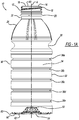
- Figure 1A illustrates the container 10 in an as-blown, pre-filled configuration.
- Figure 1B illustrates the container 10 after being hot-filled and subsequently cooled, with the as-blown position shown at AB.
- Figure 1C illustrates the container 10 subject to top load pressure, with the as-blown position shown at AB.
- Figure 1D illustrates the container 10 subject to additional top load pressure, with the as-blown position shown at AB.
- the container 10 can be any suitable container for storing any suitable commodity, such as liquid beverages, food, or other hot-fill type materials.
- the container 10 can have any suitable shape or size, such as 0.59 litres (20 ounces) as illustrated.
- Any suitable material can be used to manufacture the container 10, such as a suitable blow-molded thermoplastic, including PET, LDPE, HDPE, PP, PS, and the like.
- the container 10 generally includes a finish 12 defining an opening 14 at a first or upper end 16 of the container 10.
- the finish 12 includes threads 18 at an outer surface thereof, which are configured to cooperate with a suitable closure for closing the opening 14. In addition to, or in place of, the threads 18, any suitable feature for cooperating with a closure to close the opening 14 can be included.
- the threads 18 are between the opening 14 and a support ring 20 of the finish 12.
- a neck portion 22 Extending from the support ring 20 on a side thereof opposite to the threads 18 is a neck portion 22.
- the neck portion 22 extends from the support ring 20 to a shoulder portion 24 of the container 10.
- the shoulder portion 24 tapers outward from the neck portion 22 in the direction of a main body portion 30.
- an inwardly tapered portion 26 Between the shoulder portion 24 and the main body portion 30 is an inwardly tapered portion 26.
- the inwardly tapered portion 26 provides the container 10 with a reduced diameter portion, which can be the smallest diameter portion of the container 10 to increase the strength of the container 10.
- the main body 30 extends to a second or lower end 40 of the container 10.
- the second or lower end 40 is at an end of the container 10 opposite to the first or upper end 16.
- a longitudinal axis A of the container 10 extends through an axial center of the container 10 between the first or upper end 16 and the second or lower end 40.
- the main body portion 30 includes a sidewall 32, which extends to a base portion 50 of the container 10 (further illustrated in Figures 2 and 3 ).
- the sidewall 32 defines an internal volume 34 of the container 10 at an interior surface thereof.
- the sidewall 32 may be tapered inward towards the longitudinal axis A at one or more areas of the sidewall 32 in order to define recesses or ribs 36 at an exterior surface of the sidewall 32.
- the sidewall 32 defines five recesses or ribs 36a-36e.
- any suitable number of recesses or ribs 36 can be defined.
- the ribs 36 can be horizontal as illustrated, or can have any other suitable size or shape.
- the ribs 36 can be curved, as illustrated in U.S. Patent No.
- the ribs 36 can have any suitable external diameter, which may vary amongst the different ribs 36 or remain constant.
- the first recess or rib 36a and the fourth recess or rib 36d can each have a diameter that is less than, and a height that is greater than, the second, third, and fifth recesses or ribs 36b, 36c, and 36e.
- the ribs 36 can articulate about the sidewall 32 to arrive at a vacuum absorbed position, as illustrated in Figure 1D for example.
- the ribs 36 can be vacuum ribs.
- the ribs 36 can also provide the container 10 with reinforcement features, thereby providing the container 10 with improved structural integrity and stability, which allows the container 10 to be thinner and lighter.
- the larger ribs 36a and 36d will have a greater vacuum response. Smaller ribs 36b, 36c, and 36e will provide the container with improved structural integrity.
- Horizontal rib 36b includes an upper wall 80 and a lower wall 82 separated by an inner curved wall 84.
- Inner curved wall 84 is in part defined by a relatively sharp innermost radius r1. Sharp innermost radius r1 can lie within the range of about 0,25 mm (0.01 inches) to about 0,76 mm (0.03 inches).
- the relatively sharp innermost radius r1 of inner curved wall 84 facilitates improved material flow during blow molding of the plastic container 10, thus enabling formation of relatively deep horizontal ribs 36.
- Horizontal rib 36b can include an upper outer radius r2 and a lower outer radius r3.
- both the upper outer radius r2 and the lower outer radius r3 each lie within the range of about 1,78 mm (0.07 inches) to about 3,56 mm (0.14 inches).
- the upper outer radius r2 and the lower outer radius r3 may be equal to each other or differ from one another.
- the sum of the upper outer radius r2 and the lower outer radius r3 will be equal to or greater than about 3,56 mm (0.14 inches) and less than about 7,11 mm (0.28 inches).
- horizontal rib 36b (as well as the other horizontal ribs 36a and 36c-36e), further includes an upper inner radius r4 and a lower inner radius r5.
- the upper inner radius r4 and the lower inner radius r5 each lie within the range of about 2,03 mm (0.08 inches) to about 2,79 mm (0.11 inches).
- the upper inner radius r4 and the lower inner radius r5 may be equal to each other or different from one another.
- the sum of the upper inner radius r4 and the lower inner radius r5 can be equal to or greater than about 4.06 mm (0.16 inches) and less than about 5.59 mm (0.22 inches).
- Horizontal rib 36b can have a rib depth RD of about 3,05 mm (0.12 inches) and a rib width RW of about 5.59 mm (0.22 inches) (as can any of the other ribs 36), as measured from the upper extent of the upper outer radius r2 and the lower extent of the lower outer radius r3.
- horizontal rib 36b (as well as the other horizontal ribs 36) has a rib width RW to rib depth RD ratio.
- the rib width RW to rib depth RD ratio is preferably in the range of about 1.6 to about 2.0.
- Horizontal ribs 36 are designed to achieve optimal performance with regard to vacuum absorption, top load strength and dent resistance. Horizontal ribs 36 are designed to compress slightly in a vertical direction to accommodate and absorb vacuum forces resulting from hot-filling, capping and cooling of the container contents. Horizontal ribs 36 are designed to compress further when the filled container is exposed to top load forces in accordance with the present teachings, as described further herein.
- the above-described horizontal rib 36b radii, walls, depth and width in combination form a rib angle A.
- the rib angle A of an unfilled plastic container 10 starts at an as-blown angle that may be about 58 degrees. After hot-filling, capping and cooling of the container contents, and applying top load force pursuant to the present teachings (see blocks 130A-130E of Figure 6 described herein), the rib angle A is reduced.
- the horizontal ribs 36 are designed so that the upper wall 80 and the lower wall 82 never come into contact with each other as a result of vacuum or top load forces. Instead horizontal ribs 36 are designed to allow the plastic container 10 to reach a state wherein the plastic container 10 is supported in part by the product inside when exposed to top load forces thereby preventing permanent distortion of the plastic container 10.
- Horizontal lands 86 are generally flat in vertical cross-section as molded. When the plastic container 10 is subjected to vacuum and/or top load forces, horizontal lands 86 are designed to bulge slightly outward in vertical cross-section to aid the plastic container 10 in absorbing these forces in a uniform way.
- the base portion 50 illustrated and described is an exemplary base portion.
- the present teachings provide for use of any suitable base portion having any base geometry.
- any suitable rigid base can be used, such as any suitable non-vacuum absorbing base, or any suitable flexible base can be used, such as a vacuum absorbing base.
- the base portions set forth in the following documents are examples of base designs that may be used: U.S. Pub. No. 2014-0190927 titled "Heat-Set Container and Mold System Thereof" (published July 10, 2014); U.S. Patent Application Serial No. 14/424,569 titled "Lightweight Container Base” (filed February 27, 2015); International Application No.
- the exemplary base portion 50 illustrated generally includes a central push-up portion 52 at an axial center thereof, through which the longitudinal axis A extends.
- the central push-up portion 52 can be sized to stack with closures of a neighboring container 10, and also be sized to modify and optimize movement of the base portion 50 under vacuum.
- the diaphragm 54 can include any number of strengthening features defined therein.
- a plurality of first outer ribs 56a and a plurality of second outer ribs 56b can be defined in the diaphragm 54.
- the first and second outer ribs 56a and 56b extend radially with respect to the longitudinal axis A.
- the first outer ribs 56a extend entirely across the diaphragm 54.
- the second outer ribs 56b extend across less than an entirety of the diaphragm 54, such as across an outermost portion of the diameter 54.
- the first and the second outer ribs 56a and 56b can have any other suitable shape or configuration.
- Any suitable strengthening feature(s) can be included in the diaphragm 54, such as dimples, triangles, etc.
- the base portion 50 can further includes a fold 60 at an outer diameter thereof.
- the diaphragm 54 provides a standing surface of the base portion 50 and the overall container 10.
- the diaphragm 54 is at the second or lower end 40 of the container 10 and the outer folded portion 64 is arranged upward and spaced apart from the second or lower end 40.
- vacuum forces within the container 10 cause the diaphragm 54 to retract and move towards the first or upper end 16 until the diaphragm 54 is generally coplanar with the outer folded portion 64, or closer to the upper end 16 than the outer folded portion 64.
- the standing surface of the base 50 includes both the diaphragm 54 and the outer folded portion 64, or only the outer folded portion 64.
- the container 10 is supported on the standing surface by the diaphragm 54 of the base portion 50.
- the base portion 50 responds to the increase in internal vacuum and reduction of internal volume due to the cooling of the filled contents.
- the diaphragm 54 pivots and angles upwards into the container towards the first or upper end 16.
- the method 110 can be used to manufacture and fill any other suitable container according to the present teachings having the following: at least one horizontal compression rib, such as any of the ribs 36 or the ribs disclosed in U.S. Pat. No. 8,496,130 ; and a base portion having a constrained/rigid base geometry, such as the base portion 50 or the base portions disclosed in U.S. Pub. No. 2014-0190927 , U.S. Patent Application Serial No. 14/424,569 , and International Application No. PCT/US14/52148 .
- at least one horizontal compression rib such as any of the ribs 36 or the ribs disclosed in U.S. Pat. No. 8,496,130
- a base portion having a constrained/rigid base geometry such as the base portion 50 or the base portions disclosed in U.S. Pub. No. 2014-0190927 , U.S. Patent Application Serial No. 14/424,569 , and International Application No. PCT/US14/52148 .
- the container 10 is blow molded from a preform to the as-blown configuration of Figure 1A .
- the container 10 is hot filled at block 114 using any suitable hot fill, retort, or pasteurization process.
- the container 10 is capped immediately after being filled.
- the container 10 is cooled in any suitable manner, such as in a cooling tunnel where cold water is sprayed onto the container 10.
- the container 10 can be transported to the cooling tunnel with a conveyor, for example.
- Figure 1B as the container 10 cools, the fluid contents therein contract and vacuum is developed within the container 10. This pulls the base portion 50 up towards the upper end 16 due to internal vacuum.
- the overall height of the container 10 is reduced (compare the container 10 in the as-blown position AB), and the container 10 is supported upright at its outer folded portion 64.
- the container 10 is transported to any suitable labeling device, which applies a label to the container 10.
- the container 10 is typically in contact with other containers on a production line, which results in bumping, pushing, vibrating, and other external pressures exerted on the container 10 and surrounding containers.
- the combination of internal vacuum and external pressure may cause various defects to occur as dents in exterior surfaces of the container 10, such as the sidewall 30 and/or the shoulder 24, and may cause the container 10 to undesirably take on an oval shape.
- the method 110 includes applying a top load force to the container 10 at one or more of blocks 130A, 130B, 130C, 130D, and/or 130E of Figure 6 .
- Applying top load force includes applying a force to the container 10 long the longitudinal axis A.
- the top load force can be applied when the container 10 is standing in the vertical/upright position, as illustrated in Figure 1A .
- the top load force may be applied with the container 10 arranged in any other position as well, so long as the top load force is applied along the longitudinal axis A.
- top load force increases the pressure within the container 10, causing the container 10 to expand and invert any defects, such as dents, in the surface of the container 10, such as defects that may have occurred during upstream handling.
- the top load force can be applied at any suitable time during the method of manufacturing and filling 110.
- the top load force can be applied at block 130A, after the container 10 has been hot filled at block 114 and before the container 10 has been cooled at block 116, such as when contents of the container 10 are still above 100°F.
- the top load force can be applied at block 130B, during cooling of the container 10 at block 116, such as after contents of the container 10 have been cooled to below 100°F.
- the top load force can be applied at block 130C, after the container 10 has been cooled at block 116 and before the container is labeled at block 118.
- the top load force can also be applied at block 130D as the container 10 is being labeled at block 118, such as by any suitable labeling device.
- the top load force can be applied at block 130E as well, after the container 10 has been labeled.
- the top load force can be applied at any one or more of blocks 130A, 130B, 130C, 130D, and/or 130E.
- the container 10 can be stacked on a pallet, along with a plurality of other like containers at block 120.
- top load force can be applied to compress the container 10 along the longitudinal axis and increase the pressure therein, without permanently damaging the container 10.
- any suitable amount of top load force between 50lbs and 200lbs can be applied, with a preferred top load force of 100lbs.
- the top load force can be applied for any suitable amount of time, such as at least 0.01 of a second, which corresponds to a process with high speed cycle times.
- the top load force can be set, based on the size and shape of the container 10 and the contents therein, to increase the internal pressure of the container 10.
- top load force is required to obtain the desired effect of expanding surface damage and lowering the internal vacuum, including: the number of horizontal ribs present (such as ribs 36), size of the container 10, weight of the material the container 10 is made of, internal volume of the container 10, wall thickness of the container 10, geometry of the container 10, and temperature of the container 10 and the contents thereof.
- the top load force can permanently reduce the height of the container 10 by 0.25 mm (0.010") to about 1.52 mm (0.060"), for example, or by any suitable amount.
- the as-blown position of the container 10 is illustrated at AB, and the height and shape of the container 10 after being subject to top load force is illustrated in phantom.
- Figure 1C illustrates initial application of top load force to the container 10 in phantom
- Figure 1D illustrates the container 10 after the top load force has been applied.
- the combination of the vacuum base portion 50 and the horizontal ribs 36 allows the container 10 to reach a state of hydraulic charge up when top load force is applied along longitudinal axis A, thereby "healing" any container defects that may have occurred during the method of manufacturing and filling 110 illustrated in Figure 6 , such as by reversing any dents or deflections, and/or reversing any ovalization. Movement of the base portion 50 caused by top load force is constrained by the standing surface, and the horizontal ribs 36 begin to collapse, thereby causing filled internal fluid to approach an incompressible state. At this point the internal fluid resists further compression and the container 10 behaves similar to a hydraulic cylinder, while maintaining the basic shape of the container 10.
- the container 10 can be made of thinner materials, thereby making the container 10 advantageously less expensive to manufacture and lighter in weight, which can reduce shipping costs and make the container 10 easier to handle and transport, particularly when numerous containers 10 are provided on one or more pallets.
- the top load force results in a reduction of the height of the container 10 because the horizontal ribs 36 partially collapse and do not return to their original dimensions, which further has the effect of lowering residual vacuum within the container 10. This effect becomes more pronounced at higher temperatures.
- the partial collapse of the ribs 36 results in a reduction of the height of the container 10.
- the height of the container 10 can be reduced by 0.25 mm to 1.52 mm (0.010" to 0.060").
- Figure 7 illustrates the relationship between displacement of the container and the amount of top load force applied. As illustrated, the greater the top load force applied, the greater that the displacement of the container 10 will be. For example, at about 89 N (20lbs.) of top load force, the displacement of the container 10 is about 1.27 mm (0.05 inches). At about 445 N (100lbs.) of top load force, the displacement of the container 10 is about 2.54 mm (0.1 inches).
- Figure 8 sets forth top load test results of containers manufactured and filled in accordance with method 110 of the present teachings.
- the containers are designated ES27 and ES53, provided by Amcor Limited.
- Two ES27 containers were cooled at block 116 to 37.8 °C (100°F), and two ES27 containers were cooled at block 116 to 21.1 °C (70°F).
- two ES53 containers were cooled at block 116 to 37.8 °C (100°F)
- two ES53 containers were cooled at block 116 to 21.1 °C (70°F).
- Each one of the containers was subject to top load forces of 667 N (150lbs) and 890 N (200lbs) after being cooled.
- each one of the containers underwent is set forth in Figure 8 , which shows that the height change of the containers subject to top load after being cooled to 37.8 °C (100°F) was greater than the height change of the containers subject to top load after being cooled to 21.1 °C (70°F). Accordingly, the containers cooled to 37.8 °C (100°F) experienced greater volume displacement and vacuum reduction than the containers cooled to 21.1 °C (70°F).
- Figure 9 illustrates the effect of top load force on three different containers.
- the as blown configuration of the containers is illustrated in bold lines and designated AB.
- the configuration of the containers after being subject to top load force is illustrated in phantom.
- Container A represents a container manufactured in accordance with the present teachings, such as container 10.
- container A has flexible horizontal ribs and a rigid base portion.
- Containers B and C also have horizontal ribs, but a flexible base portion.
- container A is able to withstand top load force of greater than 445 N (100lbs) without the container A failing and/or becoming permanently damaged.
- this advantageously allows container A to withstand greater internal pressure, which will reverse or "heal" indentations caused during the process of manufacturing and filling container A.
- Figure 10 illustrates a relationship between displacement of a container in accordance with the present teachings, such as the container 10, and an amount of top load force applied during manufacturing of the container 10, such as according to the exemplary method 110.
- top load force As illustrated in Figure 10 , as top load force is applied, the displacement increases until maximum top load force is reached, which in the example of Figure 10 is at about 445 N (100lbs). However, any other suitable amount of top load force can be applied. As the top load force is unloaded, the displacement decreases, but not all the way to the starting point of zero. Therefore, application of top load force results in permanent displacement, such as of about 0.64 mm (0.025 of an inch) in the example of Figure 10 . However, the permanent displacement can be any other suitable amount as a result of the top load applied.
- Figure 11 illustrates a relationship between fluid pressure of a container in accordance with the present teachings, such as the container 10, over time during container cooling (such as at block 116 of manufacturing method 110) and application of top load force (such as at any of blocks 130A-130E of method 110).
- fluid pressure drops from initial atmospheric pressure causing a vacuum in the container until top load is applied.
- top load When top load is applied, the fluid pressure rapidly increases to maximum top load. After maximum top load is reached and the top load force is unloaded, the fluid pressure decreases.
- the fluid pressure will be below the starting atmospheric pressure, which indicates permanent container reduction in internal volume and reduction in internal vacuum.
- the final vacuum formed in the container is less than the maximum vacuum realized prior to applying the top load.
- Example embodiments are provided so that this disclosure will be thorough, and will fully convey the scope to those who are skilled in the art. Numerous specific details are set forth such as examples of specific components, devices, and methods, to provide a thorough understanding of embodiments of the present disclosure. It will be apparent to those skilled in the art that specific details need not be employed, that example embodiments may be embodied in many different forms and that neither should be construed to limit the scope of the disclosure. In some example embodiments, well-known processes, well-known device structures, and well-known technologies are not described in detail.
- first, second, third, etc. may be used herein to describe various elements, components, regions, layers and/or sections, these elements, components, regions, layers and/or sections should not be limited by these terms. These terms may be only used to distinguish one element, component, region, layer or section from another region, layer or section. Terms such as “first,” “second,” and other numerical terms when used herein do not imply a sequence or order unless clearly indicated by the context. Thus, a first element, component, region, layer or section discussed below could be termed a second element, component, region, layer or section without departing from the teachings of the example embodiments.
- spatially relative terms such as “inner,” “outer,” “beneath,” “below,” “lower,” “above,” “upper,” and the like, may be used herein for ease of description to describe one element or feature's relationship to another element(s) or feature(s) as illustrated in the figures.
- Spatially relative terms may be intended to encompass different orientations of the device in use or operation in addition to the orientation depicted in the figures. For example, if the device in the figures is turned over, elements described as “below” or “beneath” other elements or features would then be oriented “above” the other elements or features.
- the example term “below” can encompass both an orientation of above and below.
- the device may be otherwise oriented (rotated 90 degrees or at other orientations) and the spatially relative descriptors used herein interpreted accordingly.
Landscapes
- Containers Having Bodies Formed In One Piece (AREA)
- Blow-Moulding Or Thermoforming Of Plastics Or The Like (AREA)
Claims (12)
- Verfahren zum Füllen eines polymeren Behälters (10) mit den folgenden Schritten:Blasformen des Behälters (10) aus einer Vorform, um den Behälter mit wenigstens einer horizontalen Kompressionsrippe (36a-e) und einer Basis mit einer beschränkten Geometrie bereitzustellen;Füllen des Behälters (10);Verdeckeln des Behälters (10);Kühlen des Behälters (10);Etikettieren des Behälters (10); undApplizieren einer Topplast entlang einer Längsachse (A) des Behälters (10);wobei das Applizieren der Topplast die Gesamthöhe des Behälters (10) reduziert, die horizontalen Kompressionsrippen (36a-e) zusammendrückt und den Druck innerhalb des Behälters (10) erhöht, um wenigstens einen oder mehrere Eindrücke, die in einer Seitenwand (32) des Behälters gebildet sind, zu invertieren;
dadurch gekennzeichnet, dassdas Füllen des Behälters als ein Heißfüllvorgang erfolgt;die Topplast nach dem Kühlen des Behälters (10) und vor dem Etikettieren des Behälters (10) aufgebracht wird;nach dem Verdeckeln und Kühlen des Behälters (10) der Fluiddruck innerhalb des Behälters (10) von einem anfänglichen atmosphärischen Druck abfällt, was einen Unterdruck in dem Behälter (10) erzeugt, bis ein maximaler Unterdruck erreicht ist, bis die Topplastkraft appliziert wird;das Applizieren der Topplastkraft den Fluiddruck über den anfänglichen atmosphärischen Druck bis zu einer maximalen Topplast vergrößert, nachdem die maximale Topplast erreicht ist und die Topplastkraft entlastet wird;nach dem Entlasten der Topplastkraft der Fluiddruck unterhalb des anfänglichen Atmosphärendrucks abfällt, bis ein finaler reduzierter Entladungsunterdruck in dem Behälter (10) erreicht ist, der geringer als der maximale Unterdruck, der vor der Applizierung der Topplast erreicht wird. - Verfahren nach Anspruch 1, das ferner das Applizieren der Topplastkraft mittels eines rotierenden Etikettierers aufweist.
- Verfahren nach Anspruch 1, bei dem das Applizieren der Topplastkraft die Ovalität des Behälters (10) reduziert.
- Verfahren nach Anspruch 1, bei dem die Topplastkraft wenigstens 222 N (50 Pfund) beträgt.
- Verfahren nach Anspruch 1, bei dem die Topplastkraft zwischen 222 N (50 Pfund) und 890 N (200 Pfund) beträgt.
- Verfahren nach Anspruch 1, bei dem die Topplastkraft appliziert wird, nachdem der Inhalt des Behälters (10) bis unter 37,8 °C (100 °F) abgekühlt ist.
- Verfahren nach Anspruch 1, bei dem die Topplastkraft appliziert wird, bevor der Behälter (10) gekühlt wird, und wenn der Inhalt des Behälters (10) bei einer Temperatur von 37,8 °C (100 °F) oder größer ist.
- Verfahren nach Anspruch 1, das ferner das Applizieren der Topplastkraft auf den Behälter (10) für wenigstens 0,1 Sekunden aufweist.
- Verfahren nach Anspruch 1, das ferner das Applizieren der Topplastkraft umfasst, um den inneren Druck des Behälters (10) zu vergrößern.
- Verfahren nach Anspruch 1, bei dem:das Heißfüllen des Behälters (10) nach dem Blasformen des Behälters (10) durchgeführt wird;das Verdeckeln des Behälters (10) nach dem Heißfüllen des Behälters (10) durchgeführt wird;das Kühlen des Behälters (10) nach dem Verdeckeln des Behälters (10) durchgeführt wird;das Etikettieren des Behälters (10) nach dem Kühlen des Behälters (10) durchgeführt wird; unddas Applizieren einer Topplastkraft von zwischen 222,4 N (50 Pfund) und 889,6 N (200 Pfund) für wenigstens 0,1 Sekunden entlang einer Längsachse des Behälters (10) durchgeführt wird, nachdem der Behälter (10) auf bis unter 37,8 °C (100 °F) abgekühlt wird und vor einer oder mehreren in einer Seitenwand (32) des Behälters (10) gebildeten Eindrücke invertiert wird und der Innendruck reduziert wird, nachdem die Topplast entfernt ist.
- Verfahren nach Anspruch 10, das ferner das Applizieren der Topplastkraft mit einem rotierenden Etikettierer umfasst.
- Verfahren nach Anspruch 10, das ferner das Beladen des Behälters (10) auf eine erste Palette und das Stapeln eines anderen Behälters (10) auf die Oberseite des Behälters (10) umfasst; und
wobei das Applizieren der Topplastkraft den Behälter (10) vorspannt, um den Behälter (10) für einen anderen darauf zu stapelnden Behälter vorzubereiten.
Applications Claiming Priority (1)
| Application Number | Priority Date | Filing Date | Title |
|---|---|---|---|
| PCT/US2015/064186 WO2017099703A1 (en) | 2015-12-07 | 2015-12-07 | Method of applying top load force |
Publications (3)
| Publication Number | Publication Date |
|---|---|
| EP3386904A1 EP3386904A1 (de) | 2018-10-17 |
| EP3386904A4 EP3386904A4 (de) | 2019-08-07 |
| EP3386904B1 true EP3386904B1 (de) | 2021-07-07 |
Family
ID=59012836
Family Applications (1)
| Application Number | Title | Priority Date | Filing Date |
|---|---|---|---|
| EP15910330.8A Active EP3386904B1 (de) | 2015-12-07 | 2015-12-07 | Verfahren zum befüllen einer polimerischen behälters |
Country Status (7)
| Country | Link |
|---|---|
| US (1) | US10773940B2 (de) |
| EP (1) | EP3386904B1 (de) |
| BR (1) | BR112018011484B1 (de) |
| CA (1) | CA3001132C (de) |
| ES (1) | ES2882657T3 (de) |
| MX (1) | MX2018006866A (de) |
| WO (1) | WO2017099703A1 (de) |
Families Citing this family (5)
| Publication number | Priority date | Publication date | Assignee | Title |
|---|---|---|---|---|
| WO2019059912A1 (en) * | 2017-09-21 | 2019-03-28 | Amcor Group Gmbh | PROCESS FOR TURNING A CONTAINER BASE BEFORE COOLING |
| US11174061B2 (en) * | 2020-01-24 | 2021-11-16 | Ring Container Technologies, Llc | Container system and method of manufacture |
| US20240262559A1 (en) * | 2021-06-10 | 2024-08-08 | Amcor Rigid Packaging Usa, Llc | Recycled polymeric container including graphene |
| US12129072B2 (en) | 2021-11-30 | 2024-10-29 | Pepsico, Inc. | Flexible base for aseptic-fill bottles |
| USD1126002S1 (en) | 2024-10-08 | 2026-05-12 | Co2Pac Limited | Container |
Family Cites Families (20)
| Publication number | Priority date | Publication date | Assignee | Title |
|---|---|---|---|---|
| EP0666222A1 (de) * | 1994-02-03 | 1995-08-09 | The Procter & Gamble Company | Luftdichte Behälter, die reversibel und stufenweise unter Druck zu setzen sind sowie aus diesen gebildete Mehrstückverpackung |
| US6595380B2 (en) | 2000-07-24 | 2003-07-22 | Schmalbach-Lubeca Ag | Container base structure responsive to vacuum related forces |
| TWI228476B (en) * | 2000-08-31 | 2005-03-01 | Co2 Pac Ltd | Semi-rigid collapsible container |
| US8381940B2 (en) | 2002-09-30 | 2013-02-26 | Co2 Pac Limited | Pressure reinforced plastic container having a moveable pressure panel and related method of processing a plastic container |
| US20040129598A1 (en) | 2003-01-06 | 2004-07-08 | Zhang Q. Peter | Polygonal hot-fill container, package and method of making |
| NZ569422A (en) * | 2003-07-30 | 2010-02-26 | Graham Packaging Co | Container filling with base projection inverted during transportation, and being pushed up after filling |
| TWI322124B (en) | 2004-03-04 | 2010-03-21 | Murray Melrose David | Headspace sealing and displacement method for removal of vacuum pressure |
| FR2896232B1 (fr) | 2006-01-16 | 2008-02-22 | Lohr Ind | Recalibreur de bouteilles en matiere plastique apres traitement de strerilisation |
| US8870006B2 (en) * | 2008-04-30 | 2014-10-28 | Plastipak Packaging, Inc. | Hot-fill container providing vertical, vacuum compensation |
| US8496130B2 (en) | 2008-05-14 | 2013-07-30 | Amcor Limited | Hot-fill container having movable ribs for accommodating vacuum forces |
| US8596479B2 (en) | 2008-12-23 | 2013-12-03 | Amcor Limited | Hot-fill container |
| US9731850B2 (en) * | 2009-02-10 | 2017-08-15 | Plastipak Packaging, Inc. | System and method for pressurizing a plastic container |
| US20130283729A1 (en) * | 2009-02-10 | 2013-10-31 | Plastipak Packaging, Inc. | System and method for pressurizing a plastic container |
| AT510506B1 (de) * | 2010-09-22 | 2013-01-15 | Red Bull Gmbh | Bodenkonstruktion für eine kunststoffflasche |
| PE20141925A1 (es) | 2011-08-31 | 2014-12-05 | Amcor Ltd | Base de recipiente de peso ligero |
| BR112014005043B1 (pt) | 2011-08-31 | 2020-12-08 | Amcor Rigid Plastics Usa, Llc | recipiente termofixado e sistema de molde do mesmo |
| WO2013177150A1 (en) | 2012-05-21 | 2013-11-28 | Plastipak Packaging, Inc. | System and method for pressurizing a plastic container |
| EP2851333B1 (de) * | 2013-09-19 | 2016-06-22 | Sidel S.p.a. Con Socio Unico | Behälterbehandlungsmaschine und Verfahren |
| EP3066010B1 (de) | 2013-11-05 | 2022-11-23 | Amcor Rigid Plastics USA, LLC | Behälter für heissfüllung |
| MX382105B (es) | 2014-08-21 | 2025-03-13 | Amcor Rigid Plastics Usa Llc | Recipiente con pared lateral plegada. |
-
2015
- 2015-12-07 WO PCT/US2015/064186 patent/WO2017099703A1/en not_active Ceased
- 2015-12-07 EP EP15910330.8A patent/EP3386904B1/de active Active
- 2015-12-07 MX MX2018006866A patent/MX2018006866A/es unknown
- 2015-12-07 CA CA3001132A patent/CA3001132C/en active Active
- 2015-12-07 US US15/764,809 patent/US10773940B2/en active Active
- 2015-12-07 BR BR112018011484-7A patent/BR112018011484B1/pt active IP Right Grant
- 2015-12-07 ES ES15910330T patent/ES2882657T3/es active Active
Also Published As
| Publication number | Publication date |
|---|---|
| US10773940B2 (en) | 2020-09-15 |
| WO2017099703A9 (en) | 2018-08-09 |
| BR112018011484A2 (pt) | 2018-12-04 |
| ES2882657T3 (es) | 2021-12-02 |
| EP3386904A4 (de) | 2019-08-07 |
| CA3001132A1 (en) | 2017-06-15 |
| CA3001132C (en) | 2023-03-07 |
| EP3386904A1 (de) | 2018-10-17 |
| BR112018011484B1 (pt) | 2022-05-10 |
| US20180273367A1 (en) | 2018-09-27 |
| MX2018006866A (es) | 2018-09-06 |
| WO2017099703A1 (en) | 2017-06-15 |
Similar Documents
| Publication | Publication Date | Title |
|---|---|---|
| US10968006B2 (en) | Container base including hemispherical actuating diaphragm | |
| EP2459456B1 (de) | Behälter für heissfüllung | |
| US8328033B2 (en) | Hot-fill container | |
| US9694930B2 (en) | Lightweight container base | |
| EP3183180B1 (de) | Behälter mit gefalteter seitenwand | |
| US9079709B2 (en) | Heat set container | |
| US8496130B2 (en) | Hot-fill container having movable ribs for accommodating vacuum forces | |
| CA3001132C (en) | Method of applying top load force | |
| EP3107810B1 (de) | Vakuumbasis für behälter | |
| US20140061211A1 (en) | Hot-fill container | |
| US10532848B2 (en) | Lightweight container base | |
| US11884447B2 (en) | Container shoulder rib | |
| WO2012012182A2 (en) | Pressure resistant vacuum/label panel | |
| US9415894B2 (en) | Pressure resistant vacuum/label panel | |
| EP3066010B1 (de) | Behälter für heissfüllung | |
| MXPA06007807A (en) | Lightweight container |
Legal Events
| Date | Code | Title | Description |
|---|---|---|---|
| STAA | Information on the status of an ep patent application or granted ep patent |
Free format text: STATUS: THE INTERNATIONAL PUBLICATION HAS BEEN MADE |
|
| PUAI | Public reference made under article 153(3) epc to a published international application that has entered the european phase |
Free format text: ORIGINAL CODE: 0009012 |
|
| STAA | Information on the status of an ep patent application or granted ep patent |
Free format text: STATUS: REQUEST FOR EXAMINATION WAS MADE |
|
| 17P | Request for examination filed |
Effective date: 20180423 |
|
| AK | Designated contracting states |
Kind code of ref document: A1 Designated state(s): AL AT BE BG CH CY CZ DE DK EE ES FI FR GB GR HR HU IE IS IT LI LT LU LV MC MK MT NL NO PL PT RO RS SE SI SK SM TR |
|
| AX | Request for extension of the european patent |
Extension state: BA ME |
|
| DAV | Request for validation of the european patent (deleted) | ||
| DAX | Request for extension of the european patent (deleted) | ||
| RAP1 | Party data changed (applicant data changed or rights of an application transferred) |
Owner name: AMCOR RIGID PLASTICS USA, LLC |
|
| A4 | Supplementary search report drawn up and despatched |
Effective date: 20190705 |
|
| RIC1 | Information provided on ipc code assigned before grant |
Ipc: B67C 3/22 20060101ALI20190701BHEP Ipc: B67B 3/02 20060101ALI20190701BHEP Ipc: B67C 3/02 20060101AFI20190701BHEP Ipc: B29C 49/00 20060101ALI20190701BHEP |
|
| REG | Reference to a national code |
Ref country code: DE Ref legal event code: R079 Ref document number: 602015071218 Country of ref document: DE Free format text: PREVIOUS MAIN CLASS: B67C0003020000 Ipc: B65C0009060000 |
|
| GRAP | Despatch of communication of intention to grant a patent |
Free format text: ORIGINAL CODE: EPIDOSNIGR1 |
|
| STAA | Information on the status of an ep patent application or granted ep patent |
Free format text: STATUS: GRANT OF PATENT IS INTENDED |
|
| RIC1 | Information provided on ipc code assigned before grant |
Ipc: B67C 7/00 20060101ALI20210125BHEP Ipc: B65C 9/06 20060101AFI20210125BHEP Ipc: B67C 3/22 20060101ALI20210125BHEP |
|
| INTG | Intention to grant announced |
Effective date: 20210224 |
|
| GRAS | Grant fee paid |
Free format text: ORIGINAL CODE: EPIDOSNIGR3 |
|
| GRAA | (expected) grant |
Free format text: ORIGINAL CODE: 0009210 |
|
| STAA | Information on the status of an ep patent application or granted ep patent |
Free format text: STATUS: THE PATENT HAS BEEN GRANTED |
|
| AK | Designated contracting states |
Kind code of ref document: B1 Designated state(s): AL AT BE BG CH CY CZ DE DK EE ES FI FR GB GR HR HU IE IS IT LI LT LU LV MC MK MT NL NO PL PT RO RS SE SI SK SM TR |
|
| REG | Reference to a national code |
Ref country code: GB Ref legal event code: FG4D |
|
| REG | Reference to a national code |
Ref country code: AT Ref legal event code: REF Ref document number: 1408389 Country of ref document: AT Kind code of ref document: T Effective date: 20210715 |
|
| REG | Reference to a national code |
Ref country code: DE Ref legal event code: R096 Ref document number: 602015071218 Country of ref document: DE |
|
| REG | Reference to a national code |
Ref country code: IE Ref legal event code: FG4D |
|
| REG | Reference to a national code |
Ref country code: LT Ref legal event code: MG9D |
|
| REG | Reference to a national code |
Ref country code: NL Ref legal event code: MP Effective date: 20210707 |
|
| REG | Reference to a national code |
Ref country code: ES Ref legal event code: FG2A Ref document number: 2882657 Country of ref document: ES Kind code of ref document: T3 Effective date: 20211202 |
|
| REG | Reference to a national code |
Ref country code: AT Ref legal event code: MK05 Ref document number: 1408389 Country of ref document: AT Kind code of ref document: T Effective date: 20210707 |
|
| PG25 | Lapsed in a contracting state [announced via postgrant information from national office to epo] |
Ref country code: HR Free format text: LAPSE BECAUSE OF FAILURE TO SUBMIT A TRANSLATION OF THE DESCRIPTION OR TO PAY THE FEE WITHIN THE PRESCRIBED TIME-LIMIT Effective date: 20210707 Ref country code: SE Free format text: LAPSE BECAUSE OF FAILURE TO SUBMIT A TRANSLATION OF THE DESCRIPTION OR TO PAY THE FEE WITHIN THE PRESCRIBED TIME-LIMIT Effective date: 20210707 Ref country code: RS Free format text: LAPSE BECAUSE OF FAILURE TO SUBMIT A TRANSLATION OF THE DESCRIPTION OR TO PAY THE FEE WITHIN THE PRESCRIBED TIME-LIMIT Effective date: 20210707 Ref country code: LT Free format text: LAPSE BECAUSE OF FAILURE TO SUBMIT A TRANSLATION OF THE DESCRIPTION OR TO PAY THE FEE WITHIN THE PRESCRIBED TIME-LIMIT Effective date: 20210707 Ref country code: AT Free format text: LAPSE BECAUSE OF FAILURE TO SUBMIT A TRANSLATION OF THE DESCRIPTION OR TO PAY THE FEE WITHIN THE PRESCRIBED TIME-LIMIT Effective date: 20210707 Ref country code: BG Free format text: LAPSE BECAUSE OF FAILURE TO SUBMIT A TRANSLATION OF THE DESCRIPTION OR TO PAY THE FEE WITHIN THE PRESCRIBED TIME-LIMIT Effective date: 20211007 Ref country code: FI Free format text: LAPSE BECAUSE OF FAILURE TO SUBMIT A TRANSLATION OF THE DESCRIPTION OR TO PAY THE FEE WITHIN THE PRESCRIBED TIME-LIMIT Effective date: 20210707 Ref country code: NO Free format text: LAPSE BECAUSE OF FAILURE TO SUBMIT A TRANSLATION OF THE DESCRIPTION OR TO PAY THE FEE WITHIN THE PRESCRIBED TIME-LIMIT Effective date: 20211007 Ref country code: NL Free format text: LAPSE BECAUSE OF FAILURE TO SUBMIT A TRANSLATION OF THE DESCRIPTION OR TO PAY THE FEE WITHIN THE PRESCRIBED TIME-LIMIT Effective date: 20210707 Ref country code: PT Free format text: LAPSE BECAUSE OF FAILURE TO SUBMIT A TRANSLATION OF THE DESCRIPTION OR TO PAY THE FEE WITHIN THE PRESCRIBED TIME-LIMIT Effective date: 20211108 |
|
| PG25 | Lapsed in a contracting state [announced via postgrant information from national office to epo] |
Ref country code: PL Free format text: LAPSE BECAUSE OF FAILURE TO SUBMIT A TRANSLATION OF THE DESCRIPTION OR TO PAY THE FEE WITHIN THE PRESCRIBED TIME-LIMIT Effective date: 20210707 Ref country code: LV Free format text: LAPSE BECAUSE OF FAILURE TO SUBMIT A TRANSLATION OF THE DESCRIPTION OR TO PAY THE FEE WITHIN THE PRESCRIBED TIME-LIMIT Effective date: 20210707 Ref country code: GR Free format text: LAPSE BECAUSE OF FAILURE TO SUBMIT A TRANSLATION OF THE DESCRIPTION OR TO PAY THE FEE WITHIN THE PRESCRIBED TIME-LIMIT Effective date: 20211008 |
|
| REG | Reference to a national code |
Ref country code: DE Ref legal event code: R097 Ref document number: 602015071218 Country of ref document: DE |
|
| PG25 | Lapsed in a contracting state [announced via postgrant information from national office to epo] |
Ref country code: DK Free format text: LAPSE BECAUSE OF FAILURE TO SUBMIT A TRANSLATION OF THE DESCRIPTION OR TO PAY THE FEE WITHIN THE PRESCRIBED TIME-LIMIT Effective date: 20210707 |
|
| PLBE | No opposition filed within time limit |
Free format text: ORIGINAL CODE: 0009261 |
|
| STAA | Information on the status of an ep patent application or granted ep patent |
Free format text: STATUS: NO OPPOSITION FILED WITHIN TIME LIMIT |
|
| PG25 | Lapsed in a contracting state [announced via postgrant information from national office to epo] |
Ref country code: SM Free format text: LAPSE BECAUSE OF FAILURE TO SUBMIT A TRANSLATION OF THE DESCRIPTION OR TO PAY THE FEE WITHIN THE PRESCRIBED TIME-LIMIT Effective date: 20210707 Ref country code: SK Free format text: LAPSE BECAUSE OF FAILURE TO SUBMIT A TRANSLATION OF THE DESCRIPTION OR TO PAY THE FEE WITHIN THE PRESCRIBED TIME-LIMIT Effective date: 20210707 Ref country code: RO Free format text: LAPSE BECAUSE OF FAILURE TO SUBMIT A TRANSLATION OF THE DESCRIPTION OR TO PAY THE FEE WITHIN THE PRESCRIBED TIME-LIMIT Effective date: 20210707 Ref country code: EE Free format text: LAPSE BECAUSE OF FAILURE TO SUBMIT A TRANSLATION OF THE DESCRIPTION OR TO PAY THE FEE WITHIN THE PRESCRIBED TIME-LIMIT Effective date: 20210707 Ref country code: CZ Free format text: LAPSE BECAUSE OF FAILURE TO SUBMIT A TRANSLATION OF THE DESCRIPTION OR TO PAY THE FEE WITHIN THE PRESCRIBED TIME-LIMIT Effective date: 20210707 Ref country code: AL Free format text: LAPSE BECAUSE OF FAILURE TO SUBMIT A TRANSLATION OF THE DESCRIPTION OR TO PAY THE FEE WITHIN THE PRESCRIBED TIME-LIMIT Effective date: 20210707 |
|
| 26N | No opposition filed |
Effective date: 20220408 |
|
| PG25 | Lapsed in a contracting state [announced via postgrant information from national office to epo] |
Ref country code: MC Free format text: LAPSE BECAUSE OF FAILURE TO SUBMIT A TRANSLATION OF THE DESCRIPTION OR TO PAY THE FEE WITHIN THE PRESCRIBED TIME-LIMIT Effective date: 20210707 |
|
| REG | Reference to a national code |
Ref country code: CH Ref legal event code: PL |
|
| GBPC | Gb: european patent ceased through non-payment of renewal fee |
Effective date: 20211207 |
|
| REG | Reference to a national code |
Ref country code: BE Ref legal event code: MM Effective date: 20211231 |
|
| PG25 | Lapsed in a contracting state [announced via postgrant information from national office to epo] |
Ref country code: LU Free format text: LAPSE BECAUSE OF NON-PAYMENT OF DUE FEES Effective date: 20211207 Ref country code: IE Free format text: LAPSE BECAUSE OF NON-PAYMENT OF DUE FEES Effective date: 20211207 Ref country code: GB Free format text: LAPSE BECAUSE OF NON-PAYMENT OF DUE FEES Effective date: 20211207 |
|
| PG25 | Lapsed in a contracting state [announced via postgrant information from national office to epo] |
Ref country code: BE Free format text: LAPSE BECAUSE OF NON-PAYMENT OF DUE FEES Effective date: 20211231 |
|
| PG25 | Lapsed in a contracting state [announced via postgrant information from national office to epo] |
Ref country code: LI Free format text: LAPSE BECAUSE OF NON-PAYMENT OF DUE FEES Effective date: 20211231 Ref country code: CH Free format text: LAPSE BECAUSE OF NON-PAYMENT OF DUE FEES Effective date: 20211231 |
|
| PG25 | Lapsed in a contracting state [announced via postgrant information from national office to epo] |
Ref country code: HU Free format text: LAPSE BECAUSE OF FAILURE TO SUBMIT A TRANSLATION OF THE DESCRIPTION OR TO PAY THE FEE WITHIN THE PRESCRIBED TIME-LIMIT; INVALID AB INITIO Effective date: 20151207 |
|
| PG25 | Lapsed in a contracting state [announced via postgrant information from national office to epo] |
Ref country code: CY Free format text: LAPSE BECAUSE OF FAILURE TO SUBMIT A TRANSLATION OF THE DESCRIPTION OR TO PAY THE FEE WITHIN THE PRESCRIBED TIME-LIMIT Effective date: 20210707 |
|
| PG25 | Lapsed in a contracting state [announced via postgrant information from national office to epo] |
Ref country code: MK Free format text: LAPSE BECAUSE OF FAILURE TO SUBMIT A TRANSLATION OF THE DESCRIPTION OR TO PAY THE FEE WITHIN THE PRESCRIBED TIME-LIMIT Effective date: 20210707 |
|
| PG25 | Lapsed in a contracting state [announced via postgrant information from national office to epo] |
Ref country code: MT Free format text: LAPSE BECAUSE OF FAILURE TO SUBMIT A TRANSLATION OF THE DESCRIPTION OR TO PAY THE FEE WITHIN THE PRESCRIBED TIME-LIMIT Effective date: 20210707 |
|
| PG25 | Lapsed in a contracting state [announced via postgrant information from national office to epo] |
Ref country code: TR Free format text: LAPSE BECAUSE OF FAILURE TO SUBMIT A TRANSLATION OF THE DESCRIPTION OR TO PAY THE FEE WITHIN THE PRESCRIBED TIME-LIMIT Effective date: 20210707 |
|
| PGFP | Annual fee paid to national office [announced via postgrant information from national office to epo] |
Ref country code: DE Payment date: 20251111 Year of fee payment: 11 |
|
| PGFP | Annual fee paid to national office [announced via postgrant information from national office to epo] |
Ref country code: IT Payment date: 20251121 Year of fee payment: 11 |
|
| PGFP | Annual fee paid to national office [announced via postgrant information from national office to epo] |
Ref country code: FR Payment date: 20251124 Year of fee payment: 11 |
|
| PGFP | Annual fee paid to national office [announced via postgrant information from national office to epo] |
Ref country code: ES Payment date: 20260114 Year of fee payment: 11 |