EP3387194B1 - Dégorgeoir - Google Patents
Dégorgeoir Download PDFInfo
- Publication number
- EP3387194B1 EP3387194B1 EP16873970.4A EP16873970A EP3387194B1 EP 3387194 B1 EP3387194 B1 EP 3387194B1 EP 16873970 A EP16873970 A EP 16873970A EP 3387194 B1 EP3387194 B1 EP 3387194B1
- Authority
- EP
- European Patent Office
- Prior art keywords
- drum
- drain cleaner
- assembly
- shroud
- drain
- Prior art date
- Legal status (The legal status is an assumption and is not a legal conclusion. Google has not performed a legal analysis and makes no representation as to the accuracy of the status listed.)
- Active
Links
Images






Classifications
-
- B—PERFORMING OPERATIONS; TRANSPORTING
- B08—CLEANING
- B08B—CLEANING IN GENERAL; PREVENTION OF FOULING IN GENERAL
- B08B9/00—Cleaning hollow articles by methods or apparatus specially adapted thereto
- B08B9/02—Cleaning pipes or tubes or systems of pipes or tubes
- B08B9/027—Cleaning the internal surfaces; Removal of blockages
- B08B9/04—Cleaning the internal surfaces; Removal of blockages using cleaning devices introduced into and moved along the pipes
- B08B9/043—Cleaning the internal surfaces; Removal of blockages using cleaning devices introduced into and moved along the pipes moved by externally powered mechanical linkage, e.g. pushed or drawn through the pipes
- B08B9/047—Cleaning the internal surfaces; Removal of blockages using cleaning devices introduced into and moved along the pipes moved by externally powered mechanical linkage, e.g. pushed or drawn through the pipes the cleaning devices having internal motors, e.g. turbines for powering cleaning tools
-
- B—PERFORMING OPERATIONS; TRANSPORTING
- B08—CLEANING
- B08B—CLEANING IN GENERAL; PREVENTION OF FOULING IN GENERAL
- B08B9/00—Cleaning hollow articles by methods or apparatus specially adapted thereto
- B08B9/02—Cleaning pipes or tubes or systems of pipes or tubes
- B08B9/027—Cleaning the internal surfaces; Removal of blockages
- B08B9/04—Cleaning the internal surfaces; Removal of blockages using cleaning devices introduced into and moved along the pipes
- B08B9/043—Cleaning the internal surfaces; Removal of blockages using cleaning devices introduced into and moved along the pipes moved by externally powered mechanical linkage, e.g. pushed or drawn through the pipes
- B08B9/045—Cleaning the internal surfaces; Removal of blockages using cleaning devices introduced into and moved along the pipes moved by externally powered mechanical linkage, e.g. pushed or drawn through the pipes the cleaning devices being rotated while moved, e.g. flexible rotating shaft or "snake"
-
- E—FIXED CONSTRUCTIONS
- E03—WATER SUPPLY; SEWERAGE
- E03F—SEWERS; CESSPOOLS
- E03F9/00—Arrangements or fixed installations methods or devices for cleaning or clearing sewer pipes, e.g. by flushing
- E03F9/002—Cleaning sewer pipes by mechanical means
-
- B—PERFORMING OPERATIONS; TRANSPORTING
- B65—CONVEYING; PACKING; STORING; HANDLING THIN OR FILAMENTARY MATERIAL
- B65H—HANDLING THIN OR FILAMENTARY MATERIAL, e.g. SHEETS, WEBS, CABLES
- B65H75/00—Storing webs, tapes, or filamentary material, e.g. on reels
- B65H75/02—Cores, formers, supports, or holders for coiled, wound, or folded material, e.g. reels, spindles, bobbins, cop tubes, cans, mandrels or chucks
- B65H75/34—Cores, formers, supports, or holders for coiled, wound, or folded material, e.g. reels, spindles, bobbins, cop tubes, cans, mandrels or chucks specially adapted or mounted for storing and repeatedly paying-out and re-storing lengths of material provided for particular purposes, e.g. anchored hoses, power cables
- B65H75/36—Cores, formers, supports, or holders for coiled, wound, or folded material, e.g. reels, spindles, bobbins, cop tubes, cans, mandrels or chucks specially adapted or mounted for storing and repeatedly paying-out and re-storing lengths of material provided for particular purposes, e.g. anchored hoses, power cables without essentially involving the use of a core or former internal to a stored package of material, e.g. with stored material housed within casing or container, or intermittently engaging a plurality of supports as in sinuous or serpentine fashion
- B65H75/362—Cores, formers, supports, or holders for coiled, wound, or folded material, e.g. reels, spindles, bobbins, cop tubes, cans, mandrels or chucks specially adapted or mounted for storing and repeatedly paying-out and re-storing lengths of material provided for particular purposes, e.g. anchored hoses, power cables without essentially involving the use of a core or former internal to a stored package of material, e.g. with stored material housed within casing or container, or intermittently engaging a plurality of supports as in sinuous or serpentine fashion with stored material housed within a casing or container
- B65H75/364—Cores, formers, supports, or holders for coiled, wound, or folded material, e.g. reels, spindles, bobbins, cop tubes, cans, mandrels or chucks specially adapted or mounted for storing and repeatedly paying-out and re-storing lengths of material provided for particular purposes, e.g. anchored hoses, power cables without essentially involving the use of a core or former internal to a stored package of material, e.g. with stored material housed within casing or container, or intermittently engaging a plurality of supports as in sinuous or serpentine fashion with stored material housed within a casing or container the stored material being coiled
-
- E—FIXED CONSTRUCTIONS
- E03—WATER SUPPLY; SEWERAGE
- E03C—DOMESTIC PLUMBING INSTALLATIONS FOR FRESH WATER OR WASTE WATER; SINKS
- E03C1/00—Domestic plumbing installations for fresh water or waste water; Sinks
- E03C1/12—Plumbing installations for waste water; Basins or fountains connected thereto; Sinks
- E03C1/30—Devices to facilitate removing of obstructions in waste-pipes or sinks
- E03C1/302—Devices to facilitate removing of obstructions in waste-pipes or sinks using devices moved through the pipes
-
- E—FIXED CONSTRUCTIONS
- E03—WATER SUPPLY; SEWERAGE
- E03F—SEWERS; CESSPOOLS
- E03F9/00—Arrangements or fixed installations methods or devices for cleaning or clearing sewer pipes, e.g. by flushing
- E03F9/002—Cleaning sewer pipes by mechanical means
- E03F9/005—Apparatus for simultaneously pushing and rotating a cleaning device carried by the leading end of a cable or an assembly of rods
-
- B—PERFORMING OPERATIONS; TRANSPORTING
- B65—CONVEYING; PACKING; STORING; HANDLING THIN OR FILAMENTARY MATERIAL
- B65H—HANDLING THIN OR FILAMENTARY MATERIAL, e.g. SHEETS, WEBS, CABLES
- B65H2701/00—Handled material; Storage means
- B65H2701/30—Handled filamentary material
- B65H2701/33—Hollow or hose-like material
Definitions
- the present invention relates to drain cleaners and to storage containers for drain cleaners.
- Drain cleaners are commonly sold in plastic cases, such as reclosable blow-molded cases that are shaped to match the drain cleaners.
- the cases are used to carry the drain cleaners from job to job when not in use.
- these cases can be expensive.
- these cases may not have been designed specific to a particular user and application.
- the cases tend to have crevices that are difficult to clean, and the drain cleaners tend to leave behind residue that is messy and smells if not cleaned.
- drain cleaners can be difficult to use in tight spaces.
- the drum of a drain cleaner rotates to direct the cable into a drain to clean the drain.
- the drum may contact various surfaces.
- the rotation of the drum can damage these surfaces.
- the rotation of the drum may be problematic for a user.
- the rotation of the drum can cause damage to a user's hand.
- US-A-3268937 describes drain and waste pipe cleaner devices and more particularly, a hand operated, power dive, flexible cable type of cleaner device for small diameter sanitary drain or waste lines.
- US-A-4793017 describes a drain-cleaning implement of the type with a rotatable snake extendable for drain insertion.
- the device includes a mechanism for imparting vibratory motion to the snake at a frequency greater than the rate of rotation such that the snake will more readily pass traps and other obstacles in the drain.
- the vibration is preferably axial with respect to the snake length.
- the vibration preferably is actuated during use by applying axial pressure on the snake.
- US-A-2006/195994 describes a cleaning device for cleaning a generally elongated duct or pipe, including: a housing having a front end and a rear end; an inner-drum having a front end, a rear end, a sidewall, and a sidewall inner-surface, the inner-drum is located inside the housing; a drive shaft protruding from the rear end and through the rear end; a drive member that is attachable to the drive shaft; a cable abutting against the inner-surface of the inner-drum, wherein the cable has opposite proximal and distal ends, wherein during normal operation the distal end protrudes through the front end and through the front end; and a cleaning member, wherein the cleaning member is attachable to the distal end.
- US 2008/148503 A1 describes a monitoring assembly for indicating the length of a sewer drain cleaning snake or flexible cable.
- the assembly provides a visual indication as to the length of cable that has been administered from, or retracted into, a sewer or drain cleaning device.
- the assembly is particularly adapted for use in hand held cleaning devices.
- US4956889A discloses a hand-held drain cleaning apparatus including a housing in which a snake is coiled and a guide tube extending from the housing and through which the snake passes for insertion into a waste line.
- a manually actuated sleeve assembly is provided on the guide for displacing resilient spring finger clamping elements into engagement with the snake to hold the snake against axial displacement relative to the housing during insertion and/or removal of the snake from the waste line and to clamp the snake against rotation relative to the guide tube and the housing during the drain cleaning operation.
- the sleeve assembly is removably retained on the guide tube, and the spring finger elements, the guide tube and the sleeve assembly engage with one another to alone removably support the spring finger clamping elements against axial and circumferential displacement relative to and radial separation from the guide tube. Upon removal of the tubular hand grip, the spring finger gripping elements are released for separation from the guide tube.
- US4956889A does not disclose a shroud nor a stand.
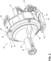
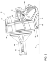
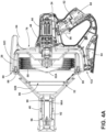
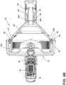
- FIGS. 1-4B illustrate a drain cleaner 20.
- the illustrated drain cleaner 20 includes a handle assembly 24, a shroud 28, a drum assembly 32, and a nose assembly 40.
- the shroud 28 may be a drum shield.
- the drain cleaner 20 also includes a motor 44 and a drive mechanism 48 positioned within the handle assembly 24.
- the drain cleaner 20 further includes a flexible cable 50 that is stored within the drum assembly 32 and extends out of the nose assembly 40.
- the cable 50 is insertable into a drain, or other conduit, for cleaning the drain.
- the cable 50 may include an auger head or other tool attachment at its distal end.
- the handle assembly 24 extends rearwardly from the shroud 28.
- the handle assembly 24 includes a grip 52 that is configured to be grasped by a user for carrying and operating the drain cleaner 20.
- the handle assembly 24 supports an actuator 56 (e.g., a trigger) adjacent the grip 52.
- the actuator 56 is actuatable (e.g., depressible) by a user to selectively energize the motor 44 and, thereby, operate the drain cleaner 20.
- the illustrated handle assembly 24 also includes a battery receptacle 60 for receiving and supporting a battery pack, such as a power tool battery pack.
- the battery receptacle 60 includes terminals that electrically connect the battery pack to the motor 44 and the actuator 56.
- the handle assembly 24 may support a power cord to electrically connect the motor 44 to an AC power source.
- the illustrated handle assembly 24 further includes a stand 64.
- the stand 64 is a base.
- the stand 64 is positioned generally beneath the shroud 28 and the motor 44. More particularly, the stand 64 is positioned beneath a center of gravity CG of the drain cleaner 20, which is principally defined by the motor 44, the drive mechanism 48, the cable 50, and the battery pack (if present) of the drain cleaner 20.
- the stand 64 includes a generally planar surface 68 that is configured to engage and rest on a support surface 72 (e.g., a table, a workbench, a countertop, the floor, etc.). In one embodiment, the stand 64 may provide ease of use during operation.
- the stand 64 supports the drain cleaner 20 in an upright position (as illustrated in FIG. 3 ) with the nose assembly 40 spaced apart from the support surface 72.
- the shroud 28 is coupled to the handle assembly 24 generally above the stand 64.
- the illustrated shroud 28 is generally cup-shaped and includes a closed end 76 adjacent or facing the handle assembly 24 and an open end 80 adjacent or facing the drum cover 32B.
- the shroud 28 is fixed to the handle assembly 24 such that the shroud 28 is stationary (i.e., does not rotate or otherwise move) relative to the handle assembly 24 during operation of the drain cleaner 20.
- the shroud 28 is positioned around the drum assembly 32 to help protect the drum assembly 32.
- the shroud 28 also inhibits the drum assembly 32 from contacting surrounding structures or surfaces, allowing the drain cleaner 20 to be used in relatively tight spaces without the drum assembly 32 contacting and potentially marring the surrounding structures or surfaces as it rotates.
- the shroud 28 protects a user from the spinning drum assembly 32, and provides ease of use if the user supports the drain cleaner 20 with his/her body during operation (e.g., rests the drain cleaner 20 on a knee or hip).
- the shroud 28 includes a carrying handle 84.
- the carrying handle 84 extends rearwardly from an upper side of the shroud 28 (i.e., from a side of the shroud 28 opposite the stand 64).
- the carrying handle 84 facilitates lifting and carrying the drain cleaner 20 when not in use.
- the handle 84 may be omitted.
- the drum assembly 32 is positioned substantially within the shroud 28.
- the illustrated drum assembly 32 includes an inner drum 32A, a drum cover 32B, and a drum support 32C.
- the inner drum 32A is configured to support the cable 50 of the drain cleaner 20.
- the inner drum 32A is positioned at least partially within the drum support 3C and includes an open forward end 86.
- the drum cover 32B extends over the open forward end 86 of the inner drum 32A.
- the drum cover 32B is also coupled to the drum support 32C.
- the drum cover 32B is coupled to the drum support 32C with threaded fasteners 88 (e.g., screws).
- the threaded fasteners 88 allow the drum cover 32B to be removed from the drum support 32C for replacing and/or cleaning the cable 50 and inside of the drum assembly 32.
- the drum cover 32B is secured to the drum support 32C, the inner drum 32A is captured or sandwiched between the drum cover 32B and the drum support 32C so that the entire drum assembly 32 moves (e.g., rotates) together.
- the drum cover 32B may be coupled to the drum support 32C with other suitable coupling means.
- the drum support 32C is coupled to the drive mechanism 48 such that rotation of the motor 44 is transmitted to the drum assembly 32 through the drive mechanism 48. Friction between the inner surface of the inner drum 32A and the cable 50 causes the cable 50 to rotate or spin with the drum assembly 32. As the drum assembly 32 rotates, the cable 50 also rotates, causing the cable 50 to be extended into the drain or retracted from the drain.
- the illustrated drive mechanism 48 includes a gear train having, for example, planetary gear arrangements and an output shaft that transmit rotation of the motor 44 to the drum support 32C.
- the drum support 32C is threadably coupled to the output shaft of the drive mechanism 48.
- the drum support 32C may be coupled to the drive mechanism 48 using other suitable means to transmit force (e.g., rotation) from the drive mechanism 48 to the drum assembly 32. Additionally, in some embodiments, other suitable drive mechanisms may also or alternatively be employed.
- the illustrated drum cover 32B includes an extended portion 92 that extends away from the drum assembly 32 and into the nose assembly 40.
- the extended portion 92 guides the cable 50 from the drum assembly 32 out of the drain cleaner 20.
- the nose assembly 40 is positioned forward of the shroud 28 and provides a second grip 96 for a user to hold the drain cleaner 20 during operation. For example, a user can grasp the grip 52 of the handle assembly 24 with one hand to operate the actuator 56, and can grasp the second grip 96 of the nose assembly 40 with the other hand to help guide the drain cleaner 20.
- the illustrated nose assembly 40 also provides a lock mechanism 98 for the drain cleaner 20.
- the nose assembly 40 is slidable toward and away from the drum assembly 32 to selectively lock and unlock the cable 50, respectively.
- the lock mechanism 98 includes two spring clips 98A positioned within the nose assembly 40 on opposite sides of the extended portion 92 of the drum cover 32B. When the nose assembly 40 is slid toward the drum assembly 32, the spring clips 98A are pushed inwardly to engage the cable 50. In this position, the cable 50 is forced to rotate with the drum assembly 32 since the spring clips 98A move with the extended portion 92 of the drum cover 32B.
- the spring clips 98A are biased apart from each other and disengage the cable 50 so that the cable 50 can be fed out of or into the drum assembly 32.
- the nose assembly 40 may be biased away from the drum assembly 32 (i.e., toward an unlocked position) by a spring or other biasing member.
- the illustrated nose assembly 40 slides axially between engaged and disengaged positions, in other embodiments, the nose assembly 40 may rotate between the engaged and disengaged positions.
- the drain cleaner 20 also includes a light 132.
- the illustrated light 132 is supported by the handle assembly 24 between the shroud 28 and the stand 64.
- the light 132 is also electrically coupled to the battery pack (or other power source of the drain cleaner 20) through the actuator 56.
- the actuator 56 When the actuator 56 is depressed by a user to rotate the drum assembly 32, the light 132 is also powered to illuminate an area in front of the drain cleaner 20.
- the light 132 may include a light emitting diode (LED) or LED array. In other embodiments, other suitable lights may be employed.
- FIG. 5 illustrates a storage container 100 for the drain cleaner 20.
- the illustrated storage container 100 includes a bucket 104 and an insert 108.
- the bucket 104 is, for example, a 0.0189m 3 (5-gallon) bucket having a bottom 112 and a generally cylindrical sidewall 116.
- the storage container 100 may include different sized and/or shaped open-topped containers.
- the bucket 104 may be a container having a rectangular-, oval-, or polygonal-shaped sidewall.
- the bucket 104 (or other container) may also include a handle for carrying the bucket 104.
- a lid may be selectively coupled to an upper edge of the sidewall 116 to enclose the bucket 104 (or other container).
- the bucket 104 is configured to receive the drain cleaner 20 for storing and/or transporting the drain cleaner 20.
- the bucket 104 may also be sold with the drain cleaner 20 as the carrying case for the drain cleaner 20.
- the storage bucket 104 may be designed to accommodate specific users to reduce mess and allow for storage and transport of a drain cleaner, as well as additional tools and/or accessories that may be used during a drain cleaning operation in conjunction with the drain cleaner (e.g., locking pliers, rags, etc.).
- the insert 108 is positionable inside the bucket 104 to help support the drain cleaner 20 within the bucket 104.
- the insert 108 includes a base 120 and a plurality of projections 124 extending upward from the base 120.
- the base 120 is planar, with a generally flat top surface and bottom surface. The flat bottom surface of the base 120 enables the base 120 to sit flat on the inside of the bucket 104.
- the base 120 has an outer perimeter that corresponds to an inner perimeter of the wall 116 of the bucket 104.
- the illustrated insert 108 includes a circular base 120 and four projections 124 extending perpendicularly from the base 120. In the illustrated embodiment, the circular base 120 and the projections 124 are integrally formed as a single piece of plastic.
- the insert 108 may include fewer or more projections 124, the base 120 and the projections 124 may be formed as separate pieces that are coupled together, and/or the insert 108 may be formed of other material(s).
- the circular base 120 generally corresponds to the shape and size of the bottom 112 of the bucket 104.
- the projections 124 are circumferentially spaced evenly around the circular base 120.
- the illustrated projections 124 are generally triangular in shape and taper in height from the center of the base 120 toward the outer perimeter of the base 120.
- the projections 124 are configured to engage the nose assembly 40 of the drain cleaner 20 to support the drain cleaner 20 above the bottom 112 of the bucket 104.
- a central gap 128 formed between the projections 124 at the center of the base 120 provides clearance for a cable of the drain cleaner 20 when the drain cleaner 20 is supported by the insert 108.
- this configuration may tend to prevent or deter damaging or bending of a cable tip while allowing the tool to rest upside-down in a bucket to allow draining of liquid or debris from the tool after use.
- the insert 108 is free floating within the bucket 104. This arrangement allows the insert 108 to be easily removed from the bucket 104 for cleaning.
- the insert 108 may be releasably secured to the bucket 104.
- the insert 108 may be permanently secured to the bottom 112 of the bucket 104, or the projections 124 of the insert 108 may be integrally formed in the bottom 112 of the bucket 104.
- the bucket 104 may be replaced with a different sized or shaped container, in which case the insert 108 may be correspondingly shaped and sized to fit within the container and support the drain cleaner 20 above the bottom of the container.
- FIG. 8 illustrates the drain cleaner 20 positioned within the bucket 104 for storage or sale.
- the insert 108 is positioned at the bottom 112 of the bucket 104 and contacts the nose assembly 40 of the drain cleaner 20 to support the drain cleaner 20 above the bottom 112 of the bucket 104.
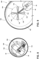
- FIG. 9 illustrates the storage container 100 with the drain cleaner 20 removed.
- the insert 108 is positioned at the bottom 112 of the bucket 104.
- a cable 136 extends from the nose assembly 40 of the drain cleaner 20.
- the insert 108 provides clearance for a distal end section 140 of the cable 136 so that the cable 136 is not unintentionally bent or otherwise deformed while the drain cleaner 20 is stored within the bucket 104.
- FIG. 10 illustrates the storage container 100 with a shroud or apron 144 (e.g., a bucket organizer wrap) coupled to the bucket 104.
- the apron 144 may be made of a fabric material, such as canvas. In another embodiment, the apron 144 is made from polyester or nylon. In other embodiments, other suitable materials may be used.
- the apron 144 wraps around the sidewall 116 of the bucket 104 and includes pockets 148 for storing items associated with the drain cleaner 20 (e.g., battery packs, cable attachments, brushes, etc.). In the illustrated embodiment, the apron 144 also includes a belt 152 that tightly engages the bucket 104 to suspend the apron 144 from the bucket 104.
- Ends of the belt 152 are secured together by a buckle 156 so that the apron 144 is removable from the bucket 104.
- the ends of the belt 152 may be secured together with loops, snaps, Velcro, or the like.
- the apron 144 may include hooks that extend over an upper edge of the bucket 104 to suspend the apron 144 from the bucket 104. In each of these embodiments, none of the apron 144 extends inside the bucket 104, which reduces the possibility of soiling the apron 144.
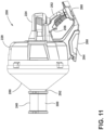
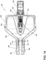
- FIGS. 11-14 illustrate another drain cleaner 200 that is similar to the drain cleaner 20 discussed above.
- the drain cleaner 200 includes a handle assembly 224, a shroud 228, a drum 232, and a nose assembly 240.
- the drain cleaner 200 also includes a motor 244 and a drive mechanism 248 positioned within the handle assembly 224.
- the drain cleaner 200 further includes a flexible cable (not shown) that is stored within the drum 232 and extends out of nose assembly 240. The cable is insertable into a drain, or other conduit, for cleaning the drain.
- the handle assembly 224 includes a grip 252 that is configured to be grasped by a user for carrying and operating the drain cleaner 200.
- the handle assembly 224 supports an actuator 256 (e.g., a trigger) adjacent the grip 252.
- the actuator 256 is actuatable by a user to selectively energize the motor 244 and, thereby, operate the drain cleaner 200.
- the illustrated handle assembly 224 also includes a battery receptacle 260 for receiving and supporting a battery pack.
- the handle assembly 224 further includes a stand 264.
- the stand 264 is positioned generally beneath the shroud 228 and the motor 244. More particularly, the stand 264 is positioned beneath a center of gravity of the drain cleaner 200, which is principally defined by the motor 244, the drive mechanism 248, the cable, and the battery pack (if present) of the drain cleaner 200.
- the stand 264 includes a generally planar surface 268 that is configured to engage and rest on a support surface. The stand 264 supports the drain cleaner 200 in an upright position with the nose assembly 240 spaced apart from the support surface.
- the shroud 228 is coupled to the handle assembly 224 generally above the stand 264.
- the illustrated shroud 228 is generally cup-shaped and includes a closed end 276 adjacent or facing the handle assembly 224.
- the shroud 228 is fixed to the handle assembly 224 such that the shroud 228 is stationary (i.e., does not rotate or otherwise move) relative to the handle assembly 224 during operation of the drain cleaner 200.
- the shroud 228 is positioned around the drum 232 to help protect the drum 232.
- the shroud 228 allows the drain cleaner 200 to be used in relatively tight spaces without the drum contacting surrounding structures.
- the shroud 228 also protects a user from the spinning drum assembly 232.
- the drum 232 is positioned substantially within the shroud 228.
- the drum 232 is rotatably driven by the motor 244, which in turn, rotates the cable.
- the drum 232 rotates within and relative to the shroud 228.
- the motor 244 and the drive mechanism 248 are nested within a cavity 242 formed within the center of the drum 232.
- the cable is coiled around the outside of the cavity 242 while the motor 244 and drive mechanism 248 engage with the drum 232 from the inside of the cavity 242.
- the illustrated drain cleaner 200 further includes an outer shield 280.
- the outer shield 280 is fixed to a shroud 228 of the drain cleaner 200 to completely enclose the drum 232.
- a seal 246 is formed between the shroud 228 and the shield 280 to seal in water.
- the seal 246 can be formed by an elastomer, plastic, or any other known material capable of forming a water tight connection between the shroud 228 and the shield 280.
- the outer shield 280 also forms part of the nose assembly 240 of the illustrated drain cleaner 200. By completely enclosing the rotating drum 232, the outer shield 280 facilitates working in enclosed spaces and inhibits inadvertent contact between the drum 232 and any fixtures, cabinets, or other nearby surfaces.
- the nose assembly 240 includes an elongated portion 292 that guides the cable into the drain.
- the elongated portion 292 of the nose assembly 240 is formed by the outer shield 280.
- the outer shield 280 and the elongated portion 292 are formed as a continuous element.
- the nose assembly 240 is a separate element from the outer shield 280.
- the illustrated drain cleaner 200 also includes a cable lock mechanism 300.
- the illustrated cable lock mechanism 300 is at least partially supported by the outer shield 280.
- the cable lock mechanism 300 is slidable along a portion of the nose assembly 240 between an unclamped position ( FIGS. 12 and 13 ) and a clamped position ( FIG. 14 ).
- the cable lock mechanism 300 includes a cam member 310 that is configured to engage spring clips 314 within the nose assembly 240.
- the spring clips 314 can selectively clamp the cable to limit or allow axial movement of the cable.
- the cable lock mechanism 300 In the unclamped position, the cable lock mechanism 300 is slid forward along the outer shield 280 (i.e., away from a motor and drive mechanism 300 of the drain cleaner 200). In this position, the cam member 310 is not engaged with the spring clips 314. Accordingly, the spring clips 314 are in a neutral, unbiased position and are not engaged with the cable. Therefore, the cable is free to move.
- the cable lock mechanism 300 In the clamped position, the cable lock mechanism 300 is slid rearward along the outer shield 280 (i.e., toward the motor and drive mechanism 300 of the drain cleaner 200). Sliding the cable lock mechanism 300 in the rearward direction forces the cam members 310 to engage the spring clips 314, which biases the spring clips 314 radially inward. In this position, the spring clips 314 of the cable lock mechanism 300 are forced inward to engage the cable so the cable is clamped. In some embodiments, the cable lock mechanism 300 may be biased toward the unclamped position.
Landscapes
- Engineering & Computer Science (AREA)
- Health & Medical Sciences (AREA)
- Life Sciences & Earth Sciences (AREA)
- Hydrology & Water Resources (AREA)
- Public Health (AREA)
- Water Supply & Treatment (AREA)
- Mechanical Engineering (AREA)
- Environmental & Geological Engineering (AREA)
- Electric Vacuum Cleaner (AREA)
- Storing, Repeated Paying-Out, And Re-Storing Of Elongated Articles (AREA)
- Sink And Installation For Waste Water (AREA)
Claims (13)
- Nettoyeur de canalisation d'évacuation comprenant :un ensemble poignée (24) comportant un élément de préhension (52) ;un moteur (44) positionné au sein de l'ensemble poignée ;un actionneur (56) supporté par l'ensemble poignée, adjacent à l'élément de préhension, l'actionneur couplé électriquement au moteur et fonctionnel pour alimenter sélectivement le moteur ;une enveloppe (28) fixée à et s'étendant vers l'avant à partir de l'ensemble poignée, l'enveloppe comportant une extrémité fermée (76) adjacente à l'ensemble poignée ;un ensemble tambour (32) accouplé de manière rotative à l'ensemble poignée et positionné au sein de l'enveloppe, l'ensemble tambour fonctionnel pour être mis en rotation par le moteur par rapport à l'ensemble poignée et à l'enveloppe ;un câble flexible (50) stocké au sein de l'ensemble tambour, le câble flexible conçu pour être étendu à l'extérieur de l'ensemble tambour et dans une canalisation d'évacuation ; etun mécanisme d'entraînement (48) positionné au sein de l'ensemble poignée et accouplé au moteur,dans lequel l'ensemble tambour comporte un tambour interne (32A) supportant le câble flexible et un support de tambour (32C) positionné autour du tambour interne, dans lequel le mécanisme d'entraînement est accouplé au support de tambour pour transmettre une rotation du moteur à l'ensemble tambour ;dans lequel le tambour interne comporte une extrémité avant ouverte (86), et dans lequel l'ensemble tambour comporte en outre un couvercle de tambour (32B) accouplé au support de tambour et s'étendant par-dessus l'extrémité avant ouverte du tambour interne ; etdans lequel le nettoyeur de canalisation d'évacuation comprend en outre un ensemble nez (40) positionné vers l'avant de l'enveloppe (28), dans lequel une partie de l'ensemble tambour (32) s'étend dans l'ensemble nez, et dans lequel l'ensemble nez fournit un second élément de préhension (96) ;dans lequel l'ensemble nez (40) comporte un mécanisme de verrouillage (98) et peut coulisser en direction et à l'écart de l'ensemble tambour (32) pour verrouiller et déverrouiller sélectivement le câble flexible (50),dans lequel l'ensemble poignée (24) comporte un pied (64) positionné en dessous d'un centre de gravité (CG) du nettoyeur de canalisation d'évacuation ;dans lequel le pied (64) comporte une surface généralement plane (68) qui est configurée pour venir en prise avec et reposer sur une surface de support (72) ; etdans lequel le pied (64) supporte le nettoyeur de canalisation d'évacuation (20) dans une position dressée avec l'ensemble nez (40) espacé de la surface de support (72).
- Nettoyeur de canalisation d'évacuation selon la revendication 1, dans lequel l'enveloppe (28) est cupuliforme et comporte l'extrémité fermée (76) orientée face à l'ensemble poignée (24) et une extrémité ouverte (80) orientée à l'écart de l'ensemble poignée.
- Nettoyeur de canalisation d'évacuation selon la revendication 2, dans lequel une partie de l'ensemble tambour (32) est exposée au niveau de l'extrémité ouverte (80) de l'enveloppe (28).
- Nettoyeur de canalisation d'évacuation selon la revendication 2, dans lequel le nettoyeur de canalisation d'évacuation comprend en outre une protection externe fixée à l'enveloppe (28) au niveau de l'extrémité ouverte (80), dans lequel l'enveloppe et la protection externe enferment complètement le tambour.
- Nettoyeur de canalisation d'évacuation selon la revendication 1, dans lequel le couvercle de tambour (32B) est accouplé au support de tambour (32C) avec des fixations filetées (88).
- Nettoyeur de canalisation d'évacuation selon la revendication 1, dans lequel la surface généralement plane (68) s'étend en dessous du moteur (44) et de l'enveloppe (28).
- Nettoyeur de canalisation d'évacuation selon la revendication 6, dans lequel le nettoyeur de canalisation d'évacuation comprend en outre une lampe (32) supportée par l'ensemble poignée (24) entre l'enveloppe (28) et le pied (64), dans lequel la lampe est couplée électriquement à l'actionneur (56) de telle sorte que l'actionneur est fonctionnel pour alimenter sélectivement la lampe.
- Nettoyeur de canalisation d'évacuation selon la revendication 1, dans lequel l'enveloppe (28) comporte une poignée de transport (84) s'étendant à partir de la surface supérieure de l'enveloppe en direction de l'ensemble poignée (24).
- Nettoyeur de canalisation d'évacuation selon la revendication 1, dans lequel l'ensemble poignée (24) comporte un réceptacle de batterie (60) conçu pour recevoir un bloc-batterie.
- Système comprenant le nettoyeur de canalisation d'évacuation selon la revendication 1 et comprenant en outre :un contenant de stockage (100) comportantun seau (104) qui reçoit le nettoyeur de canalisation d'évacuation, le seau comportant un fond (112) et une paroi latérale (116) s'étendant vers le haut à partir du fond, la paroi latérale définissant un périmètre interne, etun insert (108) positionné au sein du seau, l'insert comportantune base (120) disposée sur le fond du seau, la base comportant un périmètre externe qui est dimensionné et profilé pour correspondre au périmètre interne de la paroi latérale du seau, etune pluralité de saillies (124) s'étendant vers le haut à partir de la base, la pluralité de saillies venant en prise avec une partie du nettoyeur de canalisation d'évacuation pour soutenir le nettoyeur de canalisation d'évacuation au-dessus du fond du seau.
- Système selon la revendication 10, dans lequel la paroi latérale (116) du seau (104) est généralement cylindrique, dans lequel la base (120) de l'insert (108) est circulaire, et dans lequel la pluralité de saillies (124) sont espacées circonférentiellement de manière uniforme autour de la base.
- Système selon la revendication 11, dans lequel chaque saillie (124) de l'insert (108) s'effile en hauteur à partir d'un centre de la base (120) jusqu'au périmètre externe de la base ; facultativement dans lequel la pluralité de saillies de l'insert sont espacées pour définir un espace central au niveau du centre de la base, et dans lequel l'espace central fournit un dégagement pour le câble flexible (50) du nettoyeur de canalisation d'évacuation.
- Système selon la revendication 12, dans lequel le contenant de stockage comporte en outre un manchon (144) enveloppé autour de la paroi latérale (116) du seau (104), dans lequel le manchon a des poches conçues pour stocker des articles associés au nettoyeur de canalisation d'évacuation.
Applications Claiming Priority (3)
| Application Number | Priority Date | Filing Date | Title |
|---|---|---|---|
| US201562264916P | 2015-12-09 | 2015-12-09 | |
| US201662296453P | 2016-02-17 | 2016-02-17 | |
| PCT/US2016/065942 WO2017100653A1 (fr) | 2015-12-09 | 2016-12-09 | Dégorgeoir |
Publications (3)
| Publication Number | Publication Date |
|---|---|
| EP3387194A1 EP3387194A1 (fr) | 2018-10-17 |
| EP3387194A4 EP3387194A4 (fr) | 2019-11-13 |
| EP3387194B1 true EP3387194B1 (fr) | 2024-05-29 |
Family
ID=59013641
Family Applications (1)
| Application Number | Title | Priority Date | Filing Date |
|---|---|---|---|
| EP16873970.4A Active EP3387194B1 (fr) | 2015-12-09 | 2016-12-09 | Dégorgeoir |
Country Status (4)
| Country | Link |
|---|---|
| US (5) | US9884353B2 (fr) |
| EP (1) | EP3387194B1 (fr) |
| CN (2) | CN113026928A (fr) |
| WO (1) | WO2017100653A1 (fr) |
Families Citing this family (20)
| Publication number | Priority date | Publication date | Assignee | Title |
|---|---|---|---|---|
| EP3387194B1 (fr) | 2015-12-09 | 2024-05-29 | Milwaukee Electric Tool Corporation | Dégorgeoir |
| US10626593B2 (en) * | 2016-04-05 | 2020-04-21 | Black & Decker Inc. | Powered drain auger |
| USD830806S1 (en) * | 2017-02-15 | 2018-10-16 | Black & Decker Inc. | Drain auger |
| CN116022606A (zh) * | 2017-12-14 | 2023-04-28 | 里奇工具公司 | 用于清洁使用、存储和运输的分段式下水道清洁线缆系统 |
| EP3849718B1 (fr) * | 2018-09-11 | 2025-03-19 | Milwaukee Electric Tool Corporation | Déboucheur |
| WO2020231966A1 (fr) | 2019-05-15 | 2020-11-19 | Milwaukee Electric Tool Corporation | Dispositif de nettoyage de drains |
| CN218555047U (zh) * | 2020-02-12 | 2023-03-03 | 米沃奇电动工具公司 | 排水管清洁机器 |
| EP4257760A4 (fr) * | 2021-01-08 | 2024-06-05 | Nanjing Chervon Industry Co., Ltd. | Machine de nettoyage de tuyau |
| US11298238B1 (en) * | 2021-07-23 | 2022-04-12 | Focus Medical Company, Llc | Balloon kyphoplasty surgical device and method |
| WO2023059852A1 (fr) * | 2021-10-07 | 2023-04-13 | Milwaukee Electric Tool Corporation | Machine de nettoyage de canalisation |
| DE112022003878T5 (de) | 2021-10-18 | 2024-07-18 | Milwaukee Electric Tool Corporation | Abflussreinigerwerkzeug |
| CA3181586A1 (fr) * | 2021-11-12 | 2023-05-12 | Techtronic Cordless Gp | Furet |
| US20230151600A1 (en) * | 2021-11-15 | 2023-05-18 | Emerson Professional Tools, LLC. | Sheathed flexible shaft drain cleaner |
| US20230398585A1 (en) * | 2022-06-08 | 2023-12-14 | Milwaukee Electric Tool Corporation | Closet auger |
| WO2024222486A1 (fr) * | 2023-04-28 | 2024-10-31 | 南京泉峰科技有限公司 | Dispositif de nettoyage de tuyau |
| US20250100028A1 (en) * | 2023-09-21 | 2025-03-27 | Techtronic Cordless Gp | Drain cleaner |
| US20250326011A1 (en) * | 2024-04-22 | 2025-10-23 | Emerson Professional Tool, LLC | Drain cleaners with a top-mounted light assembly |
| WO2025222320A1 (fr) * | 2024-04-22 | 2025-10-30 | Emerson Professional Tools, Llc | Dispositif de nettoyage de drains ayant une poignée pouvant tourner |
| WO2025222319A1 (fr) * | 2024-04-22 | 2025-10-30 | Emerson Professional Tools, Llc | Nettoyeurs de drains à liaison dentée entre le tambour et l'ensemble nez |
| WO2025222321A1 (fr) * | 2024-04-22 | 2025-10-30 | Emerson Professional Tools, Llc | Dispositifs de nettoyage de drain présentant un manchon de verrouillage de câble coulissant axialement |
Citations (2)
| Publication number | Priority date | Publication date | Assignee | Title |
|---|---|---|---|---|
| US4956889A (en) * | 1989-07-03 | 1990-09-18 | Emerson Electric Co. | Portable drain cleaning apparatus |
| US20080148503A1 (en) * | 2006-12-21 | 2008-06-26 | Emerson Electric Co. | Cable feeding device with indicator |
Family Cites Families (99)
| Publication number | Priority date | Publication date | Assignee | Title |
|---|---|---|---|---|
| US2244735A (en) | 1938-06-04 | 1941-06-10 | Silverman Abe | Pipe cleaning tool |
| US2223005A (en) | 1938-09-02 | 1940-11-26 | Frank J Kerber | Sewer cleaning device |
| US2297755A (en) | 1940-08-01 | 1942-10-06 | Conrad W Faust | Portable electric drain-pipe cleaner |
| US2625699A (en) * | 1949-12-16 | 1953-01-20 | Elsie M Jurasevich | Power-driven sewer cleaner |
| US2685097A (en) | 1951-05-28 | 1954-08-03 | George W Allen | Cable winding apparatus |
| US2849870A (en) | 1957-03-20 | 1958-09-02 | Silverman Abraham | Pipe cleaning tool |
| US3093854A (en) | 1960-06-13 | 1963-06-18 | Silverman Abraham | Machine for automatically feeding a plumber's snake |
| US3078486A (en) | 1961-11-09 | 1963-02-26 | Alvin G Casto | Plumber's snake meter |
| US3268937A (en) * | 1964-06-01 | 1966-08-30 | Burton J Bollinger | Power driven plumber snake |
| US3246354A (en) | 1964-07-23 | 1966-04-19 | Gen Wire Spring Company | Sewer augering machine with automatic feed mechanism and interchangeable drum means |
| US3414926A (en) | 1966-08-19 | 1968-12-10 | Bloom Meyer | Pipe cleaner |
| US3460501A (en) | 1967-01-03 | 1969-08-12 | Pan American Petroleum Corp | Stabilizing a floating vessel |
| US3480983A (en) | 1969-01-29 | 1969-12-02 | Charles B Caperton | Drive for rodding machine |
| US3574878A (en) | 1969-05-19 | 1971-04-13 | Melard Mfg Corp | Power rooter with safety clutch |
| US3662421A (en) | 1970-09-25 | 1972-05-16 | Charles B Caperton | Drive for rodding machine |
| US3691583A (en) * | 1971-01-06 | 1972-09-19 | Gen Wire Spring Co | Sewer augering machine |
| US4104757A (en) | 1976-08-02 | 1978-08-08 | Silverman Arthur A | Power driven drain cleaner with safety overload clutch |
| US4218802A (en) * | 1979-03-14 | 1980-08-26 | Emerson Electric Co. | Drain cleaning apparatus |
| US4290162A (en) * | 1979-07-10 | 1981-09-22 | Michael Agostino | Light-weight floor-standing drain cleaner |
| US4317247A (en) * | 1980-03-03 | 1982-03-02 | Levine Aaron J | Drive attachment for a drain cleaning plumbing tool |
| US4364139A (en) | 1981-05-07 | 1982-12-21 | Emerson Electric Co. | Drum type sewer cleaner |
| USD271436S (en) | 1981-06-26 | 1983-11-15 | Emerson Electric Co. | Sewer cleaning machine |
| USD287178S (en) | 1984-03-23 | 1986-12-09 | Emerson Electric Co. | Cart for a drain cleaning machine |
| US4617693A (en) * | 1984-08-06 | 1986-10-21 | Meyer Marjorie A | Drain pipe cleaning tool |
| US4734951A (en) | 1986-09-05 | 1988-04-05 | Sewer Rodding Equipment Company | Automated sewer cleaning rodding machine |
| USD307202S (en) | 1986-10-27 | 1990-04-10 | Cobra Products, Inc. | Tape housing for pipe cleaning |
| USD310280S (en) | 1986-12-04 | 1990-08-28 | Cobra Products, Inc. | Tape housing for pipe cleaning |
| US4925214A (en) | 1987-06-09 | 1990-05-15 | Hewlett-Packard Company | Count down system for recording charts |
| US4763374A (en) * | 1987-12-07 | 1988-08-16 | Lewisan Products, Inc. | Powered drain cleaner |
| US4793017A (en) * | 1987-12-07 | 1988-12-27 | Lewisan Products, Inc. | Vibrating drain-cleaning implement |
| US4914775A (en) | 1988-12-19 | 1990-04-10 | Emerson Electric Co. | Retainer mechanism for drain cleaner drum |
| US5009242A (en) | 1989-09-12 | 1991-04-23 | Sewer Rodding Equipment Company | Apparatus for monitoring sewer cleaning tool extension |
| EP0513166A4 (en) | 1990-01-30 | 1993-02-24 | Rosemount Inc. | Preassembled air data sensor and transducer |
| US5031263A (en) | 1990-02-20 | 1991-07-16 | Emerson Electric Co. | Drain cleaning machine |
| US5031276A (en) | 1990-02-20 | 1991-07-16 | Emerson Electric Co. | Drain cleaning machine |
| US5365874A (en) | 1992-12-18 | 1994-11-22 | Dorfman Jason R | End of dental floss tape indicator |
| US5419349A (en) | 1993-02-09 | 1995-05-30 | Emerson Electric Co. | Portable small parts washer |
| US5390389A (en) | 1994-05-16 | 1995-02-21 | Emerson Electric Company | Wheeled load carrier |
| US5622319A (en) | 1995-03-03 | 1997-04-22 | Emerson Electric Company | Portable water jetter apparatus |
| US5661265A (en) | 1995-12-11 | 1997-08-26 | Appleton Electric Company | Drain for electrical enclosure |
| US5657505A (en) | 1996-01-29 | 1997-08-19 | Emerson Electric Company | Drain cleaning apparatus |
| US5816165A (en) | 1997-02-10 | 1998-10-06 | Hewlett-Packard Company | Method of encoding roll length indicia on printer media |
| US5901401A (en) | 1997-07-28 | 1999-05-11 | Emerson Electric Company | Feed control device for plumbing tools |
| US5924566A (en) * | 1997-10-08 | 1999-07-20 | Gibbs; Paul Stephen | Plunger caddy |
| US6009588A (en) | 1998-07-16 | 2000-01-04 | Emerson Electric Co. | Drain cleaning apparatus |
| US6158076A (en) | 1999-02-22 | 2000-12-12 | Emerson Electric Co. | Feed control devices for hand operated drain cleaning tools |
| US6467612B1 (en) | 1999-05-24 | 2002-10-22 | David Rosenfeld | Suture reel dispenser with end of suture indicator |
| US6470525B1 (en) | 1999-11-30 | 2002-10-29 | Arthur A. Silverman | Drain cleaning apparatus having remote power feed |
| US6381798B1 (en) | 1999-12-23 | 2002-05-07 | Emerson Electric Co. | Spring clutch for drain cleaning machines |
| US6343398B1 (en) | 2000-04-13 | 2002-02-05 | General Wire Spring Company | Drain cleaning apparatus with feed control |
| US6360397B1 (en) | 2000-05-17 | 2002-03-26 | Emerson Electric Co. | Feed control device for plumbing apparatus |
| US6615436B1 (en) | 2000-09-11 | 2003-09-09 | Emerson Electric Co. | Powered drain cleaner |
| US6637064B2 (en) | 2001-01-02 | 2003-10-28 | Lee H. Silverman | Drain cleaning apparatus with remotely adjustable feed control |
| US6546582B2 (en) | 2001-06-18 | 2003-04-15 | Lee H. Silverman | Drain cleaning machine and adjustable collet chuck mechanism therefor |
| US6618891B2 (en) | 2001-08-10 | 2003-09-16 | Masco Corporation | Rotary drum release for a drain cleaning machine |
| US6760948B2 (en) | 2001-08-16 | 2004-07-13 | Masco Corporation | Snap latch drum release for a drain cleaning machine |
| US6618892B2 (en) | 2001-09-27 | 2003-09-16 | Masco Corporation | Socket latch drum release for a drain cleaning machine |
| US6898881B2 (en) | 2002-05-29 | 2005-05-31 | Jane Morrison | Product quantity indicator tab |
| US7073224B2 (en) | 2002-06-18 | 2006-07-11 | Masco Corporation | Telescopic polygon radial drive coupling for a drain cleaning machine |
| US7117052B2 (en) | 2003-02-18 | 2006-10-03 | Fisher-Rosemount Systems, Inc. | Version control for objects in a process plant configuration system |
| US7676879B1 (en) | 2003-07-22 | 2010-03-16 | Rutenberg Keith H | Battery-powered sewer and drain cleaner |
| CN2642855Y (zh) * | 2003-09-13 | 2004-09-22 | 张卿 | 有线遥控智能污水管道疏通清理器 |
| US7185759B2 (en) * | 2004-02-09 | 2007-03-06 | Waxman Consumer Products Group Inc. | Rotating toilet tool holder |
| US7478451B2 (en) | 2004-03-04 | 2009-01-20 | Emerson Electric Co. | Feed control device for plumbing tools |
| US7685669B2 (en) | 2004-03-04 | 2010-03-30 | Emerson Electric Co. | Feed control device for plumbing tools |
| US7367077B2 (en) | 2004-03-04 | 2008-05-06 | Emerson Electric Co. | Drain cleaning apparatus |
| US7137503B2 (en) | 2004-03-12 | 2006-11-21 | Emerson Electric Co. | Auger brush |
| USD509929S1 (en) | 2004-08-10 | 2005-09-20 | Emerson Electric Co. | Drain cleaner |
| US7793608B1 (en) | 2005-01-06 | 2010-09-14 | Udouj John C | Reserve sheet material roll with low supply indicator |
| US7269874B2 (en) * | 2005-03-04 | 2007-09-18 | Yoen Hung | Cleaning device for cleaning ducts and pipes |
| WO2006112848A1 (fr) | 2005-04-14 | 2006-10-26 | Emerson Electric Co. | Dispositif de contrôle d'alimentation d'outils de plomberie |
| CN101180139A (zh) * | 2005-04-14 | 2008-05-14 | 艾默生电气公司 | 排水管清洗设备 |
| CA2604221A1 (fr) | 2005-04-14 | 2006-10-26 | Emerson Electric Co. | Dispositif de nettoyage de conduites |
| US20080098544A1 (en) | 2006-10-30 | 2008-05-01 | Emerson Electric Co. | Drain cleaning machine with added stability, portability and maneuverability |
| US20080244816A1 (en) | 2007-04-03 | 2008-10-09 | Emerson Electric Co. | Closet auger |
| USD579612S1 (en) | 2007-04-26 | 2008-10-28 | Emerson Electric Co. | Frame for a drain cleaning machine |
| CA2702893C (fr) | 2007-10-15 | 2016-04-12 | Micro Motion, Inc. | Debitmetre vibrant et procede permettant de determiner une temperature de fluide d'une substance en ecoulement |
| US8899554B2 (en) | 2007-12-19 | 2014-12-02 | Klein Tools, Inc. | Reverse marked fish tape |
| US8578949B2 (en) | 2008-01-31 | 2013-11-12 | Sunstar Americas, Inc. | Multi-texture floss and methods of manufacturing multi-texture floss |
| US8662092B2 (en) | 2008-01-31 | 2014-03-04 | Sunstar Americas, Inc. | Dispenser for multi-texture floss |
| USD582108S1 (en) | 2008-03-04 | 2008-12-02 | Emerson Electric Co. | Hand held drain cleaning apparatus |
| US8046862B2 (en) | 2008-08-08 | 2011-11-01 | Emerson Electric Co. | Drain cleaning apparatus with electronic cable counter |
| EP2313211B1 (fr) | 2008-05-22 | 2015-09-30 | Emerson Electric Co. | Appareil de nettoyage de drain, methode de determination de longueur de câble et systeme electronique de surveillance du câble. |
| US8176593B2 (en) | 2008-05-22 | 2012-05-15 | Emerson Electric Co. | Drain cleaning apparatus with electronic cable monitoring system |
| US8060968B2 (en) | 2008-08-28 | 2011-11-22 | Emerson Electric Co. | Variable belt tensioner for drain cleaning devices |
| US7806256B2 (en) | 2008-10-02 | 2010-10-05 | Cobra Products, Inc. | Plunger caddy assembly |
| US7889980B2 (en) * | 2008-11-21 | 2011-02-15 | Emerson Electric Co. | Graphical representation of enclosed inspection area |
| US20100127922A1 (en) | 2008-11-21 | 2010-05-27 | Emerson Electric Co. | System for sharing video captured at jobsite |
| US7935192B2 (en) | 2008-12-08 | 2011-05-03 | General Wire Spring Co. | Drain cleaning apparatus with restricted reverse function |
| US8539618B2 (en) | 2009-07-30 | 2013-09-24 | Masco Canada Limited | Drain cover for sinks |
| US20110182656A1 (en) | 2010-01-27 | 2011-07-28 | Emerson Electric Co. | Sleeved coupling |
| US8434186B2 (en) | 2010-02-10 | 2013-05-07 | Cobra Products, Inc. | Drum auger |
| DE102012112599A1 (de) * | 2011-12-21 | 2013-06-27 | Emerson Electric Co. | Vorschubsteuersperre für manuell bedienten Abflussreiniger |
| US8826483B2 (en) | 2011-12-21 | 2014-09-09 | Emerson Electric Co. | Feed control lock for hand operated drain cleaner |
| US9260847B2 (en) | 2013-02-13 | 2016-02-16 | General Wire Spring Company | Ball type clamp assembly |
| US9234342B1 (en) * | 2014-09-16 | 2016-01-12 | Daniel Joseph Beesley | Handheld powered cable-drum drain cleaning machine |
| CN204510460U (zh) * | 2015-01-28 | 2015-07-29 | 宁德师范学院 | 一种水沟疏通器 |
| EP3387194B1 (fr) | 2015-12-09 | 2024-05-29 | Milwaukee Electric Tool Corporation | Dégorgeoir |
| US10626593B2 (en) | 2016-04-05 | 2020-04-21 | Black & Decker Inc. | Powered drain auger |
-
2016
- 2016-12-09 EP EP16873970.4A patent/EP3387194B1/fr active Active
- 2016-12-09 WO PCT/US2016/065942 patent/WO2017100653A1/fr not_active Ceased
- 2016-12-09 CN CN202110314916.4A patent/CN113026928A/zh active Pending
- 2016-12-09 CN CN201680072311.6A patent/CN108368699B/zh active Active
-
2017
- 2017-02-07 US US15/426,762 patent/US9884353B2/en active Active
-
2018
- 2018-01-04 US US15/862,360 patent/US9975154B1/en active Active
- 2018-04-16 US US15/953,643 patent/US10239100B2/en active Active
-
2019
- 2019-03-05 US US16/292,913 patent/US11103902B2/en active Active
-
2021
- 2021-07-22 US US17/382,728 patent/US11684957B2/en active Active
Patent Citations (2)
| Publication number | Priority date | Publication date | Assignee | Title |
|---|---|---|---|---|
| US4956889A (en) * | 1989-07-03 | 1990-09-18 | Emerson Electric Co. | Portable drain cleaning apparatus |
| US20080148503A1 (en) * | 2006-12-21 | 2008-06-26 | Emerson Electric Co. | Cable feeding device with indicator |
Also Published As
| Publication number | Publication date |
|---|---|
| US20190193128A1 (en) | 2019-06-27 |
| US20180126429A1 (en) | 2018-05-10 |
| CN108368699A (zh) | 2018-08-03 |
| US20210346921A1 (en) | 2021-11-11 |
| EP3387194A4 (fr) | 2019-11-13 |
| WO2017100653A1 (fr) | 2017-06-15 |
| US9884353B2 (en) | 2018-02-06 |
| EP3387194A1 (fr) | 2018-10-17 |
| US20170165723A1 (en) | 2017-06-15 |
| US11103902B2 (en) | 2021-08-31 |
| US9975154B1 (en) | 2018-05-22 |
| US11684957B2 (en) | 2023-06-27 |
| US10239100B2 (en) | 2019-03-26 |
| CN113026928A (zh) | 2021-06-25 |
| US20180229279A1 (en) | 2018-08-16 |
| CN108368699B (zh) | 2021-04-13 |
Similar Documents
| Publication | Publication Date | Title |
|---|---|---|
| US11684957B2 (en) | Drain cleaner | |
| US12336681B2 (en) | Hand-held surface cleaning device | |
| US9234342B1 (en) | Handheld powered cable-drum drain cleaning machine | |
| CN107663886B (zh) | 用于排水管清洁器的缆绳进给控制机构 | |
| US10646905B2 (en) | Modular guide hose system for plumbing tools | |
| CA2999068A1 (fr) | Un appareil de nettoyage par aspiration | |
| EP4528042A2 (fr) | Dispositif de nettoyage de drain |
Legal Events
| Date | Code | Title | Description |
|---|---|---|---|
| STAA | Information on the status of an ep patent application or granted ep patent |
Free format text: STATUS: THE INTERNATIONAL PUBLICATION HAS BEEN MADE |
|
| PUAI | Public reference made under article 153(3) epc to a published international application that has entered the european phase |
Free format text: ORIGINAL CODE: 0009012 |
|
| STAA | Information on the status of an ep patent application or granted ep patent |
Free format text: STATUS: REQUEST FOR EXAMINATION WAS MADE |
|
| 17P | Request for examination filed |
Effective date: 20180704 |
|
| AK | Designated contracting states |
Kind code of ref document: A1 Designated state(s): AL AT BE BG CH CY CZ DE DK EE ES FI FR GB GR HR HU IE IS IT LI LT LU LV MC MK MT NL NO PL PT RO RS SE SI SK SM TR |
|
| AX | Request for extension of the european patent |
Extension state: BA ME |
|
| DAV | Request for validation of the european patent (deleted) | ||
| DAX | Request for extension of the european patent (deleted) | ||
| RIC1 | Information provided on ipc code assigned before grant |
Ipc: E03F 9/00 20060101AFI20190702BHEP Ipc: B65H 75/36 20060101ALI20190702BHEP Ipc: B08B 9/045 20060101ALI20190702BHEP |
|
| A4 | Supplementary search report drawn up and despatched |
Effective date: 20191014 |
|
| RIC1 | Information provided on ipc code assigned before grant |
Ipc: B65H 75/36 20060101ALI20191008BHEP Ipc: B08B 9/045 20060101ALI20191008BHEP Ipc: E03F 9/00 20060101AFI20191008BHEP |
|
| STAA | Information on the status of an ep patent application or granted ep patent |
Free format text: STATUS: EXAMINATION IS IN PROGRESS |
|
| 17Q | First examination report despatched |
Effective date: 20210628 |
|
| GRAP | Despatch of communication of intention to grant a patent |
Free format text: ORIGINAL CODE: EPIDOSNIGR1 |
|
| STAA | Information on the status of an ep patent application or granted ep patent |
Free format text: STATUS: GRANT OF PATENT IS INTENDED |
|
| INTG | Intention to grant announced |
Effective date: 20240103 |
|
| GRAS | Grant fee paid |
Free format text: ORIGINAL CODE: EPIDOSNIGR3 |
|
| GRAA | (expected) grant |
Free format text: ORIGINAL CODE: 0009210 |
|
| STAA | Information on the status of an ep patent application or granted ep patent |
Free format text: STATUS: THE PATENT HAS BEEN GRANTED |
|
| RIN1 | Information on inventor provided before grant (corrected) |
Inventor name: MILLER, JUSTIN Inventor name: DENISSEN, RYAN JAMES Inventor name: KEHOE, SEAN T. Inventor name: CORBAT, JEFFREY Inventor name: BEIERLE, JACQUELINE J. Inventor name: GAINACOPULOS, NIKOS A. Inventor name: MO, CELENE K. Inventor name: BANHOLZER, HANS T. |
|
| AK | Designated contracting states |
Kind code of ref document: B1 Designated state(s): AL AT BE BG CH CY CZ DE DK EE ES FI FR GB GR HR HU IE IS IT LI LT LU LV MC MK MT NL NO PL PT RO RS SE SI SK SM TR |
|
| REG | Reference to a national code |
Ref country code: CH Ref legal event code: EP |
|
| REG | Reference to a national code |
Ref country code: IE Ref legal event code: FG4D |
|
| REG | Reference to a national code |
Ref country code: DE Ref legal event code: R096 Ref document number: 602016087776 Country of ref document: DE |
|
| REG | Reference to a national code |
Ref country code: LT Ref legal event code: MG9D |
|
| REG | Reference to a national code |
Ref country code: NL Ref legal event code: MP Effective date: 20240529 |
|
| PG25 | Lapsed in a contracting state [announced via postgrant information from national office to epo] |
Ref country code: IS Free format text: LAPSE BECAUSE OF FAILURE TO SUBMIT A TRANSLATION OF THE DESCRIPTION OR TO PAY THE FEE WITHIN THE PRESCRIBED TIME-LIMIT Effective date: 20240929 |
|
| PG25 | Lapsed in a contracting state [announced via postgrant information from national office to epo] |
Ref country code: BG Free format text: LAPSE BECAUSE OF FAILURE TO SUBMIT A TRANSLATION OF THE DESCRIPTION OR TO PAY THE FEE WITHIN THE PRESCRIBED TIME-LIMIT Effective date: 20240529 |
|
| PG25 | Lapsed in a contracting state [announced via postgrant information from national office to epo] |
Ref country code: HR Free format text: LAPSE BECAUSE OF FAILURE TO SUBMIT A TRANSLATION OF THE DESCRIPTION OR TO PAY THE FEE WITHIN THE PRESCRIBED TIME-LIMIT Effective date: 20240529 Ref country code: FI Free format text: LAPSE BECAUSE OF FAILURE TO SUBMIT A TRANSLATION OF THE DESCRIPTION OR TO PAY THE FEE WITHIN THE PRESCRIBED TIME-LIMIT Effective date: 20240529 |
|
| PG25 | Lapsed in a contracting state [announced via postgrant information from national office to epo] |
Ref country code: GR Free format text: LAPSE BECAUSE OF FAILURE TO SUBMIT A TRANSLATION OF THE DESCRIPTION OR TO PAY THE FEE WITHIN THE PRESCRIBED TIME-LIMIT Effective date: 20240830 |
|
| REG | Reference to a national code |
Ref country code: AT Ref legal event code: MK05 Ref document number: 1690739 Country of ref document: AT Kind code of ref document: T Effective date: 20240529 |
|
| PG25 | Lapsed in a contracting state [announced via postgrant information from national office to epo] |
Ref country code: ES Free format text: LAPSE BECAUSE OF FAILURE TO SUBMIT A TRANSLATION OF THE DESCRIPTION OR TO PAY THE FEE WITHIN THE PRESCRIBED TIME-LIMIT Effective date: 20240529 |
|
| PG25 | Lapsed in a contracting state [announced via postgrant information from national office to epo] |
Ref country code: AT Free format text: LAPSE BECAUSE OF FAILURE TO SUBMIT A TRANSLATION OF THE DESCRIPTION OR TO PAY THE FEE WITHIN THE PRESCRIBED TIME-LIMIT Effective date: 20240529 |
|
| PG25 | Lapsed in a contracting state [announced via postgrant information from national office to epo] |
Ref country code: PL Free format text: LAPSE BECAUSE OF FAILURE TO SUBMIT A TRANSLATION OF THE DESCRIPTION OR TO PAY THE FEE WITHIN THE PRESCRIBED TIME-LIMIT Effective date: 20240529 |
|
| PG25 | Lapsed in a contracting state [announced via postgrant information from national office to epo] |
Ref country code: LV Free format text: LAPSE BECAUSE OF FAILURE TO SUBMIT A TRANSLATION OF THE DESCRIPTION OR TO PAY THE FEE WITHIN THE PRESCRIBED TIME-LIMIT Effective date: 20240529 |
|
| PG25 | Lapsed in a contracting state [announced via postgrant information from national office to epo] |
Ref country code: PL Free format text: LAPSE BECAUSE OF FAILURE TO SUBMIT A TRANSLATION OF THE DESCRIPTION OR TO PAY THE FEE WITHIN THE PRESCRIBED TIME-LIMIT Effective date: 20240529 Ref country code: NO Free format text: LAPSE BECAUSE OF FAILURE TO SUBMIT A TRANSLATION OF THE DESCRIPTION OR TO PAY THE FEE WITHIN THE PRESCRIBED TIME-LIMIT Effective date: 20240829 Ref country code: LV Free format text: LAPSE BECAUSE OF FAILURE TO SUBMIT A TRANSLATION OF THE DESCRIPTION OR TO PAY THE FEE WITHIN THE PRESCRIBED TIME-LIMIT Effective date: 20240529 Ref country code: IS Free format text: LAPSE BECAUSE OF FAILURE TO SUBMIT A TRANSLATION OF THE DESCRIPTION OR TO PAY THE FEE WITHIN THE PRESCRIBED TIME-LIMIT Effective date: 20240929 Ref country code: HR Free format text: LAPSE BECAUSE OF FAILURE TO SUBMIT A TRANSLATION OF THE DESCRIPTION OR TO PAY THE FEE WITHIN THE PRESCRIBED TIME-LIMIT Effective date: 20240529 Ref country code: GR Free format text: LAPSE BECAUSE OF FAILURE TO SUBMIT A TRANSLATION OF THE DESCRIPTION OR TO PAY THE FEE WITHIN THE PRESCRIBED TIME-LIMIT Effective date: 20240830 Ref country code: FI Free format text: LAPSE BECAUSE OF FAILURE TO SUBMIT A TRANSLATION OF THE DESCRIPTION OR TO PAY THE FEE WITHIN THE PRESCRIBED TIME-LIMIT Effective date: 20240529 Ref country code: ES Free format text: LAPSE BECAUSE OF FAILURE TO SUBMIT A TRANSLATION OF THE DESCRIPTION OR TO PAY THE FEE WITHIN THE PRESCRIBED TIME-LIMIT Effective date: 20240529 Ref country code: BG Free format text: LAPSE BECAUSE OF FAILURE TO SUBMIT A TRANSLATION OF THE DESCRIPTION OR TO PAY THE FEE WITHIN THE PRESCRIBED TIME-LIMIT Effective date: 20240529 Ref country code: AT Free format text: LAPSE BECAUSE OF FAILURE TO SUBMIT A TRANSLATION OF THE DESCRIPTION OR TO PAY THE FEE WITHIN THE PRESCRIBED TIME-LIMIT Effective date: 20240529 Ref country code: RS Free format text: LAPSE BECAUSE OF FAILURE TO SUBMIT A TRANSLATION OF THE DESCRIPTION OR TO PAY THE FEE WITHIN THE PRESCRIBED TIME-LIMIT Effective date: 20240829 |
|
| PG25 | Lapsed in a contracting state [announced via postgrant information from national office to epo] |
Ref country code: NL Free format text: LAPSE BECAUSE OF FAILURE TO SUBMIT A TRANSLATION OF THE DESCRIPTION OR TO PAY THE FEE WITHIN THE PRESCRIBED TIME-LIMIT Effective date: 20240529 |
|
| PG25 | Lapsed in a contracting state [announced via postgrant information from national office to epo] |
Ref country code: NL Free format text: LAPSE BECAUSE OF FAILURE TO SUBMIT A TRANSLATION OF THE DESCRIPTION OR TO PAY THE FEE WITHIN THE PRESCRIBED TIME-LIMIT Effective date: 20240529 |
|
| PG25 | Lapsed in a contracting state [announced via postgrant information from national office to epo] |
Ref country code: DK Free format text: LAPSE BECAUSE OF FAILURE TO SUBMIT A TRANSLATION OF THE DESCRIPTION OR TO PAY THE FEE WITHIN THE PRESCRIBED TIME-LIMIT Effective date: 20240529 |
|
| PG25 | Lapsed in a contracting state [announced via postgrant information from national office to epo] |
Ref country code: EE Free format text: LAPSE BECAUSE OF FAILURE TO SUBMIT A TRANSLATION OF THE DESCRIPTION OR TO PAY THE FEE WITHIN THE PRESCRIBED TIME-LIMIT Effective date: 20240529 |
|
| PG25 | Lapsed in a contracting state [announced via postgrant information from national office to epo] |
Ref country code: CZ Free format text: LAPSE BECAUSE OF FAILURE TO SUBMIT A TRANSLATION OF THE DESCRIPTION OR TO PAY THE FEE WITHIN THE PRESCRIBED TIME-LIMIT Effective date: 20240529 |
|
| PG25 | Lapsed in a contracting state [announced via postgrant information from national office to epo] |
Ref country code: SK Free format text: LAPSE BECAUSE OF FAILURE TO SUBMIT A TRANSLATION OF THE DESCRIPTION OR TO PAY THE FEE WITHIN THE PRESCRIBED TIME-LIMIT Effective date: 20240529 Ref country code: RO Free format text: LAPSE BECAUSE OF FAILURE TO SUBMIT A TRANSLATION OF THE DESCRIPTION OR TO PAY THE FEE WITHIN THE PRESCRIBED TIME-LIMIT Effective date: 20240529 |
|
| PG25 | Lapsed in a contracting state [announced via postgrant information from national office to epo] |
Ref country code: SM Free format text: LAPSE BECAUSE OF FAILURE TO SUBMIT A TRANSLATION OF THE DESCRIPTION OR TO PAY THE FEE WITHIN THE PRESCRIBED TIME-LIMIT Effective date: 20240529 |
|
| PG25 | Lapsed in a contracting state [announced via postgrant information from national office to epo] |
Ref country code: SM Free format text: LAPSE BECAUSE OF FAILURE TO SUBMIT A TRANSLATION OF THE DESCRIPTION OR TO PAY THE FEE WITHIN THE PRESCRIBED TIME-LIMIT Effective date: 20240529 Ref country code: SK Free format text: LAPSE BECAUSE OF FAILURE TO SUBMIT A TRANSLATION OF THE DESCRIPTION OR TO PAY THE FEE WITHIN THE PRESCRIBED TIME-LIMIT Effective date: 20240529 Ref country code: RO Free format text: LAPSE BECAUSE OF FAILURE TO SUBMIT A TRANSLATION OF THE DESCRIPTION OR TO PAY THE FEE WITHIN THE PRESCRIBED TIME-LIMIT Effective date: 20240529 Ref country code: EE Free format text: LAPSE BECAUSE OF FAILURE TO SUBMIT A TRANSLATION OF THE DESCRIPTION OR TO PAY THE FEE WITHIN THE PRESCRIBED TIME-LIMIT Effective date: 20240529 Ref country code: DK Free format text: LAPSE BECAUSE OF FAILURE TO SUBMIT A TRANSLATION OF THE DESCRIPTION OR TO PAY THE FEE WITHIN THE PRESCRIBED TIME-LIMIT Effective date: 20240529 Ref country code: CZ Free format text: LAPSE BECAUSE OF FAILURE TO SUBMIT A TRANSLATION OF THE DESCRIPTION OR TO PAY THE FEE WITHIN THE PRESCRIBED TIME-LIMIT Effective date: 20240529 |
|
| PG25 | Lapsed in a contracting state [announced via postgrant information from national office to epo] |
Ref country code: IT Free format text: LAPSE BECAUSE OF FAILURE TO SUBMIT A TRANSLATION OF THE DESCRIPTION OR TO PAY THE FEE WITHIN THE PRESCRIBED TIME-LIMIT Effective date: 20240529 |
|
| REG | Reference to a national code |
Ref country code: DE Ref legal event code: R097 Ref document number: 602016087776 Country of ref document: DE |
|
| PLBE | No opposition filed within time limit |
Free format text: ORIGINAL CODE: 0009261 |
|
| STAA | Information on the status of an ep patent application or granted ep patent |
Free format text: STATUS: NO OPPOSITION FILED WITHIN TIME LIMIT |
|
| PG25 | Lapsed in a contracting state [announced via postgrant information from national office to epo] |
Ref country code: SI Free format text: LAPSE BECAUSE OF FAILURE TO SUBMIT A TRANSLATION OF THE DESCRIPTION OR TO PAY THE FEE WITHIN THE PRESCRIBED TIME-LIMIT Effective date: 20240529 |
|
| 26N | No opposition filed |
Effective date: 20250303 |
|
| PG25 | Lapsed in a contracting state [announced via postgrant information from national office to epo] |
Ref country code: MC Free format text: LAPSE BECAUSE OF FAILURE TO SUBMIT A TRANSLATION OF THE DESCRIPTION OR TO PAY THE FEE WITHIN THE PRESCRIBED TIME-LIMIT Effective date: 20240529 |
|
| REG | Reference to a national code |
Ref country code: CH Ref legal event code: PL |
|
| PG25 | Lapsed in a contracting state [announced via postgrant information from national office to epo] |
Ref country code: LU Free format text: LAPSE BECAUSE OF NON-PAYMENT OF DUE FEES Effective date: 20241209 |
|
| GBPC | Gb: european patent ceased through non-payment of renewal fee |
Effective date: 20241209 |
|
| PG25 | Lapsed in a contracting state [announced via postgrant information from national office to epo] |
Ref country code: SE Free format text: LAPSE BECAUSE OF FAILURE TO SUBMIT A TRANSLATION OF THE DESCRIPTION OR TO PAY THE FEE WITHIN THE PRESCRIBED TIME-LIMIT Effective date: 20240529 |
|
| REG | Reference to a national code |
Ref country code: BE Ref legal event code: MM Effective date: 20241231 |
|
| PG25 | Lapsed in a contracting state [announced via postgrant information from national office to epo] |
Ref country code: GB Free format text: LAPSE BECAUSE OF NON-PAYMENT OF DUE FEES Effective date: 20241209 Ref country code: BE Free format text: LAPSE BECAUSE OF NON-PAYMENT OF DUE FEES Effective date: 20241231 |
|
| PG25 | Lapsed in a contracting state [announced via postgrant information from national office to epo] |
Ref country code: FR Free format text: LAPSE BECAUSE OF NON-PAYMENT OF DUE FEES Effective date: 20241231 |
|
| PG25 | Lapsed in a contracting state [announced via postgrant information from national office to epo] |
Ref country code: CH Free format text: LAPSE BECAUSE OF NON-PAYMENT OF DUE FEES Effective date: 20241231 |
|
| PG25 | Lapsed in a contracting state [announced via postgrant information from national office to epo] |
Ref country code: IE Free format text: LAPSE BECAUSE OF NON-PAYMENT OF DUE FEES Effective date: 20241209 |
|
| PG25 | Lapsed in a contracting state [announced via postgrant information from national office to epo] |
Ref country code: PT Free format text: LAPSE BECAUSE OF NON-PAYMENT OF DUE FEES Effective date: 20240529 |
|
| PGFP | Annual fee paid to national office [announced via postgrant information from national office to epo] |
Ref country code: DE Payment date: 20251229 Year of fee payment: 10 |