EP3387221B1 - Télémétrie par impulsions dans la boue de forage à forage avec circulation continue - Google Patents
Télémétrie par impulsions dans la boue de forage à forage avec circulation continue Download PDFInfo
- Publication number
- EP3387221B1 EP3387221B1 EP16873674.2A EP16873674A EP3387221B1 EP 3387221 B1 EP3387221 B1 EP 3387221B1 EP 16873674 A EP16873674 A EP 16873674A EP 3387221 B1 EP3387221 B1 EP 3387221B1
- Authority
- EP
- European Patent Office
- Prior art keywords
- drill string
- fluid
- flow diverter
- flow
- pressure
- Prior art date
- Legal status (The legal status is an assumption and is not a legal conclusion. Google has not performed a legal analysis and makes no representation as to the accuracy of the status listed.)
- Active
Links
Images
Classifications
-
- E—FIXED CONSTRUCTIONS
- E21—EARTH OR ROCK DRILLING; MINING
- E21B—EARTH OR ROCK DRILLING; OBTAINING OIL, GAS, WATER, SOLUBLE OR MELTABLE MATERIALS OR A SLURRY OF MINERALS FROM WELLS
- E21B47/00—Survey of boreholes or wells
- E21B47/12—Means for transmitting measuring-signals or control signals from the well to the surface, or from the surface to the well, e.g. for logging while drilling
- E21B47/14—Means for transmitting measuring-signals or control signals from the well to the surface, or from the surface to the well, e.g. for logging while drilling using acoustic waves
- E21B47/18—Means for transmitting measuring-signals or control signals from the well to the surface, or from the surface to the well, e.g. for logging while drilling using acoustic waves through the well fluid, e.g. mud pressure pulse telemetry
-
- E—FIXED CONSTRUCTIONS
- E21—EARTH OR ROCK DRILLING; MINING
- E21B—EARTH OR ROCK DRILLING; OBTAINING OIL, GAS, WATER, SOLUBLE OR MELTABLE MATERIALS OR A SLURRY OF MINERALS FROM WELLS
- E21B21/00—Methods or apparatus for flushing boreholes, e.g. by use of exhaust air from motor
- E21B21/01—Arrangements for handling drilling fluids or cuttings outside the borehole, e.g. mud boxes
-
- E—FIXED CONSTRUCTIONS
- E21—EARTH OR ROCK DRILLING; MINING
- E21B—EARTH OR ROCK DRILLING; OBTAINING OIL, GAS, WATER, SOLUBLE OR MELTABLE MATERIALS OR A SLURRY OF MINERALS FROM WELLS
- E21B21/00—Methods or apparatus for flushing boreholes, e.g. by use of exhaust air from motor
- E21B21/01—Arrangements for handling drilling fluids or cuttings outside the borehole, e.g. mud boxes
- E21B21/019—Arrangements for maintaining circulation of drilling fluid while connecting or disconnecting tubular joints
-
- E—FIXED CONSTRUCTIONS
- E21—EARTH OR ROCK DRILLING; MINING
- E21B—EARTH OR ROCK DRILLING; OBTAINING OIL, GAS, WATER, SOLUBLE OR MELTABLE MATERIALS OR A SLURRY OF MINERALS FROM WELLS
- E21B21/00—Methods or apparatus for flushing boreholes, e.g. by use of exhaust air from motor
- E21B21/10—Valve arrangements in drilling-fluid circulation systems
- E21B21/106—Valve arrangements outside the borehole, e.g. kelly valves
Definitions
- This disclosure relates generally to mud pulse telemetry systems for oilfield systems.
- drilling assembly also referred to herein as a "Bottom Hole Assembly” or (“BHA").
- BHA Bottom Hole Assembly
- the drilling assembly is attached to the bottom of a tubing, which is usually either a jointed rigid pipe or a relatively flexible spoolable tubing commonly referred to in the art as "coiled tubing.”
- the string comprising the tubing and the drilling assembly is usually referred to as the "drill string.”
- surface personnel may "break” the drill in order to add or remove a joint or other piece of equipment. The process of breaking and making-up the drill string may interrupt communication links used by conventional drilling systems.
- the apparatus includes a drill string having a rigid tubular section formed of a plurality of jointed tubulars and a plurality of valves positioned along the rigid tubular section. Each valve may have a radial valve controlling flow through a wall of the rigid tubular section and a signal relay device configured to convey information-encoded signals. Wellbore operations may be performed by transmitting signals using the signal relay devices.
- WO 2015/065419 A1 refers to a pulse telemetry system for communicating digital data from a wellbore to a surface unit.
- the system includes a valve fluidly coupled to drilling fluid.
- the valve adjusts pressure in a drill pipe to cause pressure transitions within the drilling fluid within the drill pipe to transmit data over the drilling fluid.
- the valve includes a voice coil actuator for developing the pressure transitions within the drilling fluid.
- a controller for a pump for pumping a drilling fluid from a storage unit to a downhole tool includes at least one actuation device coupled to a control console of the pump, at least one connector coupled to the at least one actuation device and a pump control mechanism of the control console.
- US 2015/275658 A1 refers to methods for expanded mud pulse telemetry.
- One method includes measuring pressure proximate at least one of first and second pressure control modules along a drilling apparatus and telemetering the measured pressure to a surface controller.
- a command is transmitted from the surface controller to at least one of the first and second pressure control modules or one of first and second controllable flow restrictors via mud pulse telemetry while mud is not being pumped through a main standpipe.
- the present disclosure provides communication links and telemetry systems that provide communication even during such interruptions.
- a system for performing a wellbore operation while a fluid circulates in a wellbore as defined in claim 1. Further aspects of the system are defined in dependent claims 2 to 6.
- a mud pulse communication system uses pressure pulses transmitted along a column of drilling fluid (or "mud") to transmit data.
- the pressure pulses may be generated by a signal generator such as a valve, pulser, or pulse wave generator.
- a signal generator such as a valve, pulser, or pulse wave generator.
- an encoder generates a signal, e.g. , by either restricting mud flow or venting drilling fluid, and a decoder detects the signal.
- Illustrative embodiments of the present disclosure use a mud pulse telemetry system in conjunction with a continuous circulation system in order to provide continuous or "real time" signal communication between the surface and one or more downhole locations.
- the system uses a drill string that includes one or more signal conveying and pressure sensitive devices that cooperate with corresponding devices on the surface to continuously detect transmitted pressure pulses.
- at least a part of the signal conveying and pressure sensitive devices is be integrated into the flow diverters used with a continuous circulation system that circulates drilling fluid in the well.
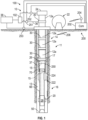
- the system 10 includes a drill string 11 and a bottomhole assembly (BHA) 20 suspended from a rig floor 13.
- the drill string 11 may be made up of a section of rigid tubulars 14 (e.g., jointed tubular).
- the drill string 11 may be made up of a rigid tubular section 14 and a non-rigid tubular section 16 (e.g., coiled tubing).
- the term rigid and non-rigid are used in the relative sense to indicate that the sections 14 and 16 exhibit different responses to an applied loading.
- a non-rigid tubular may be a continuous tubular that may be coiled and uncoiled from a reel or drum 22 (i.e., 'coilable') whereas a rigid tubular section may include segmented joints that may be organized in pipe stands 12a and may be manipulated by a top drive 24.
- the system 10 may also include rotary power devices 26, 28 (e.g., mud motors, electric motors, turbines for rotating one or more portions of the drill string 11, etc.).
- Rotary power for the drill bit 50 may be generated by a rotary power device 26 such as a motor at a connection between the rigid section 14 and the non-rigid section 16, a near bit motor 28, and / or the surface top drive 24.
- the system 10 includes a continuous circulation system 100 (CCS 100) that maintains continuous drill mud circulation in the drill string 11 as jointed connections are made up or broken in or between the rigid or non-rigid tubular section 14 or 16.
- CCS 100 continuous circulation system 100
- a pipe stand 12a or a non-rigid tubular section 16 must be physically coupled or decoupled from the drill string 11. This physical decoupling ordinarily requires prevention of fluid circulation in the drill string 11 because the drilling fluid would spill through the physical gap separating the pipe stand 12a or the non-rigid tubular 16 and the remainder of the drill string 11.
- the CCS 100 allows maintaining fluid circulation while a pipe stand 12a or a non-rigid tubular section 16 is physically decoupled from the remainder of the drill string 11.
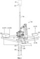
- the CCS 100 includes a flow diverter control device 32, an arm 34, a fluid line 36, and a manifold 102.
- the CCS 100 uses the manifold 102 to selectively direct drilling fluid to either the top drive 24 or the flow diverters 30 that interconnect the non-rigid tubular sections 16 or the pipe stands 12a of the rigid tubular section 14 of the remainder of the drill string 11.
- two flow paths are selected for conveying fluid into the drill string 11.
- the manifold 102 directs drilling fluid into the top drive 24.
- drilling is stopped and the arm 34 moves the flow diverter control device 32 into engagement with a flow diverter 30 on top of the drill string 11.
- Valves are activated internal to the flow diverter 30 that block axial flow from top drive 24 and allow radial flow from and to the flow diverter control device 32.
- the manifold 102 switches drilling fluid flow from the top drive 24 to the fluid line 36, which flows drilling fluid from the source 38 to the flow diverter control device 32.
- the flow diverter control device 32 supplies the flow diverter 30 with pressurized fluid.
- the top drive 24 ( FIG. 1 ) is now isolated from the drill string 11 and can be disconnected from the rigid section 14.
- drilling fluid is continuously supplied to the wellbore 13 even when the drill string 11 is not connected to the top drive 24. That is, the physical decoupling and resulting gap between the top drive 24 and the drill string 11 does not prevent drilling fluid from continuing to flow in the drill string 11.
- a new pipe stand 12a or other equipment may be added to the drill string 11
- the top drive 24 may be reconnected to the drill string 11
- the flow diverter control device may be disconnected from the flow diverter 30 after valves are adjusted to re-establish the fluid flow from the top drive 24 to the BHA 20 to allow drilling down another pipe stand 12a.
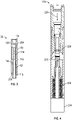
- the flow diverter 30 includes an upper end 110 and a lower end 112.
- the flow diverter 30 is fitted with flow control devices that allow fluid communication to the lower end 112 via either the upper end 110 or a radial / lateral opening.
- the flow diverter 30 includes an upper circulation valve 114, a lower circulation valve 116, and an inlet 118.
- the upper circulation valve 114 selectively blocks flow along a bore 120 connecting the upper and lower ends 110, 112.
- the lower circulation valve 116 selectively blocks flow between the bore 120 and the inlet 118.
- the flow diverter control device 32 FIG.
- the CCS 100 has two separate fluid paths that can independently circulate drilling fluid into the drill string 11 ( FIG. 1 ).
- the first fluid path is formed when the upper circulation valve 114 is open and the lower circulation valve 116 is closed.
- drilling fluid flows along the bore 120 from the upper end 110 to the lower end 112.
- the second fluid path is formed when the upper circulation valve 114 is closed and the lower circulation valve 116 is open.
- the drilling fluid flows along from the line 36 ( FIG. 2 ), across the inlet 118, into the bore 120, and down to the lower end 112.
- the flow diverter 30 is also configured to convey signals along the wellbore 13 ( FIG. 1 ).
- the signals may be conveyed in either the uphole or downhole direction.
- the signals may be encoded with information from sensor downhole or on surface such as for monitoring downhole pressure conditions or inctructions for activating, deactivating, or controlling wellbore equipment such as equipment used to manage one or more pressure parameters.
- the flow diverter 30 may include a short-hop telemetry module (not shown) that includes a signal relay device 60 energized by a power source 62.
- the signal relay device 60 may be embedded in the flow diverter 30 or fixed to the flow diverter 30 in any other suitable manner.
- the signal relay device 60 includes a suitable transceiver for receiving and transmitting data signals.
- the signal relay device 60 can include an antenna arrangement through which electromagnetic signals are sent and received through a short hop communication link.
- One non-limiting embodiment may include radio frequency (RF) signals.
- the signal relay device 60 may be a component of a one-way or a two-way telemetry system that can transmit signals (data and/or control) to the surface and/or downhole.
- signals data and/or control
- data is transmitted from one relay point to an immediately adjacent relay point, or a relay point some distance away.
- other waves may be used to transmit signals, e . g ., acoustical waves, pressure pulses, etc.
- Transmission of pressure waves as arrays enables communication with all signal relay devices 30 and BHA modules along the entire drill-string at different points of time. Generation, repeating or magnification of the pulse pressure waves can be performed with positive or negative fluid displacement values.
- Some embodiments use battery or energy harvesting systems to drive pressure wave generating modules like piezo actuated pistons or membranes, or mud sirens, which are embedded in or connected to flow diverters 30 that include signal relay devices 60.
- U.S. Pat. No. 7,230,880 shows an independent working power and communication module that may be used as an interfering device and link between the pressure wave generator on surface 262 and other modules of the BHA.
- Time synchronization of modules may be achieved by the atomic clock utilization. Generation or disturbance of interference may be used to transmit information. Some embodiments use switching between signal downlink and signal uplink transmission frequency at interference points to simplify the system. Another arrangement involves working with interfering pressure wave pairs (or triples, or more) traveling along the drill string, repeating signal to transmit at different point of times (repeating signal at least ones while traveling DH or UpHole). Built-in pressure sensors receiving signal close by interfering pair and generating an interfering pair with the next reachable signal relay device unit (s) after a "hand shake.”
- a communication system 200 uses the signal relay devices 60 ( FIG. 3 ) as part of a communication link with downhole equipment positioned along the drill string 11 ( FIG. 1 ).
- the signal relay devices may be included in wellbore equipment, such as a casing 17 ( FIG. 1 ).
- Illustrative wellbore equipment include, but are not limited to, casings, liners, casing collars, casing shoes, devices embedded in the formation, conduits (e.g., hydraulic tubing, electrical cables, pipes, etc.).
- the downhole communication link may also include a signal carrier 66 disposed along the non-rigid carrier 16 or the rigid tubulars 14 commonly referred to as wired pipe in the drill string 11.
- the signal carrier 66 may be metal wire, optical fibers, customized cement or any other suitable carrier for conveying information-containing signals.
- the signal carrier 66 may be embedded in the wall of the non-rigid section 16, the rigid tubulars 14, or the casing 17, or disposed in any wellbore equipment at the surface or downhole.
- the signal carrier 66 may also be fixed inside or outside of the non-rigid section 16, the rigid tubulars 14, or the casing 17.
- the signals may be transmitted between the signal carrier 66 and the signal relay devices 60 using a suitably configured connector 70.
- Another connector 70 that may also house electronics, communication modules and processing equipment to exchange signals between the carrier 66 and the signal relay devices 60 may form a physical connection between the rigid section 14 and the non-rigid section 16.
- signal exchange speed and bandwidth can be enhanced by continuous system analysis and consequent shift to the best fit configuration channel selection by the system (pre-programmed and autonomous) and the use of Ultimate Radio System Extension Lines (URSEL).
- URSEL Ultimate Radio System Extension Lines
- An illustrative URSEL system may be already installed at the rig site and/or installed into the wellbore.
- a signal carrier such as a fiber optic wire may be embedded in the cement used to set casing 17.
- the wellbore construction equipped with signal exchange equipment/modules as mentioned may use the embedded signal carrier to transmit and receive information-bearing signals.
- radio over fiber (RoF) technology may be used to transmit information. RoF technology modulates light by radio signal and transmits the modulated light over an optical fiber.
- RF signals may be converted to light signals that are conveyed over fiber optic wires for a distance and then converted back to RF signals.
- the communication system 200 includes a controller 202 in signal communication with the signal relay devices 60.
- the controller 202 may include suitable equipment such as a transceiver 204 to wirelessly communicate with the signal relay devices 60 using EM or RF waves 206.
- This system 200 allows continuous communication while drilling and making and breaking jointed connections.
- the same RF transmitter or transceiver might be used for rig site and down hole transmission of the signals to reduce the complexity of the used equipment. Signal shape and strength might be adjusted depending on operational environment only.
- the communication system 200 may be used to exchange information with the sensors and devices at the BHA 20 or positioned elsewhere on the string 11.
- Illustrative sensors include, but are not limited to, sensors for estimating: annulus pressure, drill string bore pressure, flow rate, near-bit direction (e . g ., BHA azimuth and inclination, BHA coordinates, etc.), temperature, vibration/dynamics, RPM, weight on bit, whirl, radial displacement, stick-slip, torque, shock, strain, stress, bending moment, bit bounce, axial thrust, friction and radial thrust as well as formation evaluation sensors such as gamma radiation sensors, acoustic sensors, resistivity or permittivity sensors, NMR sensors, pressure testing tools and sampling or coring tools.
- Illustrative devices include, but are not limited to, the following: one or memory modules and a battery pack module to store and provide back-up electric power, an information processing device that processes the data collected by the sensors, and a bidirectional data communication and power module (“BCPM") that transmits control signals between the BHA 20 and the surface as well as supplies electrical power to the BHA 20.
- the BHA 20 may also include processors programmed with instructions that can generate command signals to operate other downhole wellbore equipment. The commands may be generated using the measurements from downhole sensors such as pressure sensors.
- the system 10 may be used to control out-of-norm wellbore conditions using well control equipment positioned in the wellbore 13.
- the well control equipment may include an annulus flow restriction device 222 that hydraulically isolates one or more sections of a wellbore by selectively blocking fluid flow in the annulus 37, a bore flow restriction device 224 that selectively blocks fluid flow along a bore 15 of the drill string 11, and a bypass valve 250.
- the annulus flow restriction device 222 may be positioned along an uphole section of a non-rigid section 16 or anywhere else along the drill string 11. In one embodiment, the annulus flow restriction device 222 may form a continuous circumferential seal against a wellbore wall that controls flow in the well annulus 37.
- seals, packers and valves are used herein interchangeably to refer to flow control devices that can selectively control flow across a fluid path by increasing or decreasing a cross-sectional flow area.
- the control can include providing substantially unrestricted flow, substantially blocked flow, and providing an intermediate flow regime.
- the intermediate flow regimes are often referred to as "choking" or "throttling,” which can vary pressure in the annulus downhole of the annulus flow restriction device 222.
- the fluid barrier provided by these devices can be "zero leakage" or allow some controlled fluid leakage.
- the seals and valves may include suitable electronics in order to be responsive to control signals.
- Suitable flow control devices include packer-type devices, expandable seals, solenoid operated valves, hydraulically actuated devices, and electrically activated devices.
- the bore flow restriction device 224 may be at the uphole end of a non-rigid section 16. Alternatively or additionally, the bore flow restriction device 224 may be positioned in the rigid section 14 of the drill string 11.
- the bore flow restriction device 224 may include a flow path 226, a sealing member 228, a closure member 230, a biasing member 232, and a signal responsive actuator 234.
- the sealing member 228 and the closure member 230 may be complementary in shape such that engagement forms a fluid-tight seal along the flow path 226.
- the biasing member 232 is configured to bias the closure member 230 toward and against the sealing member 230.
- the biasing member 232 may include spring members ( e .
- the spring force of the biasing member 232 may be selected such that a preset value or range of flow rates or pressure will overcome the spring force and keep the closure member 230 in the open, unsealed position. A drop in flow rate or pressure below the range allows the biasing member 232 to urge the closure member 230 into sealing engagement with the sealing member 228 (the closed position).
- the bore flow restriction device 224 may be configured to close in response to an interruption in fluid flow and / or a backflow condition. A backflow condition may arise with the bore pressure downhole of the bore flow restriction device 224 is greater than the uphole bore pressure.
- the signal responsive actuator 234 allows the bore flow restriction device 224 to be remotely actuated with a control signal.
- the signal may be transmitted from the surface and / or from a device located in the wellbore 13 ( e . g ., the BHA 20).
- the controller 202 FIG. 1
- the signal response actuator 234 may be a hydraulic, electric, or mechanical device that can shift the closure member 230 into engagement with the sealing member 228 in response to a control signal.
- the actuator 234 may include suitable electronics to process the control signals and initiate the desired actions.
- the bore flow restriction device 224 may either completely seal the bore or partially block fluid flow in the bore.
- the closure member 230 may be a bypass valve that is configured to direct flow between the annulus 37 and the bore 15 of the drill string 11.
- the closure member 230 may include a signal response actuator 234 that can shift the closure member 230 between an open position, a closed position, and / or an intermediate position.
- the signal response actuator 234 may include suitable electronics to receive and process the control signals and to initiate the desired actions.
- communication using mud pulses may be enabled by distributing pressure sensors at selected surface locations within the continuous circulation system 100 and / or downhole locations; e.g., at the signal relay device 60 or in the bottomhole assembly 20.
- the communication may be in one direction or bidirectional.
- Such a system allows continuous communication while drilling and making and breaking jointed connections. Non-limiting embodiments having such functionality are described below.
- one or more pressure transducers may be hydraulically connected to the flow lines of the continuous circulation system 100.
- a first pressure transducer 251 may be in pressure communication with the line 36 supplying drilling fluid to the flow diverter 30 and a second pressure transducer 252 may be positioned along a flow line 36 (not shown) supplying drilling fluid to the top drive 24.
- the first and second pressure transducer 251, 252 may detect pressure signals conveyed along the fluid column inside the drill string 11.
- a third pressure transducer 253 may be positioned to be in fluid communication with the drilling fluid in the fluid annulus 37 surrounding the drill string 11.
- the third pressure transducer 253 may server as a reference pressure or may detect pressure signals conveyed along the fluid column in the annulus 37.
- the hydraulic connection or pressure communication should be sufficient to allow the transfer of pressure pulses or waves.
- the signal relay device 60 may include a fourth pressure transducer 254 in pressure communication with the bore 120 and a fifth pressure transducer 256 in pressure communication with the exterior of the signal relay device 60.
- the fourth pressure transducer 254 may detect pressure signals conveyed along the fluid column inside the drill string 11
- the fifth pressure transducer 256 may detect pressure signals conveyed along the fluid column in the annulus 37 surrounding the drill string 11.
- pressure transducers may be included elsewhere in the drill string 11 (e.g. in the BHA 20) or in other downhole or surface equipment.
- the pressure signals or pulses detected by the transducers 251-254, 256 may be generated by a signal generator located at one or more surface and / or downhole locations.
- a signal generator is any device that can produce one or more discernible pressure waves having a defined characteristic such as a shape, frequency, and / or magnitude.
- Signal generators may use vibrating elements or change a flow parameter ( e.g ., flow rate).
- Illustrative non-limiting signal generators include bypass valves, mud pulsers, sirens, vibrators, etc.
- the pressure pulses created by the signal generator can be considered encoded signals because the signals are transmitted in a manner that conveys information between two locations. This information may be data such as sensor readings, command signals, alarms, etc.
- a pulse wave generator 260 may be used to impart pressure pulses 262 into the drilling fluid flowing in the annulus 37.
- the signal generator may be a valve (not shown) at the manifold 102 that imparts pressure pulses into the fluid flowing through the bore of the drill string 11.
- a signal generator could also be positioned at the top drive 24, the pump (not shown) flowing fluid from the mud source 38, or any location along the mud flow path.
- pressure pulses may be generated by the upper or lower circulation valves 114, 116 of one or more signal relay devices 60, the annulus flow restriction device 222, and / or the bore flow restriction devices 224. Downhole pressure pulses may also be generated using signal generators (not shown) such as bypass valves, mud pulser, or sirens in the BHA 20.
- the pressure transducers 251, 252, 253 may be connected in parallel to the controller 202 of the communication system 200. Additionally, the controller 202 may be in signal communication (not shown) with pressure transducers 254, 256 embedded in the signal relay devices 60 or may be included elsewhere in the downhole equipment. As discussed previously, the controller 202 may include suitable equipment such as electrical or fiber optic wires, or the transceiver 204 to wirelessly communicate with the signal relay devices 60 using the EM or RF waves 206. The same RF transmitter or transceiver may be used for rig site and downhole transmission of the signals to reduce the complexity of the equipment. Signal shape and strength might be adjusted depending on operational environment.
- the non-rigid section 16 may be used to convey the BHA 20 into the wellbore 13. It should be noted that the drill string 11 does not require the non-rigid section 16. However, use of the non-rigid section 16 may reduce the number of pipe stands 12a and flow diverters 30 required to reach a desired target depth.
- the rigid section 14 may be connected to the non-rigid section 16 with the connector 70. Thereafter, the flow diverters 30 may be used to interconnect the sections of pipe 12a used to form the rigid section 14. As successive pipe joints 12a are added to the rigid section 14, the CCS 100 maintains a continuous flow of drilling fluid along the drill string 11.
- the pressure applied to the formation remains relatively constant or can be managed within a desired range.
- the drill bit 50 may be rotated by one or more of the downhole motor 28, the rotary power device 26 positioned at the connector 70, and the top drive 24.
- the signal generator(s) and pressure transducer(s) cooperate to form communication links that operate even when the drill string 11 is broken; i.e., a pipe stand 12 is physically separated from the drill string 11.
- the signal generators downhole and / or at the surface may transmit pressure pulses that flow along the fluid column inside the drill string 11 and / or in the annulus 37.
- Communication uplinks i.e., transmitting information to the surface, may be accomplished by using the pressure transducers 251, 252, 253 to detect pressure pulses generated by downhole signal generators.
- Communication downlinks i.e., transmitting information to a downhole location, may be accomplished by using the pressure transducers 254, 256 to detect pressure pulses generated by surface signal generators.
- Communication between two downhole locations may be accomplished by using the pressure transducers 254, 256 of one signal relay device 60 and a signal generator of another signal relay device or a signal generator or pressure transducer located elsewhere along the drill string 11 (e.g., a mud pulser, a bypass valve, a siren, or a pressure transducer at the BHA 20).
- a signal generator of another signal relay device or a signal generator or pressure transducer located elsewhere along the drill string 11 e.g., a mud pulser, a bypass valve, a siren, or a pressure transducer at the BHA 20.
- the mud pulse signal communication is not interrupted when pipe 12a is added to or removed from the drill string 11.
- drilling mud is still circulating even though a pipe stand is physically decoupled from the drill string 11, which enables mud pulse signals to be conveyed between the surface and downhole. Therefore, the pressure transducers 251-254, 256, which are in communication with the circulating mud, can detect pressure signals imparted to the flowing fluid. As a result, communication uplinks and downlinks are maintained throughout the disconnections.
- the communication links convey information between at least two locations along a flow path of the circulating drilling fluid irrespective whether the CCS 100 selects a first fluid path through the top drive the drill string or a second fluid path through the flow diverter to convey the fluid into the drill string.
- the system 10 may utilize reverse circulation.
- reverse circulation the drilling mud is pumped into the annulus 37.
- the drilling mud and entrained cuttings return via a bore of the drill string 11.
- the instrumentation described above enables uninterrupted unidirectional or bi-direction communication via mud pulses.
- reverse circulation itself may have variants.
- crossover subs may divert annulus flow into the drill string bore 15 while diverting drill string flow into the annulus.
- flow may be "reverse" in some sections of the well but “conventional” in other parts of the well.
- pressure information may be continuously transmitted by the communication system 200 or the mud pulse telemetry. Therefore, pressure adjustments may be done in real time or near-real time.
- deep drilling situations that have tight pressure windows and formations with changing formation pressure may be managed more efficiently because wellbore pressure management devices can be rapidly and accurately adjusted.
- this enhanced control may enable drilling to be performed while the well is in an underbalanced pressure condition. In many instances, drilling in an underbalanced condition yields enhanced rates of penetration.
- the pressure information may indicate that corrective action may be needed to contain an undesirable condition.
- the pressure information received may indicate that an enhanced risk for a potential "kick," or pressure spike exists.
- One exemplary response may include the controller 202 transmitting a control signal using the communication system 200 to the annular flow restriction device 222.
- the annular flow restriction device 222 may radially expand and seal against the adjacent wellbore wall.
- the fluid annulus 37 of the wellbore 13 downhole of the flow restriction device 222 may hydraulically isolated from the remainder of the wellbore 13.
- the controller 202 may send a control signal to the bore flow restriction device 224.
- the bore flow restriction device 224 may seal the bore of the drill string 11.
- the bore of the drill string 11 downhole of the flow restriction device 224 may hydraulically isolated.
- the actuation of either or both of the flow restriction devices 222, 224 in this manner may isolate the downhole section of the wellbore 13 and thereby reduce the risk of the pressure kick.
- remedial action may be taken such as bleeding off the pressure kick, increasing mud weight, etc.
- it may be desired to isolate the wellbore either temporarily or permanently. Isolating the wellbore may be done by leaving the entire drill string 11 in the wellbore 13.
- the rigid section 14 may be disconnected from the non-rigid section 16 and pulled out the wellbore 13.
- the wellbore 13 is isolated by the non-rigid section 16 and the flow restriction devices 222, 224.
- the BHA 20 may use one or more downhole controllers that are programmed to also monitor pressure conditions, determine whether an undesirable condition exists, and transmit the necessary control signals to the flow restriction devices 222, 224, bypass valve 250, and / or other equipment. These actions may be taken autonomously or semi-autonomously.
- the BHA 20 may include devices that enhance drilling efficiency or allow for directional drilling.
- the BHA 20 may include a thruster that applies a thrust to urge the drill bit 50 against a wellbore bottom.
- the thrust functions as the weight-on-bit (WOB) that would often be created by the weight of the drill string.
- WOB weight-on-bit
- One or more stabilizers that may be selectively clamped to the wall may be configured to have thrust-bearing capabilities to take up the reaction forces caused by the thruster.
- the thruster allows for drilling in non-vertical wellbore trajectories where there may be insufficient WOB to keep the drill bit 50 pressed against the wellbore bottom.
- Some embodiments of the BHA 20 may also include a steering device. Suitable steering arrangements may include, but are not limited to, bent subs, drilling motors with bent housings, selectively eccentric inflatable stabilizers, a pad-type steering devices that apply force to a wellbore wall, "point the bit" steering systems, etc. As discussed previously, stabilizers may be used to stabilize and strengthen the sections 14, 16.
- the drill string 11 may be used for non-drilling activities such as casing installation, liner installation, casing / liner expansion, well perforation, fracturing, gravel packing, acid washing, tool installation or removal, etc. In such configurations, the drill bit 50 may not be present.
- aspects of the present disclosure provide a system for deep drilling (e.g ., tight pressure windows) and drilling into formations with changing formation pressure (e.g ., depleted zones).
- Systems according to the present disclosure provide ECD control (equivalent circulating density control) for such situations. These systems may allow the exploration and production of deep high enthalpy geothermal energy due to the ability to manage tight pressure windows in deep crystalline rock.
Landscapes
- Engineering & Computer Science (AREA)
- Geology (AREA)
- Life Sciences & Earth Sciences (AREA)
- Mining & Mineral Resources (AREA)
- Physics & Mathematics (AREA)
- Environmental & Geological Engineering (AREA)
- Fluid Mechanics (AREA)
- General Life Sciences & Earth Sciences (AREA)
- Geochemistry & Mineralogy (AREA)
- Mechanical Engineering (AREA)
- Acoustics & Sound (AREA)
- Remote Sensing (AREA)
- Geophysics (AREA)
- Earth Drilling (AREA)
Claims (9)
- Système destiné à effectuer une opération de puits de forage tandis qu'un fluide circule dans un puits de forage, comprenant :- un train de forage (11) comprenant au moins une première section tubulaire (14, 12a) et une seconde section tubulaire (16, 12a), chaque section tubulaire étant conçue pour être reliée à et pour être détachée du train de forage (11) ;- un déflecteur d'écoulement (30) conçu pour interrelier l'une parmi la première section tubulaire (14, 12a) et la seconde section tubulaire (16, 12a) avec un reste du train de forage (11), ledit déflecteur d'écoulement (30) étant relié au sommet du reste du train de forage ;- un système de circulation de fluide faisant circuler le fluide de forage à travers au moins une partie du train de forage (11), le système de circulation de fluide comprenant un dispositif de circulation continue (100) comprenant un dispositif de commande du déflecteur d'écoulement (32), un bras (34) conçu, lorsque l'une des première ou seconde sections tubulaires doit être ajoutée au reste du train de forage, pour déplacer le dispositif de commande du déflecteur d'écoulement (32) en prise avec le déflecteur d'écoulement (30), le dispositif de circulation continue (100) comprenant en outre un collecteur (102) qui dirige sélectivement le fluide de forage vers soit un entraînement supérieur (24) soit le dispositif de commande du déflecteur d'écoulement (32) pour former au moins un premier trajet de fluide et un second trajet de fluide, un seul du premier trajet de fluide et du second trajet de fluide faisant circuler le fluide de forage dans le train de forage (11) à un moment spécifié ;le déflecteur d'écoulement (30) comprenant une extrémité supérieure (110), une extrémité inférieure (112), un alésage (120) reliant l'extrémité supérieure (110) et l'extrémité inférieure (112), une vanne de circulation supérieure (114), une vanne de circulation inférieure (116) et une ouverture latérale (118), la vanne de circulation supérieure (114) étant agencée pour bloquer sélectivement l'écoulement de fluide le long de l'alésage (120) et de l'extrémité inférieure (112), la vanne de circulation inférieure (116) étant agencée pour bloquer sélectivement l'écoulement de fluide entre l'ouverture latérale (118) et l'alésage (120) ;et le dispositif de commande du déflecteur d'écoulement (32) comprenant un actionneur de vanne supérieur pour décaler la vanne de circulation supérieure (114) entre une position ouverte et une position fermée et un actionneur de vanne inférieur pour décaler la vanne de circulation inférieure (116) entre une position ouverte et une position fermée, lorsque l'une parmi la première section tubulaire (14, 12a) ou la seconde section tubulaire (16, 12a) doit être ajoutée au reste du train de forage et lorsque le dispositif de commande du déflecteur d'écoulement (32) est mis en prise avec le déflecteur d'écoulement (30), le second trajet de fluide étant formé en décalant la vanne de circulation supérieure (114) dans la position fermée et la vanne de circulation inférieure (116) dans la position ouverte de sorte que le fluide de forage dirigé vers le dispositif de commande du déflecteur d'écoulement (32) peut s'écouler depuis l'ouverture latérale (118) vers l'extrémité inférieure (112) du déflecteur d'écoulement (30) ;après que la première section tubulaire (14, 12a) ou la seconde section tubulaire (16, 12a) a été ajoutée au reste du train de forage et avant que le dispositif de commande du déflecteur d'écoulement (32) ne soit désolidarisé du déflecteur d'écoulement (30), le premier trajet de fluide étant formé en décalant la vanne de circulation supérieure (114) dans la position ouverte et la vanne de circulation inférieure (116) dans la position fermée de sorte que, pendant le forage, après que le dispositif de commande du déflecteur d'écoulement (32) est désolidarisé du déflecteur d'écoulement (30), le fluide de forage dirigé vers l'entraînement supérieur (24) pouvant s'écouler le long de l'alésage (120) depuis l'extrémité supérieure (110) vers l'extrémité inférieure (112) du déflecteur d'écoulement (30),- au moins un générateur de signal (260) en communication hydraulique avec le fluide de forage en circulation, l'au moins un générateur de signal (260) étant configuré pour communiquer au moins un signal de pression dans le fluide de forage en circulation ; et- au moins un transducteur de pression (254, 256) positionné dans le déflecteur d'écoulement (30) et en communication de pression avec le fluide de forage en circulation et configuré pour détecter l'au moins un signal de pression transmis,
l'au moins un générateur de signal (260) et l'au moins un transducteur de pression (254, 256) formant une liaison de communication, la liaison de communication étant configurée pour transporter des informations entre au moins deux emplacements le long d'un trajet d'écoulement du fluide de forage en circulation, indépendamment du fait que le premier trajet de fluide ou le second trajet de fluide est sélectionné par le dispositif de circulation continue (100) pour transporter le fluide de forage dans le train de forage (11). - Système selon la revendication 1, dans lequel l'au moins un générateur de signal (260) est positionné à un emplacement de surface.
- Système selon la revendication 1, dans lequel la liaison de communication est bidirectionnelle.
- Système selon la revendication 1, dans lequel l'au moins un générateur de signal (260) est positionné le long du train de forage (11).
- Système selon la revendication 4, dans lequel au moins un transducteur de pression est en communication hydraulique avec un espace annulaire entourant le train de forage (11).
- Système selon la revendication 1, dans lequel l'au moins un générateur de signal (260) comporte au moins un premier générateur de signal (260) positionné près de la surface et un second générateur de signal (260) positionné sur le train de forage (11).
- Procédé pour effectuer une opération de puits de forage tandis qu'un fluide circule dans un puits de forage, le procédé comprenant :- la fourniture d'un système pour effectuer une opération de puits de forage selon la revendication 1 ;- le transport du reste du train de forage (11) dans le puits de forage ;- la circulation du fluide de forage à travers au moins une partie du train de forage (11) à l'aide du système de circulation de fluide ;- la sélection de l'un des premier et second trajets de fluide à travers lequel le fluide de forage est transporté dans le train de forage (11);- la fourniture d'au moins un signal de pression dans le fluide de forage en circulation à l'aide de l'au moins un générateur de signal (260) en communication hydraulique avec le fluide de forage en circulation ; et- la détection de l'au moins un signal de pression transmis à l'aide de l'au moins un transducteur de pression (254, 256).
- Procédé selon la revendication 7, dans lequel l'au moins un générateur de signal (260) est positionné à un emplacement de surface.
- Procédé selon la revendication 7, dans lequel au moins un transducteur de pression (254, 256) est en communication hydraulique avec un espace annulaire entourant le train de forage (11).
Applications Claiming Priority (2)
| Application Number | Priority Date | Filing Date | Title |
|---|---|---|---|
| US14/961,364 US10494885B2 (en) | 2013-02-06 | 2015-12-07 | Mud pulse telemetry with continuous circulation drilling |
| PCT/US2016/065146 WO2017100189A1 (fr) | 2015-12-07 | 2016-12-06 | Télémétrie par impulsions dans la boue de forage à forage avec circulation continue |
Publications (3)
| Publication Number | Publication Date |
|---|---|
| EP3387221A1 EP3387221A1 (fr) | 2018-10-17 |
| EP3387221A4 EP3387221A4 (fr) | 2019-08-07 |
| EP3387221B1 true EP3387221B1 (fr) | 2023-02-22 |
Family
ID=59014158
Family Applications (1)
| Application Number | Title | Priority Date | Filing Date |
|---|---|---|---|
| EP16873674.2A Active EP3387221B1 (fr) | 2015-12-07 | 2016-12-06 | Télémétrie par impulsions dans la boue de forage à forage avec circulation continue |
Country Status (3)
| Country | Link |
|---|---|
| EP (1) | EP3387221B1 (fr) |
| AU (1) | AU2016367135A1 (fr) |
| WO (1) | WO2017100189A1 (fr) |
Family Cites Families (6)
| Publication number | Priority date | Publication date | Assignee | Title |
|---|---|---|---|---|
| US6920085B2 (en) * | 2001-02-14 | 2005-07-19 | Halliburton Energy Services, Inc. | Downlink telemetry system |
| US7320370B2 (en) * | 2003-09-17 | 2008-01-22 | Schlumberger Technology Corporation | Automatic downlink system |
| CA2894621C (fr) * | 2012-12-17 | 2019-04-30 | Evolution Engineering Inc. | Appareil de telemetrie d'impulsion de boue ayant un capteur de pression et procede de fonctionnement de celui-la |
| US9784096B2 (en) * | 2012-12-28 | 2017-10-10 | Halliburton Energy Services, Inc. | Expanded mud pulse telemetry |
| US9249648B2 (en) * | 2013-02-06 | 2016-02-02 | Baker Hughes Incorporated | Continuous circulation and communication drilling system |
| BR112016006040A2 (pt) * | 2013-10-31 | 2017-08-01 | Halliburton Energy Services Inc | sistema de telemetria de pulso para a comunicação de dados digitais, e, métodos de transmissão de dados desenvolvidos em um furo de poço para uma unidade de superfície e de fabricação de uma unidade de telemetria de pulso de fundo de poço |
-
2016
- 2016-12-06 WO PCT/US2016/065146 patent/WO2017100189A1/fr not_active Ceased
- 2016-12-06 EP EP16873674.2A patent/EP3387221B1/fr active Active
- 2016-12-06 AU AU2016367135A patent/AU2016367135A1/en not_active Abandoned
Also Published As
| Publication number | Publication date |
|---|---|
| EP3387221A1 (fr) | 2018-10-17 |
| AU2016367135A1 (en) | 2018-07-12 |
| WO2017100189A1 (fr) | 2017-06-15 |
| EP3387221A4 (fr) | 2019-08-07 |
Similar Documents
| Publication | Publication Date | Title |
|---|---|---|
| US10494885B2 (en) | Mud pulse telemetry with continuous circulation drilling | |
| CA2600843C (fr) | Systemes et methodes de regulation pour la gestion en temps reel de la pression a fond de forage (controle de la densite equivalente du fluide de forage) | |
| EP2665894B1 (fr) | Raccord double femelle de circulation à télémesure | |
| EP2917462B1 (fr) | Isolation de puits | |
| US11105179B2 (en) | Tester valve below a production packer | |
| US20150267500A1 (en) | Sealing apparatus and method | |
| US20040124994A1 (en) | High data rate borehole telemetry system | |
| WO2007103245A2 (fr) | Procédés et dispositif de forage d'agrandissement de trou orientable et automatique | |
| NO342370B1 (no) | System for kommunikasjon med flere kommunikasjonsveier langs en borestreng | |
| WO2010088339A2 (fr) | Dispositif de forage d'agrandissement de trou et ses procédés d'utilisation | |
| US9404358B2 (en) | Wiper plug for determining the orientation of a casing string in a wellbore | |
| US10329861B2 (en) | Liner running tool and anchor systems and methods | |
| AU2012370307B2 (en) | Piston tractor system for use in subterranean wells | |
| WO2014042629A1 (fr) | Appareil et procédé de transmission d'informations par fluide de forage | |
| US8839883B2 (en) | Piston tractor system for use in subterranean wells | |
| WO2015047262A1 (fr) | Bouchon de cimentation permettant de déterminer l'orientation d'une colonne de tubage dans un puits de forage | |
| US11513247B2 (en) | Data acquisition systems | |
| CA2879085C (fr) | Systeme de poussee a piston de tube dans tube | |
| EP3387221A1 (fr) | Télémétrie par impulsions dans la boue de forage à forage avec circulation continue | |
| US10151161B2 (en) | Well telemetry with autonomous robotic diver | |
| US20210172305A1 (en) | Real-time system for hydraulic fracturing | |
| WO2025088194A1 (fr) | Appareil de fond de trou destiné à être utilisé avec une colonne de travail continue |
Legal Events
| Date | Code | Title | Description |
|---|---|---|---|
| STAA | Information on the status of an ep patent application or granted ep patent |
Free format text: STATUS: THE INTERNATIONAL PUBLICATION HAS BEEN MADE |
|
| PUAI | Public reference made under article 153(3) epc to a published international application that has entered the european phase |
Free format text: ORIGINAL CODE: 0009012 |
|
| STAA | Information on the status of an ep patent application or granted ep patent |
Free format text: STATUS: REQUEST FOR EXAMINATION WAS MADE |
|
| 17P | Request for examination filed |
Effective date: 20180703 |
|
| AK | Designated contracting states |
Kind code of ref document: A1 Designated state(s): AL AT BE BG CH CY CZ DE DK EE ES FI FR GB GR HR HU IE IS IT LI LT LU LV MC MK MT NL NO PL PT RO RS SE SI SK SM TR |
|
| AX | Request for extension of the european patent |
Extension state: BA ME |
|
| DAV | Request for validation of the european patent (deleted) | ||
| DAX | Request for extension of the european patent (deleted) | ||
| A4 | Supplementary search report drawn up and despatched |
Effective date: 20190704 |
|
| RIC1 | Information provided on ipc code assigned before grant |
Ipc: E21B 21/01 20060101ALI20190628BHEP Ipc: E21B 21/10 20060101ALI20190628BHEP Ipc: E21B 47/18 20120101AFI20190628BHEP |
|
| STAA | Information on the status of an ep patent application or granted ep patent |
Free format text: STATUS: EXAMINATION IS IN PROGRESS |
|
| 17Q | First examination report despatched |
Effective date: 20200422 |
|
| GRAP | Despatch of communication of intention to grant a patent |
Free format text: ORIGINAL CODE: EPIDOSNIGR1 |
|
| STAA | Information on the status of an ep patent application or granted ep patent |
Free format text: STATUS: GRANT OF PATENT IS INTENDED |
|
| INTG | Intention to grant announced |
Effective date: 20221130 |
|
| GRAS | Grant fee paid |
Free format text: ORIGINAL CODE: EPIDOSNIGR3 |
|
| GRAA | (expected) grant |
Free format text: ORIGINAL CODE: 0009210 |
|
| STAA | Information on the status of an ep patent application or granted ep patent |
Free format text: STATUS: THE PATENT HAS BEEN GRANTED |
|
| RAP3 | Party data changed (applicant data changed or rights of an application transferred) |
Owner name: BAKER HUGHES HOLDINGS LLC |
|
| AK | Designated contracting states |
Kind code of ref document: B1 Designated state(s): AL AT BE BG CH CY CZ DE DK EE ES FI FR GB GR HR HU IE IS IT LI LT LU LV MC MK MT NL NO PL PT RO RS SE SI SK SM TR |
|
| REG | Reference to a national code |
Ref country code: GB Ref legal event code: FG4D |
|
| REG | Reference to a national code |
Ref country code: CH Ref legal event code: EP |
|
| REG | Reference to a national code |
Ref country code: DE Ref legal event code: R096 Ref document number: 602016077994 Country of ref document: DE |
|
| REG | Reference to a national code |
Ref country code: AT Ref legal event code: REF Ref document number: 1549640 Country of ref document: AT Kind code of ref document: T Effective date: 20230315 Ref country code: IE Ref legal event code: FG4D |
|
| REG | Reference to a national code |
Ref country code: NO Ref legal event code: T2 Effective date: 20230222 |
|
| REG | Reference to a national code |
Ref country code: LT Ref legal event code: MG9D |
|
| REG | Reference to a national code |
Ref country code: NL Ref legal event code: MP Effective date: 20230222 |
|
| P01 | Opt-out of the competence of the unified patent court (upc) registered |
Effective date: 20230526 |
|
| REG | Reference to a national code |
Ref country code: AT Ref legal event code: MK05 Ref document number: 1549640 Country of ref document: AT Kind code of ref document: T Effective date: 20230222 |
|
| PG25 | Lapsed in a contracting state [announced via postgrant information from national office to epo] |
Ref country code: RS Free format text: LAPSE BECAUSE OF FAILURE TO SUBMIT A TRANSLATION OF THE DESCRIPTION OR TO PAY THE FEE WITHIN THE PRESCRIBED TIME-LIMIT Effective date: 20230222 Ref country code: PT Free format text: LAPSE BECAUSE OF FAILURE TO SUBMIT A TRANSLATION OF THE DESCRIPTION OR TO PAY THE FEE WITHIN THE PRESCRIBED TIME-LIMIT Effective date: 20230622 Ref country code: NL Free format text: LAPSE BECAUSE OF FAILURE TO SUBMIT A TRANSLATION OF THE DESCRIPTION OR TO PAY THE FEE WITHIN THE PRESCRIBED TIME-LIMIT Effective date: 20230222 Ref country code: LV Free format text: LAPSE BECAUSE OF FAILURE TO SUBMIT A TRANSLATION OF THE DESCRIPTION OR TO PAY THE FEE WITHIN THE PRESCRIBED TIME-LIMIT Effective date: 20230222 Ref country code: LT Free format text: LAPSE BECAUSE OF FAILURE TO SUBMIT A TRANSLATION OF THE DESCRIPTION OR TO PAY THE FEE WITHIN THE PRESCRIBED TIME-LIMIT Effective date: 20230222 Ref country code: HR Free format text: LAPSE BECAUSE OF FAILURE TO SUBMIT A TRANSLATION OF THE DESCRIPTION OR TO PAY THE FEE WITHIN THE PRESCRIBED TIME-LIMIT Effective date: 20230222 Ref country code: ES Free format text: LAPSE BECAUSE OF FAILURE TO SUBMIT A TRANSLATION OF THE DESCRIPTION OR TO PAY THE FEE WITHIN THE PRESCRIBED TIME-LIMIT Effective date: 20230222 Ref country code: AT Free format text: LAPSE BECAUSE OF FAILURE TO SUBMIT A TRANSLATION OF THE DESCRIPTION OR TO PAY THE FEE WITHIN THE PRESCRIBED TIME-LIMIT Effective date: 20230222 |
|
| PG25 | Lapsed in a contracting state [announced via postgrant information from national office to epo] |
Ref country code: SE Free format text: LAPSE BECAUSE OF FAILURE TO SUBMIT A TRANSLATION OF THE DESCRIPTION OR TO PAY THE FEE WITHIN THE PRESCRIBED TIME-LIMIT Effective date: 20230222 Ref country code: PL Free format text: LAPSE BECAUSE OF FAILURE TO SUBMIT A TRANSLATION OF THE DESCRIPTION OR TO PAY THE FEE WITHIN THE PRESCRIBED TIME-LIMIT Effective date: 20230222 Ref country code: IS Free format text: LAPSE BECAUSE OF FAILURE TO SUBMIT A TRANSLATION OF THE DESCRIPTION OR TO PAY THE FEE WITHIN THE PRESCRIBED TIME-LIMIT Effective date: 20230622 Ref country code: GR Free format text: LAPSE BECAUSE OF FAILURE TO SUBMIT A TRANSLATION OF THE DESCRIPTION OR TO PAY THE FEE WITHIN THE PRESCRIBED TIME-LIMIT Effective date: 20230523 Ref country code: FI Free format text: LAPSE BECAUSE OF FAILURE TO SUBMIT A TRANSLATION OF THE DESCRIPTION OR TO PAY THE FEE WITHIN THE PRESCRIBED TIME-LIMIT Effective date: 20230222 |
|
| PG25 | Lapsed in a contracting state [announced via postgrant information from national office to epo] |
Ref country code: SM Free format text: LAPSE BECAUSE OF FAILURE TO SUBMIT A TRANSLATION OF THE DESCRIPTION OR TO PAY THE FEE WITHIN THE PRESCRIBED TIME-LIMIT Effective date: 20230222 Ref country code: RO Free format text: LAPSE BECAUSE OF FAILURE TO SUBMIT A TRANSLATION OF THE DESCRIPTION OR TO PAY THE FEE WITHIN THE PRESCRIBED TIME-LIMIT Effective date: 20230222 Ref country code: EE Free format text: LAPSE BECAUSE OF FAILURE TO SUBMIT A TRANSLATION OF THE DESCRIPTION OR TO PAY THE FEE WITHIN THE PRESCRIBED TIME-LIMIT Effective date: 20230222 Ref country code: DK Free format text: LAPSE BECAUSE OF FAILURE TO SUBMIT A TRANSLATION OF THE DESCRIPTION OR TO PAY THE FEE WITHIN THE PRESCRIBED TIME-LIMIT Effective date: 20230222 Ref country code: CZ Free format text: LAPSE BECAUSE OF FAILURE TO SUBMIT A TRANSLATION OF THE DESCRIPTION OR TO PAY THE FEE WITHIN THE PRESCRIBED TIME-LIMIT Effective date: 20230222 |
|
| REG | Reference to a national code |
Ref country code: DE Ref legal event code: R097 Ref document number: 602016077994 Country of ref document: DE |
|
| PG25 | Lapsed in a contracting state [announced via postgrant information from national office to epo] |
Ref country code: SK Free format text: LAPSE BECAUSE OF FAILURE TO SUBMIT A TRANSLATION OF THE DESCRIPTION OR TO PAY THE FEE WITHIN THE PRESCRIBED TIME-LIMIT Effective date: 20230222 |
|
| PLBE | No opposition filed within time limit |
Free format text: ORIGINAL CODE: 0009261 |
|
| STAA | Information on the status of an ep patent application or granted ep patent |
Free format text: STATUS: NO OPPOSITION FILED WITHIN TIME LIMIT |
|
| 26N | No opposition filed |
Effective date: 20231123 |
|
| PG25 | Lapsed in a contracting state [announced via postgrant information from national office to epo] |
Ref country code: SI Free format text: LAPSE BECAUSE OF FAILURE TO SUBMIT A TRANSLATION OF THE DESCRIPTION OR TO PAY THE FEE WITHIN THE PRESCRIBED TIME-LIMIT Effective date: 20230222 |
|
| PG25 | Lapsed in a contracting state [announced via postgrant information from national office to epo] |
Ref country code: IT Free format text: LAPSE BECAUSE OF FAILURE TO SUBMIT A TRANSLATION OF THE DESCRIPTION OR TO PAY THE FEE WITHIN THE PRESCRIBED TIME-LIMIT Effective date: 20230222 |
|
| REG | Reference to a national code |
Ref country code: DE Ref legal event code: R119 Ref document number: 602016077994 Country of ref document: DE |
|
| REG | Reference to a national code |
Ref country code: CH Ref legal event code: PL |
|
| PG25 | Lapsed in a contracting state [announced via postgrant information from national office to epo] |
Ref country code: LU Free format text: LAPSE BECAUSE OF NON-PAYMENT OF DUE FEES Effective date: 20231206 |
|
| PG25 | Lapsed in a contracting state [announced via postgrant information from national office to epo] |
Ref country code: MC Free format text: LAPSE BECAUSE OF FAILURE TO SUBMIT A TRANSLATION OF THE DESCRIPTION OR TO PAY THE FEE WITHIN THE PRESCRIBED TIME-LIMIT Effective date: 20230222 |
|
| REG | Reference to a national code |
Ref country code: BE Ref legal event code: MM Effective date: 20231231 |
|
| PG25 | Lapsed in a contracting state [announced via postgrant information from national office to epo] |
Ref country code: MC Free format text: LAPSE BECAUSE OF FAILURE TO SUBMIT A TRANSLATION OF THE DESCRIPTION OR TO PAY THE FEE WITHIN THE PRESCRIBED TIME-LIMIT Effective date: 20230222 Ref country code: LU Free format text: LAPSE BECAUSE OF NON-PAYMENT OF DUE FEES Effective date: 20231206 |
|
| REG | Reference to a national code |
Ref country code: IE Ref legal event code: MM4A |
|
| PG25 | Lapsed in a contracting state [announced via postgrant information from national office to epo] |
Ref country code: DE Free format text: LAPSE BECAUSE OF NON-PAYMENT OF DUE FEES Effective date: 20240702 Ref country code: IE Free format text: LAPSE BECAUSE OF NON-PAYMENT OF DUE FEES Effective date: 20231206 |
|
| PG25 | Lapsed in a contracting state [announced via postgrant information from national office to epo] |
Ref country code: BE Free format text: LAPSE BECAUSE OF NON-PAYMENT OF DUE FEES Effective date: 20231231 |
|
| PG25 | Lapsed in a contracting state [announced via postgrant information from national office to epo] |
Ref country code: FR Free format text: LAPSE BECAUSE OF NON-PAYMENT OF DUE FEES Effective date: 20231231 |
|
| PG25 | Lapsed in a contracting state [announced via postgrant information from national office to epo] |
Ref country code: CH Free format text: LAPSE BECAUSE OF NON-PAYMENT OF DUE FEES Effective date: 20231231 |
|
| PG25 | Lapsed in a contracting state [announced via postgrant information from national office to epo] |
Ref country code: IE Free format text: LAPSE BECAUSE OF NON-PAYMENT OF DUE FEES Effective date: 20231206 Ref country code: FR Free format text: LAPSE BECAUSE OF NON-PAYMENT OF DUE FEES Effective date: 20231231 Ref country code: DE Free format text: LAPSE BECAUSE OF NON-PAYMENT OF DUE FEES Effective date: 20240702 Ref country code: CH Free format text: LAPSE BECAUSE OF NON-PAYMENT OF DUE FEES Effective date: 20231231 Ref country code: BE Free format text: LAPSE BECAUSE OF NON-PAYMENT OF DUE FEES Effective date: 20231231 |
|
| PG25 | Lapsed in a contracting state [announced via postgrant information from national office to epo] |
Ref country code: BG Free format text: LAPSE BECAUSE OF FAILURE TO SUBMIT A TRANSLATION OF THE DESCRIPTION OR TO PAY THE FEE WITHIN THE PRESCRIBED TIME-LIMIT Effective date: 20230222 |
|
| PG25 | Lapsed in a contracting state [announced via postgrant information from national office to epo] |
Ref country code: BG Free format text: LAPSE BECAUSE OF FAILURE TO SUBMIT A TRANSLATION OF THE DESCRIPTION OR TO PAY THE FEE WITHIN THE PRESCRIBED TIME-LIMIT Effective date: 20230222 |
|
| PG25 | Lapsed in a contracting state [announced via postgrant information from national office to epo] |
Ref country code: CY Free format text: LAPSE BECAUSE OF FAILURE TO SUBMIT A TRANSLATION OF THE DESCRIPTION OR TO PAY THE FEE WITHIN THE PRESCRIBED TIME-LIMIT; INVALID AB INITIO Effective date: 20161206 |
|
| PG25 | Lapsed in a contracting state [announced via postgrant information from national office to epo] |
Ref country code: HU Free format text: LAPSE BECAUSE OF FAILURE TO SUBMIT A TRANSLATION OF THE DESCRIPTION OR TO PAY THE FEE WITHIN THE PRESCRIBED TIME-LIMIT; INVALID AB INITIO Effective date: 20161206 |
|
| PG25 | Lapsed in a contracting state [announced via postgrant information from national office to epo] |
Ref country code: TR Free format text: LAPSE BECAUSE OF FAILURE TO SUBMIT A TRANSLATION OF THE DESCRIPTION OR TO PAY THE FEE WITHIN THE PRESCRIBED TIME-LIMIT Effective date: 20230222 |
|
| PGFP | Annual fee paid to national office [announced via postgrant information from national office to epo] |
Ref country code: GB Payment date: 20251120 Year of fee payment: 10 |
|
| PGFP | Annual fee paid to national office [announced via postgrant information from national office to epo] |
Ref country code: NO Payment date: 20251121 Year of fee payment: 10 |