EP3387241B1 - Capot de moteur hybride en plastique composite et son procédé de fabrication - Google Patents
Capot de moteur hybride en plastique composite et son procédé de fabrication Download PDFInfo
- Publication number
- EP3387241B1 EP3387241B1 EP16822524.1A EP16822524A EP3387241B1 EP 3387241 B1 EP3387241 B1 EP 3387241B1 EP 16822524 A EP16822524 A EP 16822524A EP 3387241 B1 EP3387241 B1 EP 3387241B1
- Authority
- EP
- European Patent Office
- Prior art keywords
- polymer material
- reinforced polymer
- fiber
- thermoplastic resin
- engine cover
- Prior art date
- Legal status (The legal status is an assumption and is not a legal conclusion. Google has not performed a legal analysis and makes no representation as to the accuracy of the status listed.)
- Not-in-force
Links
Images



Classifications
-
- F—MECHANICAL ENGINEERING; LIGHTING; HEATING; WEAPONS; BLASTING
- F02—COMBUSTION ENGINES; HOT-GAS OR COMBUSTION-PRODUCT ENGINE PLANTS
- F02F—CYLINDERS, PISTONS OR CASINGS, FOR COMBUSTION ENGINES; ARRANGEMENTS OF SEALINGS IN COMBUSTION ENGINES
- F02F7/00—Casings, e.g. crankcases
- F02F7/0065—Shape of casings for other machine parts and purposes, e.g. utilisation purposes, safety
- F02F7/0073—Adaptations for fitting the engine, e.g. front-plates or bell-housings
-
- F—MECHANICAL ENGINEERING; LIGHTING; HEATING; WEAPONS; BLASTING
- F02—COMBUSTION ENGINES; HOT-GAS OR COMBUSTION-PRODUCT ENGINE PLANTS
- F02F—CYLINDERS, PISTONS OR CASINGS, FOR COMBUSTION ENGINES; ARRANGEMENTS OF SEALINGS IN COMBUSTION ENGINES
- F02F7/00—Casings, e.g. crankcases
- F02F7/0065—Shape of casings for other machine parts and purposes, e.g. utilisation purposes, safety
- F02F7/0073—Adaptations for fitting the engine, e.g. front-plates or bell-housings
- F02F2007/0075—Front covers
Definitions
- This disclosure pertains generally, but not by way of limitation, to a nonmetallic engine cover, and more particularly, to a composite-plastic hybrid front engine accessory drive cover.
- a combustion engine is typically coupled to several engine drive accessories, such as an alternator, a power steering pump, an air conditioning compressor, an engine water pump, tensioner pulley, etc. It has been common practice in the automotive industry to mount these various engine drive accessories to a front of the combustion engine on a front engine accessory drive cover.
- the front engine accessory drive cover is typically configured to allow the engine drive accessories to connect with corresponding components.
- a first embodiment relates to an engine cover according to claim 1.
- a second embodiment relates to a method of manufacturing an engine cover according to claim 12.
- FIGS. 1 and 2 illustrate an exterior and interior perspective view, respectively, of a front engine accessory drive cover 100 according to an aspect of the present disclosure.
- the front engine accessory drive cover 100 includes a housing 102 having an exterior side 104 and an interior side 106.
- the housing 102 may be mounted to a vehicle engine (not shown).
- the front engine accessory drive cover 100 may be utilized with any engine, such as an internal combustion engine, a hybrid engine, and the like.
- the front engine accessory drive cover 100 may also be utilized with an electric vehicle having an electric motor.
- the description will reference an engine in a non-limiting manner.
- the shape and configuration of the housing 102 depends upon the engine to which the housing 102 is to be mounted and the various accessories and components required by the vehicle in general. Accordingly, if the front engine accessory drive cover 100 were to be utilized with a V6 engine, it may be designed and configured differently than if the front engine accessory drive cover 100 were to be mounted to a different engine configuration, such as an inline-triple (13) engine. For example, a front engine accessory drive cover 100 coupled to the engine via a hanging-type mount may require additional structural support compared to other designs. Furthermore, an inline-triple engine is typically subject to higher vibrational frequencies during operation, which may require differences in structural configuration and material composition to meet performance requirements.
- front engine accessory drive cover 100 design of the front engine accessory drive cover 100 and the locations of the various accessories may vary and still achieve the desired aspects of the present disclosure. It therefore should be understood that the front engine accessory drive cover 100 shown in the drawings is merely illustrative, and additional geometric modifications are contemplated in accordance with the present disclosure.
- the housing 102 is configured such that the engine drive accessories or components may be attached to the exterior side 104.
- a predetermined number of accessories may be mounted to and/or enclosed by the housing 102. It should be understood that the location and number of engine drive accessories may be varied.
- the engine drive accessories may include one or more of a generator, an alternator, a water pump, a power steering pump, an air conditioning compressor, a crankshaft damper, a belt tensioner, an idler, and the like.
- Other components that may be mounted to the housing 102 include a vacuum pump, a fuel injection pump, an oil pump, a cam drive, and the like. These components can be incorporated with the front engine accessory drive cover 100 to form a front engine drive system.
- the drive accessories are mounted to the housing 102 by bolts or other mechanical fasteners known in the art at locations along the exterior side 104 and/or interior side 106 of the front engine accessory drive cover 100.
- the engine accessories may be press fit onto the front engine accessory drive cover 100.
- the housing 102 defines a plurality of mount holes for the engine drive accessories described above.
- the housing 102 defines a first drive accessory mount hole 110 and a second drive accessory mount hole 112.
- the housing 102 also defines an engine mount cavity 114 configured to facilitate mounting of the front engine accessory drive cover 100 onto the engine (not shown).
- additional mount holes and cavities may be included on the housing 102 to mount numerous other drive accessories mentioned above, depending on the drive accessories needed for the corresponding engine.
- the features of the front engine accessory drive cover 100 shown in FIGS. 1 and 2 are provided for exemplary purposes only and are not meant to be limiting.
- the front engine accessory drive cover 100 may be mounted onto the engine (not shown) via the attachment holes 108.
- a plurality of bolts or other mechanical fasteners known in the art may be placed through the attachment holes 108 in order to secure the front engine accessory drive cover 100 to the engine (not shown).
- a plurality of compression limiters 124 may be arranged in the attachment holes 108.
- the compression limiters 124 may be configured as metal inserts to provide bolt clearance so that the compression limiters 124 withstand a compressive force induced during an assembly of the mating mechanical fastener or bolt in order to secure the front engine accessory drive cover 100 in a more robust manner. If utilized, nuts or other types of mechanical fasteners may be molded into the reinforcing structure 122 as well.
- the housing 102 also may have a corrugated sections 116 formed onto or in the interior side 106.
- the corrugated sections 116 may increase strength of the housing 102 in this particular region of the front engine accessory drive cover 100.
- the corrugated sections 116 may help minimize an overall noise level transmitted via acoustics or structure to a passenger compartment of the vehicle and otherwise assist in reducing noise-vibration-harshness characteristics of the front engine accessory drive system.
- the corrugated sections 116 are formed within the engine mount cavity 114.
- the housing 102 may include ribs formed onto or into other surfaces of the housing 102 that may need additional structural support, including on the exterior side 104 and/or interior side 106.
- the ribs 126 may be arranged around the second drive accessory mount hole 112. The ribs 126 may increase strength of the housing 102 in this particular region of the front engine accessory drive cover 100.
- a strengthening portion 128 may be configured as a cylindrical portion that encompasses the second drive accessory mount hole 112. The strengthening portion 128 may increase strength of the housing 102 in this particular region of the front engine accessory drive cover 100.
- a strengthening portion 130 may be arranged around the first drive accessory mount hole 110.
- the strengthening portion 130 may increase strength of the housing 102 in this particular region of the front engine accessory drive cover 100.
- the front engine accessory drive cover 100 may also include at least one edge groove 132 to provide additional support when the front engine accessory drive cover 100 is mounted to an engine (not shown) along a contact surface 134.
- the edge groove 132 may increase strength of the housing 102 in this particular region of the front engine accessory drive cover 100.
- the edge groove 132 may be formed on one or more edges of the housing 102.
- the front engine accessory drive cover 100 may include cross ribs 136 that span across a width, a height, and/or other direction along the housing 102.
- the cross ribs 136 may increase strength of the housing 102 in this particular region of the front engine accessory drive cover 100.
- the design and configuration of the housing 102 provides stiffness and locates resonant frequencies of the assembled system in the least objectionable places. These features can be accomplished through system design rather than individual component design.
- the front engine accessory drive cover 100 includes a contoured laminate 120 and a reinforcing structure 122.
- the contoured laminate 120 may have a contoured geometry configured for use as a housing cover.
- the contoured laminate may be curved or contoured along the width and/or length and may have various cross-sections suitable for use as a housing cover.
- the contoured laminate 120 has a generally U-shaped cross-section.
- the material composition of the contoured laminate 120 and reinforcing structure 122 will be described in further detail with reference to FIGS. 3A and 3B .
- the contoured laminate 120 and reinforcing structure 122 together form the housing 102 of the front engine accessory drive cover 100.
- the reinforcing structure 122 may be overlaid on the contoured laminate 120 with at least one smooth transitioning angle between the contoured laminate 120 and the reinforcing structure 122. As illustrated in FIGS. 1 and 2 , some regions of the housing 102 may be composed by an overlap between the contoured laminate 120 and the reinforcing structure 122 while other regions may be composed of only the contoured laminate 120 or the reinforcing structure 122.
- FIG. 3A illustrates the contoured laminate 120 for use in the front engine accessory drive cover 100.
- the first fiber-reinforced polymer material includes a first thermoplastic resin.
- the contoured laminate 120 may be made from a first fiber-reinforced polymer material.
- the first fiber-reinforced polymer material may include a laminate made from at least one of a uni-directional tape, a woven fabric, and a non-woven fabric.
- the laminate may be made through a melt process, from a chemical solution, from a powder, or by film impregnation.
- the woven and non-woven fabric materials may be made from the first thermoplastic resin.
- thermoplastic resins include polyacetal, polyacrylic, styrene acrylonitrile, acrylonitrile-butadiene-styrene (ABS), polycarbonate, polystyrene, polyethylene, polyphenylene ether, polypropylene, polyethylene terephthalate, polybutylene terephthalate, Nylons (Nylon-6, Nylon-6/6, Nylon-6/10, Nylon-6/12, Nylon-11 or Nylon-12, for example), polyamideimide, polyarylate, polyurethane, ethylene propylene diene rubber (EPR), ethylene propylene diene monomer (EPDM), polyarylsulfone, polyethersulfone, polyphenylene sulfide, polyvinyl chloride, polysulfone, polyetherimide, polytetrafluoroethylene, fluorinated ethylene propylene, perfluoroalkoxyethylene, polychlorotrifluoroethylene, polyvinylid
- the thermoplastic resin may also be propriety resin materials, such as Noryl GTX TM , which is a blend of polyamide and modified polyphenylene ether, or Thermocomp RC008 TM , which is a Nylon 66 resin. It is anticipated that any thermoplastic resin may be used in the present disclosure that is capable of being sufficiently softened by heat to permit fusing and/or molding without being chemically or thermally decomposed.
- the first thermoplastic resin is a blend of polyamide and modified polyphenylene ether polymer.
- the first fiber-reinforced polymer material of the contoured laminate 120 may also include at least one type of continuous fiber material designed to help provide strength to the contoured laminate 120.
- Fibers suitable for use in the disclosure include glass fibers, carbon fibers, graphite fibers, synthetic organic fibers, particularly high modulus organic fibers such as para- and meta-aramid fibers, nylon fibers, polyester fibers, or any of the thermoplastic resins mentioned above that are suitable for use as fibers, natural fibers such as hemp, sisal, jute, flax, coir, kenaf and cellulosic fibers, mineral fibers such as basalt, mineral wool (e.g., rock or slag wool), Wollastonite, alumina silica, and the like, or mixtures thereof, metal fibers, metalized natural and/or synthetic fibers, ceramic fibers, or mixtures thereof.
- the fibers selected for the first fiber-reinforced polymer material of the contoured laminate 120 are continuous carbon-fibers.
- the fibers selected for the first laminate-composite material may be continuous filaments embedded in the thermoplastic resin. During manufacturing, the fibers are typically formed into sheets and impregnated with the thermoplastic resin to form the composite-laminate material.
- the fiber content in the contoured laminate 120 may be between 10% to 50%, for example. The fiber content may be within the range of 10% to 20%, 20% to 30%, 30% to 40%, or 40% to 50% by weight, based upon the total weight of the contoured laminate.
- the first fiber-reinforced polymer material is a continuous carbon-fiber impregnated with a blend of polyamide and modified polyphenylene ether polymer.
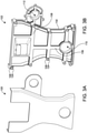
- FIG. 3B illustrates the reinforcing structure 122 for use in the front engine accessory drive cover 100.
- the reinforcing structure 122 may be made from a second reinforced polymer material.
- the second reinforced polymer material may be the same as the first fiber-reinforced polymer materials.
- the second reinforced polymer material may be different from the first fiber-reinforced polymer material.
- the second reinforced polymer material may be a chopped-fiber reinforced polymer while the first fiber-reinforced polymer material is a continuous-fiber reinforced polymer. Because the chopped fibers may have random orientations compared to continuous fibers, the finished composite-laminate material may have improved in-plane stiffness, bending stiffness, strength, and other structural properties.
- the second reinforced polymer material may be selected for portions of the front engine accessory drive cover 100 that may need additional support, such as the strengthening portion 128, the strengthening portion 130, the edge groove 132, the contact surface 134, the cross ribs 136, and the like.
- the second reinforced polymer material for the reinforcing structure 122 also may include a second thermoplastic resin.
- the second thermoplastic resin may be selected from the non-exhaustive list of first thermoplastic resins described above with respect to the contoured laminate 120.
- the second thermoplastic resin of the reinforcing structure 122 may be different than the first thermoplastic resin selected for the contoured laminate 120, it may be desirable that the first thermoplastic resin and the second thermoplastic resin share a common polymeric material.
- the first thermoplastic resin is a blend of polyamide and modified polyphenylene ether polymer while the second thermoplastic resin is polyamide.
- the first thermoplastic resin and the second thermoplastic resin may have the polymer polyamide in common.
- the shared polymer allows for improved chemical bonding between the contoured laminate 120 and the reinforcing structure 122 during the manufacturing process of the front engine accessory drive cover 100.
- the specific materials mentioned above are merely described for exemplary purposes. Additional combinations of thermoplastic resins may be selected for the contoured laminate 120 and/or the reinforcing structure 122 to meet desired material properties for the specific geometry of the front engine accessory drive cover 100.
- the second reinforced polymer material for the reinforcing structure 122 may include chopped polymeric fibers, fillers or flakes.
- the chopped polymeric fibers may be short-chopped fibers or long-chopped fibers.
- short-chopped fibers may have an average length of 2 millimeter (mm) or less, such as 1 mm.
- long-chopped fibers may have an average length of 2 mm or more.
- the long-chopped fibers may have an average length of 5 mm or greater, or 10 mm or greater.
- Suitable materials for the chopped-fiber may be selected from the non-exhaustive list of fiber materials described above with respect to the contoured laminate 120.
- the fibers for the reinforcing structure 122 are short-chopped carbon fibers.
- compositions of the second reinforced polymer material for the contoured laminate 120 and/or reinforcing structure 122 may include additional fillers.
- additional fillers Non-limiting examples of other fillers which may be included are glass fibers, mica, talc, clay, silica and Wollastonite. Minor amounts of other materials may also be included to modify specific properties of the composition.
- PTFE polytetrafluoroethylene
- brominated flame retardant polymers e.g., brominated PC
- phosphorus-containing organic flame retardants such as resorcinol diphosphate, bisphenol A diphosphate or tetraxylyl piperazine diphosphamide
- PTFE may also be included in larger amounts, up to about 25%, to improve wear resistance
- polyethylene may be included in amounts up to about 2% to improve mold release characteristics.
- Impact modifiers such as styrene-butadiene-styrene (SBS) may be included in amounts up to about 10% to improve impact strength.
- Flow promoters such as hydrogenated polyterpene may also be included in amounts up to about 15%.
- the second reinforced polymer material for the contoured laminate 120 and/or reinforcing structure 122 may also include a conductive filler.
- Suitable conductive fillers include solid conductive metallic fillers or inorganic fillers coated with a solid metallic filler. These solid conductive metal fillers may be an electrically conductive metal or alloy that does not melt under conditions used when incorporating them into the polymeric resin, and fabricating finished articles therefrom. Metals such as aluminum, copper, magnesium, chromium, tin, nickel, silver, iron, titanium, and mixtures including any one of the foregoing metals may be incorporated into the thermoplastic resin as solid metal particles.
- Table 1 below shows a comparison between performances of the front engine accessory drive cover 100 constructed consistent with the disclosure and a conventional front engine accessory drive cover.
- the conventional front engine accessory drive cover was made from aluminum and the front engine accessory drive cover 100 was made from a composite-plastic material. The natural frequencies of different modes were tested for both designs at an operating temperature of 100 °C.
- the front engine accessory drive cover 100 had less mass compared to the aluminum front engine accessory drive cover. In one aspect, the front engine accessory drive cover 100 had a reduction of 15% mass compared to the aluminum front engine accessory drive cover. Similar mass reduction may be expected for other geometries.
- the composite-plastic design showed comparable frequency values.
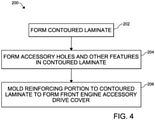
- FIG. 4 illustrates a process 200 for manufacturing a front engine accessory drive cover 100 according to an aspect of the present disclosure.
- the contoured laminate 120 of the front engine accessory drive cover 100 may be formed.
- the contoured laminate 120 may be cut prior to molding to form the desired shape including the first drive accessory mount hole 110, the second drive accessory mount hole 112, the engine mount cavity 114, and the like.
- the laminate may be further formed as a single component through a molding process.
- the molding process may be used to form the desired shape and other features of the contoured laminate 120 of the front engine accessory drive cover 100, such as first drive accessory mount hole 110, the second drive accessory mount hole 112, the engine mount cavity 114, and the like, as well as the contours, corrugations, and overall shape of the contoured laminate 120.
- one or more of the mount holes and other features may be formed after the molding process.
- the second reinforced polymer material for the reinforcing structure 122 may be injected onto the contoured laminate 120 and overmolded or through-molded to form the front engine accessory drive cover 100.
- FIG. 5 illustrates an example of through-molding at a cross-section of the front engine accessory drive cover 100 at a button location 138 shown in FIGS. 1 and 2 .
- the reinforcing structure 122 may flow through an injection hole 140 formed into the contoured laminate 120.
- the through-molding of the reinforcing structure 122 may provide improved bonding of the reinforcing structure 122 onto the contoured laminate 120 compared to overmolding.
- the front engine accessory drive cover 100 may have a plurality of button locations 138 where the reinforcing structure 122 is through-molded on the contoured laminate 120.
- the reinforcing structure 122 may be formed such that the reinforcing structure is overlaid on the contoured laminate 120 with at least one smooth transitioning angle between the reinforcing structure 122 and the contoured laminate 120.
- Step 206 may further include forming the strengthening portion 128, the strengthening portion 130, the edge groove 132, the contact surface 134, the cross ribs 136, and the like.
- step 206 may further include arranging the plurality of compression limiters 124 at desired locations for the attachment holes 108. If utilized, nuts or other types of mechanical fasteners may be molded into the reinforcing structure 122 as well.
- a front engine accessory drive cover 100 constructed consistent with the present disclosure may reduce weight by around 15% compared to a metal design. Further, a front engine accessory drive cover 100 may have the following properties (1) high stiffness, (2) high temperature performance, (3) chemical resistance, (4) improved fatigue properties, and (5) improved creep properties.
- High stiffness of the front engine accessory drive cover 100 is achieved through a combination of material and geometry as described above.
- Thermoplastic materials described in the present disclosure may have a high Young's Modulus, which may be almost 40 to 50% of that of aluminum. Additional stiffness may be achieved through strategic placing of the corrugated sections 116, the ribs 126, the strengthening portion 128, the strengthening portion 130, the edge groove 132, and the cross ribs 136.
- High temperature performance of the front engine accessory drive cover 100 may be achieved through placing of continuous carbon laminates at strategic locations such as overhanging portions and the main body of the housing 102. This may include unattached areas around magnet covers, accessory pulleys, and other drive accessories. In some aspects, this may not include areas which have higher depth such as the engine mount. The areas with higher depth may be stiffened instead with an optimized rib structure since the depth gives package space to place rib structures, such as the ribs 126.
- Chemical resistance may be achieved through the selection of materials as described above. This may include materials such as NORYL TM GTX and RC008, which have excellent chemical resistance compared to other materials known in the art.
- composite-laminate materials may have better fatigue properties than metal since they have inherent voids which do not allow cracks to propagate.
- creep at load bearing attachment areas may be prevented through metal nuts or compression limiters 124, which may be insert molded into, placed through, or otherwise attached to the front engine accessory drive cover 100.
- a front engine accessory drive cover 100 constructed consistent with the present disclosure exhibits frequencies in the same range as incumbent metal designs.
- a front engine accessory drive cover 100 may be within ⁇ 10% of the performance of metal designs at high temperatures, such as 100 °C.
- the first type may be a hard mount where all translational and rotational motion is constrained.
- the first type may be used to mount the front engine accessory drive cover 100 to the engine block.
- the second type may be a soft mount used at the locations where the front engine accessory drive cover 100 is joined to other major engine structures, such as an oil pan, a cylinder head, or the like.
- the third type may be a hanging accessory mount.
- the third type may be used for attachment of various drive accessories, such as the water pump, to the front engine accessory drive cover 100. There may be little or no stiffness contribution and some lumped mass contribution from the drive accessories to the mount.
- the fourth type may be a pure sealing attachment.
- the fourth type may be used for attachment of the front engine accessory drive cover 100 to minor non-structural parts, such as regulatory magnet covers.
Landscapes
- Engineering & Computer Science (AREA)
- Chemical & Material Sciences (AREA)
- Combustion & Propulsion (AREA)
- Mechanical Engineering (AREA)
- General Engineering & Computer Science (AREA)
- Cylinder Crankcases Of Internal Combustion Engines (AREA)
Claims (15)
- Capot moteur (100) comprenant :un stratifié profilé (120) définissant une pluralité de trous d'accessoire configurée pour recevoir une pluralité d'accessoires, dans lequel le stratifié profilé a une section transversale généralement en forme de U ;une structure de renfort ondulée (122) superposée sur le stratifié profilé et se raccordant au stratifié profilé avec au moins un angle de transition régulière entre le stratifié profilé et la structure de renfort ondulée, la structure de renfort ondulée définissant une pluralité de trous d'attache (108) ; dans lequel le stratifié profilé et la structure de renfort forment ensemble un boîtier (102) du capot d'entraînement d'accessoire pour moteur avant ; etune pluralité d'éléments de fixation, au moins l'un de la pluralité d'éléments de fixation étant agencé dans au moins l'un de la pluralité de trous d'attache.
- Capot moteur selon la revendication 1, dans lequel :le stratifié profilé est fabriqué à partir d'un premier matériau de polymère renforcé de fibres, etla structure de renfort ondulée est fabriquée à partir d'un deuxième matériau de polymère renforcé différent du premier matériau de polymère renforcé de fibres, la structure de renfort ondulée étant surmoulée ou formée par moulage traversant sur une première portion du stratifié profilé.
- Capot moteur selon l'une quelconque des revendications 1 à 2, dans lequel le deuxième matériau de polymère renforcé est un polymère renforcé de fibres coupées tandis que le premier matériau de polymère renforcé de fibres est un polymère renforcé de fibres continues.
- Capot moteur selon l'une quelconque des revendications 1 à 2, dans lequel le premier matériau de polymère renforcé de fibres comprend une première résine thermoplastique et/ou le deuxième matériau de polymère renforcé comprend une deuxième résine thermoplastique qui est identique à la première résine thermoplastique ou différente de celle-ci.
- Capot moteur selon la revendication 4, dans lequel la deuxième résine thermoplastique est le polyamide.
- Capot moteur selon l'une quelconque des revendications 3 à 5, dans lequel la première résine thermoplastique comprend du polyamide et la deuxième résine thermoplastique comprend du polyamide.
- Capot moteur selon l'une quelconque des revendications 3 à 6, dans lequel la première résine thermoplastique est une combinaison de polyamide et de polymère de polyphénylène éther.
- Capot moteur selon l'une quelconque des revendications 1 à 7, dans lequel les fibres continues sont au moins les unes des suivantes : des fibres de carbone, des fibres de verre, et des fibres d'aramide.
- Capot moteur selon l'une quelconque des revendications 1 à 8, dans lequel le premier matériau de polymère renforcé de fibres comprend un stratifié fabriqué à partir d'au moins l'un des suivants : un ruban unidirectionnel, une étoffe tissée, et une étoffe non tissée.
- Capot moteur selon l'une quelconque des revendications 1 à 9, dans lequel le deuxième matériau de polymère renforcé comprend en outre au moins les uns des suivants : des charges, et des copeaux.
- Capot moteur selon l'une quelconque des revendications 1 à 10, dans lequel le premier matériau de polymère renforcé de fibres est un polyamide renforcé de fibres de carbone continues et un polymère de polyphénylène éther modifié et le deuxième matériau de polymère renforcé est un polyamide renforcé de fibres de carbone courtes coupées.
- Procédé de fabrication d'un capot moteur (100), le procédé de fabrication comprenant :la formation d'un stratifié profilé (120) fabriqué à partir d'un premier matériau de polymère renforcé de fibres, dans lequel le stratifié profilé a une section transversale généralement en forme de U ;la formation d'une pluralité de trous d'accessoire dans le stratifié profilé configurés pour recevoir une pluralité d'accessoires d'entraînement de moteur ;le surmoulage et la formation par moulage traversant d'une structure de renfort (122) fabriquée à partir d'un deuxième matériau de polymère renforcé sur au moins une portion du stratifié profilé, le deuxième matériau de polymère renforcé étant différent du premier matériau de polymère renforcé de fibres ; etla formation d'une pluralité de trous d'attache (108) dans la structure de renfort, la pluralité de trous d'attache étant configurée pour recevoir une pluralité d'éléments de fixation.
- Procédé selon la revendication 12, dans lequel le premier matériau de polymère renforcé de fibres comprend une première résine thermoplastique et le deuxième matériau de polymère renforcé comprend une deuxième résine thermoplastique différente de la première résine thermoplastique.
- Procédé selon la revendication 13, dans lequel la première résine thermoplastique comprend du polyamide et la deuxième résine thermoplastique comprend du polyamide.
- Procédé selon la revendication 14, dans lequel le premier matériau de polymère renforcé de fibres est un polyamide renforcé de fibres de carbone continues et un polymère de polyphénylène éther modifié et le deuxième matériau de polymère renforcé est un polyamide renforcé de fibres de carbone courtes coupées.
Applications Claiming Priority (2)
| Application Number | Priority Date | Filing Date | Title |
|---|---|---|---|
| IN3685DE2015 | 2015-11-11 | ||
| PCT/IB2016/056811 WO2017081655A1 (fr) | 2015-11-11 | 2016-11-11 | Capot de moteur hybride en plastique composite et son procédé de fabrication |
Publications (2)
| Publication Number | Publication Date |
|---|---|
| EP3387241A1 EP3387241A1 (fr) | 2018-10-17 |
| EP3387241B1 true EP3387241B1 (fr) | 2022-03-16 |
Family
ID=57737761
Family Applications (1)
| Application Number | Title | Priority Date | Filing Date |
|---|---|---|---|
| EP16822524.1A Not-in-force EP3387241B1 (fr) | 2015-11-11 | 2016-11-11 | Capot de moteur hybride en plastique composite et son procédé de fabrication |
Country Status (5)
| Country | Link |
|---|---|
| US (1) | US20180266358A1 (fr) |
| EP (1) | EP3387241B1 (fr) |
| CN (1) | CN108350830A (fr) |
| AU (1) | AU2016352821B2 (fr) |
| WO (1) | WO2017081655A1 (fr) |
Families Citing this family (6)
| Publication number | Priority date | Publication date | Assignee | Title |
|---|---|---|---|---|
| US20200376729A1 (en) * | 2019-05-31 | 2020-12-03 | Microsoft Technology Licensing, Llc | Techniques for overmolding thermoplastics onto a spray primed polymer substrate |
| USD950606S1 (en) * | 2019-11-19 | 2022-05-03 | Transportation Ip Holdings, Llc | Forward end housing |
| JP7480682B2 (ja) | 2020-11-17 | 2024-05-10 | トヨタ紡織株式会社 | 内燃機関のカバー |
| JP7658215B2 (ja) | 2021-08-19 | 2025-04-08 | スズキ株式会社 | 内燃機関のカバー部材の取付構造 |
| JP7487725B2 (ja) * | 2021-11-29 | 2024-05-21 | トヨタ自動車株式会社 | 車両用エンジンのシリンダブロック |
| USD1035511S1 (en) * | 2022-06-02 | 2024-07-16 | Rapidrev LLC | Vehicle engine cover |
Citations (1)
| Publication number | Priority date | Publication date | Assignee | Title |
|---|---|---|---|---|
| DE102013213773A1 (de) * | 2012-07-19 | 2014-01-23 | GM Global Technology Operations, LLC (n.d. Ges. d. Staates Delaware) | Multidirektionale asymmetrische Oberflächen für Gehäuse und Gehäuseabdeckungen sowie Brennkraftmaschinen, die diese aufweisen |
Family Cites Families (6)
| Publication number | Priority date | Publication date | Assignee | Title |
|---|---|---|---|---|
| JP2000257442A (ja) * | 1999-03-04 | 2000-09-19 | Idemitsu Petrochem Co Ltd | 自動車エンジンルーム内用軽量樹脂成形品およびその製造方法 |
| US7735908B2 (en) * | 2007-07-24 | 2010-06-15 | Gm Global Technology Operations, Inc. | Vehicle hood with sandwich inner structure |
| DE102011111744B4 (de) * | 2011-08-24 | 2013-09-05 | Daimler Ag | Steuergehäusemodul und Herstellungsverfahren |
| DE102012205078A1 (de) * | 2012-03-29 | 2013-10-02 | Zf Friedrichshafen Ag | Ölwanne |
| US20140186166A1 (en) * | 2012-12-27 | 2014-07-03 | General Electric Company | Hybrid Continuous Fiber Chopped Fiber Polymer Composite Structure |
| US10012117B2 (en) * | 2013-10-08 | 2018-07-03 | Basf Se | Structural oil pan |
-
2016
- 2016-11-11 US US15/774,700 patent/US20180266358A1/en not_active Abandoned
- 2016-11-11 EP EP16822524.1A patent/EP3387241B1/fr not_active Not-in-force
- 2016-11-11 AU AU2016352821A patent/AU2016352821B2/en not_active Expired - Fee Related
- 2016-11-11 CN CN201680064965.4A patent/CN108350830A/zh active Pending
- 2016-11-11 WO PCT/IB2016/056811 patent/WO2017081655A1/fr not_active Ceased
Patent Citations (1)
| Publication number | Priority date | Publication date | Assignee | Title |
|---|---|---|---|---|
| DE102013213773A1 (de) * | 2012-07-19 | 2014-01-23 | GM Global Technology Operations, LLC (n.d. Ges. d. Staates Delaware) | Multidirektionale asymmetrische Oberflächen für Gehäuse und Gehäuseabdeckungen sowie Brennkraftmaschinen, die diese aufweisen |
Also Published As
| Publication number | Publication date |
|---|---|
| US20180266358A1 (en) | 2018-09-20 |
| AU2016352821A1 (en) | 2018-04-19 |
| AU2016352821B2 (en) | 2019-08-08 |
| WO2017081655A1 (fr) | 2017-05-18 |
| EP3387241A1 (fr) | 2018-10-17 |
| CN108350830A (zh) | 2018-07-31 |
Similar Documents
| Publication | Publication Date | Title |
|---|---|---|
| EP3387241B1 (fr) | Capot de moteur hybride en plastique composite et son procédé de fabrication | |
| US5375569A (en) | Multi polymer structures for internal combustion engines | |
| KR101315741B1 (ko) | 치수안정성이 우수한 전기자동차용 배터리 팩 케이스 어셈블리와 그 제조 방법 | |
| CN104736362B (zh) | 车辆侧门结构及其制造方法和使用方法及具有该侧门的车辆 | |
| US20080277987A1 (en) | Composite seat back frame | |
| KR20200033776A (ko) | 전기자동차용 배터리 케이스 | |
| US20180031027A1 (en) | Crankshaft assemblies and methods of manufacturing the same | |
| CN103963588A (zh) | 由纤维增强塑料制得的用于汽车车轮悬架的横向导臂 | |
| US20120325578A1 (en) | Muffler assembly and method of making | |
| CN111452445A (zh) | 夹层结构体、使用该夹层结构体的一体化成型品及它们的制造方法 | |
| JP2004534169A (ja) | 接着剤で接合されたエンジンインテイクマニホールドアセンブリー | |
| KR20120029420A (ko) | 폴리아미드 복합 구조체 및 그 제조 방법 | |
| JP2014501322A (ja) | ノイズ減衰組成物 | |
| HK1042868A1 (zh) | 塑料和金屬的層壓組件及其製備方法 | |
| KR20060029682A (ko) | 개선된 엔진 흡기 매니폴드 조립체 | |
| US9610719B2 (en) | Fastening resin structure and method for manufacturing the same | |
| KR20160133605A (ko) | 자동차 부품용 보강재 및 이를 포함하는 자동차 부품 | |
| WO2018117182A1 (fr) | Procédé de production de marchandises usinées, et marchandises usinées | |
| US20120244301A1 (en) | Component with a hollow body that can be subjected to internal pressure | |
| JP2005239806A (ja) | 炭素繊維強化熱可塑性樹脂成形品 | |
| CN107630763B (zh) | 复合内燃发动机 | |
| US8980395B2 (en) | Composite parts joined by a flexible construct | |
| KR102347323B1 (ko) | 경량형 고강도 복합 부직포를 이용한 섬유 엔진커버 | |
| EP3303064A1 (fr) | Cloison comprenant une structure de support et un élément acoustique | |
| JP7028654B2 (ja) | プレス成形方法 |
Legal Events
| Date | Code | Title | Description |
|---|---|---|---|
| STAA | Information on the status of an ep patent application or granted ep patent |
Free format text: STATUS: UNKNOWN |
|
| STAA | Information on the status of an ep patent application or granted ep patent |
Free format text: STATUS: THE INTERNATIONAL PUBLICATION HAS BEEN MADE |
|
| PUAI | Public reference made under article 153(3) epc to a published international application that has entered the european phase |
Free format text: ORIGINAL CODE: 0009012 |
|
| STAA | Information on the status of an ep patent application or granted ep patent |
Free format text: STATUS: REQUEST FOR EXAMINATION WAS MADE |
|
| 17P | Request for examination filed |
Effective date: 20180614 |
|
| AK | Designated contracting states |
Kind code of ref document: A1 Designated state(s): AL AT BE BG CH CY CZ DE DK EE ES FI FR GB GR HR HU IE IS IT LI LT LU LV MC MK MT NL NO PL PT RO RS SE SI SK SM TR |
|
| AX | Request for extension of the european patent |
Extension state: BA ME |
|
| DAV | Request for validation of the european patent (deleted) | ||
| DAX | Request for extension of the european patent (deleted) | ||
| GRAP | Despatch of communication of intention to grant a patent |
Free format text: ORIGINAL CODE: EPIDOSNIGR1 |
|
| STAA | Information on the status of an ep patent application or granted ep patent |
Free format text: STATUS: GRANT OF PATENT IS INTENDED |
|
| INTG | Intention to grant announced |
Effective date: 20220111 |
|
| GRAS | Grant fee paid |
Free format text: ORIGINAL CODE: EPIDOSNIGR3 |
|
| GRAA | (expected) grant |
Free format text: ORIGINAL CODE: 0009210 |
|
| STAA | Information on the status of an ep patent application or granted ep patent |
Free format text: STATUS: THE PATENT HAS BEEN GRANTED |
|
| AK | Designated contracting states |
Kind code of ref document: B1 Designated state(s): AL AT BE BG CH CY CZ DE DK EE ES FI FR GB GR HR HU IE IS IT LI LT LU LV MC MK MT NL NO PL PT RO RS SE SI SK SM TR |
|
| REG | Reference to a national code |
Ref country code: GB Ref legal event code: FG4D |
|
| REG | Reference to a national code |
Ref country code: CH Ref legal event code: EP Ref country code: DE Ref legal event code: R096 Ref document number: 602016070119 Country of ref document: DE |
|
| REG | Reference to a national code |
Ref country code: IE Ref legal event code: FG4D |
|
| REG | Reference to a national code |
Ref country code: AT Ref legal event code: REF Ref document number: 1476033 Country of ref document: AT Kind code of ref document: T Effective date: 20220415 |
|
| REG | Reference to a national code |
Ref country code: LT Ref legal event code: MG9D |
|
| REG | Reference to a national code |
Ref country code: NL Ref legal event code: MP Effective date: 20220316 |
|
| PG25 | Lapsed in a contracting state [announced via postgrant information from national office to epo] |
Ref country code: SE Free format text: LAPSE BECAUSE OF FAILURE TO SUBMIT A TRANSLATION OF THE DESCRIPTION OR TO PAY THE FEE WITHIN THE PRESCRIBED TIME-LIMIT Effective date: 20220316 Ref country code: RS Free format text: LAPSE BECAUSE OF FAILURE TO SUBMIT A TRANSLATION OF THE DESCRIPTION OR TO PAY THE FEE WITHIN THE PRESCRIBED TIME-LIMIT Effective date: 20220316 Ref country code: NO Free format text: LAPSE BECAUSE OF FAILURE TO SUBMIT A TRANSLATION OF THE DESCRIPTION OR TO PAY THE FEE WITHIN THE PRESCRIBED TIME-LIMIT Effective date: 20220616 Ref country code: LT Free format text: LAPSE BECAUSE OF FAILURE TO SUBMIT A TRANSLATION OF THE DESCRIPTION OR TO PAY THE FEE WITHIN THE PRESCRIBED TIME-LIMIT Effective date: 20220316 Ref country code: HR Free format text: LAPSE BECAUSE OF FAILURE TO SUBMIT A TRANSLATION OF THE DESCRIPTION OR TO PAY THE FEE WITHIN THE PRESCRIBED TIME-LIMIT Effective date: 20220316 Ref country code: BG Free format text: LAPSE BECAUSE OF FAILURE TO SUBMIT A TRANSLATION OF THE DESCRIPTION OR TO PAY THE FEE WITHIN THE PRESCRIBED TIME-LIMIT Effective date: 20220616 |
|
| REG | Reference to a national code |
Ref country code: AT Ref legal event code: MK05 Ref document number: 1476033 Country of ref document: AT Kind code of ref document: T Effective date: 20220316 |
|
| PG25 | Lapsed in a contracting state [announced via postgrant information from national office to epo] |
Ref country code: LV Free format text: LAPSE BECAUSE OF FAILURE TO SUBMIT A TRANSLATION OF THE DESCRIPTION OR TO PAY THE FEE WITHIN THE PRESCRIBED TIME-LIMIT Effective date: 20220316 Ref country code: GR Free format text: LAPSE BECAUSE OF FAILURE TO SUBMIT A TRANSLATION OF THE DESCRIPTION OR TO PAY THE FEE WITHIN THE PRESCRIBED TIME-LIMIT Effective date: 20220617 Ref country code: FI Free format text: LAPSE BECAUSE OF FAILURE TO SUBMIT A TRANSLATION OF THE DESCRIPTION OR TO PAY THE FEE WITHIN THE PRESCRIBED TIME-LIMIT Effective date: 20220316 |
|
| PG25 | Lapsed in a contracting state [announced via postgrant information from national office to epo] |
Ref country code: NL Free format text: LAPSE BECAUSE OF FAILURE TO SUBMIT A TRANSLATION OF THE DESCRIPTION OR TO PAY THE FEE WITHIN THE PRESCRIBED TIME-LIMIT Effective date: 20220316 |
|
| PG25 | Lapsed in a contracting state [announced via postgrant information from national office to epo] |
Ref country code: SM Free format text: LAPSE BECAUSE OF FAILURE TO SUBMIT A TRANSLATION OF THE DESCRIPTION OR TO PAY THE FEE WITHIN THE PRESCRIBED TIME-LIMIT Effective date: 20220316 Ref country code: SK Free format text: LAPSE BECAUSE OF FAILURE TO SUBMIT A TRANSLATION OF THE DESCRIPTION OR TO PAY THE FEE WITHIN THE PRESCRIBED TIME-LIMIT Effective date: 20220316 Ref country code: RO Free format text: LAPSE BECAUSE OF FAILURE TO SUBMIT A TRANSLATION OF THE DESCRIPTION OR TO PAY THE FEE WITHIN THE PRESCRIBED TIME-LIMIT Effective date: 20220316 Ref country code: PT Free format text: LAPSE BECAUSE OF FAILURE TO SUBMIT A TRANSLATION OF THE DESCRIPTION OR TO PAY THE FEE WITHIN THE PRESCRIBED TIME-LIMIT Effective date: 20220718 Ref country code: ES Free format text: LAPSE BECAUSE OF FAILURE TO SUBMIT A TRANSLATION OF THE DESCRIPTION OR TO PAY THE FEE WITHIN THE PRESCRIBED TIME-LIMIT Effective date: 20220316 Ref country code: EE Free format text: LAPSE BECAUSE OF FAILURE TO SUBMIT A TRANSLATION OF THE DESCRIPTION OR TO PAY THE FEE WITHIN THE PRESCRIBED TIME-LIMIT Effective date: 20220316 Ref country code: CZ Free format text: LAPSE BECAUSE OF FAILURE TO SUBMIT A TRANSLATION OF THE DESCRIPTION OR TO PAY THE FEE WITHIN THE PRESCRIBED TIME-LIMIT Effective date: 20220316 Ref country code: AT Free format text: LAPSE BECAUSE OF FAILURE TO SUBMIT A TRANSLATION OF THE DESCRIPTION OR TO PAY THE FEE WITHIN THE PRESCRIBED TIME-LIMIT Effective date: 20220316 |
|
| PGFP | Annual fee paid to national office [announced via postgrant information from national office to epo] |
Ref country code: GB Payment date: 20220922 Year of fee payment: 7 |
|
| PG25 | Lapsed in a contracting state [announced via postgrant information from national office to epo] |
Ref country code: PL Free format text: LAPSE BECAUSE OF FAILURE TO SUBMIT A TRANSLATION OF THE DESCRIPTION OR TO PAY THE FEE WITHIN THE PRESCRIBED TIME-LIMIT Effective date: 20220316 Ref country code: IS Free format text: LAPSE BECAUSE OF FAILURE TO SUBMIT A TRANSLATION OF THE DESCRIPTION OR TO PAY THE FEE WITHIN THE PRESCRIBED TIME-LIMIT Effective date: 20220716 Ref country code: AL Free format text: LAPSE BECAUSE OF FAILURE TO SUBMIT A TRANSLATION OF THE DESCRIPTION OR TO PAY THE FEE WITHIN THE PRESCRIBED TIME-LIMIT Effective date: 20220316 |
|
| REG | Reference to a national code |
Ref country code: DE Ref legal event code: R097 Ref document number: 602016070119 Country of ref document: DE |
|
| PLBE | No opposition filed within time limit |
Free format text: ORIGINAL CODE: 0009261 |
|
| STAA | Information on the status of an ep patent application or granted ep patent |
Free format text: STATUS: NO OPPOSITION FILED WITHIN TIME LIMIT |
|
| PG25 | Lapsed in a contracting state [announced via postgrant information from national office to epo] |
Ref country code: DK Free format text: LAPSE BECAUSE OF FAILURE TO SUBMIT A TRANSLATION OF THE DESCRIPTION OR TO PAY THE FEE WITHIN THE PRESCRIBED TIME-LIMIT Effective date: 20220316 |
|
| 26N | No opposition filed |
Effective date: 20221219 |
|
| PG25 | Lapsed in a contracting state [announced via postgrant information from national office to epo] |
Ref country code: SI Free format text: LAPSE BECAUSE OF FAILURE TO SUBMIT A TRANSLATION OF THE DESCRIPTION OR TO PAY THE FEE WITHIN THE PRESCRIBED TIME-LIMIT Effective date: 20220316 |
|
| REG | Reference to a national code |
Ref country code: DE Ref legal event code: R119 Ref document number: 602016070119 Country of ref document: DE |
|
| PG25 | Lapsed in a contracting state [announced via postgrant information from national office to epo] |
Ref country code: MC Free format text: LAPSE BECAUSE OF FAILURE TO SUBMIT A TRANSLATION OF THE DESCRIPTION OR TO PAY THE FEE WITHIN THE PRESCRIBED TIME-LIMIT Effective date: 20220316 |
|
| REG | Reference to a national code |
Ref country code: CH Ref legal event code: PL |
|
| REG | Reference to a national code |
Ref country code: BE Ref legal event code: MM Effective date: 20221130 |
|
| PG25 | Lapsed in a contracting state [announced via postgrant information from national office to epo] |
Ref country code: LI Free format text: LAPSE BECAUSE OF NON-PAYMENT OF DUE FEES Effective date: 20221130 Ref country code: IT Free format text: LAPSE BECAUSE OF FAILURE TO SUBMIT A TRANSLATION OF THE DESCRIPTION OR TO PAY THE FEE WITHIN THE PRESCRIBED TIME-LIMIT Effective date: 20220316 Ref country code: CH Free format text: LAPSE BECAUSE OF NON-PAYMENT OF DUE FEES Effective date: 20221130 |
|
| PG25 | Lapsed in a contracting state [announced via postgrant information from national office to epo] |
Ref country code: LU Free format text: LAPSE BECAUSE OF NON-PAYMENT OF DUE FEES Effective date: 20221111 |
|
| PG25 | Lapsed in a contracting state [announced via postgrant information from national office to epo] |
Ref country code: IE Free format text: LAPSE BECAUSE OF NON-PAYMENT OF DUE FEES Effective date: 20221111 Ref country code: DE Free format text: LAPSE BECAUSE OF NON-PAYMENT OF DUE FEES Effective date: 20230601 |
|
| PG25 | Lapsed in a contracting state [announced via postgrant information from national office to epo] |
Ref country code: FR Free format text: LAPSE BECAUSE OF NON-PAYMENT OF DUE FEES Effective date: 20221130 Ref country code: BE Free format text: LAPSE BECAUSE OF NON-PAYMENT OF DUE FEES Effective date: 20221130 |
|
| PG25 | Lapsed in a contracting state [announced via postgrant information from national office to epo] |
Ref country code: HU Free format text: LAPSE BECAUSE OF FAILURE TO SUBMIT A TRANSLATION OF THE DESCRIPTION OR TO PAY THE FEE WITHIN THE PRESCRIBED TIME-LIMIT; INVALID AB INITIO Effective date: 20161111 |
|
| PG25 | Lapsed in a contracting state [announced via postgrant information from national office to epo] |
Ref country code: CY Free format text: LAPSE BECAUSE OF FAILURE TO SUBMIT A TRANSLATION OF THE DESCRIPTION OR TO PAY THE FEE WITHIN THE PRESCRIBED TIME-LIMIT Effective date: 20220316 |
|
| PG25 | Lapsed in a contracting state [announced via postgrant information from national office to epo] |
Ref country code: MK Free format text: LAPSE BECAUSE OF FAILURE TO SUBMIT A TRANSLATION OF THE DESCRIPTION OR TO PAY THE FEE WITHIN THE PRESCRIBED TIME-LIMIT Effective date: 20220316 |
|
| GBPC | Gb: european patent ceased through non-payment of renewal fee |
Effective date: 20231111 |
|
| PG25 | Lapsed in a contracting state [announced via postgrant information from national office to epo] |
Ref country code: MT Free format text: LAPSE BECAUSE OF FAILURE TO SUBMIT A TRANSLATION OF THE DESCRIPTION OR TO PAY THE FEE WITHIN THE PRESCRIBED TIME-LIMIT Effective date: 20220316 |
|
| PG25 | Lapsed in a contracting state [announced via postgrant information from national office to epo] |
Ref country code: GB Free format text: LAPSE BECAUSE OF NON-PAYMENT OF DUE FEES Effective date: 20231111 |
|
| PG25 | Lapsed in a contracting state [announced via postgrant information from national office to epo] |
Ref country code: GB Free format text: LAPSE BECAUSE OF NON-PAYMENT OF DUE FEES Effective date: 20231111 |
|
| PG25 | Lapsed in a contracting state [announced via postgrant information from national office to epo] |
Ref country code: TR Free format text: LAPSE BECAUSE OF FAILURE TO SUBMIT A TRANSLATION OF THE DESCRIPTION OR TO PAY THE FEE WITHIN THE PRESCRIBED TIME-LIMIT Effective date: 20220316 |