EP3387247B1 - Soupape d'admission à commande électromagnétique et pompe haute pression munie d'une soupape d'admission - Google Patents
Soupape d'admission à commande électromagnétique et pompe haute pression munie d'une soupape d'admission Download PDFInfo
- Publication number
- EP3387247B1 EP3387247B1 EP16788133.3A EP16788133A EP3387247B1 EP 3387247 B1 EP3387247 B1 EP 3387247B1 EP 16788133 A EP16788133 A EP 16788133A EP 3387247 B1 EP3387247 B1 EP 3387247B1
- Authority
- EP
- European Patent Office
- Prior art keywords
- connection
- inlet valve
- magnet
- connection region
- pump
- Prior art date
- Legal status (The legal status is an assumption and is not a legal conclusion. Google has not performed a legal analysis and makes no representation as to the accuracy of the status listed.)
- Active
Links
Images

Classifications
-
- F—MECHANICAL ENGINEERING; LIGHTING; HEATING; WEAPONS; BLASTING
- F02—COMBUSTION ENGINES; HOT-GAS OR COMBUSTION-PRODUCT ENGINE PLANTS
- F02M—SUPPLYING COMBUSTION ENGINES IN GENERAL WITH COMBUSTIBLE MIXTURES OR CONSTITUENTS THEREOF
- F02M59/00—Pumps specially adapted for fuel-injection and not provided for in groups F02M39/00 -F02M57/00, e.g. rotary cylinder-block type of pumps
- F02M59/20—Varying fuel delivery in quantity or timing
- F02M59/36—Varying fuel delivery in quantity or timing by variably-timed valves controlling fuel passages to pumping elements or overflow passages
- F02M59/366—Valves being actuated electrically
-
- F—MECHANICAL ENGINEERING; LIGHTING; HEATING; WEAPONS; BLASTING
- F02—COMBUSTION ENGINES; HOT-GAS OR COMBUSTION-PRODUCT ENGINE PLANTS
- F02M—SUPPLYING COMBUSTION ENGINES IN GENERAL WITH COMBUSTIBLE MIXTURES OR CONSTITUENTS THEREOF
- F02M63/00—Other fuel-injection apparatus having pertinent characteristics not provided for in groups F02M39/00 - F02M57/00 or F02M67/00; Details, component parts, or accessories of fuel-injection apparatus, not provided for in, or of interest apart from, the apparatus of groups F02M39/00 - F02M61/00 or F02M67/00; Combination of fuel pump with other devices, e.g. lubricating oil pump
- F02M63/02—Fuel-injection apparatus having several injectors fed by a common pumping element, or having several pumping elements feeding a common injector; Fuel-injection apparatus having provisions for cutting-out pumps, pumping elements, or injectors; Fuel-injection apparatus having provisions for variably interconnecting pumping elements and injectors alternatively
- F02M63/0225—Fuel-injection apparatus having a common rail feeding several injectors ; Means for varying pressure in common rails; Pumps feeding common rails
- F02M63/0265—Pumps feeding common rails
-
- F—MECHANICAL ENGINEERING; LIGHTING; HEATING; WEAPONS; BLASTING
- F04—POSITIVE - DISPLACEMENT MACHINES FOR LIQUIDS; PUMPS FOR LIQUIDS OR ELASTIC FLUIDS
- F04B—POSITIVE-DISPLACEMENT MACHINES FOR LIQUIDS; PUMPS
- F04B1/00—Multi-cylinder machines or pumps characterised by number or arrangement of cylinders
- F04B1/04—Multi-cylinder machines or pumps characterised by number or arrangement of cylinders having cylinders in star- or fan-arrangement
- F04B1/0404—Details or component parts
- F04B1/0452—Distribution members, e.g. valves
-
- F—MECHANICAL ENGINEERING; LIGHTING; HEATING; WEAPONS; BLASTING
- F04—POSITIVE - DISPLACEMENT MACHINES FOR LIQUIDS; PUMPS FOR LIQUIDS OR ELASTIC FLUIDS
- F04B—POSITIVE-DISPLACEMENT MACHINES FOR LIQUIDS; PUMPS
- F04B53/00—Component parts, details or accessories not provided for in, or of interest apart from, groups F04B1/00 - F04B23/00 or F04B39/00 - F04B47/00
- F04B53/10—Valves; Arrangement of valves
- F04B53/102—Disc valves
-
- F—MECHANICAL ENGINEERING; LIGHTING; HEATING; WEAPONS; BLASTING
- F04—POSITIVE - DISPLACEMENT MACHINES FOR LIQUIDS; PUMPS FOR LIQUIDS OR ELASTIC FLUIDS
- F04B—POSITIVE-DISPLACEMENT MACHINES FOR LIQUIDS; PUMPS
- F04B53/00—Component parts, details or accessories not provided for in, or of interest apart from, groups F04B1/00 - F04B23/00 or F04B39/00 - F04B47/00
- F04B53/10—Valves; Arrangement of valves
- F04B53/108—Valves characterised by the material
- F04B53/1082—Valves characterised by the material magnetic
-
- F—MECHANICAL ENGINEERING; LIGHTING; HEATING; WEAPONS; BLASTING
- F04—POSITIVE - DISPLACEMENT MACHINES FOR LIQUIDS; PUMPS FOR LIQUIDS OR ELASTIC FLUIDS
- F04B—POSITIVE-DISPLACEMENT MACHINES FOR LIQUIDS; PUMPS
- F04B7/00—Piston machines or pumps characterised by having positively-driven valving
- F04B7/0076—Piston machines or pumps characterised by having positively-driven valving the members being actuated by electro-magnetic means
-
- H—ELECTRICITY
- H01—ELECTRIC ELEMENTS
- H01F—MAGNETS; INDUCTANCES; TRANSFORMERS; SELECTION OF MATERIALS FOR THEIR MAGNETIC PROPERTIES
- H01F7/00—Magnets
- H01F7/06—Electromagnets; Actuators including electromagnets
- H01F7/08—Electromagnets; Actuators including electromagnets with armatures
- H01F7/16—Rectilinearly-movable armatures
- H01F7/1607—Armatures entering the winding
-
- F—MECHANICAL ENGINEERING; LIGHTING; HEATING; WEAPONS; BLASTING
- F02—COMBUSTION ENGINES; HOT-GAS OR COMBUSTION-PRODUCT ENGINE PLANTS
- F02M—SUPPLYING COMBUSTION ENGINES IN GENERAL WITH COMBUSTIBLE MIXTURES OR CONSTITUENTS THEREOF
- F02M2200/00—Details of fuel-injection apparatus, not otherwise provided for
- F02M2200/80—Fuel injection apparatus manufacture, repair or assembly
- F02M2200/8053—Fuel injection apparatus manufacture, repair or assembly involving mechanical deformation of the apparatus or parts thereof
-
- F—MECHANICAL ENGINEERING; LIGHTING; HEATING; WEAPONS; BLASTING
- F02—COMBUSTION ENGINES; HOT-GAS OR COMBUSTION-PRODUCT ENGINE PLANTS
- F02M—SUPPLYING COMBUSTION ENGINES IN GENERAL WITH COMBUSTIBLE MIXTURES OR CONSTITUENTS THEREOF
- F02M2200/00—Details of fuel-injection apparatus, not otherwise provided for
- F02M2200/80—Fuel injection apparatus manufacture, repair or assembly
- F02M2200/8084—Fuel injection apparatus manufacture, repair or assembly involving welding or soldering
-
- F—MECHANICAL ENGINEERING; LIGHTING; HEATING; WEAPONS; BLASTING
- F02—COMBUSTION ENGINES; HOT-GAS OR COMBUSTION-PRODUCT ENGINE PLANTS
- F02M—SUPPLYING COMBUSTION ENGINES IN GENERAL WITH COMBUSTIBLE MIXTURES OR CONSTITUENTS THEREOF
- F02M59/00—Pumps specially adapted for fuel-injection and not provided for in groups F02M39/00 -F02M57/00, e.g. rotary cylinder-block type of pumps
- F02M59/02—Pumps specially adapted for fuel-injection and not provided for in groups F02M39/00 -F02M57/00, e.g. rotary cylinder-block type of pumps of reciprocating-piston or reciprocating-cylinder type
- F02M59/04—Pumps specially adapted for fuel-injection and not provided for in groups F02M39/00 -F02M57/00, e.g. rotary cylinder-block type of pumps of reciprocating-piston or reciprocating-cylinder type characterised by special arrangement of cylinders with respect to piston-driving shaft, e.g. arranged parallel to that shaft or swash-plate type pumps
- F02M59/06—Pumps specially adapted for fuel-injection and not provided for in groups F02M39/00 -F02M57/00, e.g. rotary cylinder-block type of pumps of reciprocating-piston or reciprocating-cylinder type characterised by special arrangement of cylinders with respect to piston-driving shaft, e.g. arranged parallel to that shaft or swash-plate type pumps with cylinders arranged radially to driving shaft, e.g. in V or star arrangement
-
- F—MECHANICAL ENGINEERING; LIGHTING; HEATING; WEAPONS; BLASTING
- F02—COMBUSTION ENGINES; HOT-GAS OR COMBUSTION-PRODUCT ENGINE PLANTS
- F02M—SUPPLYING COMBUSTION ENGINES IN GENERAL WITH COMBUSTIBLE MIXTURES OR CONSTITUENTS THEREOF
- F02M59/00—Pumps specially adapted for fuel-injection and not provided for in groups F02M39/00 -F02M57/00, e.g. rotary cylinder-block type of pumps
- F02M59/02—Pumps specially adapted for fuel-injection and not provided for in groups F02M39/00 -F02M57/00, e.g. rotary cylinder-block type of pumps of reciprocating-piston or reciprocating-cylinder type
- F02M59/10—Pumps specially adapted for fuel-injection and not provided for in groups F02M39/00 -F02M57/00, e.g. rotary cylinder-block type of pumps of reciprocating-piston or reciprocating-cylinder type characterised by the piston-drive
- F02M59/102—Mechanical drive, e.g. tappets or cams
Definitions
- the invention relates to an electromagnetically actuated inlet valve for a high pressure pump, in particular a fuel injection system, according to the preamble of claim 1.
- the invention also relates to a high pressure pump with such an inlet valve.
- An electromagnetically actuated inlet valve for a high pressure pump of a fuel injection system is through the DE 10 2013 220 593 A1 known.
- the high-pressure pump has at least one pump element with a pump piston which is driven in a lifting movement and which delimits a pump working space.
- the pump working space can be connected to an inlet for the fuel via the inlet valve.
- the inlet valve comprises a valve member which cooperates with a valve seat for control and which can be moved between an open position and a closed position. In its closed position, the valve member comes to rest on the valve seat.
- the inlet valve comprises an electromagnetic actuator by means of which the valve member can be moved.
- the electromagnetic actuator has a magnet armature acting at least indirectly on the valve member, a magnet coil surrounding the magnet armature, and a magnet core.
- the magnet armature is slidably guided in a carrier element, the carrier element and the magnetic core being connected to one another.
- the magnet coil When the magnet coil is energized, the magnet armature can be moved against the force of a return spring and comes to rest at least indirectly on the magnet core.
- a spacer element made of non-magnetic material can be arranged between the magnet armature and the magnet core in order to ensure a residual air gap and to magnetically stick the magnet armature to the magnet core avoid.
- an inlet valve in which the carrier element and the magnetic core are connected to one another by a sleeve-shaped connecting element.
- the connecting element is in each case materially connected to the carrier element and the magnetic core by means of a welded connection.
- the carrier element and the magnetic core are connected to one another by a sleeve-shaped connecting element, the connecting element being connected to the carrier element and the magnetic core by means of a welded connection.
- the inlet valve according to the invention with the features of claim 1 has the advantage that the connection between the carrier element and the magnetic core is highly resilient and therefore enables a long service life of the inlet valve and thus the high-pressure pump without damage.
- the second connection area with the form-fitting connection relieves the load on the first connection area with the material connection and thus improves its durability.
- the design according to claim 3 or 4 enables the form-fitting connection in the second connection area in a simple manner.
- the design according to claim 5 enables a particularly effective relief of the material connection of the first connection area.
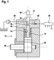
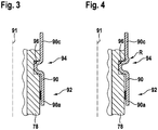
- FIG. 1 Show it Figure 1 a schematic longitudinal section through a high pressure pump, Figure 2 in an enlarged view an in Figure 1 Section marked II with the inlet valve of the high pressure pump, Figure 3 in a further enlarged view an in Figure 2 with III designated section with connection areas of a connecting element and Figure 4 a variant of the connecting element.
- a high-pressure pump is shown in detail, which is provided for pumping fuel in a fuel injection system of an internal combustion engine.
- the high-pressure pump has at least one pump element 10, which in turn has a pump piston 12, which is driven in a lifting movement by a drive, is guided in a cylinder bore 14 of a housing part 16 of the high-pressure pump and delimits a pump working space 18 in the cylinder bore 14.
- a drive shaft 20 with a cam 22 or eccentric, on which the pump piston 12 is supported directly or via a tappet, for example a roller tappet, can be provided as the drive for the pump piston 12.
- the pump working chamber 18 can be connected to a fuel inlet 26 via an inlet valve 24 and to an accumulator 30 via an outlet valve 28.
- the pump working chamber 18 can be filled with fuel with the inlet valve 24 open.
- this fuel is displaced from the pump working chamber 18 and delivered into the reservoir 30.
- the inlet valve 24 has a piston-shaped valve member 34 which has a shaft 36 which is guided displaceably in the through-bore 32 and a head 38 which is larger in diameter than the shaft 36 and which is arranged in the pump working chamber 18.
- a valve seat 40 is formed on the housing part 16, with which the valve member 34 interacts with a sealing surface 42 formed on its head 38.
- the through bore 32 has a larger diameter than in its section guiding the shaft 36 of the valve member 34, so that an annular space 44 surrounding the shaft 36 of the valve member 34 is formed.
- One or more inlet bores 46 which, on the other hand, open on the outside of the housing part 16, open into the annular space 44.
- the shaft 36 of the valve member 34 protrudes from the through-hole 32 on the side of the housing part 16 facing away from the pump working space 18, and a support element 48 is fastened to it.
- a valve spring 50 is supported on the support element 48 and, on the other hand, is supported on a region 52 of the housing part 16 surrounding the shaft 36 of the valve member 34.
- the valve spring 50 acts on the valve member 34 in an actuating direction A in its closing direction, the valve member 34 in its closed position resting with its sealing surface 42 on the valve seat 40.
- the valve spring 50 is designed, for example, as a helical compression spring.
- the inlet valve 24 can be actuated by an electromagnetic actuator 60, which in particular is shown in FIG Figure 2 is shown.
- the actuator 60 is controlled by an electronic control device 62 as a function of operating parameters of the internal combustion engine to be supplied.
- the electromagnetic actuator 60 has a magnet coil 64, a magnet core 66 and a magnet armature 68.
- the electromagnetic actuator 60 is arranged on the side of the inlet valve 24 facing away from the pump working chamber 18.
- the magnetic core 66 and the magnetic coil 64 are arranged in an actuator housing 70 which is attached to the housing part 16 of the High pressure pump can be fastened.
- the actuator housing 70 can be fastened to the housing part 16, for example, by means of a screw ring 72 that extends over it and is screwed onto a collar 74 of the housing part 16 that is provided with an external thread.
- the magnet armature 68 is at least essentially cylindrical and is guided displaceably via its outer jacket in a bore 76 in a carrier element 78 arranged in the actuator housing 70.
- the bore 76 in the carrier element 78 runs at least approximately coaxially to the through bore 32 in the housing part 16 and thus to the valve member 34.
- the carrier element 78 has a cylindrical outer shape in its end region 79 facing away from the housing part 16.
- the magnetic core 66 is arranged in the actuator housing 70 on the side of the carrier element 78 facing away from the housing part 16 and has a cylindrical outer shape.
- the magnet armature 68 has a central bore 80 arranged at least approximately coaxially to the longitudinal axis 69 of the magnet armature 68, into which a return spring 82, which is arranged on the side of the magnet armature 68 facing away from the valve member 34 and is supported on the magnet armature 68, protrudes.
- the restoring spring 82 is supported at its other end at least indirectly on the magnet core 66, which has a central bore 84 into which the restoring spring 82 projects.
- a support element 85 for the return spring 82 can be inserted, for example, pressed into the bore 84 of the magnet armature 66.
- An intermediate element 86 which can be designed as an anchor bolt, is inserted into the central bore 80 of the magnet armature 68.
- the armature bolt 86 is preferably pressed into the bore 80 of the magnet armature 68.
- the return spring 80 can also be supported in the bore 78 on the anchor bolt 86.
- the magnet armature 68
- An annular shoulder 88 is formed in the bore 76 by a diameter reduction between the magnet armature 68 and the inlet valve 24, by means of which the movement of the magnet armature 68 towards the inlet valve 24 is limited. If the actuator housing 70 is not yet attached to the housing part 16 of the high-pressure pump, the magnet armature 68 is secured against falling out of the bore 76 by the annular shoulder 88. A disk 89 can be arranged between the annular shoulder 88 and the magnet armature 68.
- the carrier element 78 and the magnetic core 66 are connected to one another by means of a sleeve-shaped connecting element 90.
- the connecting element 90 is arranged with its one axial end region 90a on the cylindrical section 79 of the carrier element 78 and connected to it and with its other axial end region 90b is arranged on the cylindrical magnet core 66 and connected to it.
- the connecting element 90 is connected neither to the carrier element 78 nor to the magnetic core 66 and bridges an axial distance between the carrier element 78 and the magnetic core 66.
- connection of the connecting element 90 to the carrier element 78 and / or to the magnetic core 66 comprises as in FIG Figure 3 each shows two connection areas 92 and 94 offset from one another in the direction of the longitudinal axis 91 of the connecting element 90.
- the connecting element 90 is firmly connected to the carrier element 78 and / or to the magnetic core 66.
- the material connection in the first connection area 92 can in particular be a welded connection.
- the welded connection in the first connection area 92 is preferably designed to be completely closed over the circumference of the connection element 90, so that it ensures that the transition between the carrier element 78 and the magnetic core 66 is sealed.
- connection element 90 is connected to the carrier element 78 and / or to the magnetic core 66 in a form-fitting manner.
- the carrier element 78 and / or the magnetic core 66 has a recess 96 in its outer jacket, which is designed in particular as a bead extending over the circumference of the carrier element 78 and / or the magnetic core 66.
- the connecting element 90 is pressed into the recess 96 with plastic deformation.
- a stamping or pressing tool can be used, by means of which the connecting element 90 is pressed radially to its longitudinal axis 91.
- the recess 96 can at its edges on the outer jacket of the carrier element 78 and / or of the magnetic core 66 can be relatively sharp-edged in order to enable a secure form fit of the connecting element 90.
- connection element 90 in the second connection area 94 reduces the load on the material connection of the connection element 90 in the first connection area 92, since part of the forces occurring in the direction of the longitudinal axis 91 of the connection element 90 are absorbed in the second connection area 94.
- connection of the connecting element 90 to the carrier element 78 is shown, with the connecting element 90 being connected to the magnetic core 66 as an alternative or in addition.
- the connecting element 90 when connecting the connecting element 90 to the carrier element 78 and the magnetic core 66, the material connection, for example in the form of the welded connection, is first made in the first connecting region 92. Subsequently, the connecting element 90 is pretensioned by applying a tensile force in the direction of its longitudinal axis 91 and in this pretensioned state the plastic deformation of the connecting element 90 into the recess 96 takes place in order to establish the positive connection in the second connection area 94. The tensile force is then removed again, wherein a prestress in the connecting element 90 is maintained between the first connecting area 92 and the second connecting area 94. As a result of this pretensioning, it can be achieved that for the first connection area 92 with the material connection there is only an increasing load during operation and no changing load, as would be the case without pretensioning.
- the connecting element 90 is elastically deformable in sections in the direction of its longitudinal axis 91.
- An elastic deformability of the connecting element 90 can, for example, as in FIG Figure 4 can be achieved in that in the second connection area 94 during the plastic deformation of the connection element 90 into the recess 96 by the stamping or pressing tool, a curvature of the connection element 90, for example with a radius R, at the transition of the recess 96 to the outer jacket of the carrier element 78 and / or the magnetic core 66 is generated. Due to the curvature, the connecting element 90 points adjacent to the second connection area 94 on a section in which this is elastically deformable in the direction of its longitudinal axis 91.
- the inlet valve 24 is open in that its valve member 34 is in its open position, in which the latter is arranged with its sealing surface 42 away from the valve seat 40.
- the movement of the valve member 34 into its open position is brought about by the pressure difference prevailing between the fuel inlet 26 and the pump working chamber 18 against the force of the valve spring 50.
- the magnetic coil 64 of the actuator 60 can be energized or de-energized. When the magnet coil 64 is energized, the magnet armature 68 is drawn towards the magnet core 66 against the force of the return spring 80 by the magnetic field that is generated.
- the armature 68 When the solenoid 64 is not energized, the armature 68 is pressed towards the inlet valve 24 by the force of the return spring 82. The magnet armature 68 rests against the end face of the shaft 36 of the valve member 34 via the armature bolt 86.
- the actuator 60 determines whether the valve member 34 of the inlet valve 24 is in its open or closed position.
- the magnet coil 64 is de-energized, the magnet armature 68 is pressed by the return spring 82 in the actuating direction according to arrow B in FIG. 2, the valve member 34 being pressed by the magnet armature 68 against the valve spring 50 in the actuating direction B into its open position.
- the force of the return spring 82 acting on the magnet armature 68 is greater than the force of the valve spring 50 acting on the valve member 34.
- the magnet armature 68 acts on the valve member 34 and the magnet armature 68 and the valve member 34 are moved together in the actuating direction B. emotional.
- the magnet coil 64 is energized so that the magnet armature 68 moves towards the magnet core 66 in an adjustment direction opposite to the adjustment direction B according to arrow A in FIG Figure 2 is pulled.
- the magnet armature 68 thus no longer exerts any force on the valve member 34, the magnet armature 68 is moved by the magnetic field in the actuating direction A and the valve member 34 is moved independently of the magnet armature 68 due to the valve spring 50 and the pressure difference between the pump working chamber 18 and the fuel inlet 26 in the actuating direction A into its closed position.
- the delivery rate of the high-pressure pump into the reservoir 30 can be set variably. If a small amount of fuel is required, the inlet valve 34 is kept open by the actuator 60 during a large part of the delivery stroke of the pump piston 12 and if a large amount of fuel is required, the inlet valve 34 is only open during a small part or not at all during the delivery stroke of the pump piston 12 held open.
Landscapes
- Engineering & Computer Science (AREA)
- Mechanical Engineering (AREA)
- General Engineering & Computer Science (AREA)
- Chemical & Material Sciences (AREA)
- Combustion & Propulsion (AREA)
- Physics & Mathematics (AREA)
- Electromagnetism (AREA)
- Power Engineering (AREA)
- Fuel-Injection Apparatus (AREA)
Claims (8)
- Soupape d'admission à actionnement électromagnétique (24) pour une pompe haute pression, en particulier d'un système d'injection de carburant, avec un organe de soupape (34) qui peut être déplacé entre une position d'ouverture et une position de fermeture, avec un actionneur électromagnétique (60) qui permet de déplacer l'organe de soupape (34), l'actionneur électromagnétique (60) présentant un induit magnétique (68) agissant au moins indirectement sur l'organe de soupape (34), une bobine magnétique (64) entourant l'induit magnétique (68) et un noyau magnétique (66) contre lequel l'induit magnétique (68) vient en butée au moins indirectement en cas de mise sous tension de la bobine magnétique (64), l'induit magnétique (68) étant guidé de manière coulissante dans un élément de support (78), et l'élément de support (78) et le noyau magnétique (66) étant reliés l'un à l'autre,
caractérisée en ce que l'élément de support (78) et le noyau magnétique (66) sont reliés l'un à l'autre par un élément de liaison (90) en forme de douille qui est relié par liaison de matière à l'élément de support (78) et/ou au noyau magnétique (66) dans respectivement une première zone de liaison (92), et est relié par complémentarité de forme dans respectivement une deuxième zone de liaison (94) disposée de manière décalée par rapport à la première zone de liaison (92) respective en direction de l'axe longitudinal (91) de l'élément de liaison (90). - Soupape d'admission selon la revendication 1, caractérisée en ce que la première zone de liaison (92) est disposée dans une zone d'extrémité de l'élément de liaison (90), vue dans la direction de l'axe longitudinal (91), et en ce que la deuxième zone de liaison (94) est disposée de manière décalée vers le centre de l'élément de liaison (90) par rapport à la première zone de liaison (92).
- Soupape d'admission selon la revendication 1 ou 2, caractérisée en ce que l'élément de support (78) et/ou le noyau magnétique (66) présente dans son enveloppe extérieure au moins un creux (96) dans lequel l'élément de liaison (90) entre par déformation plastique pour une liaison par complémentarité de forme.
- Soupape d'admission selon la revendication 3, caractérisée en ce que le creux (96) est réalisé sous la forme d'une moulure périphérique.
- Soupape d'admission selon l'une quelconque des revendications 1 à 4, caractérisée en ce que l'élément de liaison (90) présente une précontrainte en direction de son axe longitudinal (91) entre la première zone de liaison (92) et la deuxième zone de liaison (94).
- Soupape d'admission selon l'une quelconque des revendications 1 à 5, caractérisée en ce que l'élément de liaison (90) est élastiquement déformable en direction de son axe longitudinal (91), dans une partie adjacente à la deuxième zone de liaison (94).
- Soupape d'admission selon l'une quelconque des revendications précédentes, caractérisée en ce que la liaison par liaison de matière de l'élément de liaison (90) avec l'élément de support (78) et/ou le noyau magnétique (66) dans la première zone de liaison (92) est une liaison soudée.
- Pompe haute pression, en particulier pompe à carburant haute pression, comprenant au moins un élément de pompe (10) qui présente un piston de pompe (12) délimitant un espace de travail de pompe (18), l'espace de travail de pompe (18) pouvant être relié à une arrivée (26) par une soupape d'admission (24), caractérisée en ce que la soupape d'admission (24) est réalisée selon l'une quelconque des revendications précédentes.
Applications Claiming Priority (2)
| Application Number | Priority Date | Filing Date | Title |
|---|---|---|---|
| DE102015224421.0A DE102015224421A1 (de) | 2015-12-07 | 2015-12-07 | Elektromagnetisch betätigbares Einlassventil und Hochdruckpumpe mit Einlassventil |
| PCT/EP2016/076188 WO2017097498A1 (fr) | 2015-12-07 | 2016-10-31 | Soupape d'admission à commande électromagnétique et pompe haute pression munie d'une soupape d'admission |
Publications (2)
| Publication Number | Publication Date |
|---|---|
| EP3387247A1 EP3387247A1 (fr) | 2018-10-17 |
| EP3387247B1 true EP3387247B1 (fr) | 2021-05-05 |
Family
ID=57209493
Family Applications (1)
| Application Number | Title | Priority Date | Filing Date |
|---|---|---|---|
| EP16788133.3A Active EP3387247B1 (fr) | 2015-12-07 | 2016-10-31 | Soupape d'admission à commande électromagnétique et pompe haute pression munie d'une soupape d'admission |
Country Status (6)
| Country | Link |
|---|---|
| US (1) | US10851750B2 (fr) |
| EP (1) | EP3387247B1 (fr) |
| KR (1) | KR20180091027A (fr) |
| CN (1) | CN108368810B (fr) |
| DE (1) | DE102015224421A1 (fr) |
| WO (1) | WO2017097498A1 (fr) |
Families Citing this family (3)
| Publication number | Priority date | Publication date | Assignee | Title |
|---|---|---|---|---|
| GB2564703A (en) * | 2017-07-21 | 2019-01-23 | Weir Group Ip Ltd | Valve |
| ES3045882T3 (en) | 2019-05-30 | 2025-12-01 | Motor Components Llc | Fuel pump |
| CN117255893A (zh) | 2021-05-04 | 2023-12-19 | 康明斯有限公司 | 具有筒引导特征的泵总成 |
Family Cites Families (38)
| Publication number | Priority date | Publication date | Assignee | Title |
|---|---|---|---|---|
| US2574762A (en) * | 1948-06-26 | 1951-11-13 | Penn Electric Switch Co | Solenoid valve |
| US3379214A (en) * | 1965-01-15 | 1968-04-23 | Skinner Prec Ind Inc | Permanent magnet valve assembly |
| US4538129A (en) * | 1981-05-18 | 1985-08-27 | Fisher Richard T | Magnetic flux-shifting actuator |
| US7126341B2 (en) | 1997-11-03 | 2006-10-24 | Midtronics, Inc. | Automotive vehicle electrical system diagnostic device |
| WO1999044872A1 (fr) * | 1998-03-03 | 1999-09-10 | Continental Teves Ag & Co. Ohg | Electrovanne |
| WO2001014776A1 (fr) * | 1999-08-25 | 2001-03-01 | Continental Teves Ag & Co. Ohg | Soupape electromagnetique |
| WO2001036242A1 (fr) * | 1999-11-16 | 2001-05-25 | Continental Teves Ag & Co. Ohg | Vanne electromagnetique |
| DE10016600A1 (de) * | 1999-11-16 | 2001-05-17 | Continental Teves Ag & Co Ohg | Elektromagnetventil |
| DE10252231A1 (de) * | 2002-04-26 | 2003-11-06 | Continental Teves Ag & Co Ohg | Elektromagnetventil, insbesondere für schlupfgeregelte Kraftfahrzeugbremsanlagen |
| EP1503926A1 (fr) * | 2002-05-02 | 2005-02-09 | Continental Teves AG & Co. oHG | Soupape electromagnetique |
| EP1636518A2 (fr) * | 2002-12-13 | 2006-03-22 | Continental Teves AG & Co. oHG | Soupape electromagnetique |
| DE10320592A1 (de) * | 2003-05-08 | 2004-11-25 | Robert Bosch Gmbh | Förderpumpe, insbesondere Hochdruck-Kraftstoffpumpe für eine Brennkraftmaschine |
| DE10358913A1 (de) * | 2003-12-16 | 2005-09-01 | Robert Bosch Gmbh | Brennstoffeinspritzventil |
| DE102004001565A1 (de) * | 2004-01-10 | 2005-08-04 | Robert Bosch Gmbh | Elektromagnetisches Ventil, insbesondere für eine Bremsanlage eines Kraftfahrzeugs |
| DE102004004708B3 (de) * | 2004-01-30 | 2005-04-21 | Karl Dungs Gmbh & Co. Kg | Magnetventil |
| DE102006019464A1 (de) * | 2006-03-21 | 2007-09-27 | Continental Teves Ag & Co. Ohg | Elektromagnetventil |
| DE102007037220A1 (de) * | 2007-08-07 | 2009-02-12 | Robert Bosch Gmbh | Magnetventil |
| DE102007053134A1 (de) * | 2007-11-08 | 2009-05-14 | Robert Bosch Gmbh | Ventilpatrone für ein Magnetventil und zugehöriges Magnetventil |
| DE102008039959A1 (de) * | 2007-11-19 | 2009-05-20 | Continental Teves Ag & Co. Ohg | Druckregelventil |
| DE102008035332A1 (de) * | 2008-07-29 | 2010-02-04 | Robert Bosch Gmbh | Hubmagnetanordnung und Ventilanordnung |
| DE102008042731A1 (de) * | 2008-10-10 | 2010-04-15 | Robert Bosch Gmbh | Magnetventil |
| DE102009055339A1 (de) * | 2009-12-28 | 2011-06-30 | Robert Bosch GmbH, 70469 | Magnetventil |
| DE102010002224A1 (de) * | 2010-02-23 | 2011-08-25 | Robert Bosch GmbH, 70469 | Magnetventil zum Steuern eines Fluids |
| DE102010002229B4 (de) * | 2010-02-23 | 2022-07-21 | Robert Bosch Gmbh | Magnetventil zum Steuern eines Fluids |
| DE102010002216B4 (de) * | 2010-02-23 | 2022-06-30 | Robert Bosch Gmbh | Magnetventil mit Tauchstufe zum Steuern eines Fluids |
| DE102011076784B4 (de) * | 2011-05-31 | 2015-07-30 | Continental Automotive Gmbh | Einlassventil für eine Fluidpumpe und Montageverfahren für ein Einlassventil für eine Fluidpumpe |
| US8471589B2 (en) | 2011-06-16 | 2013-06-25 | GM Global Technology Operations LLC | Method and apparatus for alternator stator turn-to-turn short detection |
| DE102011090006B4 (de) * | 2011-12-28 | 2015-03-26 | Continental Automotive Gmbh | Ventil |
| DE102012205503A1 (de) * | 2012-04-04 | 2013-10-10 | Continental Teves Ag & Co. Ohg | Elektromagnetventil, insbesondere für schlupfgeregelte Kraftfahrzeugbremsanlagen |
| DE102012214920A1 (de) * | 2012-08-22 | 2014-02-27 | Continental Automotive Gmbh | Dämpfungsoberfläche an Ventilkomponenten |
| DE102012218593A1 (de) * | 2012-10-12 | 2014-04-17 | Continental Automotive Gmbh | Ventil für eine Pumpe |
| DE102013220593A1 (de) | 2013-10-11 | 2015-04-16 | Robert Bosch Gmbh | Elektromagnetisch ansteuerbares Saugventil |
| US9377124B2 (en) * | 2013-10-15 | 2016-06-28 | Continental Automotive Systems, Inc. | Normally low solenoid valve assembly |
| DE102014200339A1 (de) * | 2014-01-10 | 2015-07-16 | Robert Bosch Gmbh | Elektromagnetisch ansteuerbares Saugventil |
| DE102014202334A1 (de) * | 2014-02-10 | 2015-08-13 | Robert Bosch Gmbh | Hochdruckpumpe für ein Kraftstoffeinspritzsystem |
| DE102014220757A1 (de) * | 2014-10-14 | 2016-04-14 | Robert Bosch Gmbh | Elektromagnetisch betätigbares Saugventil, Hochdruckpumpe mit einem solchen Saugventil sowie Verfahren zur Verbindung eines solchen Saugventils mit einem Gehäuseteil einer Hochdruckpumpe |
| DE102015212387A1 (de) * | 2015-07-02 | 2017-01-05 | Robert Bosch Gmbh | Elektromagnetisch betätigbares Saugventil für eine Hochdruckpumpe sowie Verfahren zur Herstellung eines solchen Saugventils |
| DE102015222091A1 (de) * | 2015-11-10 | 2017-05-11 | Robert Bosch Gmbh | Elektromagnetisch ansteuerbares Saugventil für eine Hochdruckpumpe, Hochdruckpumpe |
-
2015
- 2015-12-07 DE DE102015224421.0A patent/DE102015224421A1/de not_active Withdrawn
-
2016
- 2016-10-31 US US16/060,293 patent/US10851750B2/en active Active
- 2016-10-31 CN CN201680071587.2A patent/CN108368810B/zh active Active
- 2016-10-31 WO PCT/EP2016/076188 patent/WO2017097498A1/fr not_active Ceased
- 2016-10-31 EP EP16788133.3A patent/EP3387247B1/fr active Active
- 2016-10-31 KR KR1020187018769A patent/KR20180091027A/ko not_active Withdrawn
Also Published As
| Publication number | Publication date |
|---|---|
| US10851750B2 (en) | 2020-12-01 |
| WO2017097498A1 (fr) | 2017-06-15 |
| KR20180091027A (ko) | 2018-08-14 |
| DE102015224421A1 (de) | 2017-06-08 |
| CN108368810A (zh) | 2018-08-03 |
| CN108368810B (zh) | 2020-11-03 |
| EP3387247A1 (fr) | 2018-10-17 |
| US20180355830A1 (en) | 2018-12-13 |
Similar Documents
| Publication | Publication Date | Title |
|---|---|---|
| WO2017144185A1 (fr) | Soupape d'admission à commande électromagnétique et pompe haute pression munie d'une soupape d'admission | |
| EP3529486A1 (fr) | Soupape d'admission à commande électromagnétique et pompe haute pression munie d'une soupape d'admission | |
| WO2015106935A1 (fr) | Pompe à haute pression munie d'une soupape d'aspiration électromagnétique | |
| WO2017097498A1 (fr) | Soupape d'admission à commande électromagnétique et pompe haute pression munie d'une soupape d'admission | |
| WO2018028865A1 (fr) | Soupape d'aspiration à actionnement électromagnétique et pompe à carburant haute pression | |
| WO2018001626A1 (fr) | Soupape d'admission à commande électromagnétique et pompe haute pression munie d'une soupape d'admission | |
| EP3380715B1 (fr) | Injecteur de carburant | |
| WO2017108343A1 (fr) | Soupape d'admission à commande électromagnétique et pompe haute pression munie d'une soupape d'admission | |
| WO2019233662A1 (fr) | Soupape d'aspiration à commande électromagnétique et pompe à carburant haute pression | |
| DE102016224722A1 (de) | Elektromagnetisch betätigbares Einlassventil und Hochdruckpumpe mit Einlassventil | |
| EP3365551B1 (fr) | Soupape d'admission à commande électromagnétique et pompe haute pression munie d'une soupape d'admission | |
| EP3423717B1 (fr) | Soupape d'admission à commande électromagnétique et pompe haute pression munie d'une soupape d'admission | |
| WO2017050463A1 (fr) | Soupape d'admission à commande électromagnétique et pompe haute pression munie d'une soupape d'admission | |
| DE102017202305A1 (de) | Elektromagnetisch betätigbares Einlassventil und Hochdruckpumpe mit Einlassventil | |
| DE102016220360B4 (de) | Pumpe, insbesondere Kraftstoffhochdruckpumpe | |
| DE102014211469A1 (de) | Düsenbaugruppe für einen Kraftstoffinjektor sowie Kraftstoffinjektor | |
| DE102015220597A1 (de) | Ventil, insbesondere Saugventil, in einer Hochdruckpumpe eines Kraftstoffeinspritzsystems | |
| DE102020209574A1 (de) | Elektromagnetisch betätigbares Einlassventil und Hochdruckpumpe mit Einlassventil | |
| DE102018208086A1 (de) | Elektromagnetisch betätigbares Einlassventil und Hochdruckpumpe mit Einlassventil | |
| DE102016224050A1 (de) | Elektromagnetisch betätigbares Einlassventil und Hochdruckpumpe mit Einlassventil | |
| DE102017201803A1 (de) | Elektromagnetisch betätigbares Einlassventil und Hochdruckpumpe mit Einlassventil | |
| WO2020083550A1 (fr) | Soupape d'admission à commande électromagnétique et pompe haute pression munie d'une soupape d'admission | |
| WO2019197067A1 (fr) | Soupape d'admission à commande électromagnétique et pompe haute pression munie d'une soupape d'admission | |
| DE102016223960A1 (de) | Elektromagnetisch betätigbares Einlassventil und Hochdruckpumpe mit Einlassventil | |
| DE102015226235A1 (de) | Elektromagnetisch betätigbares Einlassventil und Hochdruckpumpe mit Einlassventil |
Legal Events
| Date | Code | Title | Description |
|---|---|---|---|
| STAA | Information on the status of an ep patent application or granted ep patent |
Free format text: STATUS: UNKNOWN |
|
| STAA | Information on the status of an ep patent application or granted ep patent |
Free format text: STATUS: THE INTERNATIONAL PUBLICATION HAS BEEN MADE |
|
| PUAI | Public reference made under article 153(3) epc to a published international application that has entered the european phase |
Free format text: ORIGINAL CODE: 0009012 |
|
| STAA | Information on the status of an ep patent application or granted ep patent |
Free format text: STATUS: REQUEST FOR EXAMINATION WAS MADE |
|
| 17P | Request for examination filed |
Effective date: 20180709 |
|
| AK | Designated contracting states |
Kind code of ref document: A1 Designated state(s): AL AT BE BG CH CY CZ DE DK EE ES FI FR GB GR HR HU IE IS IT LI LT LU LV MC MK MT NL NO PL PT RO RS SE SI SK SM TR |
|
| AX | Request for extension of the european patent |
Extension state: BA ME |
|
| DAV | Request for validation of the european patent (deleted) | ||
| DAX | Request for extension of the european patent (deleted) | ||
| RAP1 | Party data changed (applicant data changed or rights of an application transferred) |
Owner name: ROBERT BOSCH GMBH |
|
| GRAP | Despatch of communication of intention to grant a patent |
Free format text: ORIGINAL CODE: EPIDOSNIGR1 |
|
| STAA | Information on the status of an ep patent application or granted ep patent |
Free format text: STATUS: GRANT OF PATENT IS INTENDED |
|
| INTG | Intention to grant announced |
Effective date: 20210126 |
|
| GRAS | Grant fee paid |
Free format text: ORIGINAL CODE: EPIDOSNIGR3 |
|
| GRAA | (expected) grant |
Free format text: ORIGINAL CODE: 0009210 |
|
| STAA | Information on the status of an ep patent application or granted ep patent |
Free format text: STATUS: THE PATENT HAS BEEN GRANTED |
|
| AK | Designated contracting states |
Kind code of ref document: B1 Designated state(s): AL AT BE BG CH CY CZ DE DK EE ES FI FR GB GR HR HU IE IS IT LI LT LU LV MC MK MT NL NO PL PT RO RS SE SI SK SM TR |
|
| REG | Reference to a national code |
Ref country code: GB Ref legal event code: FG4D Free format text: NOT ENGLISH |
|
| REG | Reference to a national code |
Ref country code: CH Ref legal event code: EP |
|
| REG | Reference to a national code |
Ref country code: AT Ref legal event code: REF Ref document number: 1390105 Country of ref document: AT Kind code of ref document: T Effective date: 20210515 |
|
| REG | Reference to a national code |
Ref country code: IE Ref legal event code: FG4D Free format text: LANGUAGE OF EP DOCUMENT: GERMAN |
|
| REG | Reference to a national code |
Ref country code: DE Ref legal event code: R096 Ref document number: 502016013003 Country of ref document: DE |
|
| REG | Reference to a national code |
Ref country code: LT Ref legal event code: MG9D |
|
| PG25 | Lapsed in a contracting state [announced via postgrant information from national office to epo] |
Ref country code: BG Free format text: LAPSE BECAUSE OF FAILURE TO SUBMIT A TRANSLATION OF THE DESCRIPTION OR TO PAY THE FEE WITHIN THE PRESCRIBED TIME-LIMIT Effective date: 20210805 Ref country code: HR Free format text: LAPSE BECAUSE OF FAILURE TO SUBMIT A TRANSLATION OF THE DESCRIPTION OR TO PAY THE FEE WITHIN THE PRESCRIBED TIME-LIMIT Effective date: 20210505 Ref country code: FI Free format text: LAPSE BECAUSE OF FAILURE TO SUBMIT A TRANSLATION OF THE DESCRIPTION OR TO PAY THE FEE WITHIN THE PRESCRIBED TIME-LIMIT Effective date: 20210505 Ref country code: LT Free format text: LAPSE BECAUSE OF FAILURE TO SUBMIT A TRANSLATION OF THE DESCRIPTION OR TO PAY THE FEE WITHIN THE PRESCRIBED TIME-LIMIT Effective date: 20210505 |
|
| PG25 | Lapsed in a contracting state [announced via postgrant information from national office to epo] |
Ref country code: PT Free format text: LAPSE BECAUSE OF FAILURE TO SUBMIT A TRANSLATION OF THE DESCRIPTION OR TO PAY THE FEE WITHIN THE PRESCRIBED TIME-LIMIT Effective date: 20210906 Ref country code: NO Free format text: LAPSE BECAUSE OF FAILURE TO SUBMIT A TRANSLATION OF THE DESCRIPTION OR TO PAY THE FEE WITHIN THE PRESCRIBED TIME-LIMIT Effective date: 20210805 Ref country code: PL Free format text: LAPSE BECAUSE OF FAILURE TO SUBMIT A TRANSLATION OF THE DESCRIPTION OR TO PAY THE FEE WITHIN THE PRESCRIBED TIME-LIMIT Effective date: 20210505 Ref country code: RS Free format text: LAPSE BECAUSE OF FAILURE TO SUBMIT A TRANSLATION OF THE DESCRIPTION OR TO PAY THE FEE WITHIN THE PRESCRIBED TIME-LIMIT Effective date: 20210505 Ref country code: SE Free format text: LAPSE BECAUSE OF FAILURE TO SUBMIT A TRANSLATION OF THE DESCRIPTION OR TO PAY THE FEE WITHIN THE PRESCRIBED TIME-LIMIT Effective date: 20210505 Ref country code: IS Free format text: LAPSE BECAUSE OF FAILURE TO SUBMIT A TRANSLATION OF THE DESCRIPTION OR TO PAY THE FEE WITHIN THE PRESCRIBED TIME-LIMIT Effective date: 20210905 Ref country code: GR Free format text: LAPSE BECAUSE OF FAILURE TO SUBMIT A TRANSLATION OF THE DESCRIPTION OR TO PAY THE FEE WITHIN THE PRESCRIBED TIME-LIMIT Effective date: 20210806 Ref country code: LV Free format text: LAPSE BECAUSE OF FAILURE TO SUBMIT A TRANSLATION OF THE DESCRIPTION OR TO PAY THE FEE WITHIN THE PRESCRIBED TIME-LIMIT Effective date: 20210505 |
|
| REG | Reference to a national code |
Ref country code: NL Ref legal event code: MP Effective date: 20210505 |
|
| PG25 | Lapsed in a contracting state [announced via postgrant information from national office to epo] |
Ref country code: NL Free format text: LAPSE BECAUSE OF FAILURE TO SUBMIT A TRANSLATION OF THE DESCRIPTION OR TO PAY THE FEE WITHIN THE PRESCRIBED TIME-LIMIT Effective date: 20210505 |
|
| PG25 | Lapsed in a contracting state [announced via postgrant information from national office to epo] |
Ref country code: ES Free format text: LAPSE BECAUSE OF FAILURE TO SUBMIT A TRANSLATION OF THE DESCRIPTION OR TO PAY THE FEE WITHIN THE PRESCRIBED TIME-LIMIT Effective date: 20210505 Ref country code: RO Free format text: LAPSE BECAUSE OF FAILURE TO SUBMIT A TRANSLATION OF THE DESCRIPTION OR TO PAY THE FEE WITHIN THE PRESCRIBED TIME-LIMIT Effective date: 20210505 Ref country code: CZ Free format text: LAPSE BECAUSE OF FAILURE TO SUBMIT A TRANSLATION OF THE DESCRIPTION OR TO PAY THE FEE WITHIN THE PRESCRIBED TIME-LIMIT Effective date: 20210505 Ref country code: EE Free format text: LAPSE BECAUSE OF FAILURE TO SUBMIT A TRANSLATION OF THE DESCRIPTION OR TO PAY THE FEE WITHIN THE PRESCRIBED TIME-LIMIT Effective date: 20210505 Ref country code: DK Free format text: LAPSE BECAUSE OF FAILURE TO SUBMIT A TRANSLATION OF THE DESCRIPTION OR TO PAY THE FEE WITHIN THE PRESCRIBED TIME-LIMIT Effective date: 20210505 Ref country code: SM Free format text: LAPSE BECAUSE OF FAILURE TO SUBMIT A TRANSLATION OF THE DESCRIPTION OR TO PAY THE FEE WITHIN THE PRESCRIBED TIME-LIMIT Effective date: 20210505 Ref country code: SK Free format text: LAPSE BECAUSE OF FAILURE TO SUBMIT A TRANSLATION OF THE DESCRIPTION OR TO PAY THE FEE WITHIN THE PRESCRIBED TIME-LIMIT Effective date: 20210505 |
|
| REG | Reference to a national code |
Ref country code: DE Ref legal event code: R097 Ref document number: 502016013003 Country of ref document: DE |
|
| PLBE | No opposition filed within time limit |
Free format text: ORIGINAL CODE: 0009261 |
|
| STAA | Information on the status of an ep patent application or granted ep patent |
Free format text: STATUS: NO OPPOSITION FILED WITHIN TIME LIMIT |
|
| 26N | No opposition filed |
Effective date: 20220208 |
|
| REG | Reference to a national code |
Ref country code: CH Ref legal event code: PL |
|
| PG25 | Lapsed in a contracting state [announced via postgrant information from national office to epo] |
Ref country code: IS Free format text: LAPSE BECAUSE OF FAILURE TO SUBMIT A TRANSLATION OF THE DESCRIPTION OR TO PAY THE FEE WITHIN THE PRESCRIBED TIME-LIMIT Effective date: 20210905 Ref country code: AL Free format text: LAPSE BECAUSE OF FAILURE TO SUBMIT A TRANSLATION OF THE DESCRIPTION OR TO PAY THE FEE WITHIN THE PRESCRIBED TIME-LIMIT Effective date: 20210505 |
|
| REG | Reference to a national code |
Ref country code: BE Ref legal event code: MM Effective date: 20211031 |
|
| GBPC | Gb: european patent ceased through non-payment of renewal fee |
Effective date: 20211031 |
|
| PG25 | Lapsed in a contracting state [announced via postgrant information from national office to epo] |
Ref country code: MC Free format text: LAPSE BECAUSE OF FAILURE TO SUBMIT A TRANSLATION OF THE DESCRIPTION OR TO PAY THE FEE WITHIN THE PRESCRIBED TIME-LIMIT Effective date: 20210505 |
|
| PG25 | Lapsed in a contracting state [announced via postgrant information from national office to epo] |
Ref country code: LU Free format text: LAPSE BECAUSE OF NON-PAYMENT OF DUE FEES Effective date: 20211031 Ref country code: IT Free format text: LAPSE BECAUSE OF FAILURE TO SUBMIT A TRANSLATION OF THE DESCRIPTION OR TO PAY THE FEE WITHIN THE PRESCRIBED TIME-LIMIT Effective date: 20210505 Ref country code: GB Free format text: LAPSE BECAUSE OF NON-PAYMENT OF DUE FEES Effective date: 20211031 Ref country code: BE Free format text: LAPSE BECAUSE OF NON-PAYMENT OF DUE FEES Effective date: 20211031 |
|
| PG25 | Lapsed in a contracting state [announced via postgrant information from national office to epo] |
Ref country code: LI Free format text: LAPSE BECAUSE OF NON-PAYMENT OF DUE FEES Effective date: 20211031 Ref country code: CH Free format text: LAPSE BECAUSE OF NON-PAYMENT OF DUE FEES Effective date: 20211031 |
|
| PG25 | Lapsed in a contracting state [announced via postgrant information from national office to epo] |
Ref country code: FR Free format text: LAPSE BECAUSE OF NON-PAYMENT OF DUE FEES Effective date: 20211031 |
|
| PG25 | Lapsed in a contracting state [announced via postgrant information from national office to epo] |
Ref country code: IE Free format text: LAPSE BECAUSE OF NON-PAYMENT OF DUE FEES Effective date: 20211031 |
|
| REG | Reference to a national code |
Ref country code: AT Ref legal event code: MM01 Ref document number: 1390105 Country of ref document: AT Kind code of ref document: T Effective date: 20211031 |
|
| PG25 | Lapsed in a contracting state [announced via postgrant information from national office to epo] |
Ref country code: AT Free format text: LAPSE BECAUSE OF NON-PAYMENT OF DUE FEES Effective date: 20211031 |
|
| PG25 | Lapsed in a contracting state [announced via postgrant information from national office to epo] |
Ref country code: HU Free format text: LAPSE BECAUSE OF FAILURE TO SUBMIT A TRANSLATION OF THE DESCRIPTION OR TO PAY THE FEE WITHIN THE PRESCRIBED TIME-LIMIT; INVALID AB INITIO Effective date: 20161031 |
|
| PG25 | Lapsed in a contracting state [announced via postgrant information from national office to epo] |
Ref country code: CY Free format text: LAPSE BECAUSE OF FAILURE TO SUBMIT A TRANSLATION OF THE DESCRIPTION OR TO PAY THE FEE WITHIN THE PRESCRIBED TIME-LIMIT Effective date: 20210505 |
|
| PG25 | Lapsed in a contracting state [announced via postgrant information from national office to epo] |
Ref country code: MK Free format text: LAPSE BECAUSE OF FAILURE TO SUBMIT A TRANSLATION OF THE DESCRIPTION OR TO PAY THE FEE WITHIN THE PRESCRIBED TIME-LIMIT Effective date: 20210505 |
|
| PG25 | Lapsed in a contracting state [announced via postgrant information from national office to epo] |
Ref country code: MT Free format text: LAPSE BECAUSE OF FAILURE TO SUBMIT A TRANSLATION OF THE DESCRIPTION OR TO PAY THE FEE WITHIN THE PRESCRIBED TIME-LIMIT Effective date: 20210505 |
|
| PG25 | Lapsed in a contracting state [announced via postgrant information from national office to epo] |
Ref country code: TR Free format text: LAPSE BECAUSE OF FAILURE TO SUBMIT A TRANSLATION OF THE DESCRIPTION OR TO PAY THE FEE WITHIN THE PRESCRIBED TIME-LIMIT Effective date: 20210505 |
|
| PGFP | Annual fee paid to national office [announced via postgrant information from national office to epo] |
Ref country code: DE Payment date: 20251209 Year of fee payment: 10 |