EP3387285B1 - Friction material - Google Patents
Friction material Download PDFInfo
- Publication number
- EP3387285B1 EP3387285B1 EP16873589.2A EP16873589A EP3387285B1 EP 3387285 B1 EP3387285 B1 EP 3387285B1 EP 16873589 A EP16873589 A EP 16873589A EP 3387285 B1 EP3387285 B1 EP 3387285B1
- Authority
- EP
- European Patent Office
- Prior art keywords
- friction
- particles
- friction material
- set forth
- generating layer
- Prior art date
- Legal status (The legal status is an assumption and is not a legal conclusion. Google has not performed a legal analysis and makes no representation as to the accuracy of the status listed.)
- Active
Links
Images

Classifications
-
- F—MECHANICAL ENGINEERING; LIGHTING; HEATING; WEAPONS; BLASTING
- F16—ENGINEERING ELEMENTS AND UNITS; GENERAL MEASURES FOR PRODUCING AND MAINTAINING EFFECTIVE FUNCTIONING OF MACHINES OR INSTALLATIONS; THERMAL INSULATION IN GENERAL
- F16D—COUPLINGS FOR TRANSMITTING ROTATION; CLUTCHES; BRAKES
- F16D69/00—Friction linings; Attachment thereof; Selection of coacting friction substances or surfaces
- F16D69/02—Composition of linings ; Methods of manufacturing
- F16D69/025—Compositions based on an organic binder
- F16D69/026—Compositions based on an organic binder containing fibres
-
- C—CHEMISTRY; METALLURGY
- C09—DYES; PAINTS; POLISHES; NATURAL RESINS; ADHESIVES; COMPOSITIONS NOT OTHERWISE PROVIDED FOR; APPLICATIONS OF MATERIALS NOT OTHERWISE PROVIDED FOR
- C09K—MATERIALS FOR MISCELLANEOUS APPLICATIONS, NOT PROVIDED FOR ELSEWHERE
- C09K3/00—Materials not provided for elsewhere
- C09K3/14—Anti-slip materials; Abrasives
-
- F—MECHANICAL ENGINEERING; LIGHTING; HEATING; WEAPONS; BLASTING
- F16—ENGINEERING ELEMENTS AND UNITS; GENERAL MEASURES FOR PRODUCING AND MAINTAINING EFFECTIVE FUNCTIONING OF MACHINES OR INSTALLATIONS; THERMAL INSULATION IN GENERAL
- F16D—COUPLINGS FOR TRANSMITTING ROTATION; CLUTCHES; BRAKES
- F16D13/00—Friction clutches
- F16D13/58—Details
- F16D13/60—Clutching elements
- F16D13/64—Clutch-plates; Clutch-lamellae
-
- F—MECHANICAL ENGINEERING; LIGHTING; HEATING; WEAPONS; BLASTING
- F16—ENGINEERING ELEMENTS AND UNITS; GENERAL MEASURES FOR PRODUCING AND MAINTAINING EFFECTIVE FUNCTIONING OF MACHINES OR INSTALLATIONS; THERMAL INSULATION IN GENERAL
- F16D—COUPLINGS FOR TRANSMITTING ROTATION; CLUTCHES; BRAKES
- F16D69/00—Friction linings; Attachment thereof; Selection of coacting friction substances or surfaces
- F16D69/04—Attachment of linings
-
- F—MECHANICAL ENGINEERING; LIGHTING; HEATING; WEAPONS; BLASTING
- F16—ENGINEERING ELEMENTS AND UNITS; GENERAL MEASURES FOR PRODUCING AND MAINTAINING EFFECTIVE FUNCTIONING OF MACHINES OR INSTALLATIONS; THERMAL INSULATION IN GENERAL
- F16D—COUPLINGS FOR TRANSMITTING ROTATION; CLUTCHES; BRAKES
- F16D69/00—Friction linings; Attachment thereof; Selection of coacting friction substances or surfaces
- F16D69/04—Attachment of linings
- F16D69/0408—Attachment of linings specially adapted for plane linings
-
- F—MECHANICAL ENGINEERING; LIGHTING; HEATING; WEAPONS; BLASTING
- F16—ENGINEERING ELEMENTS AND UNITS; GENERAL MEASURES FOR PRODUCING AND MAINTAINING EFFECTIVE FUNCTIONING OF MACHINES OR INSTALLATIONS; THERMAL INSULATION IN GENERAL
- F16D—COUPLINGS FOR TRANSMITTING ROTATION; CLUTCHES; BRAKES
- F16D69/00—Friction linings; Attachment thereof; Selection of coacting friction substances or surfaces
- F16D2069/005—Friction linings; Attachment thereof; Selection of coacting friction substances or surfaces having a layered structure
- F16D2069/008—Layers of fibrous materials
-
- F—MECHANICAL ENGINEERING; LIGHTING; HEATING; WEAPONS; BLASTING
- F16—ENGINEERING ELEMENTS AND UNITS; GENERAL MEASURES FOR PRODUCING AND MAINTAINING EFFECTIVE FUNCTIONING OF MACHINES OR INSTALLATIONS; THERMAL INSULATION IN GENERAL
- F16D—COUPLINGS FOR TRANSMITTING ROTATION; CLUTCHES; BRAKES
- F16D69/00—Friction linings; Attachment thereof; Selection of coacting friction substances or surfaces
- F16D69/04—Attachment of linings
- F16D2069/0425—Attachment methods or devices
- F16D2069/045—Bonding
- F16D2069/0466—Bonding chemical, e.g. using adhesives, vulcanising
-
- F—MECHANICAL ENGINEERING; LIGHTING; HEATING; WEAPONS; BLASTING
- F16—ENGINEERING ELEMENTS AND UNITS; GENERAL MEASURES FOR PRODUCING AND MAINTAINING EFFECTIVE FUNCTIONING OF MACHINES OR INSTALLATIONS; THERMAL INSULATION IN GENERAL
- F16D—COUPLINGS FOR TRANSMITTING ROTATION; CLUTCHES; BRAKES
- F16D2200/00—Materials; Production methods therefor
- F16D2200/006—Materials; Production methods therefor containing fibres or particles
- F16D2200/0069—Materials; Production methods therefor containing fibres or particles being characterised by their size
Definitions
- the subject disclosure generally relates to a friction material comprising a base and an indiscreet friction generating layer.
- the friction material can be used in a friction plate in a clutch assembly in a transmission.
- a wet clutch to facilitate the transfer of power from the vehicle's power generator (i.e. an internal combustion engine, electric motor, fuel cell, etc.) to the drive wheels.
- a transmission located downstream from the power generator and which enables vehicle launch, gear shifting, and other torque transfer events is one such component.
- Some form of a wet clutch may be found throughout many different types of transmissions currently available for motor vehicle operation.
- a wet clutch may be utilized in a torque converter for an automatic transmission, a multi-plate wet clutch pack for an automatic transmission or a semi-automatic dual-clutch transmission (DCT), and a wet start clutch that may be incorporated into a sportier automatic transmission equipped with as many as seven to nine gears as a substitute for the torque converter, to name but a few exemplary applications. Similar wet clutches may be found elsewhere in the vehicle powertrain besides the transmission.
- DCT semi-automatic dual-clutch transmission
- a wet clutch is an assembly that interlocks two or more opposed, rotating surfaces in the presence of a lubricant by imposing selective interfacial frictional engagement between those surfaces.
- a friction plate, a band, a synchronizer ring, or some other part that provides one of these engageable rotating surfaces typically supports a friction material to effectuate the intended interlocking frictional engagement.
- the presence of the lubricant at the friction interface cools and reduces wear of the friction material and permits some initial slip to occur so that torque transfer proceeds gradually, although very quickly, in an effort to avoid the discomfort that may accompany an abrupt torque transfer event (i.e., shift shock).
- Conventional friction materials generally do not function reliably in such wet clutch applications, especially the more recent clutch applications such as wet start clutch applications and shifting applications, e.g. semi-automatic DCT applications.
- COF coefficient of friction
- many of the friction materials developed only demonstrate improved COF under certain application conditions (e.g. sufficient dynamic COF) but lack the requisite COF under other application conditions (e.g. insufficient static COF).
- the friction materials developed for these wet clutch applications contribute to a variety of complications including lack of sufficient torque transfer, shuddering, and shift shock.
- a friction material comprises a base and an indiscreet friction generating layer penetrating into and integral with the base.
- the base presents a bonding surface.
- the friction generating layer presents a friction generating surface parallel to and facing opposite the bonding surface of the base.
- the friction generating layer comprises fibrillated nanofibers, friction adjusting particles, and elastomeric particles.
- a curable resin is dispersed throughout the friction generating layer and the base of the friction material. The composition of the friction generating layer provides the friction material with improved COF over a range of dynamic and static conditions.
- Figures 1-5 are exemplary in nature and are not drawn to scale and are thus not intended to represent the relative sizes of the various components of the friction material, e.g. the friction generating layer, the base, the friction generating particles, the fibrillated nanofibers, the elastomeric particles, etc.
- the friction material e.g. the friction generating layer, the base, the friction generating particles, the fibrillated nanofibers, the elastomeric particles, etc.
- a friction material is shown generally at 10 and a friction plate is shown generally at 30.
- the friction material 10 described herein is typically used on a friction plate 30 which is included in a wet clutch assembly in a transmission of a motor vehicle.
- a friction plate 30 which is included in a wet clutch assembly in a transmission of a motor vehicle.
- the friction material 10 and friction plate 30 described herein can be used in other vehicular applications and have applications beyond motor vehicles.
- the friction material 10 comprises a base 12 and an indiscreet friction generating layer 14 penetrating into and integral with the base 12.
- the friction generating layer 14 is also known in the art as a deposit layer or a deposit.
- the base 12 presents a bonding surface 16.
- the friction generating layer 14 presents a friction generating surface 18 facing opposite (and parallel to) the bonding surface 16 of the base 12.
- a curable resin 26 is dispersed throughout the friction generating layer 14 and the base 12 of the friction material 10.
- the friction material 10 has a thickness T 1 defined as a distance between the friction generating surface 18 and the bonding surface 16.
- the friction generating layer 14 extends from the friction generating surface 18 towards the bonding surface 16 up to about 40%, alternatively up to about 30%, alternatively up to about 20%, alternatively up to about 10%, alternatively up to about 5%, of the thickness T 1 .
- the base 12 typically has a thickness T 2 of less than about 2 mm, alternatively from about 0.25 mm to about 2 mm, alternatively from about 0.3 mm to about 1 mm, alternatively of from about 0.3 mm to about 0.4 mm.
- the friction generating layer 14 may extend inwards from the friction generating surface 18 to a depth up to about 0.0125 mm (5% of 0.25 mm) to about 0.80 mm (40% of 2 mm).
- the friction generating layer 14 comprises fibrillated nanofibers 20, friction adjusting particles 22, and elastomeric particles 24.
- the friction generating layer 14 may be referred to as indiscreet because the fibrillated nanofibers 20, the friction adjusting particles 22, and the elastomeric particles 24, are applied to, and typically penetrate into, the base 12. Likewise, particles and fibers of the base 12 may penetrate into the friction generating layer 14. Accordingly, the friction generating layer 14 and the base 12 are integral layers within the friction material 10.
- the friction generating layer 14 comprises, consists essentially of, or consists of, the fibrillated nanofibers 20, the friction adjusting particles 22, and the elastomeric particles 24. In some embodiments, the friction generating layer 14 comprises, consists essentially of, or consists of, a single type of the fibrillated nanofibers 20, a single type of the friction adjusting particles 22, and a single type of the elastomeric particles 24.
- consists essentially of' is used to describe embodiments that include the specified components (e.g. a friction material 10 including a friction generating layer 14 including the fibrillated nanofibers 20, the friction adjusting particles 22, and the elastomeric particles 24) which is free of, or substantially free of (e.g. includes less than 5 wt. % or less than 1 wt. %), other compounds and additives.
- specified components e.g. a friction material 10 including a friction generating layer 14 including the fibrillated nanofibers 20, the friction adjusting particles 22, and the elastomeric particles 24
- the elastomeric particles 24 of the friction generating layer 14 are particles which are elastic and exhibit rubber-like properties. Use of the elastomeric particles 24 in the friction generating layer 14 provides improved compressibility and an increased coefficient of friction over a wide range of temperatures and conditions. Suitable elastomeric particles 24 are chosen from particles derived from cashew nut shell oil, rubber, and combinations thereof.
- the elastomeric particles 24 have an elastic modulus of from about 0.01 to about 3, alternatively from about 0.01 to about 2, alternatively from about 0.02 to about 1, alternatively from about 0.03 to about 0.3, GPa.
- the elastomeric particles 24 have a compressibility of from about 1 to about 10, alternatively from about 1.5 to about 7.5, % when tested in accordance with ISO 6310.
- the elastomeric particles 24 have a first deflection (amount compressed from original diameter/thickness) of from about 0.5 to about 10, alternatively from about 1 to about 7, % of original thickness when tested in accordance with ISO 6310.
- the elastomeric particles 24 have a first hysteresis (amount of lost diameter/thickness after load removed) of from about 0.1 to about 10, alternatively from about 0.2 to about 7, % of original thickness when tested in accordance with ISO 6310.
- the elastomeric particles 24 comprise, consist essentially of, or consist of rubber.
- Rubber is a polymer that exhibits elasticity. Rubber can be a natural rubber, a modified natural rubber, or a synthetic rubber. The rubber can be defined as an elastomer or a thermoplastic elastomer.
- the elastomeric particles 24 comprise, consist essentially of, or consist of silicone rubber (including modified silicone rubber), styrene butadiene rubber (“SBR”), butyl rubber, thermoplastic elastomers (including ethylene acrylic elastomers) and halogenated rubbers such as chlorobutyl rubber, bromobutyl rubber, polychloroprene rubber, fluoro rubber (sometimes referred to as fluoroelastomer or perfluoroelastomer), and nitrile rubber (sometimes referred to as buna-N, perbunan, acrylonitrile butadiene rubber, NBR, hydrogenated NBR).
- silicone rubber including modified silicone rubber
- SBR styrene butadiene rubber
- butyl rubber thermoplastic elastomers (including ethylene acrylic elastomers) and halogenated rubbers
- chlorobutyl rubber bromobutyl rubber
- polychloroprene rubber fluoro rubber (sometimes referred to as flu
- the elastomeric particles 24 comprise, consist essentially of, or consist of fluororubber (fluoroelastomer) categorized under the ASTM D1418 & ISO 1629 designation of FKM.
- fluororubber fluoroelastomer
- This class of elastomers is a family comprising copolymers of hexafluoropropylene (HFP) and vinylidene fluoride (VDF or VF2), terpolymers of tetrafluoroethylene (TFE), vinylidene fluoride (VDF) and hexafluoropropylene (HFP) as well as perfluoromethylvinylether (PMVE) containing specialties.
- the elastomeric particles 24 comprise, consist essentially of, or consist of, silicone rubber. In other embodiments the elastomeric particles 24 comprise, consist essentially of, or consist of, nitrile rubber.
- the elastomeric particles 24 comprise, consist essentially of, or consist of, cashew nut particles or particles derived from cashew nut shell oil.
- Cashew nut particles comprise cashew nut shell liquid, which is a naturally occurring compound found in the honeycomb structure of a cashew nut shell.
- the elastomeric particles 24 comprise cashew nut particles which are brown, and in other embodiments, the elastomeric particles 24 comprise cashew nut particles which are black. In such embodiments, the particles may be screened to 100, 90, 80, 70, 60, 50, or 40, mesh.
- the elastomeric particles 24 have average diameters of less than about 40 ⁇ m, alternatively from about 2 ⁇ m to about 40 ⁇ m, alternatively from about 5 ⁇ m to about 30 ⁇ m, alternatively from about 5 ⁇ m to about 15 ⁇ m.
- elastomeric particles 24 of the friction generating layer 14 having an average diameter of less than about 40 ⁇ m typically improve the compression of the friction generating layer 14 and, importantly, when used in combination with the friction adjusting particles 22 and the fibrillated nanofibers 20 unexpectedly yield a friction generating surface 18 having an improved static COF as is explained throughout this disclosure.
- the elasticity and relative lack of rigidity provided by the particles provide a cushioning effect upon compression of the friction generating surface 18 of the friction material 10 which evenly distributes pressures at elevated temperature and, thus, improves the static COF of the friction generating surface 18 without negatively effecting the dynamic COF of the friction generating surface 18.
- the friction material 10 comprises the base 12 and the friction generating layer 14 comprising the fibrillated nanofibers 20, the friction adjusting particles 22, and the elastomeric particles 24 having an average diameter of less than about 40 ⁇ m.
- the elastomeric particles 24 having an average diameter of less than about 40 ⁇ m are included in the friction generating layer 14 in an amount sufficient to increase the static COF of the of the friction generating surface 18.
- the elastomeric particles 24 have a thermal stability of about 200°C or greater, alternatively about 250°C or greater, alternatively about 300°C or greater, alternatively about 350°C or greater.
- thermal stability it is meant that the elastomeric particles 24 do not melt, soften, or decompose.
- the thermal stability of the elastomeric particles 24 is typically determined by thermal gravimetric analysis ("TGA"). The temperature at which a test sample of the elastomeric particles 24 analyzed via TGA loses 5 wt. % based on a total weight of the test sample is the temperature at which the elastomeric particles 24 lose thermal stability.
- the elastomeric particles 24 are typically present in the friction material 10 in an amount of from about 3 to about 15 lbs per 3000 ft 2 (about 1.4 to about 6.8 kg per 278.7 m 2 ) of the friction generating surface 18, alternatively from about 6 to about 12 lbs per 3000 ft 2 (about 2.7 kg to about 5.4 kg per 278.7 m 2 ) of the friction generating surface 18, alternatively from about 8 to about 10 lbs per 3000 ft 2 (about 3.6 kg to about 4.5 kg per 278.7 m 2 ) of the friction generating surface 18, alternatively about 9 lbs per 3000 ft 2 (about 4.1 kg per 278.7 m 2 ) of the friction generating surface 18.
- the amount of the elastomeric particles 24 present in the friction generating layer 14 may vary outside of the ranges above, but is typically both whole and fractional values within these ranges. Further, it is to be appreciated that more than one type of the elastomeric particles 24 may be included in the friction generating layer 14, in which case the total amount of all the elastomeric particles 24 present in the friction generating layer 14 is within the above ranges.
- the amount of the components in the friction generating layer 14 provided herein are in units of pounds per 3000 ft 2 , such units are customarily used in the paper making industry as a measurement of weight based on a given surface area of a thin layer, whether impregnated with the curable resin 26 or not.
- the units express the weight of the elastomeric particles 24 present in the friction generating layer 14 for every 3000 ft 2 of the friction generating surface 18.
- the units express the weight of the fibrillated nanofibers 20 and the friction adjusting particles 22 present in the friction generating layer 14 for every 3000 ft 2 of the friction generating surface 18.
- the friction adjusting particles 22 of the friction generating layer 14 increase the dynamic COF of the friction generating surface 18.
- Various suitable friction adjusting particles 22 are chosen from silica, carbon, graphite, alumina, magnesia, calcium oxide, titania, ceria, zirconia, cordierite, mullite, sillimanite, spodumene, petalite, zircon, silicon carbide, titanium carbide, boron carbide, hafnium carbide, silicon nitride, titanium nitride, titanium boride, and combinations thereof.
- various suitable friction adjusting particles 22 comprise, consist essentially of, or consist of, silica, carbon, graphite, alumina, magnesia, calcium oxide, titania, ceria, zirconia, cordierite, mullite, sillimanite, spodumene, petalite, zircon, silicon carbide, titanium carbide, boron carbide, hafnium carbide, silicon nitride, titanium nitride, titanium boride, or combinations thereof.
- the friction adjusting particles 22 comprise, consist essentially of, or consist of diatomaceous earth.
- Diatomaceous earth is a mineral comprising silica.
- Diatomaceous earth is an inexpensive, abrasive material that exhibits a relatively high COF which readily disperses throughout the fibrillated nanofibers 20 of the friction generating layer 14.
- all of the friction adjusting particles 22 included in the friction generating layer 14 may be diatomaceous earth or, alternatively, the friction adjusting particles 22 may include a combination of different types of the friction adjusting particles 22, such as various combinations of diatomaceous earth, carbon, graphite, and alumina.
- the type or types of the friction adjusting particles 22 included in the friction generating layer 14 may vary depending on the friction characteristics sought at the friction generating surface 18 of the friction material 10.
- the friction adjusting particles 22 have a Mohs hardness of from about 2 to about 9, alternatively from about 3 to about 9, alternatively from about 5 to about 6.5, alternatively from about 5.5 to about 6.
- the hardness of the friction adjusting particles 22 stands in contrast to the elasticity/elastic modulus of the elastomeric particles 24 and it is believed that the disclosed combination of friction adjusting particles 22 and elastomeric particles 24 provides the friction generating layer 14 with excellent static and dynamic friction characteristics.
- the friction adjusting particles 22 have an average diameter of from about 1 ⁇ m to about 30 ⁇ m, alternatively from about 5 ⁇ m to about 16 ⁇ m. Further, in various embodiments, the friction adjusting particles 22 have a thermal stability of about 400°C or greater, alternatively 450°C or greater, alternatively 500°C or greater. By thermal stability it is meant that the friction adjusting particles 22 do not melt, soften, or decompose. The thermal stability of the friction adjusting particles 22 is typically determined by TGA. The temperature at which a test sample of the friction adjusting particles 22 analyzed via TGA loses 5 wt. % based on a total weight of the test sample is the temperature at which the friction adjusting particles 22 lose thermal stability.
- the friction adjusting particles 22 are typically present in the friction material 10 in an amount of from about 7 to about 23 lbs per 3000 ft 2 (about 3.2 to about 10.4 kg per 278.7 m 2 ) of the friction generating surface 18, alternatively from about 10 to about 20 lbs per 3000 ft 2 (about 4.5 to about 9.1 kg per 278.7 m 2 ) of the friction generating surface 18, alternatively from about 12 to about 18 lbs per 3000 ft 2 (about 5.4 to about 8.2 kg per 278.7 m 2 ) of the friction generating surface 18, alternatively about 15 lbs per 3000 ft 2 (about 6.8 kg per 278.7 m 2 ) of the friction generating surface 18.
- the amount of the friction adjusting particles 22 present in the friction generating layer 14 may vary outside of the ranges above, but is typically both whole and fractional values within these ranges. Further, it is to be appreciated that more than one type of the friction adjusting particles 22 may be included in the friction generating layer 14, in which case the total amount of all the friction adjusting particles 22 present in the friction generating layer 14 is within the above ranges.
- the friction adjusting particles 22 and the elastomeric particles 24 are present in the friction generating layer 14 in a weight ratio of from about 3:1 to about 1:1.
- the fibrillated nanofibers 20 of the friction generating layer 14 are chosen from cellulose fibers, aramid fibers, acrylic fibers, and combinations thereof.
- the fibrillated nanofibers 20 of the friction generating layer 14 comprise, consist essentially of, or consist of, cellulose fibers, aramid fibers, acrylic fibers, or combinations thereof.
- the fibrillated nanofibers 20 comprise cellulose.
- the fibrillated nanofibers 20 comprise natural cellulose, regenerated cellulose, a cellulose derivative, or a mixture thereof.
- the fibrillated nanofibers 20 comprise at least 50 wt. %, alternatively at least 60 wt. %, alternatively at least 70 wt. %, alternatively at least 80 wt. %, alternatively at least 90 wt. %, alternatively at least 99 wt. %, alternatively about 100 wt. %, of natural cellulose, regenerated cellulose, a cellulose derivative, or a mixture thereof.
- the fibrillated nanofibers 20 consist essentially of, or consist of, cellulose. In some embodiments, the fibrillated nanofibers 20 comprise, consist essentially of, or consist of natural cellulose. In other embodiments, the fibrillated nanofibers 20 comprise, consist essentially of, or consist of, regenerated cellulose. For example, in such other embodiments, the fibrillated nanofibers 20 comprise, consist essentially of, or consist of, regenerated lyocell cellulose.
- Natural cellulose is a straight chain polysaccharide that includes repeating ⁇ (1 ⁇ 4)-glycosidic-linked glucose units and which has the general polymeric formula (C 6 H 1 O 5 ) n with the number of repeating units ("n") usually ranging from 100 to 10,000.
- Regenerated cellulose has the same chemical formula as natural cellulose and is prepared from naturally-occurring polymers (e.g. wood pulp or bamboo) from one of several processes including the viscose process, the cuprammonium process, and an organic solvent spinning process. Some examples of regenerated cellulose are rayon, modal, and lyocell.
- a cellulose derivative is a modified cellulose in which the hydroxyl group on the glucose units is fully or partially substituted with, for example, an ester group. Some examples of a cellulose derivative are cellulose acetate and cellulose triacetate.
- the fibrillated nanofibers 20 comprise aramid.
- the aramid is synthetic aromatic polyamide.
- aromatic polyamide is para-aramid, such as the condensation product of 1,4-phenylene-diamine and terephthaloyl chloride.
- aromatic polyamide is meta-aramid, such as the condensation product of m-phenylenediamine and isophthaloyl chloride.
- the fibrillated nanofibers 20 comprise acrylic.
- the acrylic is a synthetic acrylic polymer formed from at least 85 wt. % acrylonitrile monomers.
- the fibrillated nanofibers 20 have average diameters of from about 20 nm to about 800 nm, alternatively from about 30 nm to about 600 nm, alternatively from about 50 nm to about 500 nm, and average lengths of from about 1 mm to about 10 mm, alternatively from about 2 mm to about 8 mm, alternatively from about 4 mm to about 6 mm.
- the fibrillated nanofibers 20 typically have a degree of fibrillation as measured according to Canadian Standard Freeness ("CSF") of from about 5 ml CSF to about 300 ml CSF, alternatively from about 10 ml CSF to about 200 ml CSF, alternatively from about 10 ml CSF to about 100 ml CSF.
- CSF is an empirical test procedure that measures the rate at which 3 grams of a fibrous pulp material in 1 liter of water may be drained. CSF measurements are conducted in accordance with the TAPPI T227 test procedure.
- the fibrillated nanofibers 20 have a thermal stability of about 200°C or greater, alternatively 250°C or greater, alternatively 350°C or greater.
- thermal stability it is meant that the fibrillated nanofibers 20 do not melt, soften, or decompose.
- the thermal stability of the fibrillated nanofibers 20 is typically determined by TGA. The temperature at which a test sample of the elastomeric particles 24 analyzed via TGA loses 5 wt. % based on a total weight of the test sample is the temperature at which the elastomeric particles 24 lose thermal stability.
- the fibrillated nanofibers 20 are typically present in the friction material 10 in an amount of from about 1 to about 6 lbs per 3000 ft 2 (about 0.5 kg to about 2.7 kg per 278.7 m 2 ) of the friction generating surface 18, alternatively from about 2 to about 5 lbs per 3000 ft 2 (about 0.9 kg to about 2.3 kg per 278.7 m 2 ) of the friction generating surface 18, alternatively from about 2 to about 4 lbs per 3000 ft 2 (about 0.9 kg to about 1.8 kg per 278.7 m 2 ) of the friction generating surface 18, alternatively about 3 lbs per 3000 ft 2 (about 1.4 kg per 278.7 m 2 ) of the friction generating surface 18.
- the amount of the fibrillated nanofibers 20 present in the friction generating layer 14 may vary outside of the ranges above, but is typically both whole and fractional values within these ranges. Further, it is to be appreciated that more than one type of the fibrillated nanofibers 20 may be included in the friction generating layer 14, in which case the total amount of all the fibrillated nanofibers 20 present in the friction generating layer 14 is within the above ranges.
- about 6 lbs to about 12 lbs of the elastomeric particles 24, about 10 lbs to about 20 lbs of the friction adjusting particles 22, and about 1 to about 7 lbs of the fibrillated nanofibers 20, each based on about 3000 ft 2 of the friction generating surface 18 are present in the friction generating layer 14.
- the amounts of the fibrillated nanofibers 20 and the friction adjusting particles 22 can be chosen to affect the frictional characteristics of the friction material 10.
- the porosity of the friction material 10 at the friction generating surface 18, for instance, is inversely proportional to the amount of the fibrillated nanofibers 20 present in the friction generating layer 14.
- the amount of the friction adjusting particles 22 present in the friction generating layer 14 influences both the static and dynamic COF that can be achieved at the friction generating surface 18. Although a higher COF generally accompanies a higher amount of friction adjusting particles 22 and vice versa, use of the friction adjusting particles 22 and the fibrillated nanofibers 20 alone does not allow for significant improvement of the static COF of the friction material 10.
- the use of the elastomeric particles 24 along with the friction adjusting particles 22 and the fibrillated nanofibers 20 in the friction generating layer 14 in the amounts disclosed herein significantly improves the dynamic and static COF of the friction material 10.
- the friction material 10 includes a friction generating layer 14 comprising: (1) fibrillated nanofibers 20 comprising cellulose and having an average length of from about 1 mm to about 10 mm and an average degree of fibrillation of from about 10 mL CSF to about 300 mL CSF as measured by Canadian Standard Freeness, wherein the fibrillated nanofibers 20 are present in the friction generating layer 14 in an amount of from about 1 to about 6 lbs per 3000 ft 2 (about 0.5 kg to about 2.7 kg per 278.7 m 2 ) of the friction generating surface 18; (2) the friction adjusting particles 22 comprising diatomaceous earth and present in the friction generating layer 14 an amount of from about 7 to about 23 lbs per 3000 ft 2 (about 3.2 to about 10.4 kg per 278.7 m 2 ); and (3) elastomeric particles 24 derived from cashew nut shell oil and having an average diameter of less than about 40 ⁇ m, the elastomeric particles 24 present in an amount of from about
- the curable resin 26 is dispersed throughout the friction generating layer 14 and the base 12 in an amount of less than about 40 wt. % based on 100 parts by weight of the friction material 10.
- the combination of the fibrillated nanofibers 20, the friction adjusting particles 22, and elastomeric particles 24 in the friction generating layer 14 not only provides the friction material 10 with an excellent dynamic and static COF, the combination advantageously allows for a reduction in the amount of curable resin 26 required, and, as is set forth below, the combination also allows for a reduction in the thickness of the base 12.
- the base 12 typically comprises various structural fibers 28 and fillers.
- the base 12 comprises the structural fibers 28 which penetrate into the friction generating layer 14 and intermingle with the fibrillated nanofibers 20.
- the base 12 can be referred to as indiscreet, just like the friction generating layer 14.
- the structural fibers 28 of the base 12 are exposed at the friction generating surface 18. In other embodiments, the structural fibers 28 of the base 12 are not exposed at the friction generating surface 18.
- the structural fibers 28 are typically chosen from cellulose fibers, aramid fibers, acrylic fibers, glass fibers, ceramic fibers, novoloid (phenol-formaldehyde) fibers, carbon fibers, mineral fibers, and combinations thereof.
- the various types of cellulose, aramid, and acrylic fibers are just as described above in reference to the fibrillated nanofibers 20 of the friction generating layer 14.
- Carbon fibers, sometimes referred to as graphite fibers, are fibers comprising carbon atoms.
- carbon fibers as discussed herein include fibers formed with carbon and other materials, i.e. composite carbon fibers.
- the structural fibers 28 have average diameters of from about 20 nm to about 2000 nm, alternatively from about 30 nm to about 1750 nm, alternatively from about 50 nm to about 1500 nm, and average lengths of from about 2 mm to about 20 mm, alternatively from about 4 mm to about 18 mm, alternatively from about 6 mm to about 16 mm.
- the structural fibers 28 typically have a degree of fibrillation as measured according to CSF of from about 100 ml CSF to about 1000 ml CSF, alternatively from about 100 ml CSF to about 800 ml CSF, alternatively from about 100 ml CSF to about 650 ml CSF.
- the base 12 includes fibrillated micro structural fibers 28 comprising aramid such as poly-paraphenylene terephthalamide.
- the base 12 includes structural fibers 28 comprising cellulose.
- the base 12 includes structural fibers 28 comprising carbon.
- the base 12 includes individual structural fibers 28 comprising, consisting of, or consisting essentially of aramid and cellulose. The combination of these two types of microfibers provides the base 12 with thermal and chemical stability and a high fatigue resistance well above 350°C.
- the aramid and cellulose structural fibers 28 present in the base 12 of this embodiment may be natural or synthetic.
- the structural fibers 28 are typically present in the friction material 10 in an amount of from about 10 to about 90 wt. %, alternatively from about 20 to about 70 wt. %, based on the total weight of the base 12.
- the amount of the structural fibers 28 present in the base 12 may vary outside of the ranges above, but is typically both whole and fractional values within these ranges. Further, it is to be appreciated that more than one type of the structural fibers 28 may be included in the base 12, in which case the total amount of all the structural fibers 28 present in the base 12 is within the above ranges.
- the fillers include chosen from silica, carbon, graphite, alumina, magnesia, calcium oxide, titania, ceria, zirconia, cordierite, mullite, sillimanite, spodumene, petalite, zircon, silicon carbide, titanium carbide, boron carbide, hafnium carbide, silicon nitride, titanium nitride, titanium boride, diatomaceous earth, cashew nut particles, and combinations thereof.
- the fillers of the base 12 comprise, consisting essentially of, or consist of, silica, carbon, graphite, alumina, magnesia, calcium oxide, titania, ceria, zirconia, cordierite, mullite, sillimanite, spodumene, petalite, zircon, silicon carbide, titanium carbide, boron carbide, hafnium carbide, silicon nitride, titanium nitride, titanium boride, diatomaceous earth, cashew nut particles, and combinations thereof.
- the filler of the base 12 includes a combination of diatomaceous earth and carbon.
- the base 12 is substantially free of the elastomeric particles 24.
- the elastomeric particles 24, such as those derived from cashew nut particles are present in the base 12 in an amount of from less than about 1, alternatively less than about 0.5, alternatively less than about 0.25, alternatively less than about 0.1, alternatively 0, wt. % based on the total weight of the base 12.
- some of the elastomeric particles 24 added to the friction generating layer 14 may intermingle with or penetrate into the base 12, but prior to application of the components of the friction generating layer 14, the base 12 is substantially free of the elastomeric particles 24.
- the filler is typically present in the friction material 10 in an amount of from about 20 to about 80 wt. %, alternatively about 20 to about 60 wt. %, based on the total weight of the base 12.
- the amount of the filler present in the base 12 may vary outside of the ranges above, but is typically both whole and fractional values within these ranges. Further, it is to be appreciated that more than one type of the filler may be included in the base 12, in which case the total amount of all the fillers present in the base 12 is within the above ranges.
- the curable resin 26 may be any thermosetting resin suitable for providing structural strength to the friction material 10.
- the curable resin 26 may, for example, be a phenolic resin or a modified phenolic resin (e.g. an epoxy phenolic, etc.)
- a phenolic resin is a class of thermosetting resins that is produced by the condensation of an aromatic alcohol, typically a phenol, and an aldehyde, typically a formaldehyde.
- a phenolic-based resin is a thermosetting resin blend that includes at least 50 wt. % of a phenolic resin based on the total weight of all resins and excluding any solvents or processing acids.
- thermosetting resins that may be blended with a phenolic resin include silicone resins, epoxy resins, and polybutadiene resins, to name but a few examples.
- the curable resin 26 is referred to as the cured resin 34, the cured resin 34 confers strength and durability to the friction material 10 and adheres the elastomeric particles 24, the fibrillated nanofibers 20, and the friction adjusting particles 22 in the friction generating layer 14 while maintaining a desired porosity for proper lubricant flow and retention.
- the curable resin 26 is present in the friction material 10 in an amount of less than about 50 wt. %, alternatively less than about 45, alternatively less than about 40, alternatively from about 20 wt. % to about 35 wt. %, alternatively from about 25 wt. % to about 30 wt. %, based on 100 parts by weight of the friction material 10.
- the combination of the elastomeric particles 24, the fibrillated nanofibers 20, and the friction adjusting particles 22 in the friction generating layer 14 allows for reduction in an amount of the curable resin 26 in the friction material 10 providing excellent performance properties (e.g. COF and wear properties).
- the friction plate 30 comprises the friction material 10, which is cured (i.e. comprising cured resin 34) bonded to a substrate 32 with a bonding adhesive 36.
- the bonding surface 16 is the surface of the friction material 10 where bonding to the substrate 32 or other material is meant to be accomplished. As such, the bonding surface 16 of the base 12 is bonded to a substrate 32.
- the friction material 10 is bonded to the substrate 32 by any suitable technique known to skilled artisans.
- the friction material 10 is bonded to the substrate 32 with the bonding adhesive 36, which is generally known to those skilled in the art, e.g. with a bonding adhesive 36 comprising phenolic modified nitrile rubber.
- Exemplary substrates 32 include, but are not limited to, friction/clutch plates, synchronizer rings, and transmission bands.
- the substrate 32 is typically metal.
- the various embodiments of the friction material 10 described herein may be used in a wet clutch.
- the friction generating surface 18 of the friction material 10 experiences interfacial frictional engagement with an opposed mating surface (not shown) in the presence of a lubricant.
- the friction generating surface 18 experiences select interfacial frictional engagement with an opposed, rotating surface (not shown) in the presence of a lubricant, and the bonding surface 16 achieves bonded attachment to the substrate 32 with the aid of an adhesive or some other suitable bonding technique.
- the lubricant may be any suitable lubricating fluid such as, for example, an automatic transmission fluid.
- friction material 10 performs satisfactorily above about 350°C, alternatively about 400°C, alternatively about 450°C, it is not limited only to such high-temperature environments and may, if desired, be used in a wet clutch designed to maintain a temperature at the friction generating surface 18 below 350°C.
- the friction material 10 can maintain a positive ⁇ -v relationship and resist glazing because its friction generating surface 18 is able to be repeatedly regenerated. Such regeneration can be attributed to the presence of the fibrillated cellulose nanofibers and their supported friction adjusting particles 22.
- the balanced content of those two materials provides enough friction adjusting particles 22 at or near the friction generating surface 18 to sustain a positive ⁇ -v relationship at elevated temperatures while permitting the fibrillated cellulose nanofibers closest to the friction generating surface 18 to thermally decompose at regular intervals.
- the combination of the fibrillated nanofibers 20, the friction adjusting particles 22, and elastomeric particles 24 in the friction generating layer 14 provides a friction material 10 with excellent dynamic and static COF, the combination advantageously allows for a reduction in the amount of curable resin 26 required, and also allows for a reduction in the thickness of the base 12, as is set forth in the Examples below.
- the elastomeric particles 24 of friction generating layer 14 and a reduced amount of curable resin 26 increase the compressibility of the friction generating layer 14.
- many such embodiments of the friction material 10 exhibit excellent dynamic and static COF as well as durability characteristics in wet clutch applications.
- Example friction materials representative of this disclosure are formed along with three comparative examples of friction materials that are not representative of this disclosure (Comparative Examples 1-3.) After formation, the Examples and the Comparative Examples are evaluated to determine a variety of performance properties.
- the compositions of Examples 1 and 2 and Comparative Examples 1-3 are set forth in Table 1 below.
- TABLE 1 Friction Material Component Example 1 Example 2 Comparative Example 1 Comparative Example 2 Comparative Example 3 Base A Structural Fibers A and B 40-60 wt. % 40-60 wt. % 40-60 wt. % 40-60 wt. % 40-60 wt. % 40-60 wt. % Fillers A and B 35-55 wt. % 35-55 wt. % 35-55 wt. % 35-55 wt.
- Structural Fibers A and B comprise aramid and natural cellulose, respectively.
- Fillers A and B comprise diatomaceous earth and graphite, respectively.
- Friction Adjusting Particle is diatomaceous earth having a Mohs hardness of from about 5.5 to about 6.
- Fibrillated Nanofiber is a lyocell cellulose fiber.
- Elastomeric Particle is a particle comprising a cashew nut shell oil derivative having a mean diameter of about 12 ⁇ m and a compressibility of from about 1.5 to 7.5%.
- Examples 1 and 2 and Comparative Examples 1-3 are cured and bonded to a metal substrate to form friction plates.
- the friction plates including the friction materials of Example 1 and Comparative Examples 1 and 2 are then tested in duplicate on a No. 2 Friction Test Machine in accordance with SAE procedure J2490 ( ⁇ PVT).
- the SAE No. 2 Friction Test Machine is used to evaluate the friction characteristics of automatic transmission plate clutches with automotive transmission fluids as well as durability tests on wet friction systems. Testing was conducted in Dual Clutch Transmission (“DCT”) fluid.
- DCT Dual Clutch Transmission
- any ranges and subranges relied upon in describing various embodiments of the present disclosure independently and collectively fall within the scope of the appended claims, and are understood to describe and contemplate all ranges including whole and/or fractional values therein, even if such values are not expressly written herein.
- One of skill in the art readily recognizes that the enumerated ranges and subranges sufficiently describe and enable various embodiments of the present disclosure, and such ranges and subranges may be further delineated into relevant halves, thirds, quarters, fifths, and so on. As just one example, a range "of from 0.1 to 0.9" may be further delineated into a lower third, i.e.
- a range of "at least 10" inherently includes a subrange of from at least 10 to 35, a subrange of from at least 10 to 25, a subrange of from 25 to 35, and so on, and each subrange may be relied upon individually and/or collectively and provides adequate support for specific embodiments within the scope of the appended claims.
- an individual number within a disclosed range may be relied upon and provides adequate support for specific embodiments within the scope of the appended claims.
- a range "of from 1 to 9" includes various individual integers, such as 3, as well as individual numbers including a decimal point (or fraction), such as 4.1, which may be relied upon and provide adequate support for specific embodiments within the scope of the appended claims.
Landscapes
- Engineering & Computer Science (AREA)
- General Engineering & Computer Science (AREA)
- Mechanical Engineering (AREA)
- Chemical & Material Sciences (AREA)
- Materials Engineering (AREA)
- Organic Chemistry (AREA)
- Mechanical Operated Clutches (AREA)
- Braking Arrangements (AREA)
Description
- The subject disclosure generally relates to a friction material comprising a base and an indiscreet friction generating layer. The friction material can be used in a friction plate in a clutch assembly in a transmission.
- Several components of a motor vehicle powertrain may employ a wet clutch to facilitate the transfer of power from the vehicle's power generator (i.e. an internal combustion engine, electric motor, fuel cell, etc.) to the drive wheels. A transmission located downstream from the power generator and which enables vehicle launch, gear shifting, and other torque transfer events is one such component. Some form of a wet clutch may be found throughout many different types of transmissions currently available for motor vehicle operation. A wet clutch may be utilized in a torque converter for an automatic transmission, a multi-plate wet clutch pack for an automatic transmission or a semi-automatic dual-clutch transmission (DCT), and a wet start clutch that may be incorporated into a sportier automatic transmission equipped with as many as seven to nine gears as a substitute for the torque converter, to name but a few exemplary applications. Similar wet clutches may be found elsewhere in the vehicle powertrain besides the transmission.
- A wet clutch is an assembly that interlocks two or more opposed, rotating surfaces in the presence of a lubricant by imposing selective interfacial frictional engagement between those surfaces. A friction plate, a band, a synchronizer ring, or some other part that provides one of these engageable rotating surfaces typically supports a friction material to effectuate the intended interlocking frictional engagement. The presence of the lubricant at the friction interface cools and reduces wear of the friction material and permits some initial slip to occur so that torque transfer proceeds gradually, although very quickly, in an effort to avoid the discomfort that may accompany an abrupt torque transfer event (i.e., shift shock).
- Conventional friction materials generally do not function reliably in such wet clutch applications, especially the more recent clutch applications such as wet start clutch applications and shifting applications, e.g. semi-automatic DCT applications. Although friction materials having improved coefficient of friction ("COF") have been developed in an attempt to meet the demands of these wet clutch applications, many of the friction materials developed only demonstrate improved COF under certain application conditions (e.g. sufficient dynamic COF) but lack the requisite COF under other application conditions (e.g. insufficient static COF). As such, the friction materials developed for these wet clutch applications contribute to a variety of complications including lack of sufficient torque transfer, shuddering, and shift shock.
- An example of a friction material comprising fibrillated nanofibers and friction adjusting particles can be found in
US2013/037373A1 . - Due to the inadequacies of existing friction materials, there remains an opportunity to provide an improved friction material demonstrating improved COF over a range of dynamic and static conditions.
- A friction material comprises a base and an indiscreet friction generating layer penetrating into and integral with the base. The base presents a bonding surface. The friction generating layer presents a friction generating surface parallel to and facing opposite the bonding surface of the base. The friction generating layer comprises fibrillated nanofibers, friction adjusting particles, and elastomeric particles. A curable resin is dispersed throughout the friction generating layer and the base of the friction material. The composition of the friction generating layer provides the friction material with improved COF over a range of dynamic and static conditions.
- Other advantages of the present invention will be readily appreciated, as the same becomes better understood by reference to the following detailed description when considered in connection with the accompanying drawings.
-
Figure 1 is an enlarged cross-sectional view of a friction material including a friction generating layer and a base. -
Figure 2 is an enlarged, isolated cross-sectional view of the friction generating layer ofFigure 1 . -
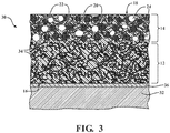
Figure 3 is an enlarged cross-sectional view of a friction plate including the friction material ofFigure 1 and a substrate. -
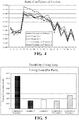
Figure 4 is a graph of static COF over a number of engagement/disengagement cycles for the various Examples and Comparative Examples set forth in the subject disclosure. -
Figure 5 is a bar graph of the durability (lining loss per pack) for the various Examples and Comparative Examples set forth in the subject disclosure. -
Figures 1-5 are exemplary in nature and are not drawn to scale and are thus not intended to represent the relative sizes of the various components of the friction material, e.g. the friction generating layer, the base, the friction generating particles, the fibrillated nanofibers, the elastomeric particles, etc. - Referring to the Figures, wherein like numerals indicate corresponding parts throughout the several views, a friction material is shown generally at 10 and a friction plate is shown generally at 30.
- The
friction material 10 described herein is typically used on afriction plate 30 which is included in a wet clutch assembly in a transmission of a motor vehicle. However, it is to be appreciated that thefriction material 10 andfriction plate 30 described herein can be used in other vehicular applications and have applications beyond motor vehicles. - Referring now to
Figure 1 , thefriction material 10 comprises abase 12 and an indiscreetfriction generating layer 14 penetrating into and integral with thebase 12. The friction generatinglayer 14 is also known in the art as a deposit layer or a deposit. Thebase 12 presents abonding surface 16. The friction generatinglayer 14 presents afriction generating surface 18 facing opposite (and parallel to) thebonding surface 16 of thebase 12. Acurable resin 26 is dispersed throughout thefriction generating layer 14 and thebase 12 of thefriction material 10. - Still referring to
Figure 1 , thefriction material 10 has a thickness T1 defined as a distance between thefriction generating surface 18 and thebonding surface 16. In various embodiments, thefriction generating layer 14 extends from thefriction generating surface 18 towards thebonding surface 16 up to about 40%, alternatively up to about 30%, alternatively up to about 20%, alternatively up to about 10%, alternatively up to about 5%, of the thickness T1. Thebase 12 typically has a thickness T2 of less than about 2 mm, alternatively from about 0.25 mm to about 2 mm, alternatively from about 0.3 mm to about 1 mm, alternatively of from about 0.3 mm to about 0.4 mm. If thefriction material 10 is about 0.25 mm to about 2 mm thick, which is typical for afriction material 10 applied to a clutch plate (wet clutch) in a transmission, thefriction generating layer 14 may extend inwards from thefriction generating surface 18 to a depth up to about 0.0125 mm (5% of 0.25 mm) to about 0.80 mm (40% of 2 mm). - Referring now to
Figure 2 , thefriction generating layer 14 comprisesfibrillated nanofibers 20,friction adjusting particles 22, andelastomeric particles 24. The friction generatinglayer 14 may be referred to as indiscreet because thefibrillated nanofibers 20, thefriction adjusting particles 22, and theelastomeric particles 24, are applied to, and typically penetrate into, thebase 12. Likewise, particles and fibers of thebase 12 may penetrate into thefriction generating layer 14. Accordingly, thefriction generating layer 14 and thebase 12 are integral layers within thefriction material 10. - In various embodiments, the
friction generating layer 14 comprises, consists essentially of, or consists of, thefibrillated nanofibers 20, thefriction adjusting particles 22, and theelastomeric particles 24. In some embodiments, thefriction generating layer 14 comprises, consists essentially of, or consists of, a single type of thefibrillated nanofibers 20, a single type of thefriction adjusting particles 22, and a single type of theelastomeric particles 24. - As used herein, "consists essentially of' is used to describe embodiments that include the specified components (e.g. a
friction material 10 including afriction generating layer 14 including thefibrillated nanofibers 20, thefriction adjusting particles 22, and the elastomeric particles 24) which is free of, or substantially free of (e.g. includes less than 5 wt. % or less than 1 wt. %), other compounds and additives. - Referring now to the
elastomeric particles 24 of thefriction generating layer 14, theelastomeric particles 24 are particles which are elastic and exhibit rubber-like properties. Use of theelastomeric particles 24 in thefriction generating layer 14 provides improved compressibility and an increased coefficient of friction over a wide range of temperatures and conditions. Suitableelastomeric particles 24 are chosen from particles derived from cashew nut shell oil, rubber, and combinations thereof. - In various embodiments, the
elastomeric particles 24 have an elastic modulus of from about 0.01 to about 3, alternatively from about 0.01 to about 2, alternatively from about 0.02 to about 1, alternatively from about 0.03 to about 0.3, GPa. - In various embodiments, the
elastomeric particles 24 have a compressibility of from about 1 to about 10, alternatively from about 1.5 to about 7.5, % when tested in accordance with ISO 6310. - In various embodiments, the
elastomeric particles 24 have a first deflection (amount compressed from original diameter/thickness) of from about 0.5 to about 10, alternatively from about 1 to about 7, % of original thickness when tested in accordance with ISO 6310. - In various embodiments, the
elastomeric particles 24 have a first hysteresis (amount of lost diameter/thickness after load removed) of from about 0.1 to about 10, alternatively from about 0.2 to about 7, % of original thickness when tested in accordance with ISO 6310. - In some embodiments, the
elastomeric particles 24 comprise, consist essentially of, or consist of rubber. Rubber is a polymer that exhibits elasticity. Rubber can be a natural rubber, a modified natural rubber, or a synthetic rubber. The rubber can be defined as an elastomer or a thermoplastic elastomer. In various embodiments theelastomeric particles 24 comprise, consist essentially of, or consist of silicone rubber (including modified silicone rubber), styrene butadiene rubber ("SBR"), butyl rubber, thermoplastic elastomers (including ethylene acrylic elastomers) and halogenated rubbers such as chlorobutyl rubber, bromobutyl rubber, polychloroprene rubber, fluoro rubber (sometimes referred to as fluoroelastomer or perfluoroelastomer), and nitrile rubber (sometimes referred to as buna-N, perbunan, acrylonitrile butadiene rubber, NBR, hydrogenated NBR). - In some embodiments, the
elastomeric particles 24 comprise, consist essentially of, or consist of fluororubber (fluoroelastomer) categorized under the ASTM D1418 & ISO 1629 designation of FKM. This class of elastomers is a family comprising copolymers of hexafluoropropylene (HFP) and vinylidene fluoride (VDF or VF2), terpolymers of tetrafluoroethylene (TFE), vinylidene fluoride (VDF) and hexafluoropropylene (HFP) as well as perfluoromethylvinylether (PMVE) containing specialties. - In some embodiments, the
elastomeric particles 24 comprise, consist essentially of, or consist of, silicone rubber. In other embodiments theelastomeric particles 24 comprise, consist essentially of, or consist of, nitrile rubber. - In a preferred embodiment, the
elastomeric particles 24 comprise, consist essentially of, or consist of, cashew nut particles or particles derived from cashew nut shell oil. Cashew nut particles comprise cashew nut shell liquid, which is a naturally occurring compound found in the honeycomb structure of a cashew nut shell. In some embodiments, theelastomeric particles 24 comprise cashew nut particles which are brown, and in other embodiments, theelastomeric particles 24 comprise cashew nut particles which are black. In such embodiments, the particles may be screened to 100, 90, 80, 70, 60, 50, or 40, mesh. - In various embodiments, the
elastomeric particles 24 have average diameters of less than about 40 µm, alternatively from about 2 µm to about 40 µm, alternatively from about 5 µm to about 30 µm, alternatively from about 5 µm to about 15 µm. Advantageously,elastomeric particles 24 of thefriction generating layer 14 having an average diameter of less than about 40 µm typically improve the compression of thefriction generating layer 14 and, importantly, when used in combination with thefriction adjusting particles 22 and the fibrillatednanofibers 20 unexpectedly yield afriction generating surface 18 having an improved static COF as is explained throughout this disclosure. Without being bound by theory, it is believed that the elasticity and relative lack of rigidity provided by the particles provide a cushioning effect upon compression of thefriction generating surface 18 of thefriction material 10 which evenly distributes pressures at elevated temperature and, thus, improves the static COF of thefriction generating surface 18 without negatively effecting the dynamic COF of thefriction generating surface 18. - In one embodiment, the
friction material 10 comprises thebase 12 and thefriction generating layer 14 comprising the fibrillatednanofibers 20, thefriction adjusting particles 22, and theelastomeric particles 24 having an average diameter of less than about 40 µm. In this embodiment, theelastomeric particles 24 having an average diameter of less than about 40 µm are included in thefriction generating layer 14 in an amount sufficient to increase the static COF of the of thefriction generating surface 18. - Further, in various embodiments, the
elastomeric particles 24 have a thermal stability of about 200°C or greater, alternatively about 250°C or greater, alternatively about 300°C or greater, alternatively about 350°C or greater. By thermal stability it is meant that theelastomeric particles 24 do not melt, soften, or decompose. The thermal stability of theelastomeric particles 24 is typically determined by thermal gravimetric analysis ("TGA"). The temperature at which a test sample of theelastomeric particles 24 analyzed via TGA loses 5 wt. % based on a total weight of the test sample is the temperature at which theelastomeric particles 24 lose thermal stability. - The
elastomeric particles 24 are typically present in thefriction material 10 in an amount of from about 3 to about 15 lbs per 3000 ft2 (about 1.4 to about 6.8 kg per 278.7 m2) of thefriction generating surface 18, alternatively from about 6 to about 12 lbs per 3000 ft2 (about 2.7 kg to about 5.4 kg per 278.7 m2) of thefriction generating surface 18, alternatively from about 8 to about 10 lbs per 3000 ft2 (about 3.6 kg to about 4.5 kg per 278.7 m2) of thefriction generating surface 18, alternatively about 9 lbs per 3000 ft2 (about 4.1 kg per 278.7 m2) of thefriction generating surface 18. The amount of theelastomeric particles 24 present in thefriction generating layer 14 may vary outside of the ranges above, but is typically both whole and fractional values within these ranges. Further, it is to be appreciated that more than one type of theelastomeric particles 24 may be included in thefriction generating layer 14, in which case the total amount of all theelastomeric particles 24 present in thefriction generating layer 14 is within the above ranges. - The amount of the components in the
friction generating layer 14 provided herein are in units of pounds per 3000 ft2, such units are customarily used in the paper making industry as a measurement of weight based on a given surface area of a thin layer, whether impregnated with thecurable resin 26 or not. Above, the units express the weight of theelastomeric particles 24 present in thefriction generating layer 14 for every 3000 ft2 of thefriction generating surface 18. Further below, the units express the weight of the fibrillatednanofibers 20 and thefriction adjusting particles 22 present in thefriction generating layer 14 for every 3000 ft2 of thefriction generating surface 18. - Referring now to the
friction adjusting particles 22 of thefriction generating layer 14, thefriction adjusting particles 22 increase the dynamic COF of thefriction generating surface 18. Various suitablefriction adjusting particles 22 are chosen from silica, carbon, graphite, alumina, magnesia, calcium oxide, titania, ceria, zirconia, cordierite, mullite, sillimanite, spodumene, petalite, zircon, silicon carbide, titanium carbide, boron carbide, hafnium carbide, silicon nitride, titanium nitride, titanium boride, and combinations thereof. Alternatively, various suitablefriction adjusting particles 22 comprise, consist essentially of, or consist of, silica, carbon, graphite, alumina, magnesia, calcium oxide, titania, ceria, zirconia, cordierite, mullite, sillimanite, spodumene, petalite, zircon, silicon carbide, titanium carbide, boron carbide, hafnium carbide, silicon nitride, titanium nitride, titanium boride, or combinations thereof. - In a preferred embodiment, the
friction adjusting particles 22 comprise, consist essentially of, or consist of diatomaceous earth. Diatomaceous earth is a mineral comprising silica. Diatomaceous earth is an inexpensive, abrasive material that exhibits a relatively high COF which readily disperses throughout the fibrillatednanofibers 20 of thefriction generating layer 14. Of course, all of thefriction adjusting particles 22 included in thefriction generating layer 14 may be diatomaceous earth or, alternatively, thefriction adjusting particles 22 may include a combination of different types of thefriction adjusting particles 22, such as various combinations of diatomaceous earth, carbon, graphite, and alumina. The type or types of thefriction adjusting particles 22 included in thefriction generating layer 14 may vary depending on the friction characteristics sought at thefriction generating surface 18 of thefriction material 10. - In various embodiments, the
friction adjusting particles 22 have a Mohs hardness of from about 2 to about 9, alternatively from about 3 to about 9, alternatively from about 5 to about 6.5, alternatively from about 5.5 to about 6. The hardness of thefriction adjusting particles 22 stands in contrast to the elasticity/elastic modulus of theelastomeric particles 24 and it is believed that the disclosed combination offriction adjusting particles 22 andelastomeric particles 24 provides thefriction generating layer 14 with excellent static and dynamic friction characteristics. - In various embodiments, the
friction adjusting particles 22 have an average diameter of from about 1 µm to about 30 µm, alternatively from about 5 µm to about 16 µm. Further, in various embodiments, thefriction adjusting particles 22 have a thermal stability of about 400°C or greater, alternatively 450°C or greater, alternatively 500°C or greater. By thermal stability it is meant that thefriction adjusting particles 22 do not melt, soften, or decompose. The thermal stability of thefriction adjusting particles 22 is typically determined by TGA. The temperature at which a test sample of thefriction adjusting particles 22 analyzed via TGA loses 5 wt. % based on a total weight of the test sample is the temperature at which thefriction adjusting particles 22 lose thermal stability. - The
friction adjusting particles 22 are typically present in thefriction material 10 in an amount of from about 7 to about 23 lbs per 3000 ft2 (about 3.2 to about 10.4 kg per 278.7 m2) of thefriction generating surface 18, alternatively from about 10 to about 20 lbs per 3000 ft2 (about 4.5 to about 9.1 kg per 278.7 m2) of thefriction generating surface 18, alternatively from about 12 to about 18 lbs per 3000 ft2 (about 5.4 to about 8.2 kg per 278.7 m2) of thefriction generating surface 18, alternatively about 15 lbs per 3000 ft2 (about 6.8 kg per 278.7 m2) of thefriction generating surface 18. The amount of thefriction adjusting particles 22 present in thefriction generating layer 14 may vary outside of the ranges above, but is typically both whole and fractional values within these ranges. Further, it is to be appreciated that more than one type of thefriction adjusting particles 22 may be included in thefriction generating layer 14, in which case the total amount of all thefriction adjusting particles 22 present in thefriction generating layer 14 is within the above ranges. - In a preferred embodiment, the
friction adjusting particles 22 and theelastomeric particles 24 are present in thefriction generating layer 14 in a weight ratio of from about 3:1 to about 1:1. - Referring now to the fibrillated
nanofibers 20 of thefriction generating layer 14, the fibrillatednanofibers 20 are chosen from cellulose fibers, aramid fibers, acrylic fibers, and combinations thereof. Alternatively, the fibrillatednanofibers 20 of thefriction generating layer 14 comprise, consist essentially of, or consist of, cellulose fibers, aramid fibers, acrylic fibers, or combinations thereof. - In a typical embodiment, the fibrillated
nanofibers 20 comprise cellulose. For example, in various embodiments the fibrillatednanofibers 20 comprise natural cellulose, regenerated cellulose, a cellulose derivative, or a mixture thereof. In some embodiments, the fibrillatednanofibers 20 comprise at least 50 wt. %, alternatively at least 60 wt. %, alternatively at least 70 wt. %, alternatively at least 80 wt. %, alternatively at least 90 wt. %, alternatively at least 99 wt. %, alternatively about 100 wt. %, of natural cellulose, regenerated cellulose, a cellulose derivative, or a mixture thereof. In various embodiments, the fibrillatednanofibers 20 consist essentially of, or consist of, cellulose. In some embodiments, the fibrillatednanofibers 20 comprise, consist essentially of, or consist of natural cellulose. In other embodiments, the fibrillatednanofibers 20 comprise, consist essentially of, or consist of, regenerated cellulose. For example, in such other embodiments, the fibrillatednanofibers 20 comprise, consist essentially of, or consist of, regenerated lyocell cellulose. - Natural cellulose is a straight chain polysaccharide that includes repeating β(1→4)-glycosidic-linked glucose units and which has the general polymeric formula (C6H1O5)n with the number of repeating units ("n") usually ranging from 100 to 10,000. Regenerated cellulose has the same chemical formula as natural cellulose and is prepared from naturally-occurring polymers (e.g. wood pulp or bamboo) from one of several processes including the viscose process, the cuprammonium process, and an organic solvent spinning process. Some examples of regenerated cellulose are rayon, modal, and lyocell. A cellulose derivative is a modified cellulose in which the hydroxyl group on the glucose units is fully or partially substituted with, for example, an ester group. Some examples of a cellulose derivative are cellulose acetate and cellulose triacetate.
- In some embodiments, the fibrillated
nanofibers 20 comprise aramid. For example, in various embodiments the aramid is synthetic aromatic polyamide. One such example of aromatic polyamide is para-aramid, such as the condensation product of 1,4-phenylene-diamine and terephthaloyl chloride. Another such example of aromatic polyamide is meta-aramid, such as the condensation product of m-phenylenediamine and isophthaloyl chloride. - In some embodiments, the fibrillated
nanofibers 20 comprise acrylic. For example, in various embodiments, the acrylic is a synthetic acrylic polymer formed from at least 85 wt. % acrylonitrile monomers. - In various embodiments, the fibrillated
nanofibers 20 have average diameters of from about 20 nm to about 800 nm, alternatively from about 30 nm to about 600 nm, alternatively from about 50 nm to about 500 nm, and average lengths of from about 1 mm to about 10 mm, alternatively from about 2 mm to about 8 mm, alternatively from about 4 mm to about 6 mm. In such embodiments, the fibrillatednanofibers 20 typically have a degree of fibrillation as measured according to Canadian Standard Freeness ("CSF") of from about 5 ml CSF to about 300 ml CSF, alternatively from about 10 ml CSF to about 200 ml CSF, alternatively from about 10 ml CSF to about 100 ml CSF. CSF is an empirical test procedure that measures the rate at which 3 grams of a fibrous pulp material in 1 liter of water may be drained. CSF measurements are conducted in accordance with the TAPPI T227 test procedure. In making CSF measurements, it is noted that a more fibrillated fibrous pulp material will have a lower water drainage rate and, thus, a lower "ml CSF" value, and that a less fibrillated fibrous pulp material will have a higher "ml CSF" value. - Further, in various embodiments, the fibrillated
nanofibers 20 have a thermal stability of about 200°C or greater, alternatively 250°C or greater, alternatively 350°C or greater. By thermal stability it is meant that the fibrillatednanofibers 20 do not melt, soften, or decompose. The thermal stability of the fibrillatednanofibers 20 is typically determined by TGA. The temperature at which a test sample of theelastomeric particles 24 analyzed via TGA loses 5 wt. % based on a total weight of the test sample is the temperature at which theelastomeric particles 24 lose thermal stability. - The fibrillated
nanofibers 20 are typically present in thefriction material 10 in an amount of from about 1 to about 6 lbs per 3000 ft2 (about 0.5 kg to about 2.7 kg per 278.7 m2) of thefriction generating surface 18, alternatively from about 2 to about 5 lbs per 3000 ft2 (about 0.9 kg to about 2.3 kg per 278.7 m2) of thefriction generating surface 18, alternatively from about 2 to about 4 lbs per 3000 ft2 (about 0.9 kg to about 1.8 kg per 278.7 m2) of thefriction generating surface 18, alternatively about 3 lbs per 3000 ft2 (about 1.4 kg per 278.7 m2) of thefriction generating surface 18. The amount of the fibrillatednanofibers 20 present in thefriction generating layer 14 may vary outside of the ranges above, but is typically both whole and fractional values within these ranges. Further, it is to be appreciated that more than one type of the fibrillatednanofibers 20 may be included in thefriction generating layer 14, in which case the total amount of all the fibrillatednanofibers 20 present in thefriction generating layer 14 is within the above ranges. - In a preferred embodiment, about 6 lbs to about 12 lbs of the
elastomeric particles 24, about 10 lbs to about 20 lbs of thefriction adjusting particles 22, and about 1 to about 7 lbs of the fibrillatednanofibers 20, each based on about 3000 ft2 of thefriction generating surface 18 are present in thefriction generating layer 14. - The amounts of the fibrillated
nanofibers 20 and thefriction adjusting particles 22 can be chosen to affect the frictional characteristics of thefriction material 10. The porosity of thefriction material 10 at thefriction generating surface 18, for instance, is inversely proportional to the amount of the fibrillatednanofibers 20 present in thefriction generating layer 14. The amount of thefriction adjusting particles 22 present in thefriction generating layer 14 influences both the static and dynamic COF that can be achieved at thefriction generating surface 18. Although a higher COF generally accompanies a higher amount offriction adjusting particles 22 and vice versa, use of thefriction adjusting particles 22 and the fibrillatednanofibers 20 alone does not allow for significant improvement of the static COF of thefriction material 10. Advantageously, the use of theelastomeric particles 24 along with thefriction adjusting particles 22 and the fibrillatednanofibers 20 in thefriction generating layer 14 in the amounts disclosed herein significantly improves the dynamic and static COF of thefriction material 10. - In another preferred embodiment, the
friction material 10 includes afriction generating layer 14 comprising: (1) fibrillatednanofibers 20 comprising cellulose and having an average length of from about 1 mm to about 10 mm and an average degree of fibrillation of from about 10 mL CSF to about 300 mL CSF as measured by Canadian Standard Freeness, wherein the fibrillatednanofibers 20 are present in thefriction generating layer 14 in an amount of from about 1 to about 6 lbs per 3000 ft2 (about 0.5 kg to about 2.7 kg per 278.7 m2) of thefriction generating surface 18; (2) thefriction adjusting particles 22 comprising diatomaceous earth and present in thefriction generating layer 14 an amount of from about 7 to about 23 lbs per 3000 ft2 (about 3.2 to about 10.4 kg per 278.7 m2); and (3)elastomeric particles 24 derived from cashew nut shell oil and having an average diameter of less than about 40 µm, theelastomeric particles 24 present in an amount of from about 3 to about 15 lbs per 3000 ft2 (about 1.4 to about 6.8 kg per 278.7 m2) of thefriction generating surface 18. In this embodiment, thecurable resin 26 is dispersed throughout thefriction generating layer 14 and the base 12 in an amount of less than about 40 wt. % based on 100 parts by weight of thefriction material 10. The combination of the fibrillatednanofibers 20, thefriction adjusting particles 22, andelastomeric particles 24 in thefriction generating layer 14 not only provides thefriction material 10 with an excellent dynamic and static COF, the combination advantageously allows for a reduction in the amount ofcurable resin 26 required, and, as is set forth below, the combination also allows for a reduction in the thickness of thebase 12. - Referring now to the
base 12 of thefriction material 10, thebase 12 typically comprises variousstructural fibers 28 and fillers. In a preferred embodiment, thebase 12 comprises thestructural fibers 28 which penetrate into thefriction generating layer 14 and intermingle with the fibrillatednanofibers 20. To this end, thebase 12 can be referred to as indiscreet, just like thefriction generating layer 14. In some embodiments, thestructural fibers 28 of the base 12 are exposed at thefriction generating surface 18. In other embodiments, thestructural fibers 28 of the base 12 are not exposed at thefriction generating surface 18. Thestructural fibers 28 are typically chosen from cellulose fibers, aramid fibers, acrylic fibers, glass fibers, ceramic fibers, novoloid (phenol-formaldehyde) fibers, carbon fibers, mineral fibers, and combinations thereof. The various types of cellulose, aramid, and acrylic fibers are just as described above in reference to the fibrillatednanofibers 20 of thefriction generating layer 14. Carbon fibers, sometimes referred to as graphite fibers, are fibers comprising carbon atoms. Of course, carbon fibers as discussed herein include fibers formed with carbon and other materials, i.e. composite carbon fibers. - In various embodiments, the
structural fibers 28 have average diameters of from about 20 nm to about 2000 nm, alternatively from about 30 nm to about 1750 nm, alternatively from about 50 nm to about 1500 nm, and average lengths of from about 2 mm to about 20 mm, alternatively from about 4 mm to about 18 mm, alternatively from about 6 mm to about 16 mm. In such embodiments, thestructural fibers 28 typically have a degree of fibrillation as measured according to CSF of from about 100 ml CSF to about 1000 ml CSF, alternatively from about 100 ml CSF to about 800 ml CSF, alternatively from about 100 ml CSF to about 650 ml CSF. - In one embodiment, the
base 12 includes fibrillated microstructural fibers 28 comprising aramid such as poly-paraphenylene terephthalamide. In another embodiment, thebase 12 includesstructural fibers 28 comprising cellulose. In another embodiment, thebase 12 includesstructural fibers 28 comprising carbon. In a preferred embodiment, thebase 12 includes individualstructural fibers 28 comprising, consisting of, or consisting essentially of aramid and cellulose. The combination of these two types of microfibers provides the base 12 with thermal and chemical stability and a high fatigue resistance well above 350°C. The aramid and cellulosestructural fibers 28 present in thebase 12 of this embodiment may be natural or synthetic. - The
structural fibers 28 are typically present in thefriction material 10 in an amount of from about 10 to about 90 wt. %, alternatively from about 20 to about 70 wt. %, based on the total weight of thebase 12. The amount of thestructural fibers 28 present in thebase 12 may vary outside of the ranges above, but is typically both whole and fractional values within these ranges. Further, it is to be appreciated that more than one type of thestructural fibers 28 may be included in thebase 12, in which case the total amount of all thestructural fibers 28 present in thebase 12 is within the above ranges. - Referring now to the fillers of the
base 12, the fillers include chosen from silica, carbon, graphite, alumina, magnesia, calcium oxide, titania, ceria, zirconia, cordierite, mullite, sillimanite, spodumene, petalite, zircon, silicon carbide, titanium carbide, boron carbide, hafnium carbide, silicon nitride, titanium nitride, titanium boride, diatomaceous earth, cashew nut particles, and combinations thereof. Alternatively, the fillers of the base 12 comprise, consisting essentially of, or consist of, silica, carbon, graphite, alumina, magnesia, calcium oxide, titania, ceria, zirconia, cordierite, mullite, sillimanite, spodumene, petalite, zircon, silicon carbide, titanium carbide, boron carbide, hafnium carbide, silicon nitride, titanium nitride, titanium boride, diatomaceous earth, cashew nut particles, and combinations thereof. In a preferred embodiment, the filler of thebase 12 includes a combination of diatomaceous earth and carbon. - In various preferred embodiments, the
base 12 is substantially free of theelastomeric particles 24. In these embodiments, theelastomeric particles 24, such as those derived from cashew nut particles, are present in the base 12 in an amount of from less than about 1, alternatively less than about 0.5, alternatively less than about 0.25, alternatively less than about 0.1, alternatively 0, wt. % based on the total weight of thebase 12. Of course, in these embodiments, some of theelastomeric particles 24 added to thefriction generating layer 14 may intermingle with or penetrate into thebase 12, but prior to application of the components of thefriction generating layer 14, thebase 12 is substantially free of theelastomeric particles 24. - The filler is typically present in the
friction material 10 in an amount of from about 20 to about 80 wt. %, alternatively about 20 to about 60 wt. %, based on the total weight of thebase 12. The amount of the filler present in thebase 12 may vary outside of the ranges above, but is typically both whole and fractional values within these ranges. Further, it is to be appreciated that more than one type of the filler may be included in thebase 12, in which case the total amount of all the fillers present in thebase 12 is within the above ranges. - Referring now to the
curable resin 26 that is dispersed throughout thefriction generating layer 14 and thebase 12 of thefriction material 10. Thecurable resin 26 may be any thermosetting resin suitable for providing structural strength to thefriction material 10. Thecurable resin 26 may, for example, be a phenolic resin or a modified phenolic resin (e.g. an epoxy phenolic, etc.) A phenolic resin is a class of thermosetting resins that is produced by the condensation of an aromatic alcohol, typically a phenol, and an aldehyde, typically a formaldehyde. A phenolic-based resin is a thermosetting resin blend that includes at least 50 wt. % of a phenolic resin based on the total weight of all resins and excluding any solvents or processing acids. Some examples of other thermosetting resins that may be blended with a phenolic resin include silicone resins, epoxy resins, and polybutadiene resins, to name but a few examples. Once cured, thecurable resin 26 is referred to as the curedresin 34, the curedresin 34 confers strength and durability to thefriction material 10 and adheres theelastomeric particles 24, the fibrillatednanofibers 20, and thefriction adjusting particles 22 in thefriction generating layer 14 while maintaining a desired porosity for proper lubricant flow and retention. - The
curable resin 26 is present in thefriction material 10 in an amount of less than about 50 wt. %, alternatively less than about 45, alternatively less than about 40, alternatively from about 20 wt. % to about 35 wt. %, alternatively from about 25 wt. % to about 30 wt. %, based on 100 parts by weight of thefriction material 10. Advantageously, the combination of theelastomeric particles 24, the fibrillatednanofibers 20, and thefriction adjusting particles 22 in thefriction generating layer 14 allows for reduction in an amount of thecurable resin 26 in thefriction material 10 providing excellent performance properties (e.g. COF and wear properties). - Referring now to
Figure 3 , thefriction plate 30 comprises thefriction material 10, which is cured (i.e. comprising cured resin 34) bonded to asubstrate 32 with abonding adhesive 36. Thebonding surface 16 is the surface of thefriction material 10 where bonding to thesubstrate 32 or other material is meant to be accomplished. As such, thebonding surface 16 of thebase 12 is bonded to asubstrate 32. - The
friction material 10 is bonded to thesubstrate 32 by any suitable technique known to skilled artisans. Typically, thefriction material 10 is bonded to thesubstrate 32 with thebonding adhesive 36, which is generally known to those skilled in the art, e.g. with abonding adhesive 36 comprising phenolic modified nitrile rubber.Exemplary substrates 32 include, but are not limited to, friction/clutch plates, synchronizer rings, and transmission bands. Thesubstrate 32 is typically metal. - As alluded to above, the various embodiments of the
friction material 10 described herein may be used in a wet clutch. Thefriction generating surface 18 of thefriction material 10 experiences interfacial frictional engagement with an opposed mating surface (not shown) in the presence of a lubricant. Thefriction generating surface 18 experiences select interfacial frictional engagement with an opposed, rotating surface (not shown) in the presence of a lubricant, and thebonding surface 16 achieves bonded attachment to thesubstrate 32 with the aid of an adhesive or some other suitable bonding technique. The lubricant may be any suitable lubricating fluid such as, for example, an automatic transmission fluid. While thefriction material 10 performs satisfactorily above about 350°C, alternatively about 400°C, alternatively about 450°C, it is not limited only to such high-temperature environments and may, if desired, be used in a wet clutch designed to maintain a temperature at thefriction generating surface 18 below 350°C. - The
friction material 10 can maintain a positive µ-v relationship and resist glazing because itsfriction generating surface 18 is able to be repeatedly regenerated. Such regeneration can be attributed to the presence of the fibrillated cellulose nanofibers and their supportedfriction adjusting particles 22. The balanced content of those two materials (the fibrillatednanofibers 20 and the friction adjusting particles 22) provides enoughfriction adjusting particles 22 at or near thefriction generating surface 18 to sustain a positive µ-v relationship at elevated temperatures while permitting the fibrillated cellulose nanofibers closest to thefriction generating surface 18 to thermally decompose at regular intervals. - In addition, the combination of the fibrillated
nanofibers 20, thefriction adjusting particles 22, andelastomeric particles 24 in thefriction generating layer 14 provides afriction material 10 with excellent dynamic and static COF, the combination advantageously allows for a reduction in the amount ofcurable resin 26 required, and also allows for a reduction in the thickness of thebase 12, as is set forth in the Examples below. Without being bound by theory, it is believed that theelastomeric particles 24 offriction generating layer 14 and a reduced amount ofcurable resin 26 increase the compressibility of thefriction generating layer 14. In turn, many such embodiments of thefriction material 10 exhibit excellent dynamic and static COF as well as durability characteristics in wet clutch applications. - The following examples are meant to illustrate the disclosure and are not to be viewed in any way as limiting to the scope of the disclosure.
- Example friction materials representative of this disclosure (Examples 1 and 2) are formed along with three comparative examples of friction materials that are not representative of this disclosure (Comparative Examples 1-3.) After formation, the Examples and the Comparative Examples are evaluated to determine a variety of performance properties. The compositions of Examples 1 and 2 and Comparative Examples 1-3 are set forth in Table 1 below.
TABLE 1 Friction Material Component Example 1 Example 2 Comparative Example 1 Comparative Example 2 Comparative Example 3 Base A Structural Fibers A and B 40-60 wt. % 40-60 wt. % 40-60 wt. % 40-60 wt. % 40-60 wt. % Fillers A and B 35-55 wt. % 35-55 wt. % 35-55 wt. % 35-55 wt. % 35-55 wt. % Friction Generating Layer Friction Adjusting Particle 10-20 lbs / 3000 ft2 10-20 lbs / 3000 ft2 --- 10-20 lbs / 3000 ft2 10-20 lbs / 3000 ft2 Fibrillated Nanofiber 2-5 lbs / 3000 ft2 2-5 lbs / 3000 ft2 --- 2-5 lbs / 3000 ft2 2-5 lbs / 3000 ft2 Elastomeric Particle 6-12 lbs / 3000 ft2 6-12 lbs / 3000 ft2 --- --- --- Curable Resin Phenolic Resin 35-45 23-33 35-45 35-45 23-33 - Structural Fibers A and B comprise aramid and natural cellulose, respectively.
- Fillers A and B comprise diatomaceous earth and graphite, respectively.
- Friction Adjusting Particle is diatomaceous earth having a Mohs hardness of from about 5.5 to about 6.
- Fibrillated Nanofiber is a lyocell cellulose fiber.
- Elastomeric Particle is a particle comprising a cashew nut shell oil derivative having a mean diameter of about 12 µm and a compressibility of from about 1.5 to 7.5%.
- Examples 1 and 2 and Comparative Examples 1-3 are cured and bonded to a metal substrate to form friction plates.
- The friction plates including the friction materials of Example 1 and Comparative Examples 1 and 2 are then tested in duplicate on a No. 2 Friction Test Machine in accordance with SAE procedure J2490 (µPVT). The SAE No. 2 Friction Test Machine is used to evaluate the friction characteristics of automatic transmission plate clutches with automotive transmission fluids as well as durability tests on wet friction systems. Testing was conducted in Dual Clutch Transmission ("DCT") fluid.
- Measurements for Initial COF, Midpoint COF, Static COF, E/M ratio were plotted against the number of friction material engagement/disengagement cycles. The Static COF of the Examples and Comparative Examples is set forth in
Figure 4 . InFigure 4 , Examples 1 and 2 demonstrate improved static COF over the Comparative Examples. Durability testing (lining loss mm/pack) was conducted as well. The durability of the Examples and Comparative Examples is set forth inFigure 5 . InFigure 5 , Examples 1 and 2 demonstrate improved durability over the Comparative Examples. Further, Example 2, which includes less wt. % resin, demonstrates improved friction characteristics over Example 1, which includes more wt. % resin. That is, the friction generating layer of the subject disclosure requires less resin and demonstrates improved friction and durability characteristics with less resin. - It is to be understood that the appended claims are not limited to express any particular compounds, compositions, or methods described in the detailed description, which may vary between particular embodiments which fall within the scope of the appended claims. With respect to any Markush groups relied upon herein for describing particular features or aspects of various embodiments, it is to be appreciated that different, special, and/or unexpected results may be obtained from each member of the respective Markush group independent from all other Markush members. Each member of a Markush group may be relied upon individually and or in combination and provides adequate support for specific embodiments within the scope of the appended claims.
- It is also to be understood that any ranges and subranges relied upon in describing various embodiments of the present disclosure independently and collectively fall within the scope of the appended claims, and are understood to describe and contemplate all ranges including whole and/or fractional values therein, even if such values are not expressly written herein. One of skill in the art readily recognizes that the enumerated ranges and subranges sufficiently describe and enable various embodiments of the present disclosure, and such ranges and subranges may be further delineated into relevant halves, thirds, quarters, fifths, and so on. As just one example, a range "of from 0.1 to 0.9" may be further delineated into a lower third, i.e. from 0.1 to 0.3, a middle third, i.e. from 0.4 to 0.6, and an upper third, i.e. from 0.7 to 0.9, which individually and collectively are within the scope of the appended claims, and may be relied upon individually and/or collectively and provide adequate support for specific embodiments within the scope of the appended claims. In addition, with respect to the language which defines or modifies a range, such as "at least," "greater than," "less than," "no more than," and the like, it is to be understood that such language includes subranges and/or an upper or lower limit. As another example, a range of "at least 10" inherently includes a subrange of from at least 10 to 35, a subrange of from at least 10 to 25, a subrange of from 25 to 35, and so on, and each subrange may be relied upon individually and/or collectively and provides adequate support for specific embodiments within the scope of the appended claims. Finally, an individual number within a disclosed range may be relied upon and provides adequate support for specific embodiments within the scope of the appended claims. For example, a range "of from 1 to 9" includes various individual integers, such as 3, as well as individual numbers including a decimal point (or fraction), such as 4.1, which may be relied upon and provide adequate support for specific embodiments within the scope of the appended claims.
Claims (15)
- A friction material comprising:(A) a base presenting a bonding surface;(B) a friction generating layer penetrating into said base and presenting a friction generating surface facing opposite said bonding surface of said base, said friction generating layer comprising:(i) fibrillated nanofibers;(ii) friction adjusting particles; and(iii) elastomeric particles;
wherein the (i) fibrillated nanofibers; (ii) friction adjusting particles; and (iii) elastomeric particles are different; and(C) a curable resin dispersed throughout said friction generating layer and said base. - A friction material as set forth in claim 1 wherein said elastomeric particles are chosen from cashew nut particles, rubber, and combinations thereof.
- A friction material as set forth in any preceding claim wherein said elastomeric particles are chosen from silicone rubber, styrene butadiene rubber, butyl rubber, ethylene acrylic rubber, chlorobutyl rubber, bromobutyl rubber, polychloroprene rubber, nitrile rubber, fluoroelastomer, and combinations thereof.
- A friction material as set forth in any preceding claim wherein said elastomeric particles have an average diameter of less than about 40 µm and/or a thermal stability of about 200°C or greater, wherein thermal stability is determined by thermal gravimetric analysis and is defined as temperatures below a temperature at which a test sample of said elastomeric particles loses 5 wt. % based on an initial weight of the test sample of said elastomeric particles.
- A friction material as set forth in any preceding claim wherein said elastomeric particles are present in an amount of from about 3 to about 15 lbs per 3000 ft2 (about 1.4 to about 6.8 kg per 278.7 m2) of said friction generating surface.
- A friction material as set forth in any preceding claim wherein said friction adjusting particles are chosen from silica, carbon, graphite, alumina, magnesia, calcium oxide, titania, ceria, zirconia, cordierite, mullite, sillimanite, spodumene, petalite, zircon, silicon carbide, titanium carbide, boron carbide, hafnium carbide, silicon nitride, titanium nitride, titanium boride, and combinations thereof, and are present in an amount of from about 7 to about 23 lbs per 3000 ft2 (about 3.2 to about 10.4 kg per 278.7 m2) of said friction generating surface.
- A friction material as set forth in any preceding claim wherein said elastomeric particles have a Mohs hardness of from about 5 to about 6.5.
- A friction material as set forth in any preceding claim wherein said friction adjusting particles and said elastomeric particles are present in a weight ratio of from about 3:1 to about 1:1.
- A friction material as set forth in any preceding claim wherein said fibrillated nanofibers are chosen from acrylic fibers, aramid fibers, carbon fibers, cellulose fibers, and combinations thereof, and are present in an amount of from about 1 to about 6 lbs per 3000 ft2 (about 0.5 kg to about 2.7 kg per 278.7 m2) of said friction generating surface.
- A friction material as set forth in any preceding claim having a thickness defined as a distance between said friction generating surface and said bonding surface wherein said friction generating layer extends from said friction generating surface towards said bonding surface up to about 40% of said thickness.
- A friction material as set forth in any preceding claim wherein said friction generating layer includes less than 5 wt. % of compounds other than said fibrillated nanofibers, said friction adjusting particles, said elastomeric particles, based on a total weight of all components included in said friction generating layer.
- A friction material as set forth in any preceding claim wherein said base is substantially free of elastomeric particles.
- A friction material as set forth in any preceding claim wherein said curable resin is a phenolic resin and/or a modified phenolic resin and wherein said curable resin is present in an amount of less than about 50 wt. % based on 100 parts by weight of said friction material.
- A friction plate comprising a friction material as set forth in any preceding claim which is cured, wherein said bonding surface of said base of said cured friction material is bonded to a substrate.
- A friction material as set forth in any preceding claim wherein said friction adjusting particles comprise diatomaceous earth.
Applications Claiming Priority (2)
| Application Number | Priority Date | Filing Date | Title |
|---|---|---|---|
| US201562264644P | 2015-12-08 | 2015-12-08 | |
| PCT/US2016/063465 WO2017100001A1 (en) | 2015-12-08 | 2016-11-23 | Friction material |
Publications (3)
| Publication Number | Publication Date |
|---|---|
| EP3387285A1 EP3387285A1 (en) | 2018-10-17 |
| EP3387285A4 EP3387285A4 (en) | 2019-07-31 |
| EP3387285B1 true EP3387285B1 (en) | 2021-01-13 |
Family
ID=59013105
Family Applications (1)
| Application Number | Title | Priority Date | Filing Date |
|---|---|---|---|
| EP16873589.2A Active EP3387285B1 (en) | 2015-12-08 | 2016-11-23 | Friction material |
Country Status (6)
| Country | Link |
|---|---|
| US (1) | US11199233B2 (en) |
| EP (1) | EP3387285B1 (en) |
| JP (1) | JP6900373B2 (en) |
| KR (1) | KR20180082589A (en) |
| CN (1) | CN108350967B (en) |
| WO (1) | WO2017100001A1 (en) |
Families Citing this family (6)
| Publication number | Priority date | Publication date | Assignee | Title |
|---|---|---|---|---|
| EP3473883B1 (en) | 2017-10-23 | 2021-11-17 | BorgWarner Inc. | Friction material |
| EP3594525A1 (en) * | 2018-07-12 | 2020-01-15 | MAT Commercial Vehicle Products GmbH | Brake pad, disk brake assembly, and vehicle |
| CN109163040B (en) * | 2018-11-01 | 2020-02-18 | 石家庄硕茂摩擦材料科技有限公司 | A kind of wear-resistant universal brake pad friction block formula with stable friction coefficient and preparation method thereof |
| CN113153926A (en) * | 2020-01-07 | 2021-07-23 | 博格华纳公司 | Clutch system and vehicle transmission system comprising a clutch system |
| US12366275B2 (en) | 2020-04-29 | 2025-07-22 | Schaeffler Technologies AG & Co. KG | Method for forming a double layer wet friction material with cellulose layer |
| DE102020113510A1 (en) | 2020-05-19 | 2021-11-25 | Tmd Friction Services Gmbh | Damping material for a damping or intermediate layer for brake linings and a method for producing the damping material |
Family Cites Families (20)
| Publication number | Priority date | Publication date | Assignee | Title |
|---|---|---|---|---|
| US4111891A (en) | 1976-11-12 | 1978-09-05 | Johns-Manville Corporation | Friction material for railroad disc brakes |
| US4119591A (en) | 1977-07-05 | 1978-10-10 | The Bendix Corporation | Friction material reinforced with steel and cellulose fibers |
| US4218361A (en) | 1979-03-14 | 1980-08-19 | Molded Materials Company, Div. Carlisle Corporation | Friction material |
| KR950702909A (en) | 1992-08-17 | 1995-08-23 | 패트릭 디. 쿠갠 | Particle binder |
| US5707905A (en) | 1993-08-04 | 1998-01-13 | Borg-Warner Automotive, Inc. | Fibrous base material for a friction lining material comprising less fibrillated aramid fibers and synthetic graphite |
| US6001750A (en) | 1993-08-04 | 1999-12-14 | Borg-Warner Automotive, Inc. | Fibrous lining material comprising a primary layer having less fibrillated aramid fibers, carbon fibers, carbon particles and a secondary layer comprising carbon particles |
| US6130176A (en) | 1993-08-04 | 2000-10-10 | Borg-Warner Inc. | Fibrous base material for a friction lining material comprising less fibrillated aramid fibers and carbon fibers |
| US5753356A (en) | 1993-08-04 | 1998-05-19 | Borg-Warner Automotive, Inc. | Friction lining material comprising less fibrillated aramid fibers and synthetic graphite |
| US5856244A (en) | 1993-08-04 | 1999-01-05 | Borg-Warner Automotive, Inc. | Carbon deposit friction lining material |
| US5998307A (en) | 1993-08-04 | 1999-12-07 | Borg-Warner Autotive, Inc. | Fibrous lining material comprising a primary layer having less fibrillated aramid fibers and synthetic graphite and a secondary layer comprising carbon particles |
| JP3831430B2 (en) | 1995-05-23 | 2006-10-11 | Nskワーナー株式会社 | Method for producing wet friction material |
| DE60135235D1 (en) * | 2000-06-12 | 2008-09-18 | Mitsui Chemicals Inc | PHENOLIC COMPOSITION |
| US6630416B1 (en) | 2000-11-06 | 2003-10-07 | Borgwarner Inc. | Friction material formed by deposition of friction modifiers on high, wet energy carbonaceous friction materials |
| US20060009541A1 (en) * | 2004-07-09 | 2006-01-12 | Yih-Fang Chen | Saturant for friction material containing friction modifying layer |
| US8603614B2 (en) | 2004-07-26 | 2013-12-10 | Borgwarner Inc. | Porous friction material with nanoparticles of friction modifying material |
| JP5052803B2 (en) | 2006-03-24 | 2012-10-17 | 日本碍子株式会社 | Composite brake and method of manufacturing the same |
| JP5037478B2 (en) * | 2008-11-18 | 2012-09-26 | 三菱電機株式会社 | Brake braking part |
| KR101498611B1 (en) * | 2009-01-09 | 2015-03-04 | 보르그워너 인코퍼레이티드 | Friction material including a plurality of binder particles with friction modifying particles bound thereto |
| US9777785B2 (en) * | 2011-08-08 | 2017-10-03 | Borgwarner Inc. | Wet friction material |
| JP6006096B2 (en) * | 2012-11-22 | 2016-10-12 | 東レ・ダウコーニング株式会社 | Lubricant coating composition |
-
2016
- 2016-11-23 KR KR1020187017621A patent/KR20180082589A/en not_active Ceased
- 2016-11-23 US US16/060,329 patent/US11199233B2/en active Active
- 2016-11-23 EP EP16873589.2A patent/EP3387285B1/en active Active
- 2016-11-23 CN CN201680067763.5A patent/CN108350967B/en active Active
- 2016-11-23 WO PCT/US2016/063465 patent/WO2017100001A1/en not_active Ceased
- 2016-11-23 JP JP2018524380A patent/JP6900373B2/en active Active
Non-Patent Citations (1)
| Title |
|---|
| None * |
Also Published As
| Publication number | Publication date |
|---|---|
| EP3387285A4 (en) | 2019-07-31 |
| JP6900373B2 (en) | 2021-07-07 |
| US11199233B2 (en) | 2021-12-14 |
| JP2019504131A (en) | 2019-02-14 |
| US20190003544A1 (en) | 2019-01-03 |
| WO2017100001A1 (en) | 2017-06-15 |
| EP3387285A1 (en) | 2018-10-17 |
| CN108350967A (en) | 2018-07-31 |
| KR20180082589A (en) | 2018-07-18 |
| CN108350967B (en) | 2019-10-25 |
Similar Documents
| Publication | Publication Date | Title |
|---|---|---|
| EP3348855B1 (en) | Friction material | |
| EP3387285B1 (en) | Friction material | |
| KR100571527B1 (en) | A two-ply fibrous base material, a non-asbestos friction material comprising said material and a process for producing said non-asbestos fricthion material | |
| EP2742253B1 (en) | Wet friction material | |
| CN103003591B (en) | Friction member and friction material thereof | |
| EP3397717B1 (en) | Friction material | |
| US10995810B2 (en) | Friction material | |
| CN109695648B (en) | Friction material | |
| US20210207673A1 (en) | Friction material | |
| CN103038535B (en) | Friction member and friction material thereof | |
| EP1679337B1 (en) | Carbon fiber composite material and wet friction member | |
| US10989263B2 (en) | Friction material | |
| US8461064B2 (en) | Friction member and friction material thereof | |
| US20210207674A1 (en) | Friction material | |
| US20220325767A1 (en) | Friction material |
Legal Events
| Date | Code | Title | Description |
|---|---|---|---|
| STAA | Information on the status of an ep patent application or granted ep patent |
Free format text: STATUS: THE INTERNATIONAL PUBLICATION HAS BEEN MADE |
|
| PUAI | Public reference made under article 153(3) epc to a published international application that has entered the european phase |
Free format text: ORIGINAL CODE: 0009012 |
|
| STAA | Information on the status of an ep patent application or granted ep patent |
Free format text: STATUS: REQUEST FOR EXAMINATION WAS MADE |
|
| 17P | Request for examination filed |
Effective date: 20180703 |
|
| AK | Designated contracting states |
Kind code of ref document: A1 Designated state(s): AL AT BE BG CH CY CZ DE DK EE ES FI FR GB GR HR HU IE IS IT LI LT LU LV MC MK MT NL NO PL PT RO RS SE SI SK SM TR |
|
| AX | Request for extension of the european patent |
Extension state: BA ME |
|
| DAV | Request for validation of the european patent (deleted) | ||
| DAX | Request for extension of the european patent (deleted) | ||
| A4 | Supplementary search report drawn up and despatched |
Effective date: 20190702 |
|
| RIC1 | Information provided on ipc code assigned before grant |
Ipc: F16D 69/04 20060101ALI20190626BHEP Ipc: F16D 69/02 20060101AFI20190626BHEP Ipc: F16D 69/00 20060101ALI20190626BHEP |
|
| GRAP | Despatch of communication of intention to grant a patent |
Free format text: ORIGINAL CODE: EPIDOSNIGR1 |
|
| STAA | Information on the status of an ep patent application or granted ep patent |
Free format text: STATUS: GRANT OF PATENT IS INTENDED |
|
| RIC1 | Information provided on ipc code assigned before grant |
Ipc: F16D 69/00 20060101ALI20200820BHEP Ipc: F16D 13/64 20060101ALI20200820BHEP Ipc: F16D 69/04 20060101ALI20200820BHEP Ipc: F16D 69/02 20060101AFI20200820BHEP |
|
| INTG | Intention to grant announced |
Effective date: 20200923 |
|
| GRAS | Grant fee paid |
Free format text: ORIGINAL CODE: EPIDOSNIGR3 |
|
| GRAA | (expected) grant |
Free format text: ORIGINAL CODE: 0009210 |
|
| STAA | Information on the status of an ep patent application or granted ep patent |
Free format text: STATUS: THE PATENT HAS BEEN GRANTED |
|
| RBV | Designated contracting states (corrected) |
Designated state(s): DE |
|
| AK | Designated contracting states |
Kind code of ref document: B1 Designated state(s): DE |
|
| REG | Reference to a national code |
Ref country code: DE Ref legal event code: R096 Ref document number: 602016051531 Country of ref document: DE |
|
| REG | Reference to a national code |
Ref country code: DE Ref legal event code: R097 Ref document number: 602016051531 Country of ref document: DE |
|
| PLBE | No opposition filed within time limit |
Free format text: ORIGINAL CODE: 0009261 |
|
| STAA | Information on the status of an ep patent application or granted ep patent |
Free format text: STATUS: NO OPPOSITION FILED WITHIN TIME LIMIT |
|
| 26N | No opposition filed |
Effective date: 20211014 |
|
| P01 | Opt-out of the competence of the unified patent court (upc) registered |
Effective date: 20230328 |
|
| PGFP | Annual fee paid to national office [announced via postgrant information from national office to epo] |
Ref country code: DE Payment date: 20251013 Year of fee payment: 10 |