EP3387630B1 - Systèmes de surveillance d'activités pour la détection d'accidents et la fourniture d'une réponse - Google Patents
Systèmes de surveillance d'activités pour la détection d'accidents et la fourniture d'une réponse Download PDFInfo
- Publication number
- EP3387630B1 EP3387630B1 EP16873595.9A EP16873595A EP3387630B1 EP 3387630 B1 EP3387630 B1 EP 3387630B1 EP 16873595 A EP16873595 A EP 16873595A EP 3387630 B1 EP3387630 B1 EP 3387630B1
- Authority
- EP
- European Patent Office
- Prior art keywords
- user
- activity
- vector
- accident
- motion
- Prior art date
- Legal status (The legal status is an assumption and is not a legal conclusion. Google has not performed a legal analysis and makes no representation as to the accuracy of the status listed.)
- Active
Links
Images








Classifications
-
- A—HUMAN NECESSITIES
- A61—MEDICAL OR VETERINARY SCIENCE; HYGIENE
- A61B—DIAGNOSIS; SURGERY; IDENTIFICATION
- A61B5/00—Measuring for diagnostic purposes; Identification of persons
- A61B5/68—Arrangements of detecting, measuring or recording means, e.g. sensors, in relation to patient
- A61B5/6801—Arrangements of detecting, measuring or recording means, e.g. sensors, in relation to patient specially adapted to be attached to or worn on the body surface
-
- A—HUMAN NECESSITIES
- A42—HEADWEAR
- A42B—HATS; HEAD COVERINGS
- A42B3/00—Helmets; Helmet covers ; Other protective head coverings
- A42B3/04—Parts, details or accessories of helmets
- A42B3/0406—Accessories for helmets
- A42B3/0433—Detecting, signalling or lighting devices
- A42B3/046—Means for detecting hazards or accidents
-
- A—HUMAN NECESSITIES
- A61—MEDICAL OR VETERINARY SCIENCE; HYGIENE
- A61B—DIAGNOSIS; SURGERY; IDENTIFICATION
- A61B5/00—Measuring for diagnostic purposes; Identification of persons
- A61B5/103—Measuring devices for testing the shape, pattern, colour, size or movement of the body or parts thereof, for diagnostic purposes
- A61B5/11—Measuring movement of the entire body or parts thereof, e.g. head or hand tremor or mobility of a limb
- A61B5/1116—Determining posture transitions
-
- A—HUMAN NECESSITIES
- A61—MEDICAL OR VETERINARY SCIENCE; HYGIENE
- A61B—DIAGNOSIS; SURGERY; IDENTIFICATION
- A61B5/00—Measuring for diagnostic purposes; Identification of persons
- A61B5/103—Measuring devices for testing the shape, pattern, colour, size or movement of the body or parts thereof, for diagnostic purposes
- A61B5/11—Measuring movement of the entire body or parts thereof, e.g. head or hand tremor or mobility of a limb
- A61B5/1116—Determining posture transitions
- A61B5/1117—Fall detection
-
- A—HUMAN NECESSITIES
- A61—MEDICAL OR VETERINARY SCIENCE; HYGIENE
- A61B—DIAGNOSIS; SURGERY; IDENTIFICATION
- A61B5/00—Measuring for diagnostic purposes; Identification of persons
- A61B5/68—Arrangements of detecting, measuring or recording means, e.g. sensors, in relation to patient
- A61B5/6801—Arrangements of detecting, measuring or recording means, e.g. sensors, in relation to patient specially adapted to be attached to or worn on the body surface
- A61B5/6802—Sensor mounted on worn items
-
- A—HUMAN NECESSITIES
- A61—MEDICAL OR VETERINARY SCIENCE; HYGIENE
- A61B—DIAGNOSIS; SURGERY; IDENTIFICATION
- A61B5/00—Measuring for diagnostic purposes; Identification of persons
- A61B5/72—Signal processing specially adapted for physiological signals or for diagnostic purposes
-
- A—HUMAN NECESSITIES
- A63—SPORTS; GAMES; AMUSEMENTS
- A63B—APPARATUS FOR PHYSICAL TRAINING, GYMNASTICS, SWIMMING, CLIMBING, OR FENCING; BALL GAMES; TRAINING EQUIPMENT
- A63B71/00—Games or sports accessories not covered in groups A63B1/00 - A63B69/00
- A63B71/08—Body-protectors for players or sportsmen, i.e. body-protecting accessories affording protection of body parts against blows or collisions
- A63B71/10—Body-protectors for players or sportsmen, i.e. body-protecting accessories affording protection of body parts against blows or collisions for the head
-
- G—PHYSICS
- G01—MEASURING; TESTING
- G01L—MEASURING FORCE, STRESS, TORQUE, WORK, MECHANICAL POWER, MECHANICAL EFFICIENCY, OR FLUID PRESSURE
- G01L5/00—Apparatus for, or methods of, measuring force, work, mechanical power, or torque, specially adapted for specific purposes
- G01L5/0052—Apparatus for, or methods of, measuring force, work, mechanical power, or torque, specially adapted for specific purposes measuring forces due to impact
-
- G—PHYSICS
- G01—MEASURING; TESTING
- G01P—MEASURING LINEAR OR ANGULAR SPEED, ACCELERATION, DECELERATION, OR SHOCK; INDICATING PRESENCE, ABSENCE, OR DIRECTION, OF MOVEMENT
- G01P1/00—Details of instruments
- G01P1/02—Housings
- G01P1/023—Housings for acceleration measuring devices
-
- G—PHYSICS
- G01—MEASURING; TESTING
- G01P—MEASURING LINEAR OR ANGULAR SPEED, ACCELERATION, DECELERATION, OR SHOCK; INDICATING PRESENCE, ABSENCE, OR DIRECTION, OF MOVEMENT
- G01P15/00—Measuring acceleration; Measuring deceleration; Measuring shock, i.e. sudden change of acceleration
-
- G—PHYSICS
- G01—MEASURING; TESTING
- G01P—MEASURING LINEAR OR ANGULAR SPEED, ACCELERATION, DECELERATION, OR SHOCK; INDICATING PRESENCE, ABSENCE, OR DIRECTION, OF MOVEMENT
- G01P3/00—Measuring linear or angular speed; Measuring differences of linear or angular speeds
-
- G—PHYSICS
- G08—SIGNALLING
- G08B—SIGNALLING SYSTEMS, e.g. PERSONAL CALLING SYSTEMS; ORDER TELEGRAPHS; ALARM SYSTEMS
- G08B25/00—Alarm systems in which the location of the alarm condition is signalled to a central station, e.g. fire or police telegraphic systems
- G08B25/01—Alarm systems in which the location of the alarm condition is signalled to a central station, e.g. fire or police telegraphic systems characterised by the transmission medium
- G08B25/016—Personal emergency signalling and security systems
Definitions
- Various of the present embodiments relate to systems and methods for detecting adverse situations and taking appropriate action.
- the present invention is directed to an emergency response system in accordance with claim 1.
- the activity monitoring device is comprised of motion and position sensors connected to a microcontroller.
- Some embodiments may include pressure sensors, water sensors, temperature sensors, chemical sensors, sonic sensors, electromagnetic and radiation sensors, etc.
- the microcontroller may perform all or a portion of a real-time analysis of motion and/or other sensor data provided by the monitoring sensors.
- a remote system or a mobile phone may perform at least a portion of the analysis and response.
- the microcontroller may operate in conjunction with a remote device (e.g., a personal phone, personal digital assistant, smart watch, or smart wrist/chest bands).
- the microcontroller may relay the sensor data to the remote device, where the operations are performed.
- the system using machine learning methods, a predictive model analysis, and a decision tree may detect an accident (physical trauma from an external source [e.g., hit by a rock, falling from a cliff, etc.]), collapse due to a medical condition (e.g., exhaustion, heart attack, etc.), undesirable conditions for a given context (e.g., submersion while miming, freefall while playing golf, etc.) during or following its occurrence.
- the system utilizes one or more models that represent the typical motion of individuals when performing certain activities (e.g., skiing, biking, running). The system continuously monitors the motion of a user using a complex motion vector to represent the user's state.
- the system triggers a secondary assessment to measure other characteristics that might reflect an accident or other medical emergency.
- a microcontroller that implements such a multi-stage analysis is discussed in further detail in conjunction with FIG. 11 and FIG. 12 below.
- one benefit of such a system is that it provides a more accurate assessment of potential emergency situations as compared to, for example, a system that relies only on the measurement of impact of a user's helmet.
- the system may communicate the location of the user to relevant external individuals (e.g., friends or an emergency service).
- relevant external individuals e.g., friends or an emergency service.
- the device may implement a priority-driven power management technique based on two batteries and energy harvesting devices.
- the device implements a multi-channel communication management algorithm based on cellphone network, satellite transmission, and sub- GHz radio transmission.
- the device may also be capable of collecting biometrics and environmental data from other external devices or other connected sensors, combining this external data with internally collected data, and generating a detailed picture of the user's condition to improve efficiency of rescue teams.
- Typical data collected and transmitted may include, but not be limited to, heart rate, sweating condition, physiological stress, blood pressure, body temperature, ambient temperature, and likely body position.
- the rescue team may anticipate the type of the accident, prioritize the intervention, and prepare appropriate corresponding supplies.
- the "golden hour” i.e., the initial period following an accident when first responders may be most effective in saving a victim's life or mitigating long-term health effects
- such information can be especially useful and may save one or more lives.
- Various embodiments are directed to improving safety in potentially hazardous environments (e.g., outdoor sports), for example using a wearable/portable electronic device mounted on or built-in into a helmet
- the sensor device may be placed on or integrated into helmets used in sporting activities, including, but not limited to, cycling, mountain hiking, skiing, snowboarding, motorcycling, and horseback riding.
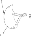
- FIG. 1 is a perspective view of one embodiment 100 of a helmet with an attachment as may be implemented in some embodiments.
- FIG. 1 shows a generic helmet 105 and the activity monitor device 110 mounted on it.
- the device 110 may be mounted on a helmet 105 using bi-adhesive tape, cable plastic strips, compatible custom or industry standard attachments, a purposely pre-designed attachment on the helmet 105 , or can be embedded in the helmet 105 itself, such that the device 110 and/or helmet 105 include a specific housing for the described hardware.
- the device 110 may also be similarly mounted on hats, head bands, backpack shoulder straps, be functionally stored in backpacks, or other gear.
- the device case is shown in the shape of a fin, as an example, but there is no limitation or restriction on the case shape and location on the helmet.
- the device case may be substantially cylindrical, cuboidal, triangular, hexagonal, or any other shape that provides stability, aerodynamic qualities, telecommunication/data transmission qualities and/or other useful or aesthetic qualities.
- the fin may provide aerodynamic qualities facilitating its attachment to the helmet surface without interfering with the user's maneuverability.
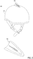
- FIG. 2 illustrates one embodiment 200 of an attachment 502 affixed to a helmet 504 and separate as may be implemented in some embodiments, though the sensor system may be integrated into the helmet or other clothing in some embodiments.
- FIG. 3 is a functional block diagram of a system 300 as may be implemented in some embodiments.
- Dynamic data generated by 9-axis motion sensors (3-axis aceelerometer 33, 3-axis magnetometer 34, 3-axis gyroscope 35 ) and by an atmospheric pressure sensor 36 are supplied continuously to a microcontroller 37.
- the microcontroller 37 may store the data coming from the sensors as well as processed data onto a solid-state non-volatile memory 311 .
- the microcontroller 37 runs software that performs the following a) Continuous monitoring of the motion data from the sensors; b) data analysis and comparison to the specific activity biomechanical model, looking for anomalies; c) In case of an identified anomaly, initiate a decision tree process to identify a potential accidental event; and d) In the case of an accident being identified, decides the optimal strategy to communicate the user location.
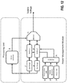
- Communication methods may include, but not be limited to, Bluetooth Low Energy 38 to a smartphone or a cellular network communication module 310 ; satellite transmitter 39 ; or sub-GHz transmitter 312 . Communication strategies will be discussed in further detail below in conjunction with FIG. 18 . Power management by prioritizing use of battery power to privilege safety and prolong battery life in emergency conditions will be discussed in further detail below in conjunction with FIG. 12 .
- the accident detection algorithm may use motion data coming front sensors 33 , 34 , 35 and from the pressure sensor 36 to identify when the same is occurring. Some embodiments will detect any vital sign that indicates an impairment that may inhibit a conscious request for help. For example, such impairments may result from, crashes, collapses, hearth attacks, excessive radiation, submersion, unexpected pressure drops, etc.
- the accident detection algorithm may use data coming from integrated sensors 33, 34 , 35 , 36 or data from other devices communicatively coupled to the system, for example smartwatches, wristbands, chest heartrate monitor, smart rings or other devices.
- the machine learning algorithm in some embodiments is capable of adjusting its parameters based on activity level and user skill level to provide accurate accident recognition while minimizing errors.
- factors relied upon may include: demonstrated speed; tracked figures; successful measured performances like leaning and jumping; and curve trajectories. Such factors are used to change the parameters used in the numerical dynamic model to enhance the identification of the activity anomalies.
- the algorithm may also use machine-iesrnmg techniques to gradually adapt over time to the dynamics typical of each user individually as the user's skills improve or degrade with practice or inactivity, respectively.
- the solid-state non-volatile memory 311 may record the motion data for a configurable length of time. In case of an accident or other event, the memorized data can be made available to qualified rescue personnel to provide detailed information on how the events preceding and following the accident evolved,
- the device presented in some embodiments may be equipped with sub-GHz transmitter 312 that has an approximately four miles to eight miles communication range.
- the device in some embodiments can automatically detect the emergency and send a distress signal, e.g., using the sub-GBz transmitter.
- Other similar devices in the area covered by the distress signal can automatically recognize the help request and alert a second user of an emergency nearby.
- a second computing device communicatively coupled to the system for example a smartphone
- a second user who has received the distress message can locate the source of the call and provide help faster than any other entity who may be far away and/or may have difficult access to the area,
- the device may work in conjunction with a smartphone application
- the application may have an open interface (e.g., an open software interface), be flexible, and may be able to access other external devices that the first user may be carrying and that may collect biometric data (e.g., heart rate, temperature, oxygen levels, motion, etc.).
- biometric data e.g., heart rate, temperature, oxygen levels, motion, etc.
- the application may combine data from the device described elsewhere herein as well. as data from any other supported device, to generate a detailed portrait of the user condition in case of an accident in some embodiments. This information may be made available to qualified rescue personnel to improve rescue efficiency and immediate medical care.
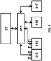
- FIG. 4 is a functional block diagram of a power management system 415 as may be implemented in some embodiments.
- the device can source power from two batteries 413, 414,
- the microcontroller 37 may enable one battery at a time based on a priority system.
- Battery 413 may be used for the normal motion monitoring operations and potentially to control other devices, such as cameras and other functionalities not critical to the safety features of the device.
- Battery 414 is used as an emergency use battery and comes into play only when battery 413 is depleted and in case of an emergency by deactivating any functionality not strictly needed for the management of the emergency.
- An algorithm running on a microcontroller 37 may monitor the status of each battery and may decide when to switch to battery 414 and turn off redundant activities. To guarantee functionality in case of emergency the microcontroller 37 may also enable and control additional power sources in some embodiments, e.g.: a kinetic energy harvester 416 and a photovoltaic system 417.
- the device is to be placed on or integrated into helmets used in various sports or other activities, A power management solution for emergency rescue wearable devices may be provided in some embodiments.
- Wearable devices that aim at improving safety for users may need to guarantee that they will have enough power to operate when they are needed and for the entire duration of the emergency. Thus, power management can be a critical factor affecting reliability of such devices.
- Some embodiments implement a system based upon a multiple battery mechanism and an algorithm that assigns battery resources according to specific priorities. This may ensure that at least one battery will be available in case of an emergency. Some embodiments also adopt energy harvesting techniques (e.g., kinetic and photovoltaic) to exploit motion and light to prolong battery life,
- the first battery may be used for the normal motion monitoring operations, potentially to control other devices, such as cameras and communication modules, and/or as a backup battery.
- the first battery may be used during an emergency in some embodiments when a second battery is depleted.
- the second battery may be used only in case of an emergency.
- An algorithm running on a microcontroller may continuously monitor the energy level of each battery and, based on the amount of remaining charge, decide to disable certain non-essential functionalities to maximize battery life. Certain sensors, for example, may be temporarily disabled if not essential in a specific activity, sampling frequency may be reduced and communication minimized.
- supplemental harvesting techniques e.g.: solar and kinetic.
- the algorithm may optimally manage energy harvesting devices to maximize energy storage efficiency.
- some embodiments implement an algorithm for multi-battery management
- Some embodiments employ a redundant battery architecture.
- Some embodiments employ multi-source energy feeding (e.g., wireless power, solar, kinetics).
- Some embodiments implement in/out energy management gauging and reporting. Some embodiments implement self-sustainable emergency communication device with unlimited operation. In some such embodiments, for example, the implemented combination of energy harvesting and advanced load management may allow the device to send unlimited emergency distress messages virtually with no discontinuation of the service within the lifetime and the operating specifications of the components.
- FIG. 5 is a block diagram illustrating operation of the detection system 500 at a high level as may be implemented in some embodiments.
- sensors 502 in a head-mounted device 502 or third-party device may collect data 506a, 506b, 506c (e.g., gyroscope, compass, acceleration, etc. data) about one or more activities, for example an accident 512, of a user.
- the data is transmitted 511, for example via, e.g., a Bluetooth connection to a mobile phone 508, to contact a second user 513, for example a first responded
- the mobile phone 508 may supplement the data with GPS coordinates and other context information, for example.
- FIG. 6 is a block diagram illustrating operation of the detection system 600 using alternative coverage at a high level as may be implemented in some embodiments.
- sensors 602 on a head-mounted device 604 may collect data 606a, 606b, 606c (e.g.. gyroscope, compass, acceleration, etc. data) about one or more activities, for example an accident 612, of a user.
- the data is transmitted, for example via, e.g., satellite 608, to contact a second user 613, for example a first responder.
- the head-mounted system may include a GPS (or other position) receiver for location coordinates calculation,
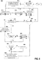
- FIG. 9 is a flow diagram illustrating a process 900 for detecting and responding to an event as may be implemented in some embodiments.
- a user may select the type or character of the activity in which they may engage (e.g., swimming, hiking, biking, etc.). The user may make the selection via, for example a graphical user interface (GUI) on a mobile phone, a switch on the mounted device, a Bluetooth connection etc.
- GUI graphical user interface
- the system may identify the relevant models, algorithms, and sensors for a given selection. For example, a gyroscope may be used when biking, while a temperature sensor and a submersion detection sensor may be used for water rafting,
- the system may supplement the time series of sensor data with new data.
- the system may analyze the data at block 920 to determine if an event has occurred.
- a frequency analysis, a Principal Component Analysis, a threshold model-based analysis, etc, may be used, alone or in combination to identify an event based on the context. For example, a skier's jumps can be easily misread as an indicator that something anomalous happened to the user, but by using different analysis methods we can separate jumping from loss of control flying during the activity.
- the system may prepare a characterization for a second user, for example a first responder. For example, for physical trauma, the system may determine which body parts are most likely injured. For a drowning incident, the system may record GPS coordinates, a depth, a timestamp since the last submersion, etc. Accident identification will be discussed in further detail below in conjunction with FIGS. 14 . 16 .
- the system may begin a notification process.
- the user may indicate a false alarm using a GUI on a mobile phone.
- the system may determine if it can access the mobile phone's network and if so, will communicate the event details to a remote system at block 940 (or an update to a previous submission) to precipitate a first responder response. Conversely, if satellite access is available at block 945, the system may attempt to transmit the information via satellite. If peers are available at block 955, they may likewise be notified of the event at block 960. For example, if the victim is an incapacitated biker, the system may contact the mobile phones and/or devices of other bikers in the area. Sometimes the system can use other devices as a network extender to bounce the request for help through the cellular phone or its satellite communication. This would be particularly useful in case the device is not capable of determining - a position or geographic location to communicate directly with the network of choice.
- the system may take actions anticipating responder arrival (e.g., manage battery power, update the event characterization with new sensor data, etc.).
- a black box update may be prepared so that first responders will have access to the most recent data upon arrival if the device is unable to transmit the data wirelessly. The process may continue until the user or first responder cancels the requests,
- the device may be attached to or integrated into helmets used in sport activities.
- a sport specific accident detection and safety algorithm using dynamic data collected by one or more motion sensors integrated in or mounted on helmet may be used.
- Sport activities often bear a certain level of risk and accidents can happen to anyone. It is of extreme importance to be able to identify when an accident has happened, particularly if the user is practicing the sport alone or out of sight and if the user is unconscious as a result of a fall.
- Some embodiments contemplate a device that includes motion sensors to monitor the user activity and motion dynamics and a microcontroller that runs an algorithm capable of analyzing the data provided by the sensors and detect an accident when that happens.
- the device is placed on or integrated into helmets used in sport activities, including, but not limited to, cycling, mountain biking, skiing, snowboarding, motorcycling, horseback riding.
- the device may include a microcontroller, non-volatile storage memory and the following sensors: 3-axis accelerometer, 3-axis gyroscope, 3-axis magnetometer, and pressure sensor.
- the microcontroller may run firmware that continuously monitors the values provided by the sensors.
- the firmware may also include an algorithm that interprets the data provided by the sensors and is capable of recognizing when an accident is occurring.
- the dynamics may greatly vary depending on the type of activity. Accordingly, the user may specify what type of activity he/she is engaging in and the algorithm will adjust its parameters according to one or more pre-defined models. Over time, the algorithm may tune its internal parameters based on the typical motion patterns of each individual user in order to optimize accident detection capabilities and minimize the chance of false alarms.
- some embodiments apply specific biomechanical models applied to the activity dynamics.
- a machine learning algorithm may be applied for personalized tuning of parameters,
- predictive models for event anticipation and consistency check may be applied.
- data analytics for safety and emergency help requests may be applied.
- Selectable profiles for specific activities and dynamics may be provided in some embodiments. Real time biometric monitoring for rescue intervention, prioritization and efficiency may also be provided in some embodiments.
- FIG. 7 is a block diagram illustrating various components in accident detection and response system 700 as may be implemented in some embodiments.
- a wearable garment e.g., helmet
- one or more communication systems e.g., low energy Bluetooth, satellite, sub-GHz transmitter
- embedded software for analyzing data from the one or more sensors, detecting one or more activities of a user, and/or transmitting the data to a second user.
- one or more computing devices 704 of the system may display or present a GUI with various functionality, For example, may include one or more status icons; a navigation icon; a concierge icon; a checking in icon; one or more locking switches; an emergency contacts icon; a history icon for viewing an activity history; one or more social networking icons for sharing activity information with friends, family, or acquaintances; etc. Still further for example, the system may include one or more additional computing devices 706 configured to present or display additional information which, in some embodiments, may be stored in a personal profile.
- the personal profile may include emergency data storage, activity data analytics (such as but not limited to, speed, acceleration, direction, route, lean angle, jumping angle, time, altitude, force in action, 3D model avatar), adventure planning capabilities, general information about the user (e.g., likes, dislikes, age, educational background, residence location, relationship status, etc.).
- activity data analytics such as but not limited to, speed, acceleration, direction, route, lean angle, jumping angle, time, altitude, force in action, 3D model avatar
- adventure planning capabilities general information about the user (e.g., likes, dislikes, age, educational background, residence location, relationship status, etc.).
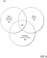
- FIG, 8 is a Venn diagram 800 illustrating various target functionalities met by certain embodiments.
- the embodiments 808 described here lie at the interface between sport consumer electronics 802, safety demand 804, and wearable Internet of Things (IoT) technology 806,
- IoT Internet of Things
- the device is to be placed on or integrated into helmets used in sport activities.
- a multi-seasor architecture and consistency check algorithm of biometric data for unconscious 2-way communication and efficient rescue/emergency intervention are implemented.
- Rescue teams may have a preference for 2-ways communication with accident victims.
- the rescue team may need to assess the situation and the conditions of the user, prioritize their intervention and make sure to be equipped for best efficiency.
- Sensor feedback and monitoring of the user's conditions during the period immediately following an accident can be vital for the successful outcome of the rescue operation.
- Some embodiments seek to consolidate and provide this information in the time following an accident and preceding the arrival of help.
- the rescue personnel can act on the information before leaving, en route, on site, and even following retrieval.
- Some embodiments anticipate a user carrying multiple wearable devices capable of collecting different types of data,
- the data from the tracking devices may be assembled into a sophisticated model that creates a holistic picture of the user condition.
- the model may be open and becomes more accurate and richer the more information is made available through third party devices.
- Such information from third party devices may be transmitted to and/or processed by one or more computing devices, as described elsewhere herein.
- Some embodiments contemplate using multiple sensor data collection and analysis, Some embodiments implement consistency check and reporting and provide a unique intelligent analysis and highlight system. Some embodiments implement encrypted communication and may provide mobile or web access to information through a unique key. Some embodiments provide "black box recording," for example pre- and post-accident event comparison.
- Multi-channel communication strategy for rescue alert Multi-channel communication strategy for rescue alert.
- a multi-channel communication strategy for rescue alert may be used.
- a rescue team may request communication with the user following an accident This may be difficult in remote locations and difficult geographic environments.
- timely distress communication can be critical to maximizing the chances of survival and minimizing damage to the victim.
- Some embodiments combine multiple strategies to optimize the distress communication and to maximize the rescue success rate.
- a smartphone accompanying the victim may be used to deliver the message and/or data to first responders (communicating, e.g., via Bluetooth), If a smartphone is not available, the system may revert to satellite, communication, In case particular topographical conditions prevent satellite accessibility, some embodiments use sub-GHz antennas to establish communication with similar devices that are located within a 50 mile radius of the user, Finally, if these techniques are not available, some embodiments implement a check-in mechanism in which a server will send out an emergency alert automatically if a check-in signal from the user is not received within a predefined amount of time.
- some embodiments provide a communication strategy optimized to maximize success rate based on local conditions, Some embodiments provide a power efficient strategy to maximize batter life, Some embodiments bounce a signal off of neighboring devices to bridge to the closest receiver.
- Timely communication in case of an accident can be critical to maximize survival rate and minimize damage. Often people around the victim of an accident can provide invaluable help until professional rescue teams arrive (e.g., during the "golden hour"). These individuals represent a virtual community immediately available for first assistance. For example, other skiers can be the very first responders to an injured skier, other bikers for a knocked out biker on the curb side, companions and team mates of a climbing adventurer, etc.
- Some embodiments equip devices with sub-GHz capabilities that have an approximately 50 mile range of communication.
- multiple users wearing the devices can automatically detect the emergency and send a distress signal, using a sub-GHz transmitter, between one another.
- Other devices in the area covered by the distress signal can automatically recognize the help request and alert the user of an emergency nearby.
- the user who has received the distress message can locate the source of the emergency message and provide help faster than any other entity that may be farther away and may have difficult access to the area,
- some embodiments provide a peer-to-peer direct communication protocol. Some embodiments provide an in-the-range detection algorithm. Some embodiments provide multiple-variable nodes architecture and network management (e.g., as part of an ad hoc network).
- some embodiments can quickly provide the rescuers with a detailed picture of how the accidental event evolved, how the user moved, what forces were applied to the user's head or body and what happened in the minutes following the trauma. This information can provide rescuers with an amount of objective information that can prove vital in the quick detection of critical traumas.
- a model can be installed on a portable device in the hands of the rescue team that can access the data from the wearable device on, for example, the helmet.
- the rescuer's device may graphically reproduce the traumatic event for a quick assessment of the damage (e.g., indicating which portion of the victim's anatomy was affected).
- Some embodiments implement a dynamic numerical model for the specific discipline practiced (e.g., skiing, swimming, etc.), as described in further detail elsewhere herein.
- System models may be able ro precisely quantify the entity and quality of traumas.
- Entity is defined by the direction of the forces applied during the accident or other information available to the system.
- the heart rate monitor can clearly indicate that the primary reason of the accident is a heart attack, absence of such alteration may imply a mechanical cause of trauma.
- Quality is defined by the magnitude of the forces registered during the event or other information available. For example, the record of 60g force may identify a very serious impact, a low body temperature may identify a dramatic hypothermia developing scenario, or a high or irregular heart rate may quantity the level of physical distress of the user.
- Some embodiments implement a black-box approach for sport accidents and related injuries.
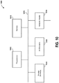
- FIG. 10 is a block diagram of a computer system 1000 as may be used to implement features, e.g., navigation, object recognition, preprogrammed behavior, of some of the embodiments.
- the computing system 1000 may include one or more central processing units ("processors") 1005, memory 1010, input/output devices 1025 (e.g., keyboard and pointing devices, display devices), storage devices 1020 (e.g., disk drives), and network adapters 1030 (e.g., network interfaces) that are connected to an interconnect 1015.
- the interconnect 1015 is illustrated as an abstraction that represents any one or more separate physical buses, point to point connections, or both connected by appropriate bridges, adapters, or controllers.
- the interconnect 815 may include, for example, a system bus, a Peripheral Component Interconnect (PCI) bus or PCI-Express bus, a HyperTransport or industry standard architecture (ISA) bus, a small computer system interface (SCSI) bus, a universal serial bus (USB), HC (I2C) bus, or an Institute of Electrical and Electronics Engineers (IEEE) standard 1394 bus, also called "Firewire”.
- PCI Peripheral Component Interconnect
- ISA industry standard architecture
- SCSI small computer system interface
- USB universal serial bus
- I2C universal serial bus
- IEEE Institute of Electrical and Electronics Engineers
- the memory 1010 and storage devices 1020 are computer-readable storage media that may store instructions that implement at least portions of the various embodiments.
- the data structures and message structures may be stored or transmitted via a data transmission medium, e.g., a signal on a communications link.
- a data transmission medium e.g., a signal on a communications link.
- Various communications links may be used, e.g., the Internet, a local area network, a wide area network, or a point-to-point dial-up connection,
- computer readable media can include computer-readable storage media (e.g., "non transitory” media) arid computer-readabie transmission media.
- the instructions stored in memory 1010 can be implemented as software and/or firmware to program the processor(s) 1 005 to carry out actions described above, In some embodiments, such software or firmware may be initially provided to the processing system 1000 by downloading it from a remote system through the computing system 1000 (e.g., via network adapter 1030 ).
- programmable circuitry e.g., one or more microprocessors
- special-purpose hardwired circuitry may be in the form of, for example, one or more ASICs, PLDs, FPGAs, etc.
- FIG. 11 is a block diagram of a system as may be implemented in some embodiments.
- Motion sensors such as, but not limited to, a 3-axis accelerometer 1, a 3-axis gyroscope 2 and a 3-axis magnetometer 3 transmit dynamic data to a processing unit or microcontroller 8.
- Additional sensors may also be present in the system, including environmental sensors (e.g., a barometer 4, humidity sensor, or temperature sensor 5 ) and biometric sensors (e.g., a body temperature sensor 5, heart rate sensor 6, or other sensor(s) 7, etc.). These additional sensors, when present, also transmit the measured data to the processing unit or microcontroller 8 for further analysis and action.
- the processing unit 8 runs firmware that performs the following tasks:
- Motion, environmental, and biometric sensors 1-7 are connected to the processing unit 8, as depicted in FIG. 11 , Data coming from sensors is typically affected by noise due to intrinsic sensor drift, calibration errors, and interference effects. As a result, the processing unit may adopt filtering procedures to remove undesirable noise from the sensor readings. For example, the system may apply Adaptive, Multirate, Infinite Impulse Response (HR), and Finite Impure Response (FIR) filters to the received sensor data. In the event that the sensors' output is analog, the processing unit performs an analog-to-digital conversion operation. To perform such conversion, the processing unit 8 may include or access an analog-to-digital converter (ADC).
- ADC analog-to-digital converter
- the data stored in the non-volatile memory 9 provides a log of selected metrics concerning the activity of the user.
- the identity of and frequency of collection of metrics tracked by the system is configurable, and can include linear acceleration and angular velocity of the user at different time intervals.
- the non-volatile memory 9 may be managed as a circular buffer in which, when the total capacity is reached, the system overwrites the oldest data with new incoming data.
- the memory is sized, however, in a fashion to ensure that a sufficient time span of data for accident assessment is stored at all times. For example, the system may always store 30 minutes of data representing the user's most recent motion. It will be appreciated that the system may store data representing a greater or lesser amount of time, depending on memory size and frequency and amount of data being stored.
- Data stored in the non-volatile memory can be transmitted to an external device (e.g., a smartphone or tablet) via the BLE module 10 or via any other available wireless or wired channel.
- the monitored data is used to create a model of the user activity, including information such as lean angles, trajectory, velocity, etc. of the user,
- the stored data can also be used, in the case of an emergency, by rescue teams, providing them with a deeper understanding of the dynamics leading to the accident and guiding emergency responders towards the adoption of the most appropriate intervention measures.
- the processing unit 8 and the firmware running on it identify a potentially dangerous accident involving the user when it occurs.
- Accident detection is achieved by continuously monitoring data from the sensors and by using the data to create a biomechanieal model of the user engaged in his/her activity.
- the biomechanical model represents the motion of the user white engaged in the activity.
- the system uses the biomechanical model to determine when the behavior of the user diverges from the expected behaviors typical of the associated activity. That is, the accident detection algorithm executed by the processing unit 8 is tailored to different activities (e.g., skiing, snowboarding, road cycling, mountain biking, etc.) because each activity is characterized by peculiar dynamics and behaviors that do not necessarily apply to others.
- the identification of the activity being performed can either be provided explicitly by the user or automatically detected by the system itself, through its activity recognition capabilities.
- the algorithm compares parameters from the biomechanical model with expected parameter values for the activity.
- the divergence of parameter values from the biomechanical model with the expected parameter values for the activity can suggest a potential accident.
- a subsequent analysis stage is activated to closely monitor all sensor data to determine if an accident has in fact happened.
- the system can detect not only an impact indicated by a sudden stop but other emergencies not including an impact. For example, the system would also detect if a user had a heart attack while motorcycling and slowly coasted to a stop and then passed out at the side of the road.
- the system alerts the user through a visual and audible signal as well as via a message alert on an external device (e.g., a smartphone).
- an external device e.g., a smartphone.
- the user is given a pre-determined amount of time to confirm that no injury has been sustained and cancel the help request. If no action is taken by the user within the pre-determined time interval, the system determines the optimal strategy to communicate a help request to a list of selected users or emergency responders.
- the communication strategy is based on the prioritization of the available resources. For example. if the system contains a sub-GHz radio module 11, the radio module is triggered first because it could potentially reach other users that are closest to the victim and hence in a position to provide immediate assistance.
- the system attempts to connect to an available smartphone to determine whether there is service coverage. If service coverage exists, the smartphone is used by the system to send the help request to pre-selected contacts and/or emergency respondent If no service coverage is present or no smartphone is available (e.g., the smartphones battery is drained, the smartphone is damaged), the system attempts to use a satellite transmitter module 12 to send the help request. If the satellite transmitter 12 is available, then the system sends the help request through satellite communication. If neither smartphone nor satellite transmitter is available, the system will continue to repeat a polling cycle of the communication channels at variable or fixed time intervals, to assess whether any of the channels become available. Once a channel becomes available, the help request is sent.
- the help request sent by the system may contain a variety of information that is helpful to first responders.
- the help request typically includes the GPS coordinates of the user to aid first responders in locating the user.
- biometric or environmental sensor data is available, certain sensor data can also be sent as the data can be relevant to help emergency responders form a clearer picture of the accident scene and the victim's physical conditions. If a camera and/or a microphone are available, data coming from these components can be saved in the storage module and conveyed in the help request to provide additional detail that complements the overall description of the accident and the victim to rescue personnel.
- the help request may be a text message, an email message, a proprietary-format message, or other communication that conveys the necessary information to those who can assist the user.
- the communication module and/or I/O module can emit signals (e.g., light via LEDs 16; radio signals via BLE module 10 and/or radio module 11 ) to act as a beacon for emergency responders,
- the system implements a rigorous power management policy.
- the system uses a dual battery architecture in which one of the batteries 19 is the main power source and is used for all the regular operations (e.g., activity monitor, data transmission, communication, powering of a camera if available).
- a second battery 20 is a backup power source and is reserved for emergency situations.
- the system regularly monitors the charge level of the main battery using monitoring circuits 17,18 and, as the charge decreases, implements power saving strategies to maximize battery life. Some non-vital functionalities may be disabled or reduced when the main battery charge level decreases beyond a pre-set threshold.
- the system may disable all non-critical functions to guarantee that enough power is available to sustain monitoring and communication capabilities until assistance is provided to the user.
- motion sensing features may remain operational, although at a reduced frequency of sensing, to detect activity of the victim.
- Communication is activated at regular time intervals to maximize the likelihood of the help request reaching the destination.
- other power sources may be included, such as photovoltaic cells 22 and kinetic energy harvesters 23 . Energy derived from light or motion may be used by a harvester 25 to recharge batteries 19 and 20.
- a micro USB port is provided to allow a user to directly charge batteries 19 and 20 when an external power source is available.
- the system does not communicate with external devices unless an accident is detected.
- the system can be reached and controlled by authorized external devices, such as smartphones, smartwatches or tablets, using a Bluetooth or other dear-field communication (NFC) connection.
- the external devices can instruct the system to transmit raw data from the sensors as well as a number of other processed information, such as quaternions or Euler's angles, that can be used by the external smart devices for advanced modeling and activity analysis.
- the data may be accessed for subsequent performance analysis of the activity or to generate 3D visualizations of the activity that can be shared with friends and family.
- the content of the non-volatile memory 9 can be transferred to other devices. For example, rescue teams can access the system and use information stored in the memory 9 as a black-box recording, providing detailed information of the dynamics before, during and after the accident.
- the system executes processes described in FIG. 13 - FIG. 18 to identify an accident and to verify if, as a consequence of the accident, the user/wearer of the system is unable to ask for help.
- An automatic request for help is triggered by the system if an accident is detected and the user does not disable or otherwise prevent transmission of the help request within a certain period of time.
- One advantage of the disclosed accident detection process is that for an accident to be recognized it doesn't necessarily require a physical impact of the helmet or an extreme angular velocity measured outside of specific thresholds.
- the disclosed system is thereby able to identify accidents like, for example, falls as a result of a heart attack, heat stroke, or other accident not implying a head hit.
- the accident detection algorithm implemented by the system encompasses three specific stages: (1) activity identification, (2) activity monitoring including anomalous/potential accident event identification, and (3) assessment of user condition and accident confirmation. Each stage will be described in additional detail herein.
- FIG. 13 is a flow diagram illustrating a process implemented by the system for recognizing an activity, the first stage of the accident detection algorithm.
- the user Before the beginning of an activity, at decision block 49 the user has the option to specify the type of activity he/she is going to engage in (e.g., motorcycling, road biking, skiing, etc.).
- a user can specify the activity through a software application running on an authorized device that communicates with the system, such as a smartphone or tablet.
- the user may be presented with a drop down menu or radio buttons associated with potential activities, from which an activity is selected, Alternatively, the activity monitor device 105 may have physical buttons or offer other input functionality to allow the user to select the activity.
- the activity selection is particularly recommended for new users, until the system has the opportunity to monitor the user and derive an understanding of the typical activity profile of the user.
- the system attempts to automatically identity the activity type by analyzing a set of parameters in blocks 50-53 .
- the parameters analyzed by the system may include, but are not limited to, location (e.g., altitude, latitude, longitude), physical constraints (e.g., on the road, off road), terrain (e.g., ski resort, park, beach, desert), speed (e.g., ski typical values, biking typical values, motorcycling typical values), acceleration patterns (e.g., gravity acceleration on a slope, motor accelerations, human propelled accelerations), trajectory patterns (e.g., curves radius, lean angle, point of sensing height), relative spatial position and movements, and biomechankal patterns (compared with historical value registered by the user).
- location e.g., altitude, latitude, longitude
- physical constraints e.g., on the road, off road
- terrain e.g., ski resort, park, beach, desert
- speed e.g., ski typical values, biking typical values, motorcycling typical values
- the adoption of the correct activity biomechanical model is important for accurate accident identification.
- the activity biomechanical model is a simplified representation of the human body while performing the corresponding activity.
- An example of an activity biomechanical model used by the system is an Inverted Pendulum model, complemented with additional information regarding, for example, the position of the sensor (e.g., on the back of a skier or on the helmet of a biker) and user biometrics (height, weight, age).
- Some key parameters and assumptions drive the creation of the biomechanical model
- Some examples include the degrees of freedom of the Inverted Pendulum, the distribution of masses, typical or expected position, center of mass position, point of contacts with the ground, friction/viscosity of the ground, etc.
- the system reads motion sensor data (e.g., accelerometer, gyroscope, magnetometer) and calculates certain derived values (e.g., user orientation, position, linear velocity) from the motion sensor data.
- the system obtains GPS coordinates of the user either from an on-hoard GPS module or from a GPS module included in a connected smart device (smartphone, smartwatch, tablet, etc.). Barometer values are also read by the system. The combination of GPS and barometer readings is used by the system to obtain the accurate geographic location of the user. By locating the user on a digital topographic map it is possible to obtain information about the type of terrain surrounding the user. The surrounding terrain gives clues to the system about likely activities in which the user is engaged.
- the system analyzes the values of the motion sensors for a predefined time window to extract a pattern.
- the pattern is compared by the system with a library of pre-determined patterns that uniquely identify each activity (e.g., skiing, motorcycling, road biking, etc.). If a pattern match is found consistent with the other analyzed data (e.g., the user location), then the activity is identified. Otherwise the system continues monitoring the user until an activity match is found.
- the activity analysis routine runs in the background until the probability of activity identification is at least 90%, 95%, or 98%.
- the activity recognition process enables the system to select the right activity biomechanical model for purposes of the accident detection stage.
- the season can also be used by the system in order to assess the activity of the user.
- the system may maintain a calendar date or may receive a calendar date from a linked mobile phone, smartwatch, or other authorized device.
- the season can be used in conjunction with the GPS data to select certain activities over others (e.g., hiking in the mountains in the summer months vs. skiing in the mountains in the winter months).
- FIG. 14 is a flow diagram illustrating a process implemented by the system for identifying an accident.
- Inputs to the accident detection algorithm are: the activity type as provided by the user or assessed by the system; sensor readings as provided by on-board sensors; and, optionally, biometrics data (e.g., user height, weight, age, skill-level), may be provided by the user.
- the user may provide the biometrics data through a graphical user interface on an authorized device (e.g., a smartphone) coupled to the system.
- an authorized device e.g., a smartphone
- the system reads the sensor values and calculates certain derived values from the sensor date.
- the combination of both read and derived values is used by the system at block 54 to build a time-dependent, multi-dimensional biometric vector that describes the motion, the position, and orientation of the user at any given time interval
- a representative biomechanical model used by the system is shown by a time- dependent matrix in FIG. 15 .
- A is the acceleration vector from the accelerometer
- ⁇ the angular velocity given by gyroscope
- M the magnetic orientation vector from the magnetometer
- Lt is the geographic latitude and Lg is the geographic longitude from the GPS
- H is the altitude from the barometer
- ( X,Y,Z ) is the relative position
- V is the velocity vector
- F is the force vector
- ⁇ is the angular acceleration
- L is the angular momentum vector.
- Position X (t) the position location may be periodically compared to GPS geolocalization in order to improve overall accuracy
- the matrix provides instantaneous information on the user's activity and is used by the system at block 55 to build vector patterns - defined as a sequence of vectors over a period of time - that characterize the activity under analysis.
- the obtained sequence of vectors is stored by the system in non-volatile memory 9. Because the sensors values as well as the derived values for each time interval are stored in the non-volatile memory 9, it is possible for the system to retrieve the stored values to calculate the trajectory and the evolution over a given time interval of the user activity. Such information supports the accident detection analysis performed by the system.
- the system maintains a library of values and vector patterns that characterize different activity.
- a pattern is a sequence of vectors over time.
- the library of vector patterns reflect typical or "normal" motion associated with various activities (e.g., skiing, biking, running).
- the library of vector patterns may also be associated with a level of mastery or activity approach (e.g., expert, intermediate, or beginner skier, or aggressive, average, or relaxed skier). For example, the more the athlete is proficient with acrobatic skiing, the more patterns associated with jumps and acrobatic figures will populate the library.
- the library is automatically updated over time either from external input, but also from the patterns automatically generated by the system as it monitors the activity. By modifying the stored patterns that characterize each sport activity, the system is allowed to "learn" from the user's habits and become better adapted to the user's activities.
- the system compares the monitored motion of the user with stored vector patterns that characterize "normal" parameters associated with the corresponding activity. In order to make such a comparison, the system performs one or more of the following three validity tests:
- the system treats such failure as a potential accident. To confirm that an accident has indeed occurred, however, the system progresses to a third stage of accident analysis.
- the patterns are associated with properties that represent the probability that the pattern will occur and the probability that the pattern represents a potential accident
- the system adapts to the athlete proficiency, conditions, and shape. For example, at the beginning of the season a user may not be in good shape and in great form, so certain patterns may not be utilized for purposes of the comparison, but as training progresses more advanced patterns may be used by the system.
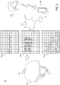
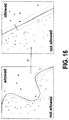
- FIG. 16 A bi-dimensional representation of how the system evolves and learns over time is illustrated in FIG. 16 .
- Biomechanical vectors are represented by points and a solid line separates values that are "allowed” (i.e., safe, and not indicative of a potential accident) from values that are "not allowed” (e.g., may indicate a hazard condition).
- allowed vectors are depicted with solid points and not allowed vectors are depicted with hollow points.
- the border between the regions changes, learning and adapting to the user behavior. Since the matrix is multidimensional, the same concept must be translated into a multidimensional space.
- FIG. 17 is a flow diagram illustrating a process that is implemented by the system to verily that an accident has occurred.
- the system not only identifies the occurrence of an accident, but also assess whether the user is incapacitated (as a result of an accident or other reasons) and as such unable to autonomously call for help.
- the accident detection stage ( FIG. 14 ) indicates that a potential accident has occurred, the system only knows that an anomalous event that does not match with allowed patterns has been identified.
- the anomalous event may or may not reflect an actual accident.
- a user-defined time window is therefore used to monitor activity following the detection of a potential accident, and to establish with sufficient confidence that a severe accident has occurred.
- the system implements the decision tree analysis depicted in FIG . 17 as part of a third stage of accident analysis.
- the sensor data provides sufficient information for the system to answer questions that reflect the state of the user, such as: Has the original activity resumed? Is the user moving or not moving? Is the movement linear or random or shaking? Is the helmet worn or not? Is the system still attached to the helmet or not? What is the user position? Orientation? Was any sharp change in the altitude measurement detected? Any abrupt change in velocity or acceleration? Was any peak force applied? Did we measure any up-side down evolution? Any flying dynamics?
- biometric sensors e.g., heart rate monitor, body temperatures, etc.
- readings from the biometric sensors may be included as part of the decision tree analysis. Anomalies in biometric readings can provide useful data on the event and on the user condition. For example, if the system has biometric data, the system can assess questions like: What's the heart rate of the user? What's the body temperature of the user?
- the system implements the following decision tree analysis.
- the system calculates the past trajectory of the user based on stored sensor data. Because all sensor values as well as the derived values for each time interval are stored in the non-volatile memory, the system can retrieve the stored values and calculate the trajectory of the user and the evolution over a given time interval of the user dynamics.
- various parameters associated with the current state of the user are assessed.
- the system continues to monitor current values from the sensors. Sensor values are continuously read and derived values are calculated to assess current activity of the user.
- the user position e.g., standing or laying
- orientation are calculated based on sensor readings. Both the activity and position of the user may be calculated by the system at certain time intervals.
- the system assesses the evolution of certain parameter values over time windows that extend in the past (from recorded values) and continue in the present to determine whether sudden changes in values (e.g., position, acceleration, orientation) suggest that a potentially traumatic event may have occurred.
- sudden changes in values e.g., position, acceleration, orientation
- biometric sensors e.g., heart rate monitor, body temperatures, etc.
- readings from the biometric sensors may be gathered by the system and included as part of the decision tree analysis. Anomalies in biometric readings can provide useful data on the event and on the patient condition.
- the motion sensor readings are continuously monitored by the system to detect whether user activity resumes (after a fall, for instance) and the quality of the activity (is it a regular motion, e.g., walking or erratic movements?).
- the event is considered non-critical (or at least the user is conscious and capable of calling for help independently) and the process returns to block 57 to continue to monitor user activity.
- the system continues to monitor until a pre-defined monitoring time window has elapsed.
- the monitored time window may range, for example, from 30-300 seconds or more.
- the monitored time window may vary depending on the activity of the user and the likelihood of a serious accident occurring as a result of that activity.
- a final analysis of the recorded parameters is assessed to confirm that an accident condition likely exists. If, for example, a sudden change in acceleration is determined, with a corresponding equally sudden change in user position and absence of movement afterwards then these - after the monitoring phase at the previous steps has completed - are considered a clear indication of a severe accident.
- processing continues to block 66.
- the system activates an alert count down, with an audio and visual alert, to give the user a final chance to stop a help request from being sent.
- the countdown reaches zero, the help request is sent following the communication strategy described in FIG. 18 .
- the user is provided the ability to stop the help request within a certain, period of time (for example, by default 30 seconds). In some embodiments, the period of time is user-customizable, manufacturer specified, or predefined.
- the system instead determines that no accident occurred, the registered pattern associated with the decision tree analysis is added to the patterns library with its own recurrence value equal to 1 to indicate a low probability event. In this manner, if the user is particularly keen in acrobatic jumps and figures, motion patterns associated with those actions will be included in the library and not be considered events to be identified as potential accidents. Also if the user stops enjoying acrobatic jumps and figures, the system associates these activities with time lower probability until the pattern of such events will fade away.
- FIG. 18 is a flow diagram illustrating a communication strategy implemented by the system.
- a help request is transmitted via sub-GHz radio (blocks 68 and 72 ) if available. Further, the request is also transmitted via smartphone if the smartphone has coverage (blocks 69 and 74). If not, then the request is transmitted via satellite radio (blocks 70 and 75 ). The process loops repeatedly to send help requests as described above.
- FIG. 19 is a perspective view of a system as may be implemented in some embodiments.
- the system of FIG. 19 is integrated with LEDs 16, camera 13, microphone 14, environmental sensors 21 (e.g., temperature, pressure), photovoltaic panels 22 to generate electricity, biosensors 27 (e.g., heart rate, etc.), and/or wireless power coil 29 for wireless charging.
- environmental sensors 21 e.g., temperature, pressure
- photovoltaic panels 22 to generate electricity
- biosensors 27 e.g., heart rate, etc.
- wireless power coil 29 for wireless charging.
- the system is a single piece with the sensors and modules etc integrated therein.
- the system may be integrated into a helmet or other piece of gear to prevent separation of the sensors/modules etc. in the event of an accident and to help ensure that the system continues to function.
- the system can be integrated into clothing (vest, jacket), boots, wristband, gloves, etc.
- the systems and methods of the preferred embodiment and variations thereof can be embodied and/or implemented at least in part as a machine configured to receive a computer-readable medium storing computer-readable instructions.
- the instructions are preferably executed by computer-executable components preferably integrated with the system and one or more portions of a processor in a computing device.
- the computer-readable medium can be stored on any suitable computer-readable media such as RAMs, ROMs, flash memory, EEPROMs, optical devices (e.g., CD or DVD), hard drives, floppy drives, or any suitable device.
- the computer-executable component is preferably a general or application-specific processor, but any suitable dedicated hardware or hardware/firmware combination can alternatively or additionally execute the instructions.
- the singular form “a”, “an” and “the'” include both singular and plural references unless the context clearly dictates otherwise.
- the term “sensor” may include, and is contemplated to include, a plurality of sensors.
- the claims and disclosure may include terms such as “a plurality,” “one or more,” or “at least one;” however, the absence of such terms is not intended to mean, and should not be interpreted to mean, that a plurality is not conceived.
- the term “comprising” or “comprises” is intended to mean that the devices, systems, and methods include the recited elements, and may additionally include any other elements.
- Consisting essentially of' shall mean that the devices, systems, and methods include the recited elements and exclude other elements of essential significance to the combination for the stated purpose. Thus, a system or method consisting essentially of the elements as defined herein would not exclude other materials, features, or steps that do not materially affect the basic and novel characteristic(s) of the claimed disclosure.
- Consisting of shall mean that the devices, systems, and methods include the recited elements and exclude anything more than a trivial or inconsequential element or step. Embodiments defined by each of these transitional terms are within the scope of this disclosure.
Landscapes
- Health & Medical Sciences (AREA)
- Life Sciences & Earth Sciences (AREA)
- Physics & Mathematics (AREA)
- Engineering & Computer Science (AREA)
- General Health & Medical Sciences (AREA)
- Animal Behavior & Ethology (AREA)
- Public Health (AREA)
- Pathology (AREA)
- Veterinary Medicine (AREA)
- Biomedical Technology (AREA)
- Heart & Thoracic Surgery (AREA)
- Medical Informatics (AREA)
- Molecular Biology (AREA)
- Surgery (AREA)
- Biophysics (AREA)
- Physiology (AREA)
- Dentistry (AREA)
- Oral & Maxillofacial Surgery (AREA)
- Alarm Systems (AREA)
- Business, Economics & Management (AREA)
- Emergency Management (AREA)
- General Physics & Mathematics (AREA)
- Gerontology & Geriatric Medicine (AREA)
- Computer Networks & Wireless Communication (AREA)
- Multimedia (AREA)
- Computer Security & Cryptography (AREA)
- Psychiatry (AREA)
- Psychology (AREA)
- Social Psychology (AREA)
Claims (8)
- Système de réponse d'urgence (100) comprenant :une pluralité de capteurs (33, 34, 35, 36) ;un processeur (37)un module de communication (310) ; etune mémoire (311) comprenant des instructions configurées pour amener le processeur (37) à :acquérir (50) des données de capteur de mouvement d'un utilisateur à partir de la pluralité de capteurs et calculer des valeurs dérivées à partir des données de capteur de mouvement,obtenir (51) les coordonnées GPS de l'utilisateur et une lecture du baromètre pour déterminer une localisation géographique de l'utilisateur,analyser (52) les valeurs dérivées des capteurs de mouvement pour une fenêtre temporelle prédéfinie pour extraire un motif,identifier (53) une activité de l'utilisateur en comparant le motif avec une bibliothèque de motifs prédéterminés qui identifie de manière unique chaque activité, la bibliothèque comportant des motifs vectoriels de mouvement normal et des motifs vectoriels associés à un niveau de maîtrise,générer (54) un vecteur biomécanique multidimensionnel dépendant du temps qui décrit un mouvement, une position et une orientation de l'utilisateur à tout intervalle de temps donné,construire (55) des motifs vectoriels basés sur l'activité pour caractériser l'activité,dans lequel un motif vectoriel est défini comme une séquence de vecteurs sur une période de temps, les stocker dans une mémoire non volatile (9),comparer (56) le mouvement surveillé de l'utilisateur avec les motifs vectoriels stockés,détecter un événement anormal où le mouvement surveillé ne correspond pas aux motifs vectoriels stockés,calculer (57) une trajectoire passée de l'utilisateur basée sur des données de capteur stockées,surveiller (58) les valeurs actuelles de la pluralité de capteurs,calculer (59) la position et l'orientation de l'utilisateur,évaluer (60) une évolution de certaines valeurs de paramètres à partir des valeurs enregistrées et des valeurs actuelles de la pluralité de capteurs pour déterminer si des changements soudains de position, d'accélération et d'orientation indiquent un événement traumatique,détecter (62), à l'aide des lectures du capteur de mouvement, si l'activité de l'utilisateur reprend,si le mouvement de l'utilisateur n'a pas repris et qu'une fenêtre temporelle de surveillance prédéfinie s'est écoulée (65), analyser les valeurs enregistrées pour confirmer que l'événement traumatique s'est produit,activer (66) un compte à rebours d'alerte, avec une alerte audio et visuelle, pour donner à l'utilisateur une dernière chance d'arrêter l'envoi d'une demande d'aide ; etlorsque le compte à rebours de l'alerte atteint zéro, transmettre une demande d'aide à un système distant.
- Système selon la revendication 1, dans lequel l'identification de l'activité de l'utilisateur comprend la détermination de l'emplacement géographique de l'utilisateur et la comparaison de l'emplacement géographique à une carte pour déterminer le terrain et une activité associée pour ce terrain.
- Système selon la revendication 1, dans lequel la mémoire comprenant des instructions est en outre configurée pour amener le processeur (37) à transmettre la demande d'aide par l'intermédiaire d'un ou plusieurs canaux de communication en fonction de la disponibilité des canaux.
- Système selon la revendication 1, comprenant en outre : des première et seconde sources d'alimentation (413, 414) ; et un module de gestion d'alimentation couplé aux deux sources d'alimentation, le module de gestion d'alimentation étant configuré pour amener le système principalement à fonctionner sur la première source d'alimentation (413) et maintenir la seconde source d'alimentation (414) en réserve pour la transmission de la demande indiquant la détection de l'événement traumatique.
- Système selon la revendication 1, dans lequel la génération du vecteur biomécanique multidimensionnel dépendant du temps comprend la mesure ou la dérivation d'un ou de plusieurs parmi: un vecteur d'accélération, un vecteur d'orientation magnétique, une latitude géographique, une longitude géographique, une altitude, une position relative, un vecteur vitesse, un vecteur force, une accélération angulaire, et un vecteur moment angulaire.
- Système selon la revendication 1, dans lequel la mémoire comprenant des instructions est en outre configurée pour amener le processeur à transmettre (67) la demande par l'intermédiaire d'une radio sub-GHz si disponible et si le compte à rebours d'alerte s'est écoulé.
- Système selon la revendication 6, dans lequel la mémoire comprenant des instructions est en outre configurée pour amener le processeur à transmettre en outre (69) la demande par l'intermédiaire d'un smartphone si le smartphone a une couverture.
- Système selon la revendication 1, dans lequel la mémoire comprenant des instructions est en outre configurée pour amener le processeur à transmettre (70) la demande par radio satellite lorsque la radio sub-GHz et la couverture smartphone ne sont pas disponibles.
Applications Claiming Priority (3)
| Application Number | Priority Date | Filing Date | Title |
|---|---|---|---|
| US201462088466P | 2014-12-05 | 2014-12-05 | |
| US14/961,820 US9861151B2 (en) | 2014-12-05 | 2015-12-07 | Activity monitoring systems and methods for accident detection and response |
| PCT/US2016/063821 WO2017100025A1 (fr) | 2014-12-05 | 2016-11-28 | Systèmes et procédés de surveillance d'activités pour la détection d'accidents et la fourniture d'une réponse |
Publications (3)
| Publication Number | Publication Date |
|---|---|
| EP3387630A1 EP3387630A1 (fr) | 2018-10-17 |
| EP3387630A4 EP3387630A4 (fr) | 2019-08-07 |
| EP3387630B1 true EP3387630B1 (fr) | 2021-09-22 |
Family
ID=56111727
Family Applications (1)
| Application Number | Title | Priority Date | Filing Date |
|---|---|---|---|
| EP16873595.9A Active EP3387630B1 (fr) | 2014-12-05 | 2016-11-28 | Systèmes de surveillance d'activités pour la détection d'accidents et la fourniture d'une réponse |
Country Status (4)
| Country | Link |
|---|---|
| US (1) | US9861151B2 (fr) |
| EP (1) | EP3387630B1 (fr) |
| CN (1) | CN108369765B (fr) |
| WO (1) | WO2017100025A1 (fr) |
Cited By (1)
| Publication number | Priority date | Publication date | Assignee | Title |
|---|---|---|---|---|
| TWI848479B (zh) * | 2022-11-16 | 2024-07-11 | 鴻海精密工業股份有限公司 | 定位異常檢測方法、裝置、電子設備及存儲介質 |
Families Citing this family (76)
| Publication number | Priority date | Publication date | Assignee | Title |
|---|---|---|---|---|
| US9569951B2 (en) | 2013-03-27 | 2017-02-14 | Choprix Llc | Emergency notification apparatus and method |
| US9922536B2 (en) | 2014-03-27 | 2018-03-20 | Choprix Llc | Helmet and method of use for emergency notification |
| US10515372B1 (en) | 2014-10-07 | 2019-12-24 | State Farm Mutual Automobile Insurance Company | Systems and methods for managing building code compliance for a property |
| US9861151B2 (en) * | 2014-12-05 | 2018-01-09 | SaPHIBeat Technologies, Inc. | Activity monitoring systems and methods for accident detection and response |
| DE102015216436A1 (de) * | 2015-08-27 | 2017-03-02 | Bayerische Motoren Werke Aktiengesellschaft | Schutzhelm mit aerodynamischem Stabilisierungselement |
| US11497964B1 (en) * | 2015-09-17 | 2022-11-15 | Canary Medical Switzerland Ag | Devices, systems and methods for using and monitoring sports equipment and sports activities |
| US11258366B2 (en) | 2015-11-20 | 2022-02-22 | Galvion Soldier Power, Llc | Power manager with reconfigurable power converting circuits |
| AU2016355125A1 (en) | 2015-11-20 | 2018-07-05 | David Long | Power manager with reconfigurable power converting circuits |
| CN108601416A (zh) * | 2016-02-11 | 2018-09-28 | 哈曼贝克自动系统股份有限公司 | 具有自动应急处理的头盔 |
| CN105575048B (zh) * | 2016-02-25 | 2018-10-02 | 京东方科技集团股份有限公司 | 低头转头提醒装置及其控制方法、头盔 |
| US11125885B2 (en) * | 2016-03-15 | 2021-09-21 | Hand Held Products, Inc. | Monitoring user biometric parameters with nanotechnology in personal locator beacon |
| EP3229183A1 (fr) * | 2016-04-08 | 2017-10-11 | MOBA - Mobile Automation AG | Dispositif et procede de surveillance de donnees de processus pour la fabrication de route |
| DE102016207238A1 (de) * | 2016-04-28 | 2017-11-02 | Siemens Aktiengesellschaft | Verfahren und Vorrichtung zum Löschen von sicherheitsrelevanter Information in einem Gerät |
| IT201600073188A1 (it) * | 2016-07-13 | 2018-01-13 | Gabriel Emanuel Chirila | Dispositivo copricapo intelligente |
| KR102196380B1 (ko) * | 2016-07-21 | 2020-12-30 | 매직 립, 인코포레이티드 | 사용자의 감정 상태들을 사용하여 가상 이미지 생성 시스템을 제어하기 위한 기술 |
| US10690493B2 (en) * | 2016-08-18 | 2020-06-23 | Myriad Sensors, Inc. | Wireless sensor device and software system for measuring linear position of a rotating object |
| GB201619800D0 (en) * | 2016-11-23 | 2017-01-04 | Curamicus Ltd | System and method for user mobility monitoring |
| CN206365527U (zh) * | 2016-12-09 | 2017-08-01 | 点子建有限公司 | 一种集成智能头戴式设备 |
| US10325471B1 (en) * | 2017-04-28 | 2019-06-18 | BlueOwl, LLC | Systems and methods for detecting a medical emergency event |
| US10244581B2 (en) | 2017-05-19 | 2019-03-26 | At&T Mobility Ii Llc | Public safety analytics gateway |
| GB2563408A (en) * | 2017-06-14 | 2018-12-19 | Speedy Quarks Ltd | Smart safety and environmental monitoring helmet |
| US10306341B2 (en) * | 2017-06-28 | 2019-05-28 | Motorola Solutions, Inc. | Method and apparatus for determining sensor data reliability at an incident scene for real-time and post-incident processing |
| JP7136099B2 (ja) * | 2017-07-14 | 2022-09-13 | ソニーグループ株式会社 | 情報処理装置、情報処理方法、およびプログラム |
| DE102017222239A1 (de) * | 2017-12-08 | 2019-06-13 | Bayerische Motoren Werke Aktiengesellschaft | Schutzhelm mit Bluetooth-Antenne |
| USD890436S1 (en) * | 2017-12-28 | 2020-07-14 | ABUS August Bremicker Söhne KG | Bicycle helmet |
| US10825318B1 (en) | 2018-04-09 | 2020-11-03 | State Farm Mutual Automobile Insurance Company | Sensing peripheral heuristic evidence, reinforcement, and engagement system |
| US10420487B1 (en) * | 2018-04-19 | 2019-09-24 | Hwasung | System of monitoring sports activity and accident and method thereof |
| EP3791340A1 (fr) * | 2018-05-08 | 2021-03-17 | 3M Innovative Properties Company | Équipement de protection personnelle et système de gestion de sécurité pour évaluation comparative d'événements de sécurité |
| EP3832582B1 (fr) * | 2018-07-30 | 2025-03-05 | Hitachi, Ltd. | Système de gestion des informations de travail et procédé de gestion des informations de travail |
| CN112805760B (zh) * | 2018-11-15 | 2022-09-06 | 广东高驰运动科技有限公司 | 摔倒检测方法、装置、设备以及存储介质 |
| DE102018219799A1 (de) * | 2018-11-19 | 2020-05-20 | Fraunhofer-Gesellschaft zur Förderung der angewandten Forschung e.V. | Vorrichtung zur Erfassung mindestens einer vitalen Körperfunktion eines menschlichen Körpers |
| US12322219B2 (en) | 2018-12-26 | 2025-06-03 | Allstate Insurance Company | System generated damage analysis using scene templates |
| US11741763B2 (en) | 2018-12-26 | 2023-08-29 | Allstate Insurance Company | Systems and methods for system generated damage analysis |
| GB201903152D0 (en) * | 2019-03-08 | 2019-04-24 | Dimensional Imaging Ltd | Helmet |
| US11417212B1 (en) | 2019-04-29 | 2022-08-16 | Allstate Insurance Company | Risk management system with internet of things |
| JP2022538085A (ja) * | 2019-06-21 | 2022-08-31 | ノバルティス アーゲー | アクチグラフィデータに基づくユーザ認証のためのシステム及び方法 |
| US12170143B1 (en) | 2019-07-03 | 2024-12-17 | State Farm Mutual Automobile Insurance Company | Multi-sided match making platforms |
| US11894129B1 (en) | 2019-07-03 | 2024-02-06 | State Farm Mutual Automobile Insurance Company | Senior living care coordination platforms |
| US11789843B1 (en) * | 2019-07-05 | 2023-10-17 | Cornerstone Research Group, Inc. | Event detection sensor and recording system |
| DE102019210232B3 (de) * | 2019-07-10 | 2020-11-19 | Elvira Kuhn | Bewegungsabhängiges Stabilisierungsunterstützungssystem |
| CN110419802B (zh) * | 2019-07-12 | 2022-06-03 | 黄蔼荣 | 一种智能头盔 |
| US20250349419A1 (en) | 2019-08-19 | 2025-11-13 | State Farm Mutual Automobile Insurance Company | Senior living engagement and care support platforms |
| CN110517450A (zh) * | 2019-08-20 | 2019-11-29 | 江西师范大学 | 基于窄带物联网的可穿戴设备及跌倒检测方法 |
| CN110393337A (zh) * | 2019-09-03 | 2019-11-01 | 广东暖丰电热科技有限公司 | 安全头盔 |
| WO2021086956A1 (fr) * | 2019-10-28 | 2021-05-06 | Georgia Tech Research Corporation | Systèmes et procédés de détection chimique |
| US12066404B2 (en) | 2019-10-28 | 2024-08-20 | Georgia Tech Research Corporation | Chemical sensing systems and methods |
| USD931544S1 (en) * | 2019-12-11 | 2021-09-21 | Huizhou Ledewo Outdoor Products Co., Ltd. | Helmet |
| CN113124924A (zh) * | 2020-01-10 | 2021-07-16 | 手持产品公司 | 使用机器学习的设备掉落检测 |
| WO2021188222A2 (fr) | 2020-02-06 | 2021-09-23 | Galvion Ltd. | Système de vision pour casque intégré renforcé |
| EP3868233A1 (fr) * | 2020-02-24 | 2021-08-25 | Orbis Textil GmbH & Co. KG | Vêtement ayant une fonction de signalisation lors de la détection d'objets |
| IT202000012298A1 (it) * | 2020-05-26 | 2021-11-26 | Univ Degli Studi Di Firenze | Metodo per valutare le accelerazioni subite dalla testa, e dispositivo di protezione per la testa |
| US12518871B2 (en) | 2020-07-09 | 2026-01-06 | State Farm Mutual Automobile Insurance Company | Systems and methods for home health evaluation and remediation |
| IT202000026389A1 (it) | 2020-11-05 | 2022-05-05 | Meta Wellness Srl | Casco intelligente per la protezione di persone |
| CN112444161B (zh) * | 2020-11-09 | 2022-05-17 | 南京大学 | 一种可实现子弹目标探测的头盔系统 |
| WO2022120844A1 (fr) * | 2020-12-11 | 2022-06-16 | 深圳前海零距物联网科技有限公司 | Casque intelligent pour détecter une chute de cheval, système d'alarme et procédé d'alarme |
| US11935651B2 (en) | 2021-01-19 | 2024-03-19 | State Farm Mutual Automobile Insurance Company | Alert systems for senior living engagement and care support platforms |
| CN112735581B (zh) * | 2021-01-19 | 2022-11-15 | 上海真灼科技股份有限公司 | 一种智能穿戴式设备的能耗判断方法及系统 |
| US20220245593A1 (en) | 2021-01-29 | 2022-08-04 | State Farm Mutual Automobile Insurance Company | Senior living engagement and care support platforms with chatbot and list integration |
| US11735050B2 (en) | 2021-02-01 | 2023-08-22 | T-Mobile Usa, Inc. | Accident reporter |
| US20220248791A1 (en) * | 2021-02-07 | 2022-08-11 | Alivia Gallo | Protective head gear with sensors |
| CN113156155B (zh) * | 2021-03-25 | 2024-04-05 | 无锡博智芯科技有限公司 | 高精度可穿戴设备的测速方法、系统、介质及设备 |
| CN113616191A (zh) * | 2021-06-30 | 2021-11-09 | 展讯半导体(南京)有限公司 | 基于智能头盔的生命体征监测方法、系统、头盔及介质 |
| CN115691754A (zh) * | 2021-07-21 | 2023-02-03 | 华为技术有限公司 | 一种运动指导方法及相关装置 |
| US12155263B2 (en) * | 2021-08-06 | 2024-11-26 | Galvion Ltd. | Helmet-mounted power system |
| MX2024002692A (es) | 2021-09-01 | 2024-05-21 | Western Power Sports Llc | Casco para el seguimiento del estado del piloto. |
| MX2024005251A (es) | 2021-10-29 | 2024-09-18 | Western Power Sports Llc | Sistema para monitorear a los pasajeros de vehiculos. |
| US12452474B1 (en) | 2021-10-29 | 2025-10-21 | State Farm Mutual Automobile Insurance Company | Systems and methods for relational video data storage |
| USD1062615S1 (en) | 2021-12-21 | 2025-02-18 | Galvion Soldier Power, Llc | Power pack |
| CN114445041B (zh) * | 2022-01-25 | 2022-09-06 | 东莞致远物流有限公司 | 一种危化品在途事故应急处理方法及系统 |
| CN114587045B (zh) * | 2022-01-28 | 2023-05-12 | 东北大学 | 多功能骑行头盔 |
| CN119768079A (zh) * | 2022-04-20 | 2025-04-04 | A·S·文卡塔贾加纳达拉奥 | 实时监测、识别撞击事件的定位和方向的系统和方法 |
| US12326707B2 (en) | 2022-05-16 | 2025-06-10 | Galvion Ltd. | Method and system of providing a uniform messaging platform in a heterogeneous environment |
| US12536893B2 (en) | 2023-06-26 | 2026-01-27 | Saudi Arabian Oil Company | Versatile emergency response activation system utilizing satellite tracking and positioning technology |
| US12612037B2 (en) * | 2023-06-29 | 2026-04-28 | Allstate Insurance Company | Collision prediction based on different types of impact |
| CN117351684B (zh) * | 2023-12-04 | 2024-02-13 | 成都蜀诚通信技术有限公司 | 智能安全帽的预警方法及智能安全帽 |
| CN119942376B (zh) * | 2025-01-06 | 2025-09-30 | 湖南农业大学 | 一种融合红外温差特征的溺水视觉识别方法 |
Family Cites Families (29)
| Publication number | Priority date | Publication date | Assignee | Title |
|---|---|---|---|---|
| JP3310209B2 (ja) * | 1998-01-28 | 2002-08-05 | 株式会社エヌ・ティ・ティ・ドコモ | 通信チャネル選択方法および基地局装置 |
| US6668179B2 (en) * | 2000-12-08 | 2003-12-23 | Intel Corporation | Special battery reserve of portable electronic devices for emergency use |
| US6725020B2 (en) * | 2001-04-27 | 2004-04-20 | Miguel Angel Yagi | Helmet with incorporated communication system |
| DE10210975B4 (de) * | 2002-03-13 | 2008-07-31 | Robert Bosch Gmbh | Personenindividuelles Notfallerkennungssystem |
| US20040013250A1 (en) | 2002-07-22 | 2004-01-22 | Sreekrishna Kotnur | System and method of tracking component object requests |
| AU2003904336A0 (en) | 2003-08-15 | 2003-08-28 | Medcare Systems Pty Ltd | An automated personal alarm monitor |
| GB0323781D0 (en) | 2003-10-10 | 2003-11-12 | Bodycage Ltd | Safety helmet |
| CA2590034C (fr) | 2005-01-07 | 2016-03-22 | Riddell, Inc. | Systeme et procede pour l'evaluation et l'administration de traitement a des sportifs |
| SE530973C2 (sv) * | 2007-03-07 | 2008-11-04 | Umbilical Design Ab | System för detektering av kroppsrörelser som uppstår i samband med en olycka |
| US8758274B2 (en) * | 2010-01-08 | 2014-06-24 | Medtronic, Inc. | Automated adjustment of posture state definitions for a medical device |
| US9665873B2 (en) * | 2010-02-24 | 2017-05-30 | Performance Lab Technologies Limited | Automated physical activity classification |
| US8766798B2 (en) | 2010-02-26 | 2014-07-01 | Thl Holding Company, Llc | Method, system and device for monitoring protective headgear |
| CN101945164B (zh) * | 2010-08-17 | 2012-09-05 | 江苏中讯数码电子有限公司 | 一种2.4g无绳报警电话机 |
| US9026396B2 (en) | 2010-11-23 | 2015-05-05 | Battle Sports Sicence, LLC | Impact sensing device and helmet incorporating the same |
| US9070269B2 (en) | 2010-11-23 | 2015-06-30 | Battle Sports Science, Llc | Impact sensing device and helmet incorporating the same |
| US20120210498A1 (en) | 2011-01-19 | 2012-08-23 | X2Impact, Inc. | Headgear position and impact sensor |
| US8860570B2 (en) | 2011-02-03 | 2014-10-14 | SenseTech, LLC | Portable wireless personal head impact reporting system |
| US20130332286A1 (en) | 2011-02-22 | 2013-12-12 | Pedro J. Medelius | Activity type detection and targeted advertising system |
| US10024743B2 (en) | 2011-10-27 | 2018-07-17 | Reebok International Limited | Body mounted monitoring system and method |
| US10338091B2 (en) | 2012-02-08 | 2019-07-02 | Ashton Wackym | Concussion detection and communication system |
| US20130305437A1 (en) * | 2012-05-19 | 2013-11-21 | Skully Helmets Inc. | Augmented reality motorcycle helmet |
| US9007217B1 (en) | 2013-01-28 | 2015-04-14 | Kiomars Anvari | Helmet with patch antennas to detect, prevent, and minimize head concussion |
| WO2014179507A1 (fr) | 2013-04-30 | 2014-11-06 | White Chester | Appareil de renforcement pour chocs corporels |
| RU2581785C2 (ru) | 2013-12-30 | 2016-04-20 | ХЕРЕ Глобал Б.В. | Способ и устройство для различения связанных со здоровьем состояний пользователя на основании информации о взаимодействии с пользователем |
| EP2899708B1 (fr) * | 2014-01-28 | 2017-05-17 | Siemens Schweiz AG | Combinaison de bus pour système de gestion de danger |
| US20150269825A1 (en) | 2014-03-20 | 2015-09-24 | Bao Tran | Patient monitoring appliance |
| US9710711B2 (en) * | 2014-06-26 | 2017-07-18 | Adidas Ag | Athletic activity heads up display systems and methods |
| US20160018278A1 (en) | 2014-07-18 | 2016-01-21 | II Perry Jeter | Impact detection |
| US9861151B2 (en) | 2014-12-05 | 2018-01-09 | SaPHIBeat Technologies, Inc. | Activity monitoring systems and methods for accident detection and response |
-
2015
- 2015-12-07 US US14/961,820 patent/US9861151B2/en active Active
-
2016
- 2016-11-28 EP EP16873595.9A patent/EP3387630B1/fr active Active
- 2016-11-28 CN CN201680071336.4A patent/CN108369765B/zh active Active
- 2016-11-28 WO PCT/US2016/063821 patent/WO2017100025A1/fr not_active Ceased
Cited By (1)
| Publication number | Priority date | Publication date | Assignee | Title |
|---|---|---|---|---|
| TWI848479B (zh) * | 2022-11-16 | 2024-07-11 | 鴻海精密工業股份有限公司 | 定位異常檢測方法、裝置、電子設備及存儲介質 |
Also Published As
| Publication number | Publication date |
|---|---|
| CN108369765B (zh) | 2021-05-11 |
| EP3387630A4 (fr) | 2019-08-07 |
| US20160171864A1 (en) | 2016-06-16 |
| WO2017100025A1 (fr) | 2017-06-15 |
| US9861151B2 (en) | 2018-01-09 |
| CN108369765A (zh) | 2018-08-03 |
| EP3387630A1 (fr) | 2018-10-17 |
Similar Documents
| Publication | Publication Date | Title |
|---|---|---|
| EP3387630B1 (fr) | Systèmes de surveillance d'activités pour la détection d'accidents et la fourniture d'une réponse | |
| US10914754B2 (en) | Portable wireless personal head impact reporting system | |
| US11348434B1 (en) | Safety monitoring platform | |
| CN105336102B (zh) | 摔倒检测定位方法和装置 | |
| CN105342623B (zh) | 智能跌倒监护装置及其处理方法 | |
| EP3073402B1 (fr) | Système et procédé pour reconnaître des activités effectuées par un individu | |
| EP2640261B1 (fr) | Dispositif d'assistance à l'effort physique permettant de prévoir l'évolution d'un paramètre physiologique en fonction d'un itinéraire | |
| EP3246870A1 (fr) | Système de navigation, dispositif terminal client, procédé de commande et support de stockage | |
| CN103930028A (zh) | 监测从事身体活动的人的生理参数的系统和方法 | |
| JP7341546B2 (ja) | 歩行者行動監視システム | |
| US20190076063A1 (en) | Systems and methods of ski activity detection | |
| US10288446B2 (en) | System and method for movement triggering a head-mounted electronic device while inclined | |
| US10429454B2 (en) | Method and system for calibrating a pedometer | |
| US20170227574A1 (en) | Method and system for calibrating a pedometer | |
| CN104282115A (zh) | 基于倾角传感器的摔倒检测报警鞋垫及报警方法 | |
| JP2022031746A (ja) | 標的追跡システム | |
| CN116434497A (zh) | 一种户外运动失温预警方法、系统及介质 | |
| US20230377050A1 (en) | Information processing system, information processing method, information terminal, information processing apparatus, and computer program | |
| US10197592B2 (en) | Method and system for calibrating a pedometer | |
| US10527452B2 (en) | Method and system for updating a calibration table for a wearable device with speed and stride data | |
| CN106618491A (zh) | 一种舰艇人员生命体征监测管理系统 | |
| KR102361292B1 (ko) | 웨어러블 헬스케어 디바이스 및 이의 제어 방법 | |
| US20250275689A1 (en) | System and method for predicting that an individual will fall | |
| CN205586516U (zh) | 基于可穿戴设备的运动状态监测系统 | |
| CN121774491A (zh) | 一种防运动掉落的运动监测装置 |
Legal Events
| Date | Code | Title | Description |
|---|---|---|---|
| STAA | Information on the status of an ep patent application or granted ep patent |
Free format text: STATUS: THE INTERNATIONAL PUBLICATION HAS BEEN MADE |
|
| PUAI | Public reference made under article 153(3) epc to a published international application that has entered the european phase |
Free format text: ORIGINAL CODE: 0009012 |
|
| STAA | Information on the status of an ep patent application or granted ep patent |
Free format text: STATUS: REQUEST FOR EXAMINATION WAS MADE |
|
| 17P | Request for examination filed |
Effective date: 20180614 |
|
| AK | Designated contracting states |
Kind code of ref document: A1 Designated state(s): AL AT BE BG CH CY CZ DE DK EE ES FI FR GB GR HR HU IE IS IT LI LT LU LV MC MK MT NL NO PL PT RO RS SE SI SK SM TR |
|
| AX | Request for extension of the european patent |
Extension state: BA ME |
|
| DAV | Request for validation of the european patent (deleted) | ||
| DAX | Request for extension of the european patent (deleted) | ||
| REG | Reference to a national code |
Ref country code: DE Ref legal event code: R079 Ref document number: 602016064149 Country of ref document: DE Free format text: PREVIOUS MAIN CLASS: G08B0021020000 Ipc: A42B0003040000 |
|
| A4 | Supplementary search report drawn up and despatched |
Effective date: 20190704 |
|
| RIC1 | Information provided on ipc code assigned before grant |
Ipc: A42B 3/04 20060101AFI20190628BHEP |
|
| STAA | Information on the status of an ep patent application or granted ep patent |
Free format text: STATUS: EXAMINATION IS IN PROGRESS |
|
| 17Q | First examination report despatched |
Effective date: 20200710 |
|
| GRAP | Despatch of communication of intention to grant a patent |
Free format text: ORIGINAL CODE: EPIDOSNIGR1 |
|
| STAA | Information on the status of an ep patent application or granted ep patent |
Free format text: STATUS: GRANT OF PATENT IS INTENDED |
|
| INTG | Intention to grant announced |
Effective date: 20210415 |
|
| GRAS | Grant fee paid |
Free format text: ORIGINAL CODE: EPIDOSNIGR3 |
|
| GRAA | (expected) grant |
Free format text: ORIGINAL CODE: 0009210 |
|
| STAA | Information on the status of an ep patent application or granted ep patent |
Free format text: STATUS: THE PATENT HAS BEEN GRANTED |
|
| AK | Designated contracting states |
Kind code of ref document: B1 Designated state(s): AL AT BE BG CH CY CZ DE DK EE ES FI FR GB GR HR HU IE IS IT LI LT LU LV MC MK MT NL NO PL PT RO RS SE SI SK SM TR |
|
| REG | Reference to a national code |
Ref country code: GB Ref legal event code: FG4D |
|
| REG | Reference to a national code |
Ref country code: DE Ref legal event code: R096 Ref document number: 602016064149 Country of ref document: DE |
|
| REG | Reference to a national code |
Ref country code: IE Ref legal event code: FG4D |
|
| REG | Reference to a national code |
Ref country code: CH Ref legal event code: EP Ref country code: AT Ref legal event code: REF Ref document number: 1431617 Country of ref document: AT Kind code of ref document: T Effective date: 20211015 |
|
| REG | Reference to a national code |
Ref country code: LT Ref legal event code: MG9D |
|
| REG | Reference to a national code |
Ref country code: NL Ref legal event code: MP Effective date: 20210922 |
|
| PG25 | Lapsed in a contracting state [announced via postgrant information from national office to epo] |
Ref country code: LT Free format text: LAPSE BECAUSE OF FAILURE TO SUBMIT A TRANSLATION OF THE DESCRIPTION OR TO PAY THE FEE WITHIN THE PRESCRIBED TIME-LIMIT Effective date: 20210922 Ref country code: BG Free format text: LAPSE BECAUSE OF FAILURE TO SUBMIT A TRANSLATION OF THE DESCRIPTION OR TO PAY THE FEE WITHIN THE PRESCRIBED TIME-LIMIT Effective date: 20211222 Ref country code: NO Free format text: LAPSE BECAUSE OF FAILURE TO SUBMIT A TRANSLATION OF THE DESCRIPTION OR TO PAY THE FEE WITHIN THE PRESCRIBED TIME-LIMIT Effective date: 20211222 Ref country code: HR Free format text: LAPSE BECAUSE OF FAILURE TO SUBMIT A TRANSLATION OF THE DESCRIPTION OR TO PAY THE FEE WITHIN THE PRESCRIBED TIME-LIMIT Effective date: 20210922 Ref country code: FI Free format text: LAPSE BECAUSE OF FAILURE TO SUBMIT A TRANSLATION OF THE DESCRIPTION OR TO PAY THE FEE WITHIN THE PRESCRIBED TIME-LIMIT Effective date: 20210922 Ref country code: SE Free format text: LAPSE BECAUSE OF FAILURE TO SUBMIT A TRANSLATION OF THE DESCRIPTION OR TO PAY THE FEE WITHIN THE PRESCRIBED TIME-LIMIT Effective date: 20210922 Ref country code: RS Free format text: LAPSE BECAUSE OF FAILURE TO SUBMIT A TRANSLATION OF THE DESCRIPTION OR TO PAY THE FEE WITHIN THE PRESCRIBED TIME-LIMIT Effective date: 20210922 |
|
| REG | Reference to a national code |
Ref country code: AT Ref legal event code: MK05 Ref document number: 1431617 Country of ref document: AT Kind code of ref document: T Effective date: 20210922 |
|
| PG25 | Lapsed in a contracting state [announced via postgrant information from national office to epo] |
Ref country code: LV Free format text: LAPSE BECAUSE OF FAILURE TO SUBMIT A TRANSLATION OF THE DESCRIPTION OR TO PAY THE FEE WITHIN THE PRESCRIBED TIME-LIMIT Effective date: 20210922 Ref country code: GR Free format text: LAPSE BECAUSE OF FAILURE TO SUBMIT A TRANSLATION OF THE DESCRIPTION OR TO PAY THE FEE WITHIN THE PRESCRIBED TIME-LIMIT Effective date: 20211223 |
|
| PG25 | Lapsed in a contracting state [announced via postgrant information from national office to epo] |
Ref country code: AT Free format text: LAPSE BECAUSE OF FAILURE TO SUBMIT A TRANSLATION OF THE DESCRIPTION OR TO PAY THE FEE WITHIN THE PRESCRIBED TIME-LIMIT Effective date: 20210922 |
|
| PG25 | Lapsed in a contracting state [announced via postgrant information from national office to epo] |
Ref country code: IS Free format text: LAPSE BECAUSE OF FAILURE TO SUBMIT A TRANSLATION OF THE DESCRIPTION OR TO PAY THE FEE WITHIN THE PRESCRIBED TIME-LIMIT Effective date: 20220122 Ref country code: SK Free format text: LAPSE BECAUSE OF FAILURE TO SUBMIT A TRANSLATION OF THE DESCRIPTION OR TO PAY THE FEE WITHIN THE PRESCRIBED TIME-LIMIT Effective date: 20210922 Ref country code: RO Free format text: LAPSE BECAUSE OF FAILURE TO SUBMIT A TRANSLATION OF THE DESCRIPTION OR TO PAY THE FEE WITHIN THE PRESCRIBED TIME-LIMIT Effective date: 20210922 Ref country code: PT Free format text: LAPSE BECAUSE OF FAILURE TO SUBMIT A TRANSLATION OF THE DESCRIPTION OR TO PAY THE FEE WITHIN THE PRESCRIBED TIME-LIMIT Effective date: 20220124 Ref country code: PL Free format text: LAPSE BECAUSE OF FAILURE TO SUBMIT A TRANSLATION OF THE DESCRIPTION OR TO PAY THE FEE WITHIN THE PRESCRIBED TIME-LIMIT Effective date: 20210922 Ref country code: NL Free format text: LAPSE BECAUSE OF FAILURE TO SUBMIT A TRANSLATION OF THE DESCRIPTION OR TO PAY THE FEE WITHIN THE PRESCRIBED TIME-LIMIT Effective date: 20210922 Ref country code: ES Free format text: LAPSE BECAUSE OF FAILURE TO SUBMIT A TRANSLATION OF THE DESCRIPTION OR TO PAY THE FEE WITHIN THE PRESCRIBED TIME-LIMIT Effective date: 20210922 Ref country code: EE Free format text: LAPSE BECAUSE OF FAILURE TO SUBMIT A TRANSLATION OF THE DESCRIPTION OR TO PAY THE FEE WITHIN THE PRESCRIBED TIME-LIMIT Effective date: 20210922 Ref country code: CZ Free format text: LAPSE BECAUSE OF FAILURE TO SUBMIT A TRANSLATION OF THE DESCRIPTION OR TO PAY THE FEE WITHIN THE PRESCRIBED TIME-LIMIT Effective date: 20210922 Ref country code: AL Free format text: LAPSE BECAUSE OF FAILURE TO SUBMIT A TRANSLATION OF THE DESCRIPTION OR TO PAY THE FEE WITHIN THE PRESCRIBED TIME-LIMIT Effective date: 20210922 |
|
| REG | Reference to a national code |
Ref country code: DE Ref legal event code: R097 Ref document number: 602016064149 Country of ref document: DE |
|
| PG25 | Lapsed in a contracting state [announced via postgrant information from national office to epo] |
Ref country code: MC Free format text: LAPSE BECAUSE OF FAILURE TO SUBMIT A TRANSLATION OF THE DESCRIPTION OR TO PAY THE FEE WITHIN THE PRESCRIBED TIME-LIMIT Effective date: 20210922 |
|
| REG | Reference to a national code |
Ref country code: CH Ref legal event code: PL |
|
| PG25 | Lapsed in a contracting state [announced via postgrant information from national office to epo] |
Ref country code: LU Free format text: LAPSE BECAUSE OF NON-PAYMENT OF DUE FEES Effective date: 20211128 Ref country code: DK Free format text: LAPSE BECAUSE OF FAILURE TO SUBMIT A TRANSLATION OF THE DESCRIPTION OR TO PAY THE FEE WITHIN THE PRESCRIBED TIME-LIMIT Effective date: 20210922 Ref country code: BE Free format text: LAPSE BECAUSE OF NON-PAYMENT OF DUE FEES Effective date: 20211130 |
|
| PLBE | No opposition filed within time limit |
Free format text: ORIGINAL CODE: 0009261 |
|
| STAA | Information on the status of an ep patent application or granted ep patent |
Free format text: STATUS: NO OPPOSITION FILED WITHIN TIME LIMIT |
|
| REG | Reference to a national code |
Ref country code: BE Ref legal event code: MM Effective date: 20211130 |
|
| GBPC | Gb: european patent ceased through non-payment of renewal fee |
Effective date: 20211222 |
|
| 26N | No opposition filed |
Effective date: 20220623 |
|
| PG25 | Lapsed in a contracting state [announced via postgrant information from national office to epo] |
Ref country code: IE Free format text: LAPSE BECAUSE OF NON-PAYMENT OF DUE FEES Effective date: 20211128 Ref country code: GB Free format text: LAPSE BECAUSE OF NON-PAYMENT OF DUE FEES Effective date: 20211222 |
|
| PG25 | Lapsed in a contracting state [announced via postgrant information from national office to epo] |
Ref country code: SI Free format text: LAPSE BECAUSE OF FAILURE TO SUBMIT A TRANSLATION OF THE DESCRIPTION OR TO PAY THE FEE WITHIN THE PRESCRIBED TIME-LIMIT Effective date: 20210922 |
|
| PG25 | Lapsed in a contracting state [announced via postgrant information from national office to epo] |
Ref country code: HU Free format text: LAPSE BECAUSE OF FAILURE TO SUBMIT A TRANSLATION OF THE DESCRIPTION OR TO PAY THE FEE WITHIN THE PRESCRIBED TIME-LIMIT; INVALID AB INITIO Effective date: 20161128 |
|
| PG25 | Lapsed in a contracting state [announced via postgrant information from national office to epo] |
Ref country code: CY Free format text: LAPSE BECAUSE OF FAILURE TO SUBMIT A TRANSLATION OF THE DESCRIPTION OR TO PAY THE FEE WITHIN THE PRESCRIBED TIME-LIMIT Effective date: 20210922 |
|
| PG25 | Lapsed in a contracting state [announced via postgrant information from national office to epo] |
Ref country code: SM Free format text: LAPSE BECAUSE OF FAILURE TO SUBMIT A TRANSLATION OF THE DESCRIPTION OR TO PAY THE FEE WITHIN THE PRESCRIBED TIME-LIMIT Effective date: 20210922 Ref country code: LI Free format text: LAPSE BECAUSE OF NON-PAYMENT OF DUE FEES Effective date: 20220701 Ref country code: CH Free format text: LAPSE BECAUSE OF NON-PAYMENT OF DUE FEES Effective date: 20220701 |
|
| PG25 | Lapsed in a contracting state [announced via postgrant information from national office to epo] |
Ref country code: MK Free format text: LAPSE BECAUSE OF FAILURE TO SUBMIT A TRANSLATION OF THE DESCRIPTION OR TO PAY THE FEE WITHIN THE PRESCRIBED TIME-LIMIT Effective date: 20210922 |
|
| PG25 | Lapsed in a contracting state [announced via postgrant information from national office to epo] |
Ref country code: TR Free format text: LAPSE BECAUSE OF FAILURE TO SUBMIT A TRANSLATION OF THE DESCRIPTION OR TO PAY THE FEE WITHIN THE PRESCRIBED TIME-LIMIT Effective date: 20210922 |
|
| PG25 | Lapsed in a contracting state [announced via postgrant information from national office to epo] |
Ref country code: MT Free format text: LAPSE BECAUSE OF FAILURE TO SUBMIT A TRANSLATION OF THE DESCRIPTION OR TO PAY THE FEE WITHIN THE PRESCRIBED TIME-LIMIT Effective date: 20210922 |
|
| PGFP | Annual fee paid to national office [announced via postgrant information from national office to epo] |
Ref country code: DE Payment date: 20260226 Year of fee payment: 10 |
|
| PGFP | Annual fee paid to national office [announced via postgrant information from national office to epo] |
Ref country code: IT Payment date: 20260306 Year of fee payment: 10 |
|
| PGFP | Annual fee paid to national office [announced via postgrant information from national office to epo] |
Ref country code: FR Payment date: 20260226 Year of fee payment: 10 |