EP3388009A1 - Dispositif électrochirurgical ayant une longueur facile à régler - Google Patents
Dispositif électrochirurgical ayant une longueur facile à régler Download PDFInfo
- Publication number
- EP3388009A1 EP3388009A1 EP16873157.8A EP16873157A EP3388009A1 EP 3388009 A1 EP3388009 A1 EP 3388009A1 EP 16873157 A EP16873157 A EP 16873157A EP 3388009 A1 EP3388009 A1 EP 3388009A1
- Authority
- EP
- European Patent Office
- Prior art keywords
- guide
- contact
- disposed
- electrosurgical device
- space
- Prior art date
- Legal status (The legal status is an assumption and is not a legal conclusion. Google has not performed a legal analysis and makes no representation as to the accuracy of the status listed.)
- Granted
Links
Images


Classifications
-
- A—HUMAN NECESSITIES
- A61—MEDICAL OR VETERINARY SCIENCE; HYGIENE
- A61B—DIAGNOSIS; SURGERY; IDENTIFICATION
- A61B18/00—Surgical instruments, devices or methods for transferring non-mechanical forms of energy to or from the body
- A61B18/04—Surgical instruments, devices or methods for transferring non-mechanical forms of energy to or from the body by heating
- A61B18/12—Surgical instruments, devices or methods for transferring non-mechanical forms of energy to or from the body by heating by passing a current through the tissue to be heated, e.g. high-frequency current
- A61B18/14—Probes or electrodes therefor
- A61B18/148—Probes or electrodes therefor having a short, rigid shaft for accessing the inner body transcutaneously, e.g. for neurosurgery or arthroscopy
-
- A—HUMAN NECESSITIES
- A61—MEDICAL OR VETERINARY SCIENCE; HYGIENE
- A61B—DIAGNOSIS; SURGERY; IDENTIFICATION
- A61B18/00—Surgical instruments, devices or methods for transferring non-mechanical forms of energy to or from the body
- A61B18/04—Surgical instruments, devices or methods for transferring non-mechanical forms of energy to or from the body by heating
- A61B18/12—Surgical instruments, devices or methods for transferring non-mechanical forms of energy to or from the body by heating by passing a current through the tissue to be heated, e.g. high-frequency current
- A61B18/14—Probes or electrodes therefor
- A61B18/1402—Probes for open surgery
-
- A—HUMAN NECESSITIES
- A61—MEDICAL OR VETERINARY SCIENCE; HYGIENE
- A61B—DIAGNOSIS; SURGERY; IDENTIFICATION
- A61B17/00—Surgical instruments, devices or methods
- A61B2017/00831—Material properties
- A61B2017/00862—Material properties elastic or resilient
-
- A—HUMAN NECESSITIES
- A61—MEDICAL OR VETERINARY SCIENCE; HYGIENE
- A61B—DIAGNOSIS; SURGERY; IDENTIFICATION
- A61B17/00—Surgical instruments, devices or methods
- A61B2017/00982—General structural features
- A61B2017/00991—Telescopic means
-
- A—HUMAN NECESSITIES
- A61—MEDICAL OR VETERINARY SCIENCE; HYGIENE
- A61B—DIAGNOSIS; SURGERY; IDENTIFICATION
- A61B18/00—Surgical instruments, devices or methods for transferring non-mechanical forms of energy to or from the body
- A61B2018/00053—Mechanical features of the instrument of device
- A61B2018/00184—Moving parts
- A61B2018/00196—Moving parts reciprocating lengthwise
-
- A—HUMAN NECESSITIES
- A61—MEDICAL OR VETERINARY SCIENCE; HYGIENE
- A61B—DIAGNOSIS; SURGERY; IDENTIFICATION
- A61B18/00—Surgical instruments, devices or methods for transferring non-mechanical forms of energy to or from the body
- A61B2018/00571—Surgical instruments, devices or methods for transferring non-mechanical forms of energy to or from the body for achieving a particular surgical effect
- A61B2018/00601—Cutting
-
- A—HUMAN NECESSITIES
- A61—MEDICAL OR VETERINARY SCIENCE; HYGIENE
- A61B—DIAGNOSIS; SURGERY; IDENTIFICATION
- A61B18/00—Surgical instruments, devices or methods for transferring non-mechanical forms of energy to or from the body
- A61B2018/0091—Handpieces of the surgical instrument or device
-
- A—HUMAN NECESSITIES
- A61—MEDICAL OR VETERINARY SCIENCE; HYGIENE
- A61B—DIAGNOSIS; SURGERY; IDENTIFICATION
- A61B18/00—Surgical instruments, devices or methods for transferring non-mechanical forms of energy to or from the body
- A61B2018/0091—Handpieces of the surgical instrument or device
- A61B2018/00916—Handpieces of the surgical instrument or device with means for switching or controlling the main function of the instrument or device
- A61B2018/0094—Types of switches or controllers
-
- A—HUMAN NECESSITIES
- A61—MEDICAL OR VETERINARY SCIENCE; HYGIENE
- A61B—DIAGNOSIS; SURGERY; IDENTIFICATION
- A61B18/00—Surgical instruments, devices or methods for transferring non-mechanical forms of energy to or from the body
- A61B2018/0091—Handpieces of the surgical instrument or device
- A61B2018/00916—Handpieces of the surgical instrument or device with means for switching or controlling the main function of the instrument or device
- A61B2018/00958—Handpieces of the surgical instrument or device with means for switching or controlling the main function of the instrument or device for switching between different working modes of the main function
-
- A—HUMAN NECESSITIES
- A61—MEDICAL OR VETERINARY SCIENCE; HYGIENE
- A61B—DIAGNOSIS; SURGERY; IDENTIFICATION
- A61B18/00—Surgical instruments, devices or methods for transferring non-mechanical forms of energy to or from the body
- A61B18/04—Surgical instruments, devices or methods for transferring non-mechanical forms of energy to or from the body by heating
- A61B18/12—Surgical instruments, devices or methods for transferring non-mechanical forms of energy to or from the body by heating by passing a current through the tissue to be heated, e.g. high-frequency current
- A61B18/14—Probes or electrodes therefor
- A61B2018/1405—Electrodes having a specific shape
- A61B2018/1412—Blade
-
- A—HUMAN NECESSITIES
- A61—MEDICAL OR VETERINARY SCIENCE; HYGIENE
- A61B—DIAGNOSIS; SURGERY; IDENTIFICATION
- A61B18/00—Surgical instruments, devices or methods for transferring non-mechanical forms of energy to or from the body
- A61B18/04—Surgical instruments, devices or methods for transferring non-mechanical forms of energy to or from the body by heating
- A61B18/12—Surgical instruments, devices or methods for transferring non-mechanical forms of energy to or from the body by heating by passing a current through the tissue to be heated, e.g. high-frequency current
- A61B18/14—Probes or electrodes therefor
- A61B2018/1475—Electrodes retractable in or deployable from a housing
-
- A—HUMAN NECESSITIES
- A61—MEDICAL OR VETERINARY SCIENCE; HYGIENE
- A61B—DIAGNOSIS; SURGERY; IDENTIFICATION
- A61B2218/00—Details of surgical instruments, devices or methods for transferring non-mechanical forms of energy to or from the body
- A61B2218/001—Details of surgical instruments, devices or methods for transferring non-mechanical forms of energy to or from the body having means for irrigation and/or aspiration of substances to and/or from the surgical site
- A61B2218/007—Aspiration
Definitions
- the present invention relates to an electrosurgical device having an easily adjustable length and, more particularly to an electrosurgical device of which the entire length can be easily adjusted by allowing a stretching member having a blade to be easily moved in a body in a one-touch button type.
- an electrosurgical unit is a representative medial instrument that is used to incise a portion of tissues of a human body or coagulate tissues and blood in a surgical operation, using electricity, instead of surgical knives.
- the electrosurgical unit which uses a principle that generates a short spark or heat without applying electric shock or stimulation to a muscle when a high-frequency current flows through a human body, incises a desired tissue of a body, using high-frequency energy of about 100°C or coagulates a tissue, using high-frequency energy of about 60°C.
- electrosurgical units of the related art cannot be adjusted in the entire length, so it is required to prepare several electrosurgical units with blades having different lengths, for example, in order to insert a blade into deep into a human body, depending on the positions to be operated or to use a blade on the surface of a human body.
- an object of the present invention is to provide an electrosurgical device of which the entire length can be easily adjusted by allowing a stretching member having a blade to be easily moved in a body in a one-touch button type.
- an electrosurgical device having an easily adjustable length includes: a body elongated in a longitudinal direction and having a space longitudinally defined therein; an operation unit having an operation member with a first side disposed in the space and a second side exposed over the space, a substrate disposed in the space and electrically connected with the operation member, and a contact member elongated in the space with a top thereof in electrical contact with the substrate; a stretching member being slidable in the space and having a plurality of locking steps longitudinally formed on a top thereof; a button stopper supported and moved on the body to or not to be locked to the locking steps; a contact guide with a first end disposed in the stretching member and a second end extending toward the contact member; and a blade coupled to the first end of the contact guide and extending out of the stretching member, in which when the stretching member is moved in the space without the button stopper locked to the locking steps, the contact guide slides along the contact member in contact with the contact member.
- the button stopper may have a rotation guide rotatably disposed in the space of the body, a button portion extending upward to be exposed over the space at a first side of the rotation guide, and a locking portion extending at a second side of the rotation guide to be locked to the locking steps; and when the button portion is pressed down, the locking portion may be lifted not to be locked to the locking steps, and when the button portion is pressed up, the locking portion may be moved down to be locked to the locking steps.
- the electrosurgical device may further include an elastic member supported to face a bottom of the button portion in the space to press up the button portion.
- the electrosurgical device may further include an elastic member supported to face a top of the locking portion in the space to press down the locking portion such that the button portion is pressed up.
- the elastic member may include any one selected from a plate spring, a coil spring, and a rubber member.
- a first guide may protrude upward from the locking portion, a second guide may be formed on an inner side of the body at a position facing the first guide, and the elastic member may be disposed between the first guide and the second guide.
- the space may include a first receiving portion disposed over a top plate longitudinally elongated therein and a second receiving portion disposed under the top plate with longitudinal front and rear thereof open; the operation member of the operation unit and the substrate may be disposed in the first receiving portion; the contact member of the operation unit may be elongated in the second receiving portion and electrically connected with the substrate through the top plate; the stretching member may be disposed in the second receiving portion under the contact member to be movable forward out of the second receiving portion or into the second receiving portion, and may have a suction passage longitudinally formed therein; the contact guide may have a first end disposed in the suction passage and a second end extending toward the contact member through the suction passage; the button stopper may be rotatably supported on the top plate with a first side exposed out of the body and a second side disposed to or not to be locked to the locking steps through the top plate; and the blade may be coupled to the first end of the contact guide and may extend out of the suction passage.
- the contact guide may have a front end extending toward a front of the suction passage where the blade is disposed, a rear end extending to a rear of the suction passage, and a contact terminal bent toward the contact member at the rear; and the contact terminal may be configured to be in contact with the contact member, so power applied to the contact member may be transmitted to the blade connected with the contact guide.
- a cut guide may be formed by cutting forward a rear, where the contact terminal is disposed, of the stretching member, and the contact terminal may be guided in the cut guide.
- a coupling guide may be inserted in a front, which faces the blade, of the suction passage, and the blade may be fitted in a first end of the coupling guide, the contact guide may be fitted in a second end of the coupling guide, and the blade and the coupling guide may be electrically connected to each other.
- the stretching member combined with the blade can be easily moved in the body, and accordingly, the entire length can be easily adjusted. Accordingly, an operator can easily insert the blade through incised skin of a patient.
- the stretching member when the stretching member is unlocked and the entire length is adjusted, the elastic member presses up the button, so the stretching member is naturally locked. Accordingly, an operator does not need to specifically lock the stretching member 300 in complicated operation environments.
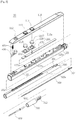
- FIG. 1 is a view schematically showing an electrosurgical device having an easily adjustable length according to an embodiment of the present invention.
- an electrosurgical device 50 having an easily adjustable length which is used for an operator such as a doctor to incise or coagulate a portion of a tissue of a human body, includes a body 100, an operation unit 200 (shown in FIG. 2 ), a stretching member 300, a button stopper 400, a contact guide 500 (shown in FIG. 2 ), and a blade 600.
- the direction close to a tissue of a human body is defined as a forward direction and the opposite direction is defined as a backward direction when a user incises or coagulates a tissue of a human body, using the blade 600 with the body 100 in his/her hand.
- FIGS. 2 and 3 Detailed configurations of the components are described hereafter with reference to FIGS. 2 and 3 .
- FIG. 2 is an exploded view showing the electrosurgical device having an easily adjustable length according to an embodiment of the present invention.
- FIG. 3 is a cross-sectional view schematically showing the electrosurgical device having an easily adjustable length according to an embodiment of the present invention.
- the body 100 which is a part that a user holds with his/her hand, is elongated in a longitudinal direction and has a space longitudinally defined therein.
- the body 100 may include a lower body 120 longitudinally elongated and an upper body 110 disposed over the lower body 120.
- the upper body 110 and the lower body 120 may be integrated in one unit.
- the space may have a first receiving portion 110a disposed between a top plate 122 disposed on the top of the lower body 120 and the upper body 110 and a second receiving portion 120a disposed under the top plate 122, that is, in the lower body 120.
- the second receiving portion 120a may be open at the front and rear longitudinal ends.
- the operation unit 200 includes operation members 210, a substrate 220, and a contact member 230.
- the operation member 210 for example, which may be one or more buttons or touch panels, are disposed at a predetermined distance backward from the front of the first receiving portion 110a, and have tops that are open through the top of the first receiving portion 110a.
- Operation holes 111 are formed through the upper body 110 at positions corresponding to the operation members 210 and the operation members 210 are exposed through the operation holes 111.
- the substrate 220 is, for example, a PCB (Printed Circuit Board), is disposed in the first receiving portion 110a to face the operation members 210, and is electrically connected with the operation members 210.
- PCB Print Circuit Board
- the substrate adjusts the amount of high-frequency energy applied from the outside when the operation members 210 are operated, and then transmits the high-frequency energy to the blade 600 to be described below.
- the contact member 230 is made of a conductive material, is elongated backward along the top of the second receiving portion 120a of the lower body 120, and has contact projections 232 to be electrically connected with the substrate 220 through the top plate 122 disposed on the second receiving portion 120a.
- Projection holes 122a are formed through the top plate 122 at positions corresponding to the contact projections 232, so the contact projections 232 are electrically connected with the substrate 220 through the projection holes 122a.
- the stretching member 300 is inserted in the second receiving portion 120a and positioned under the contact member 230 disposed on the second receiving portion 120a.
- the stretching member 300 is configured to be able to longitudinally move in the second receiving portion 120a, and has a suction passage 300a longitudinally formed therein and a plurality of locking steps 302 longitudinally formed from the front portion to the rear portion on the top facing the first receiving portion 110a.
- a coupling guide 310 may be coupled to the front of the suction passage 300a of the stretching member 300 and the rear of the suction passage 300a of the stretching member 300 may be positioned inward further than the rear of the second receiving portion 120a.
- the coupling guide 310 is formed in a cylindrical shape and has a coupling portion 312 of which both ends are open, at the rear thereof.
- a suction unit (not shown) having a smoke evacuator is connected to the rear of the second receiving portion 120a to suction air so that smoke that is dispersed around the blade 600 when a user incises or coagulates a portion of a tissue of the body of a patient, using the blade 600, is easily suctioned into the suction passage 300a and the second receiving portion 120a.
- the button stopper 400 and the elastic member 450 restrict movement of the stretching member 300 and are described with reference to FIG. 4 .
- the contact guide 500 is made of a conductive material, is elongated in the longitudinal direction of the suction passage 300a, and has a blade coupling portion 502 at the longitudinal front end and a contact terminal 504 bending toward the contact member through the suction passage 300a, at the longitudinal rear end thereof.
- the blade coupling portion 502 is inserted and fixed in the rear portion of the coupling portion 312 of the coupling guide 310.
- the blade 600 is longitudinally elongated with an end inserted in the front portion of the coupling portion 312 of the coupling guide 310 and electrically connected with the blade coupling portion 502 of the contact guide 500 and the other end extending into the front portion of the suction passage 300a.
- High-frequency energy applied to the substrate 200 from the outside is transmitted to the blade 600 through the contact member 230 and the contact guide 500, so a portion of the tissue of the patient's body is incised or coagulated by the high-frequency energy.
- FIG. 4 is view showing the button stopper and the elastic member combined with a body of the electrosurgical device having an easily adjustable length according to an embodiment of the present invention.
- FIG. 5 is a cross-sectional view showing the button stopper and the elastic member combined with the body of the electrosurgical device having an easily adjustable length according to an embodiment of the present invention.
- the button stopper 400 which is rotated on the body 100 to or not to be locked to the locking steps 302, has a rotation guide 402 rotatably disposed on the top plate 122 of the lower body 120, a locking portion 404 extending from the longitudinal front of the rotation guide 402 to be locked to the locking steps 302, and a button portion 406 extending upward to be exposed from the longitudinal rear of the rotation guide 402.
- a first guide 405 protrudes upward from the locking portion 404 and a second guide 114 protrudes from the inner side of the upper body 110 to face the first guide 405.
- the second guide 114 is formed in a ring shape.
- the elastic member 450 to be described below is fitted between the first guide 405 and the second guide 114.
- the elastic member 450 which presses upward the button portion 406 by applying downward to the locking portion 404 of the button stopper 400, may include a plate spring, a coil spring, and a rubber member.
- the elastic member 450 is fitted between the first guide 405 and the second guide 114, whereby it is supported by the first guide 405 and pressed downward the locking portion 404 connected with the second guide 114.
- a button hole 112 is formed at the position corresponding to the button portion 406 of the upper body 110, so the button portion 406 is exposed to the outside through the button hole 112.
- a button guide 124 is formed on the top plate 122 of the lower body 120 at a position corresponding to the button stopper 400.
- the button guide 124 has a coupling pivot 124a in which the rotation guide 402 is rotatably inserted, a locking guide 124b formed through the top plate at the front of the coupling pivot 124a such that the locking portion 404 is inserted in the second receiving portion 120a of the lower body 120, and a downward guide 124c formed through the top plate at the rear of the coupling pivot 124a such that the rear of the rotation guide 402 is inserted in the second receiving portion 120a.
- the locking portion 404 When the button 406 is pressed down, the locking portion 404 is lifted not to be locked to the locking steps 302. Further, when the button portion 406 is pressed up, the locking portion 404 is moved down and locked to the locking steps 302. When the locking portion 404 of the button stopper 400 is locked to the locking steps 302, the stretching member 300 is locked and restricted in movement.
- the stretching member 300 is unlocked. Further, as the stretching member 300 is unlocked, the stretching member 300 is moved in the lower body 120, so the entire length is adjusted. Further, when the entire length is adjusted, the elastic member 450 presses up the button portion 406 and the stretching member 300 is naturally locked. Accordingly, an operator does not need to specifically lock the stretching member 300 in complicated operation environments.
- FIG. 6 is a view showing another example of the button stopper and the elastic member combined with the body of the electrosurgical device having an easily adjustable length according to an embodiment of the present invention.
- an elastic member 460 may be disposed under the button portion 406.
- the elastic member 460 is supported on the top plate 122 disposed under the button portion 406 and presses up the button portion 406.
- the elastic member 460 may include a plate spring, a coil spring, or a rubber member.
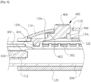
- FIG. 7 is a view showing the contact member and the contact guide that are in contact with each other in the electrosurgical device having an easily adjustable length according to an embodiment of the present invention.
- a cut guide 304 is elongated toward the front of the stretching member 300 at the rear portion of the stretching member 300.
- the contact member 230 is elongated to cover the cut guide 304.
- the contact terminal 504 of the contact guide 500 is bent toward the cut guide 304 to be in contact with the contact member 230 through the cut guide 304.
- the contact terminal 504 of the contact guide 500 connected with the stretching member 300 is also moved forward or backward, in which the contact terminal 504 is moved forward or backward in contact with the contact member 230 disposed on the stretching member 300.
- FIG. 8 is a view showing forward movement of the stretching member in the electrosurgical device having an easily adjustable length according to an embodiment of the present invention.
- the electrosurgical device 50 having an easily adjustable length
- the button portion 406 of the button stopper 400 is pressed down
- the locking portion 404 of the button stopper 400 is lifted and the stretching member 300 is unlocked.
- the stretching member 300 is moved forward or backward in the second receiving portion 120a, so the entire length is easily adjusted.
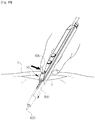
- FIGS. 9 and 10 are views schematically showing a difference in insertion depth in a skin tissue, depending on the position of the stretching unit in the electrosurgical device having an easily adjustable length according to an embodiment of the present invention.
- an operator holds the body 100 and inserts the blade 600 through incised skin S.
- the stretching member 300 since the stretching member 300 has been moved backward, the lengths of the body 100 and the blade 600 is too small, so the blade 600 cannot be pushed deep into the incised skin S.
- the operator holding the body 100 moves the stretching member 300 forward in the second receiving portion 120a by pressing down the button portion 406 of the button stopper 400.
- the operator holds with his/her hand and moves forward the stretching member 300.
- the blade 600 is moved forward together with the stretching member 300.
- the locking portion 404 of the button stopper 400 is locked to the locking steps 302 of the stretching member 300, whereby the stretching member 300 is naturally locked.
- the stretching member 300 in one-touch button type that pressing down the button portion 406 once, the stretching member 300 combined with the blade 600 can be easily moved in the body 100, and accordingly, the entire length can be easily adjusted. Accordingly, an operator can easily insert the blade 600 through incised skin of a patient.
Landscapes
- Health & Medical Sciences (AREA)
- Surgery (AREA)
- Engineering & Computer Science (AREA)
- Life Sciences & Earth Sciences (AREA)
- Heart & Thoracic Surgery (AREA)
- Animal Behavior & Ethology (AREA)
- Nuclear Medicine, Radiotherapy & Molecular Imaging (AREA)
- Otolaryngology (AREA)
- Veterinary Medicine (AREA)
- Public Health (AREA)
- Physics & Mathematics (AREA)
- Biomedical Technology (AREA)
- Medical Informatics (AREA)
- Molecular Biology (AREA)
- Plasma & Fusion (AREA)
- General Health & Medical Sciences (AREA)
- Neurosurgery (AREA)
- Neurology (AREA)
- Surgical Instruments (AREA)
Applications Claiming Priority (2)
| Application Number | Priority Date | Filing Date | Title |
|---|---|---|---|
| KR1020150174736A KR101801027B1 (ko) | 2015-11-20 | 2015-12-09 | 길이 조절이 용이한 전기 수술 장치 |
| PCT/KR2016/000543 WO2017099291A1 (fr) | 2015-12-09 | 2016-01-19 | Dispositif électrochirurgical ayant une longueur facile à régler |
Publications (3)
| Publication Number | Publication Date |
|---|---|
| EP3388009A1 true EP3388009A1 (fr) | 2018-10-17 |
| EP3388009A4 EP3388009A4 (fr) | 2019-07-31 |
| EP3388009B1 EP3388009B1 (fr) | 2025-04-23 |
Family
ID=59013419
Family Applications (1)
| Application Number | Title | Priority Date | Filing Date |
|---|---|---|---|
| EP16873157.8A Active EP3388009B1 (fr) | 2015-12-09 | 2016-01-19 | Dispositif électrochirurgical ayant une longueur facile à régler |
Country Status (7)
| Country | Link |
|---|---|
| US (1) | US11419669B2 (fr) |
| EP (1) | EP3388009B1 (fr) |
| JP (1) | JP6609876B2 (fr) |
| KR (1) | KR101801027B1 (fr) |
| CN (1) | CN108366821B (fr) |
| ES (1) | ES3024509T3 (fr) |
| WO (1) | WO2017099291A1 (fr) |
Families Citing this family (17)
| Publication number | Priority date | Publication date | Assignee | Title |
|---|---|---|---|---|
| US11992261B2 (en) * | 2017-05-16 | 2024-05-28 | Megadyne Medical Products, Inc. | Locking mechanism and sliding conductor for extendable shaft |
| KR102070891B1 (ko) * | 2018-03-08 | 2020-01-29 | 재단법인 대구경북과학기술원 | 미세 수술도구 |
| KR102112244B1 (ko) * | 2018-03-21 | 2020-05-19 | (주)메덴 | 수술용 블레이드 |
| US11399883B2 (en) | 2018-08-20 | 2022-08-02 | Volta Innovations, S. De R.L. De C.V. | Cauterizing device and system |
| US11432866B2 (en) * | 2019-02-04 | 2022-09-06 | Ik Ro Park | Electrosurgery smoke suction apparatus |
| KR102254266B1 (ko) * | 2019-02-11 | 2021-05-21 | 강호상 | 전기수술용 펜슬 |
| USD905854S1 (en) * | 2019-06-07 | 2020-12-22 | Volta Innovations, S. De R.L. De C.V. | Cauterizing device |
| CN110179534A (zh) * | 2019-06-27 | 2019-08-30 | 安徽邵氏华艾生物医疗电子科技有限公司 | 一种纳米刀消融电极 |
| KR102281144B1 (ko) * | 2019-08-30 | 2021-07-22 | 인제대학교 산학협력단 | 의료용 바이오소재 유닛 및 바이오소재 부착용 어플리케이터 |
| KR102419563B1 (ko) * | 2020-05-06 | 2022-07-11 | 주식회사 바이오유닛 | 고주파 열치료술 바이폴라 전기 소작기 |
| US11911088B2 (en) * | 2020-09-09 | 2024-02-27 | Bio-Protech Inc. | Smoke pencil with swivel device |
| EP4210609A4 (fr) * | 2020-09-14 | 2024-05-22 | Bio-Protech Inc. | Crayon à fumée doté d'un dispositif pivotant |
| KR102577647B1 (ko) * | 2021-10-28 | 2023-09-13 | 주식회사 두리엔 | 전기수술기용 연기 흡입유닛 |
| CN113876415B (zh) * | 2021-11-09 | 2025-12-19 | 默华医疗科技(广州)有限公司 | 一种可调节按钮位置的消融电极及含有其的消融电极系统 |
| CN115590610B (zh) * | 2022-09-28 | 2025-06-27 | 默华医疗科技(湖南)有限公司 | 可伸缩的微创解剖针 |
| AU2024245116A1 (en) * | 2023-03-31 | 2025-11-13 | Covidien Lp | Electrosurgical pencil with smoke evacuation and electrode visualization |
| KR20250064402A (ko) | 2023-11-02 | 2025-05-09 | 현대자동차주식회사 | 양자점 기반의 광센서 소자 및 그것의 제조 방법 |
Family Cites Families (11)
| Publication number | Priority date | Publication date | Assignee | Title |
|---|---|---|---|---|
| US5693044A (en) * | 1992-12-11 | 1997-12-02 | Cosmescu; Ioan | Telescopic surgical device and method therefor |
| US7112199B2 (en) * | 1996-09-20 | 2006-09-26 | Ioan Cosmescu | Multifunctional telescopic monopolar/bipolar surgical device and method therefore |
| US6197024B1 (en) * | 1999-09-22 | 2001-03-06 | Scott Keith Sullivan | Adjustable electrocautery surgical apparatus |
| US7244257B2 (en) * | 2002-11-05 | 2007-07-17 | Sherwood Services Ag | Electrosurgical pencil having a single button variable control |
| DK1902682T3 (en) * | 2003-11-14 | 2017-05-01 | Lina Medical Aps | LENGTH ADJUSTABLE ELECTROSURGICAL PEN WITH SUGGESTIONS |
| US9907621B2 (en) * | 2008-11-14 | 2018-03-06 | Prash Jayaraj | Surgical pencil |
| KR20110002463U (ko) * | 2009-09-03 | 2011-03-09 | 양린산-치 | 흡입 기능을 구비한 전기수술용 전기수술 펜 |
| EP3000426B1 (fr) * | 2011-05-19 | 2017-07-19 | Cimpax ApS | Crayon électrochirurgical avec gaine |
| CA2883231C (fr) * | 2012-08-28 | 2022-12-06 | Instruventional Inc. | Crayon electrochirurgical reglable |
| KR101586813B1 (ko) * | 2013-06-10 | 2016-01-20 | 주식회사 바이오프로테크 | 길이 조절이 용이한 전기 수술 장치 |
| KR101576730B1 (ko) * | 2014-03-31 | 2015-12-10 | 주식회사 리메드 | 전기수술 기기용 핸드피스 및 이를 포함하는 전기수술 기기 |
-
2015
- 2015-12-09 KR KR1020150174736A patent/KR101801027B1/ko active Active
-
2016
- 2016-01-19 ES ES16873157T patent/ES3024509T3/es active Active
- 2016-01-19 CN CN201680071940.7A patent/CN108366821B/zh active Active
- 2016-01-19 WO PCT/KR2016/000543 patent/WO2017099291A1/fr not_active Ceased
- 2016-01-19 JP JP2018550309A patent/JP6609876B2/ja active Active
- 2016-01-19 US US15/755,203 patent/US11419669B2/en active Active
- 2016-01-19 EP EP16873157.8A patent/EP3388009B1/fr active Active
Also Published As
| Publication number | Publication date |
|---|---|
| EP3388009A4 (fr) | 2019-07-31 |
| CN108366821A (zh) | 2018-08-03 |
| JP2019500189A (ja) | 2019-01-10 |
| ES3024509T3 (en) | 2025-06-04 |
| KR101801027B1 (ko) | 2017-11-27 |
| US11419669B2 (en) | 2022-08-23 |
| US20180243026A1 (en) | 2018-08-30 |
| JP6609876B2 (ja) | 2019-11-27 |
| WO2017099291A1 (fr) | 2017-06-15 |
| EP3388009B1 (fr) | 2025-04-23 |
| KR20170059354A (ko) | 2017-05-30 |
| CN108366821B (zh) | 2021-09-17 |
Similar Documents
| Publication | Publication Date | Title |
|---|---|---|
| US11419669B2 (en) | Electrosurgical device having easily adjustable length | |
| CN104994802B (zh) | 组合电外科手术装置 | |
| US20170281260A1 (en) | Multi-mode combination electrosurgical device | |
| WO1995013027A1 (fr) | Instrument de chirurgie bipolaire pour chirurgie peu invasive | |
| ES2987005T3 (es) | Parche epidérmico para un dispositivo de tratamiento que utiliza energía de RF | |
| CN105555219A (zh) | 能够调节的电外科笔状物 | |
| WO2009036265A1 (fr) | Appareil et procédés pour obtenir un échantillon de tissu | |
| KR101620836B1 (ko) | 피부 치료기 | |
| CN108720922B (zh) | 一种回缩式高频针形电刀 | |
| KR101586813B1 (ko) | 길이 조절이 용이한 전기 수술 장치 | |
| EP3730105B1 (fr) | Appareil chirurgical ophtalmique | |
| CA3004865A1 (fr) | Dispositif d'elevateur de volet de peau a profondeur fixe et methode d'utilisation associee | |
| KR102530186B1 (ko) | 전기 수술용 핸드피이스의 작동봉 잠금장치 | |
| KR102728785B1 (ko) | 전기 소작 기능 및 흡입 기능을 동시에 수행 가능한 전기 소작기 | |
| US20250127557A1 (en) | Monopolar handpiece for electrosurgery | |
| KR20200097981A (ko) | 전기수술용 펜슬 | |
| CN218606806U (zh) | 一种动物手术用能量平台 | |
| WO2017161248A1 (fr) | Dispositif d'aide à la mastectomie chirurgicale | |
| CN222237800U (zh) | 高频电刀尖端保护装置及高频电刀 | |
| KR102595178B1 (ko) | 전기 수술 핸드피이스의 케이블 조립체 | |
| US20210322088A1 (en) | Two-part seal plate for vessel sealer and method of manufacturing same | |
| WO2019022308A1 (fr) | Système haute fréquence à micro-aiguille pour traiter l'acné et son procédé de fonctionnement | |
| CN212140572U (zh) | 一种手术剪 | |
| US20210322089A1 (en) | Two-part seal plate for vessel sealer and method of manufacturing same | |
| US20210401620A1 (en) | Ophthalmic marking device and method of using same |
Legal Events
| Date | Code | Title | Description |
|---|---|---|---|
| STAA | Information on the status of an ep patent application or granted ep patent |
Free format text: STATUS: THE INTERNATIONAL PUBLICATION HAS BEEN MADE |
|
| PUAI | Public reference made under article 153(3) epc to a published international application that has entered the european phase |
Free format text: ORIGINAL CODE: 0009012 |
|
| STAA | Information on the status of an ep patent application or granted ep patent |
Free format text: STATUS: REQUEST FOR EXAMINATION WAS MADE |
|
| 17P | Request for examination filed |
Effective date: 20180709 |
|
| AK | Designated contracting states |
Kind code of ref document: A1 Designated state(s): AL AT BE BG CH CY CZ DE DK EE ES FI FR GB GR HR HU IE IS IT LI LT LU LV MC MK MT NL NO PL PT RO RS SE SI SK SM TR |
|
| AX | Request for extension of the european patent |
Extension state: BA ME |
|
| DAV | Request for validation of the european patent (deleted) | ||
| DAX | Request for extension of the european patent (deleted) | ||
| A4 | Supplementary search report drawn up and despatched |
Effective date: 20190701 |
|
| RIC1 | Information provided on ipc code assigned before grant |
Ipc: A61B 17/00 20060101ALI20190625BHEP Ipc: A61B 18/12 20060101AFI20190625BHEP Ipc: A61B 18/14 20060101ALI20190625BHEP Ipc: A61B 18/00 20060101ALI20190625BHEP |
|
| RAP1 | Party data changed (applicant data changed or rights of an application transferred) |
Owner name: BIO-PROTECH INC. |
|
| RIN1 | Information on inventor provided before grant (corrected) |
Inventor name: PARK, IK RO |
|
| GRAP | Despatch of communication of intention to grant a patent |
Free format text: ORIGINAL CODE: EPIDOSNIGR1 |
|
| STAA | Information on the status of an ep patent application or granted ep patent |
Free format text: STATUS: GRANT OF PATENT IS INTENDED |
|
| INTG | Intention to grant announced |
Effective date: 20241120 |
|
| RIN1 | Information on inventor provided before grant (corrected) |
Inventor name: PARK, IK RO |
|
| GRAS | Grant fee paid |
Free format text: ORIGINAL CODE: EPIDOSNIGR3 |
|
| GRAA | (expected) grant |
Free format text: ORIGINAL CODE: 0009210 |
|
| STAA | Information on the status of an ep patent application or granted ep patent |
Free format text: STATUS: THE PATENT HAS BEEN GRANTED |
|
| AK | Designated contracting states |
Kind code of ref document: B1 Designated state(s): AL AT BE BG CH CY CZ DE DK EE ES FI FR GB GR HR HU IE IS IT LI LT LU LV MC MK MT NL NO PL PT RO RS SE SI SK SM TR |
|
| REG | Reference to a national code |
Ref country code: GB Ref legal event code: FG4D |
|
| REG | Reference to a national code |
Ref country code: CH Ref legal event code: EP |
|
| REG | Reference to a national code |
Ref country code: DE Ref legal event code: R096 Ref document number: 602016092022 Country of ref document: DE |
|
| REG | Reference to a national code |
Ref country code: IE Ref legal event code: FG4D |
|
| REG | Reference to a national code |
Ref country code: ES Ref legal event code: FG2A Ref document number: 3024509 Country of ref document: ES Kind code of ref document: T3 Effective date: 20250604 |
|
| REG | Reference to a national code |
Ref country code: NL Ref legal event code: MP Effective date: 20250423 |
|
| PG25 | Lapsed in a contracting state [announced via postgrant information from national office to epo] |
Ref country code: NL Free format text: LAPSE BECAUSE OF FAILURE TO SUBMIT A TRANSLATION OF THE DESCRIPTION OR TO PAY THE FEE WITHIN THE PRESCRIBED TIME-LIMIT Effective date: 20250423 |
|
| REG | Reference to a national code |
Ref country code: AT Ref legal event code: MK05 Ref document number: 1787034 Country of ref document: AT Kind code of ref document: T Effective date: 20250423 |
|
| PG25 | Lapsed in a contracting state [announced via postgrant information from national office to epo] |
Ref country code: PT Free format text: LAPSE BECAUSE OF FAILURE TO SUBMIT A TRANSLATION OF THE DESCRIPTION OR TO PAY THE FEE WITHIN THE PRESCRIBED TIME-LIMIT Effective date: 20250825 Ref country code: FI Free format text: LAPSE BECAUSE OF FAILURE TO SUBMIT A TRANSLATION OF THE DESCRIPTION OR TO PAY THE FEE WITHIN THE PRESCRIBED TIME-LIMIT Effective date: 20250423 |
|
| REG | Reference to a national code |
Ref country code: LT Ref legal event code: MG9D |
|
| PG25 | Lapsed in a contracting state [announced via postgrant information from national office to epo] |
Ref country code: NO Free format text: LAPSE BECAUSE OF FAILURE TO SUBMIT A TRANSLATION OF THE DESCRIPTION OR TO PAY THE FEE WITHIN THE PRESCRIBED TIME-LIMIT Effective date: 20250723 Ref country code: GR Free format text: LAPSE BECAUSE OF FAILURE TO SUBMIT A TRANSLATION OF THE DESCRIPTION OR TO PAY THE FEE WITHIN THE PRESCRIBED TIME-LIMIT Effective date: 20250724 |
|
| PG25 | Lapsed in a contracting state [announced via postgrant information from national office to epo] |
Ref country code: PL Free format text: LAPSE BECAUSE OF FAILURE TO SUBMIT A TRANSLATION OF THE DESCRIPTION OR TO PAY THE FEE WITHIN THE PRESCRIBED TIME-LIMIT Effective date: 20250423 |
|
| PG25 | Lapsed in a contracting state [announced via postgrant information from national office to epo] |
Ref country code: BG Free format text: LAPSE BECAUSE OF FAILURE TO SUBMIT A TRANSLATION OF THE DESCRIPTION OR TO PAY THE FEE WITHIN THE PRESCRIBED TIME-LIMIT Effective date: 20250423 |
|
| PG25 | Lapsed in a contracting state [announced via postgrant information from national office to epo] |
Ref country code: HR Free format text: LAPSE BECAUSE OF FAILURE TO SUBMIT A TRANSLATION OF THE DESCRIPTION OR TO PAY THE FEE WITHIN THE PRESCRIBED TIME-LIMIT Effective date: 20250423 |
|
| PG25 | Lapsed in a contracting state [announced via postgrant information from national office to epo] |
Ref country code: AT Free format text: LAPSE BECAUSE OF FAILURE TO SUBMIT A TRANSLATION OF THE DESCRIPTION OR TO PAY THE FEE WITHIN THE PRESCRIBED TIME-LIMIT Effective date: 20250423 |
|
| PG25 | Lapsed in a contracting state [announced via postgrant information from national office to epo] |
Ref country code: RS Free format text: LAPSE BECAUSE OF FAILURE TO SUBMIT A TRANSLATION OF THE DESCRIPTION OR TO PAY THE FEE WITHIN THE PRESCRIBED TIME-LIMIT Effective date: 20250723 |
|
| PG25 | Lapsed in a contracting state [announced via postgrant information from national office to epo] |
Ref country code: IS Free format text: LAPSE BECAUSE OF FAILURE TO SUBMIT A TRANSLATION OF THE DESCRIPTION OR TO PAY THE FEE WITHIN THE PRESCRIBED TIME-LIMIT Effective date: 20250823 |
|
| PG25 | Lapsed in a contracting state [announced via postgrant information from national office to epo] |
Ref country code: LV Free format text: LAPSE BECAUSE OF FAILURE TO SUBMIT A TRANSLATION OF THE DESCRIPTION OR TO PAY THE FEE WITHIN THE PRESCRIBED TIME-LIMIT Effective date: 20250423 |
|
| PG25 | Lapsed in a contracting state [announced via postgrant information from national office to epo] |
Ref country code: SM Free format text: LAPSE BECAUSE OF FAILURE TO SUBMIT A TRANSLATION OF THE DESCRIPTION OR TO PAY THE FEE WITHIN THE PRESCRIBED TIME-LIMIT Effective date: 20250423 Ref country code: DK Free format text: LAPSE BECAUSE OF FAILURE TO SUBMIT A TRANSLATION OF THE DESCRIPTION OR TO PAY THE FEE WITHIN THE PRESCRIBED TIME-LIMIT Effective date: 20250423 |
|
| PG25 | Lapsed in a contracting state [announced via postgrant information from national office to epo] |
Ref country code: CZ Free format text: LAPSE BECAUSE OF FAILURE TO SUBMIT A TRANSLATION OF THE DESCRIPTION OR TO PAY THE FEE WITHIN THE PRESCRIBED TIME-LIMIT Effective date: 20250423 |
|
| PG25 | Lapsed in a contracting state [announced via postgrant information from national office to epo] |
Ref country code: EE Free format text: LAPSE BECAUSE OF FAILURE TO SUBMIT A TRANSLATION OF THE DESCRIPTION OR TO PAY THE FEE WITHIN THE PRESCRIBED TIME-LIMIT Effective date: 20250423 |
|
| REG | Reference to a national code |
Ref country code: DE Ref legal event code: R097 Ref document number: 602016092022 Country of ref document: DE |
|
| PG25 | Lapsed in a contracting state [announced via postgrant information from national office to epo] |
Ref country code: SK Free format text: LAPSE BECAUSE OF FAILURE TO SUBMIT A TRANSLATION OF THE DESCRIPTION OR TO PAY THE FEE WITHIN THE PRESCRIBED TIME-LIMIT Effective date: 20250423 Ref country code: RO Free format text: LAPSE BECAUSE OF FAILURE TO SUBMIT A TRANSLATION OF THE DESCRIPTION OR TO PAY THE FEE WITHIN THE PRESCRIBED TIME-LIMIT Effective date: 20250423 |
|
| PG25 | Lapsed in a contracting state [announced via postgrant information from national office to epo] |
Ref country code: IT Free format text: LAPSE BECAUSE OF FAILURE TO SUBMIT A TRANSLATION OF THE DESCRIPTION OR TO PAY THE FEE WITHIN THE PRESCRIBED TIME-LIMIT Effective date: 20250423 |
|
| PLBE | No opposition filed within time limit |
Free format text: ORIGINAL CODE: 0009261 |
|
| STAA | Information on the status of an ep patent application or granted ep patent |
Free format text: STATUS: NO OPPOSITION FILED WITHIN TIME LIMIT |
|
| REG | Reference to a national code |
Ref country code: CH Ref legal event code: L10 Free format text: ST27 STATUS EVENT CODE: U-0-0-L10-L00 (AS PROVIDED BY THE NATIONAL OFFICE) Effective date: 20260304 |