EP3388172A1 - Verfahren zur oberflächenbearbeitung eines artikels - Google Patents
Verfahren zur oberflächenbearbeitung eines artikels Download PDFInfo
- Publication number
- EP3388172A1 EP3388172A1 EP18166826.0A EP18166826A EP3388172A1 EP 3388172 A1 EP3388172 A1 EP 3388172A1 EP 18166826 A EP18166826 A EP 18166826A EP 3388172 A1 EP3388172 A1 EP 3388172A1
- Authority
- EP
- European Patent Office
- Prior art keywords
- metal surface
- electrode
- dielectric spacer
- applying
- permeable
- Prior art date
- Legal status (The legal status is an assumption and is not a legal conclusion. Google has not performed a legal analysis and makes no representation as to the accuracy of the status listed.)
- Granted
Links
Images

Classifications
-
- B—PERFORMING OPERATIONS; TRANSPORTING
- B22—CASTING; POWDER METALLURGY
- B22F—WORKING METALLIC POWDER; MANUFACTURE OF ARTICLES FROM METALLIC POWDER; MAKING METALLIC POWDER; APPARATUS OR DEVICES SPECIALLY ADAPTED FOR METALLIC POWDER
- B22F10/00—Additive manufacturing of workpieces or articles from metallic powder
-
- B—PERFORMING OPERATIONS; TRANSPORTING
- B22—CASTING; POWDER METALLURGY
- B22F—WORKING METALLIC POWDER; MANUFACTURE OF ARTICLES FROM METALLIC POWDER; MAKING METALLIC POWDER; APPARATUS OR DEVICES SPECIALLY ADAPTED FOR METALLIC POWDER
- B22F3/00—Manufacture of workpieces or articles from metallic powder characterised by the manner of compacting or sintering; Apparatus specially adapted therefor ; Presses and furnaces
- B22F3/24—After-treatment of workpieces or articles
-
- B—PERFORMING OPERATIONS; TRANSPORTING
- B22—CASTING; POWDER METALLURGY
- B22F—WORKING METALLIC POWDER; MANUFACTURE OF ARTICLES FROM METALLIC POWDER; MAKING METALLIC POWDER; APPARATUS OR DEVICES SPECIALLY ADAPTED FOR METALLIC POWDER
- B22F10/00—Additive manufacturing of workpieces or articles from metallic powder
- B22F10/20—Direct sintering or melting
- B22F10/28—Powder bed fusion, e.g. selective laser melting [SLM] or electron beam melting [EBM]
-
- B—PERFORMING OPERATIONS; TRANSPORTING
- B22—CASTING; POWDER METALLURGY
- B22F—WORKING METALLIC POWDER; MANUFACTURE OF ARTICLES FROM METALLIC POWDER; MAKING METALLIC POWDER; APPARATUS OR DEVICES SPECIALLY ADAPTED FOR METALLIC POWDER
- B22F10/00—Additive manufacturing of workpieces or articles from metallic powder
- B22F10/60—Treatment of workpieces or articles after build-up
-
- B—PERFORMING OPERATIONS; TRANSPORTING
- B23—MACHINE TOOLS; METAL-WORKING NOT OTHERWISE PROVIDED FOR
- B23K—SOLDERING OR UNSOLDERING; WELDING; CLADDING OR PLATING BY SOLDERING OR WELDING; CUTTING BY APPLYING HEAT LOCALLY, e.g. FLAME CUTTING; WORKING BY LASER BEAM
- B23K15/00—Electron-beam welding or cutting
- B23K15/0046—Welding
- B23K15/0086—Welding welding for purposes other than joining, e.g. build-up welding
-
- B—PERFORMING OPERATIONS; TRANSPORTING
- B23—MACHINE TOOLS; METAL-WORKING NOT OTHERWISE PROVIDED FOR
- B23K—SOLDERING OR UNSOLDERING; WELDING; CLADDING OR PLATING BY SOLDERING OR WELDING; CUTTING BY APPLYING HEAT LOCALLY, e.g. FLAME CUTTING; WORKING BY LASER BEAM
- B23K26/00—Working by laser beam, e.g. welding, cutting or boring
- B23K26/0093—Working by laser beam, e.g. welding, cutting or boring combined with mechanical machining or metal-working covered by other subclasses than B23K
-
- B—PERFORMING OPERATIONS; TRANSPORTING
- B23—MACHINE TOOLS; METAL-WORKING NOT OTHERWISE PROVIDED FOR
- B23K—SOLDERING OR UNSOLDERING; WELDING; CLADDING OR PLATING BY SOLDERING OR WELDING; CUTTING BY APPLYING HEAT LOCALLY, e.g. FLAME CUTTING; WORKING BY LASER BEAM
- B23K26/00—Working by laser beam, e.g. welding, cutting or boring
- B23K26/34—Laser welding for purposes other than joining
- B23K26/342—Build-up welding
-
- B—PERFORMING OPERATIONS; TRANSPORTING
- B33—ADDITIVE MANUFACTURING TECHNOLOGY
- B33Y—ADDITIVE MANUFACTURING, i.e. MANUFACTURING OF THREE-DIMENSIONAL [3D] OBJECTS BY ADDITIVE DEPOSITION, ADDITIVE AGGLOMERATION OR ADDITIVE LAYERING, e.g. BY 3D PRINTING, STEREOLITHOGRAPHY OR SELECTIVE LASER SINTERING
- B33Y10/00—Processes of additive manufacturing
-
- B—PERFORMING OPERATIONS; TRANSPORTING
- B33—ADDITIVE MANUFACTURING TECHNOLOGY
- B33Y—ADDITIVE MANUFACTURING, i.e. MANUFACTURING OF THREE-DIMENSIONAL [3D] OBJECTS BY ADDITIVE DEPOSITION, ADDITIVE AGGLOMERATION OR ADDITIVE LAYERING, e.g. BY 3D PRINTING, STEREOLITHOGRAPHY OR SELECTIVE LASER SINTERING
- B33Y40/00—Auxiliary operations or equipment, e.g. for material handling
- B33Y40/20—Post-treatment, e.g. curing, coating or polishing
-
- C—CHEMISTRY; METALLURGY
- C25—ELECTROLYTIC OR ELECTROPHORETIC PROCESSES; APPARATUS THEREFOR
- C25F—PROCESSES FOR THE ELECTROLYTIC REMOVAL OF MATERIALS FROM OBJECTS; APPARATUS THEREFOR
- C25F3/00—Electrolytic etching or polishing
- C25F3/16—Polishing
-
- C—CHEMISTRY; METALLURGY
- C25—ELECTROLYTIC OR ELECTROPHORETIC PROCESSES; APPARATUS THEREFOR
- C25F—PROCESSES FOR THE ELECTROLYTIC REMOVAL OF MATERIALS FROM OBJECTS; APPARATUS THEREFOR
- C25F3/00—Electrolytic etching or polishing
- C25F3/16—Polishing
- C25F3/18—Polishing of light metals
- C25F3/20—Polishing of light metals of aluminium
-
- C—CHEMISTRY; METALLURGY
- C25—ELECTROLYTIC OR ELECTROPHORETIC PROCESSES; APPARATUS THEREFOR
- C25F—PROCESSES FOR THE ELECTROLYTIC REMOVAL OF MATERIALS FROM OBJECTS; APPARATUS THEREFOR
- C25F3/00—Electrolytic etching or polishing
- C25F3/16—Polishing
- C25F3/22—Polishing of heavy metals
-
- C—CHEMISTRY; METALLURGY
- C25—ELECTROLYTIC OR ELECTROPHORETIC PROCESSES; APPARATUS THEREFOR
- C25F—PROCESSES FOR THE ELECTROLYTIC REMOVAL OF MATERIALS FROM OBJECTS; APPARATUS THEREFOR
- C25F3/00—Electrolytic etching or polishing
- C25F3/16—Polishing
- C25F3/22—Polishing of heavy metals
- C25F3/24—Polishing of heavy metals of iron or steel
-
- C—CHEMISTRY; METALLURGY
- C25—ELECTROLYTIC OR ELECTROPHORETIC PROCESSES; APPARATUS THEREFOR
- C25F—PROCESSES FOR THE ELECTROLYTIC REMOVAL OF MATERIALS FROM OBJECTS; APPARATUS THEREFOR
- C25F7/00—Constructional parts, or assemblies thereof, of cells for electrolytic removal of material from objects; Servicing or operating
-
- F—MECHANICAL ENGINEERING; LIGHTING; HEATING; WEAPONS; BLASTING
- F28—HEAT EXCHANGE IN GENERAL
- F28D—HEAT-EXCHANGE APPARATUS, NOT PROVIDED FOR IN ANOTHER SUBCLASS, IN WHICH THE HEAT-EXCHANGE MEDIA DO NOT COME INTO DIRECT CONTACT
- F28D9/00—Heat-exchange apparatus having stationary plate-like or laminated conduit assemblies for both heat-exchange media, the media being in contact with different sides of a conduit wall
- F28D9/0062—Heat-exchange apparatus having stationary plate-like or laminated conduit assemblies for both heat-exchange media, the media being in contact with different sides of a conduit wall the conduits for one heat-exchange medium being formed by spaced plates with inserted elements
-
- F—MECHANICAL ENGINEERING; LIGHTING; HEATING; WEAPONS; BLASTING
- F28—HEAT EXCHANGE IN GENERAL
- F28F—DETAILS OF HEAT-EXCHANGE AND HEAT-TRANSFER APPARATUS, OF GENERAL APPLICATION
- F28F3/00—Plate-like or laminated elements; Assemblies of plate-like or laminated elements
- F28F3/02—Elements or assemblies thereof with means for increasing heat-transfer area, e.g. with fins, with recesses, with corrugations
- F28F3/025—Elements or assemblies thereof with means for increasing heat-transfer area, e.g. with fins, with recesses, with corrugations the means being corrugated, plate-like elements
-
- B—PERFORMING OPERATIONS; TRANSPORTING
- B22—CASTING; POWDER METALLURGY
- B22F—WORKING METALLIC POWDER; MANUFACTURE OF ARTICLES FROM METALLIC POWDER; MAKING METALLIC POWDER; APPARATUS OR DEVICES SPECIALLY ADAPTED FOR METALLIC POWDER
- B22F12/00—Apparatus or devices specially adapted for additive manufacturing; Auxiliary means for additive manufacturing; Combinations of additive manufacturing apparatus or devices with other processing apparatus or devices
- B22F12/40—Radiation means
- B22F12/44—Radiation means characterised by the configuration of the radiation means
-
- B—PERFORMING OPERATIONS; TRANSPORTING
- B22—CASTING; POWDER METALLURGY
- B22F—WORKING METALLIC POWDER; MANUFACTURE OF ARTICLES FROM METALLIC POWDER; MAKING METALLIC POWDER; APPARATUS OR DEVICES SPECIALLY ADAPTED FOR METALLIC POWDER
- B22F3/00—Manufacture of workpieces or articles from metallic powder characterised by the manner of compacting or sintering; Apparatus specially adapted therefor ; Presses and furnaces
- B22F3/24—After-treatment of workpieces or articles
- B22F2003/247—Removing material: carving, cleaning, grinding, hobbing, honing, lapping, polishing, milling, shaving, skiving, turning the surface
-
- B—PERFORMING OPERATIONS; TRANSPORTING
- B22—CASTING; POWDER METALLURGY
- B22F—WORKING METALLIC POWDER; MANUFACTURE OF ARTICLES FROM METALLIC POWDER; MAKING METALLIC POWDER; APPARATUS OR DEVICES SPECIALLY ADAPTED FOR METALLIC POWDER
- B22F2999/00—Aspects linked to processes or compositions used in powder metallurgy
-
- B—PERFORMING OPERATIONS; TRANSPORTING
- B22—CASTING; POWDER METALLURGY
- B22F—WORKING METALLIC POWDER; MANUFACTURE OF ARTICLES FROM METALLIC POWDER; MAKING METALLIC POWDER; APPARATUS OR DEVICES SPECIALLY ADAPTED FOR METALLIC POWDER
- B22F5/00—Manufacture of workpieces or articles from metallic powder characterised by the special shape of the product
- B22F5/10—Manufacture of workpieces or articles from metallic powder characterised by the special shape of the product of articles with cavities or holes, not otherwise provided for in the preceding subgroups
-
- B—PERFORMING OPERATIONS; TRANSPORTING
- B23—MACHINE TOOLS; METAL-WORKING NOT OTHERWISE PROVIDED FOR
- B23K—SOLDERING OR UNSOLDERING; WELDING; CLADDING OR PLATING BY SOLDERING OR WELDING; CUTTING BY APPLYING HEAT LOCALLY, e.g. FLAME CUTTING; WORKING BY LASER BEAM
- B23K2101/00—Articles made by soldering, welding or cutting
- B23K2101/04—Tubular or hollow articles
- B23K2101/14—Heat exchangers
-
- F—MECHANICAL ENGINEERING; LIGHTING; HEATING; WEAPONS; BLASTING
- F28—HEAT EXCHANGE IN GENERAL
- F28F—DETAILS OF HEAT-EXCHANGE AND HEAT-TRANSFER APPARATUS, OF GENERAL APPLICATION
- F28F2255/00—Heat exchanger elements made of materials having special features or resulting from particular manufacturing processes
- F28F2255/18—Heat exchanger elements made of materials having special features or resulting from particular manufacturing processes sintered
-
- F—MECHANICAL ENGINEERING; LIGHTING; HEATING; WEAPONS; BLASTING
- F28—HEAT EXCHANGE IN GENERAL
- F28F—DETAILS OF HEAT-EXCHANGE AND HEAT-TRANSFER APPARATUS, OF GENERAL APPLICATION
- F28F2275/00—Fastening; Joining
- F28F2275/06—Fastening; Joining by welding
- F28F2275/064—Fastening; Joining by welding by induction welding or by using microwaves
-
- Y—GENERAL TAGGING OF NEW TECHNOLOGICAL DEVELOPMENTS; GENERAL TAGGING OF CROSS-SECTIONAL TECHNOLOGIES SPANNING OVER SEVERAL SECTIONS OF THE IPC; TECHNICAL SUBJECTS COVERED BY FORMER USPC CROSS-REFERENCE ART COLLECTIONS [XRACs] AND DIGESTS
- Y02—TECHNOLOGIES OR APPLICATIONS FOR MITIGATION OR ADAPTATION AGAINST CLIMATE CHANGE
- Y02P—CLIMATE CHANGE MITIGATION TECHNOLOGIES IN THE PRODUCTION OR PROCESSING OF GOODS
- Y02P10/00—Technologies related to metal processing
- Y02P10/25—Process efficiency
Definitions
- the described subject matter relates generally to the field of surface finishing, and in particular to the manufacture of heat exchangers and to additive manufacturing of articles with finished surfaces.
- Additive manufacturing refers to a category of manufacturing methods characterized by the fact that the finished part is created by layer-wise construction of a plurality of thin sheets of material. Additive manufacturing may involve applying liquid or powder material to a workstage, then doing some combination of sintering, curing, melting, and/or cutting to create a layer. The process is repeated up to several thousand times to construct the desired finished component or article.
- additive manufacturing Various types include stereo lithography (additively manufacturing objects from layers of a cured photosensitive liquid), electron beam melting (using a powder as feedstock and selectively melting the powder using an electron beam), laser additive manufacturing (using a powder as a feedstock and selectively melting the powder using a laser), and laser object manufacturing (applying thin solid sheets of material over a workstage and using a laser to cut away unwanted portions).
- Scanning is commonly implemented in a raster scanning mode where a plurality of substantially parallel scan lines are used to form the article.
- each layer is often scanned in discrete sections at separate locations along the layer. Seams are thus formed at boundaries between adjacent sections. Scanning section seams, as well as other artifacts of powder fusion or other additive manufacturing processing can contribute to undesirable surface characteristics of components formed by additive manufacturing.
- a method for making an article comprises inputting a digital model of the article into an additive manufacturing apparatus or system comprising an energy source.
- the additive manufacturing apparatus applies energy from the energy source to successively applied incremental quantities of a metal powder, which fuses the powder to form incremental portions of the metal powder according to the digital model to form the article.
- An electrode is disposed over a fused metal surface of the article, and a permeable dielectric spacer is disposed between the fused metal surface and the electrode.
- An electrolyte is infiltrated into the permeable dielectric spacer, and an electrical voltage differential is applied to the electrode and the fused metal surface.
- a method of making a heat exchanger comprises forming a heat exchanger core that includes a plurality of internal fluid flow passages. An electrode is disposed over an internal metal surface of the internal fluid flow passages, and a permeable dielectric spacer is disposed between the internal metal surface and the electrode. An electrolyte is infiltrated into the permeable dielectric spacer, and an electrical voltage differential is applied to the electrode and the internal metal surface. The electrode and the permeable dielectric spacer are then removed from the internal metal surface.
- a method of electropolishing a metal surface comprises disposing an electrode over the metal surface, and a permeable dielectric spacer between the metal surface and the electrode. An electrolyte is infiltrated into the permeable dielectric spacer, and an electrical voltage differential is applied to the electrode and the metal surface to electropolish the metal surface.
- FIG. 1 depicts an example embodiment of an additive manufacturing apparatus and process.
- an example of an additive manufacturing system or apparatus 10 includes energy source 12 that generates an energy beam 14, a first wave guide or other optical guide 16 that is used to guide the energy beam, a second wave guide or optical guide 18, a frame 20, a powder supply 22, a powder processing bed 24, sintered powder material 26, a spreader 28, a powder supply support 30, and a stack support 32.
- energy source 12 that generates an energy beam 14
- a first wave guide or other optical guide 16 that is used to guide the energy beam
- a second wave guide or optical guide 18 a frame 20
- powder supply 22 a powder processing bed 24
- sintered powder material 26 sintered powder material
- spreader 28 a powder supply support 30
- a stack support 32 a stack support
- the type of additive manufacturing process used depends in part on the type of material out of which it is desired to manufacture the component.
- the heat exchanger is made of metal, and a metal-forming additive manufacturing process can be used.
- Such processes can include selective laser sintering (SLS), powder bed laser fusion (PBLF), or direct metal laser sintering (DMLS), in which a layer of metal or metal alloy powder is applied to the workpiece being fabricated and selectively sintered according to the digital model with heat energy from a directed laser beam.
- FIG. 1 merely illustrates one potential additive manufacturing system for creating an additively manufactured article.
- Energy source 12 can be any source capable of creating focused energy.
- energy source 12 can be a laser or an electron beam generator.
- Energy source 12 generates an energy beam 14, which is a beam of focused or focusable energy, such as a laser beam or an electron beam.
- Optical guide 16 such as a mirror is present in some embodiments to deflect radiation in a desired direction.
- a second optical guide 18, such as an optical head is present in some embodiments, and also directs energy in a desired direction.
- optical guide 18 can include a mirror and be attached to an x-y positioning device.
- Frame 20 is used to contain powder material in powder supply 22 and in powder processing bed 24.
- Powder supply 22 and powder processing bed 24 include powder material, such as or powdered metals.
- Powder processing bed 24 further includes fused powder 26.
- Fused powder 26 is powder contained within powder processing bed 24 that has been at least partially sintered or melted.
- Spreader 28 is a spreading device such as an air knife using an inert gas instead of air, which can transfer powder material from powder supply 22 to powder processing bed 24.
- the depiction of spreader 28 in FIG. 1 is of course only schematic in nature, and does not depict specific features such as controllably directed air jet nozzles that could be used to remove metal powder from targeted portions of the assembly including internal cavities such as fluid flow passages in a heat exchanger core.
- Powder supply support 30 and stack support 32 are used to raise and/or lower material thereon during additive manufacturing.
- energy source 12 generates energy beam 14, which is directed by the optical guides 16 and 18 to the powder processing bed 24.
- the energy intensity and scanning rate and pattern of the energy beam 14 can be controlled to produce a desired result in the powder processing bed.
- the result can be partial melting of powder particles resulting in a fused structure after solidification such as a sintered powder metal structure having some degree of porosity derived from the gap spaces between fused powder particles.
- the result from exposure to the energy beam 14 can be complete localized melting and fluidization of the powder particles producing a metal article having a density approaching or equal to that of a cast metal article.
- the energy beam provides homogeneous melting such that an examination of the manufactured articles can detect no particle pattern from the original particles.
- powder supply support 30 is moved to raise the height of powder material supply 22 with respect to frame.
- stack support 32 is moved to lower the height of article with respect to frame 20.
- Spreader 28 transfers a layer of powder from powder supply 22 to powder processing bed 24.
- an object may be constructed layer by layer.
- Components manufactured in this manner may be made as a single, solid component, and are generally stronger if they contain a smaller percentage of oxygen, hydrogen, or carbonaceous gases.
- the quantity of impurities of, for example, oxygen is reduced to less than 50 ppm, or even less than 20 ppm.
- the digital models used in the practice of the disclosure are well-known in the art, and do not require further detailed description here.
- the digital model can be generated from various types of computer aided design (CAD) software, and various formats are known, including but not limited to STL (standard tessellation language) files, AMF (additive manufacturing format) files, PLY files, wavefront (.obj) files, and others that can be open source or proprietary file formats.
- CAD computer aided design
- Manufacture of articles through powder fusion additive manufacturing can result in surfaces that are relatively rough compared to some other more conventional manufacturing techniques. Additionally, one of the beneficial features of additive manufacturing is the capability to fabricate articles with internal features such as internal cavities or passages that are not readily manufacturable by conventional fabricating techniques and that are not readily accessed to smooth, hone, or otherwise finish internal surfaces.
- One non-limiting example embodiment of an application where smooth internal surfaces can be beneficial is for heat exchangers where smooth internal surfaces can promote efficient fluid flow and heat transfer.
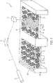
- An example embodiment of a heat exchanger core 100 is schematically depicted in FIG. 2 .
- the heat exchanger assembly 100 can be fabricated using additive manufacturing techniques such as powder bed fusion as described with respect to FIG. 1 , or using any conventional known fabrication technique.
- a portion of a heater core 100 is shown in an isometric view with a cut-away along the front face (end sheet 120) to illustrate the inside of the assembly.
- the heat exchanger core 100 includes a heat absorption side (cold side) fluid flow path 110 through the fin structures 114 and a heat rejection side (hot side) fluid flow path 112 through the fin structures 112.
- the cold and hot side fluid flow paths 110 and 112 are separated by parting sheets 118.
- Parting sheets 118 are also formed from metal alloys and act to support the fin structures 114 and 116.
- End sheets 120 form the outside barriers of primary hot heat exchanger 100.
- Closure bars 122 and 124 form the outside barriers of cold and hot fluid flow paths 110 and 112, respectively.
- Additional structural elements include, but are not limited to core bands that act to support the overall stack of hot and cold fin structures of heat exchanger 100, mounting structures, or fluid flow guide elements.
- the heat exchanger core 100 is typically disposed inside a housing (not shown) that supports and protects the core and provides fluid flow guides (e.g., manifolds, not shown) into and out of the cold and hot side fluid flow paths 110, 112.
- the heat exchanger can be configured for use on an aircraft.
- cold air from a cold air source enters the cold side fluid flow path 110 in the direction indicated by the arrows C.
- Hot air from a hot air source (not shown, e.g., bleed air from a turbocompressor engine or ECS process air on an aircraft) enters the hot side fluid flow path 112 in the direction of arrows H and rejects heat through the fin structures 114, 116 and across the parting sheets 118 to the cold side fluid flow path 110.
- the metal components of heat exchanger 100 may be any metal known in the art of heat exchanger design. In some embodiments, the metal components can be aluminum alloys for low temperature heat exchangers and Ni based alloys for high temperature heat exchangers.
- the powder used in the methods described herein comprises a metal powder.
- Various metals can be used, depending on the material and properties requirements for the application of the finished product.
- Various ferrous steel alloys can be used, including stainless and non-stainless steels, with optional inclusion of various alloying elements such as chromium or nickel for properties such as high-temperature performance.
- Other alloys such as aluminum alloys and titanium can be used as well.
- Metal powders can be formed using a gas atomized process. Examples of particle sizes for the metal powders can range from 5 ⁇ m to 150 ⁇ m.
- the alloy elements can be combined together before forming a powder having a homogeneous composition.
- one or more of the individual alloy elements can have its own powder particles that are mixed with particles of other elements in the alloy mixture, with formation of the actual alloy to occur during the fusion step of the additive manufacturing process.
- the powder is "neat", i.e., it includes only particles of the alloy or alloy elements.
- the powder can include other components such as polymer powder particles. In selective sintering, polymer particles can help to temporarily bind metal powder particles together during processing, to be later removed by pyrolysis caused by the energy source or post-fabrication thermal processing.
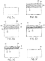
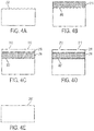
- FIGS. 3 and 4 example embodiments are disclosed by reference to schematic depictions of a metal workpiece (e.g., a heat exchanger exchanger core) or portion(s) thereof.
- a metal workpiece e.g., a heat exchanger exchanger core
- FIGS. 3-4 Each of the embodiments described in FIGS. 3-4 begins with a metal surface 202 shown in FIGS. 3A and 4A .
- the metal surface 202 can be a fused metal surface produced by an additive manufacturing method such as powder bed fusion described with respect to FIG. 1 .
- the metal surface 202 can be an internal metal surface of a fluid flow passage of a heat exchanger core as described in FIG. 2 .
- the metal surface 202 can be an internal surface of any metal object (e.g., a chamber, cavity, conduit or other passageway).
- the metal surface 202 can include a surface dimension (e.g., a channel width or depth) of less than 100 ⁇ m, or less than 50 ⁇ m, or less than 20 ⁇ m. The methods described herein can be used on any other metal surface that is receptive to electropolishing.
- the dielectric particles can comprise any dielectric material such as glass, ceramic, polymers, or composite materials comprising any of these materials.
- Particle sizes can provide a mean particle diameter in a range with a low end of 5 ⁇ m, 10 ⁇ m, or 15 ⁇ m, and a high end of 40 ⁇ m, 45 ⁇ m, , or 50 ⁇ m. These endpoints can be independently combined, and ranges with all possible combinations of the above lower and upper endpoints are hereby explicitly disclosed.
- the removable binder can comprise a wide variety of polymers and coating compositions.
- Coatings can also be removed by heating the coating to a fluid state so that it can be removed with a moving fluid such as air, water or an organic solvent.
- the polymer(s) can be water-soluble (e.g., polyethylene glycol, methoxypolyethylene glycol, polyvinyl alcohol, carboxy methyl cellulose,polyvinyl pyrrolidone, polyacrylic acid, apolyacrylamide, xantham gum, pectins, chitosan derivative, dextran, carrageenan, guar gum, cellulose ethers, or starch based compounds) to facilitate removal with water.
- water-soluble polyalkylene oxides e.g., polyethylene glycol, methoxypolyethylene glycol
- water-soluble polyalkylene oxides e.g., polyethylene glycol, methoxypolyethylene glycol
- the layer 204 can be applied using various coating techniques, including dip coating, spray coating, etc., and can contain various materials and additives known in the art for coatings.
- a layer of a conductive electrode 210 is applied on top of the layer 204.
- the layer of conductive electrode 210 should have sufficient structural integrity to maintain cohesion after the removable binder 208 is removed and the conductive electrode 210 is supported by the remaining dielectric particles 206 ( FIG. 3D ), but can have optional openings such as openings 212 to facilitate removal of the removable binder 208.
- the conductive electrode 210 can be applied using various techniques such as dipping, spraying, injecting, electroplating, electroless plating, deposition of pyrolytic carbon, or chemical vapor deposition,.
- the layer can be also be applied using electrophoresis by applying an electrical charge onto the metal surface 202 so as to deposit a metal or metal precursor onto the layer 204, followed by conversion of any precursor to a metal.
- the electrophoresis technique can be used even if the surface is not readily accessible to application devices such as nozzles.
- a composition comprising metal or other conductor (e.g., conductive carbon) and a polymer binder can be deposited on top of the layer 204 using electrophoresis, spray or any other application technique and fused, cured or coalesced into a cohesive electrode 210.
- the removable binder 208 can be removed by flowing a solvent (e.g., hot water for polyethylene glycol) in and out of the layer 204 through the openings 212 in the conductive electrode 210.
- FIG. 3D schematically shows the conductive electrode over a permeable separator 214 comprising the dielectric particles 206 from the layer 204 with the removable binder 208 removed. As shown in FIG. 3D , some of the dielectric particles 206 may be repositioned in response to removal of the removable binder 208.
- a porous or otherwise permeable electrically non-conductive material is directly applied or formed as a permeable dielectric separator 216 on the metal surface 202, which can form a contiguous porous dielectric material as shown in FIG. 4B .
- materials for the permeable separator 216 include porous ceramics such as silica gel, microporous zeolites, aluminum oxide, silicon carbide or zirconium oxide, which can be deposited or formed on the metal surface 202 by sol gel, chelate, metal-organic decomposition, or Pechini processing.
- Organic polymer foams e.g., expanded polyurethane or polystyrene
- Organic polymers can have a lower dielectric constant than some of the inorganic materials, but this difference can be mitigated by the contribution of void space in the foam.
- the layer of conductive electrode 210 has been applied over the layer of permeable separator 216, using similar techniques as described above with respect to FIG. 3C .
- permeable separator 216 such as a contiguous porous dielectric material can provide structural support for the subsequently applied electrode 210, in which case the electrode 210 need not be self-supporting so that inks and other printing techniques can be used to apply the electrode 210 to the permeable separator 216.
- the permeable separator 214/216 can be infiltrated with a liquid electrolyte, and an electrical voltage differential applied to the electrode 210 and the metal surface 202.
- FIGS. 3E and 4D schematically show the results of the electropolishing with finished metal surface 202'.
- the liquid electrolyte can be an aqueous liquid electrolyte, a non-aqueous organic liquid electrolyte, or an ionic liquid electrolyte.
- Aqueous liquid electrolytes include mixed acid solutions, such as sulfuric and phosphoric acid.
- Non aqueous organic liquids include alcohol, glycol, or organic acid-based solutions with the addition of perchloric acid or an inorganic chloride salt.
- ionic liquids include the choline chloride/urea eutectic.
- the composition and specific properties of the liquid electrolyte can depend on the composition of the metal surface 202 and the electrode 210, the distance between the electrode 210 and the metal surface 210, and the target surface properties of the finished metal surface 202'.
- the thickness of the permeable separator 214/216 can provide a distance between the electrode 210 and the metal surface 210 in a range with a low end of 1 ⁇ m, 10 ⁇ m, or 25 ⁇ m, and a high end of 50 ⁇ m, 100 ⁇ m, or 200 ⁇ m.
- electrolyte resistance can be relatively higher for electropolishing applications compared to other electrolytic processes.
- the electrolyte can have a resistivity in a range with a low end of 1 ohm-cm, 10 ohm-cm, or 100 ohm-cm, and a high end of 100 ohm-cm, 1000 ohm-cm, or 10,000 ohm-cm.
- an electrical circuit through the electrolyte can be completed through electrical contacts (not shown) connected to a power source and to the electrode 210 and the metal surface 202.
- the voltage differential can be in a range with a low end of 2 volts, 5 volts, or 20 volts, and a high end of 25 volts, 50 volts, or 100 volts. These endpoints can be independently combined, and ranges with all possible combinations of the above lower and upper endpoints are hereby explicitly disclosed.
- the current density can be in a range with a low end of 0.1 amp/cm 2 , 1 amp/cm 2 , or 10 amp/cm 2 , and a high end of 10 amp/cm 2 , 100 amp/cm 2 , or 1000 amp/cm 2 .
- These endpoints can be independently combined, and ranges with all possible combinations (excluding impossible combinations where the high end is not greater than the low end) of the above lower and upper endpoints are hereby explicitly disclosed.
- Duration of the electropolishing can be in a range with a low end of 10 seconds, 30 seconds, 60 seconds, or 1200 seconds. These endpoints can be independently combined, and ranges with all possible combinations (excluding impossible combinations where the high end is not greater than the low end) of the above lower and upper endpoints are hereby explicitly disclosed.
- the application of the voltage differential operation can cause evolution of gases such as hydrogen and oxygen.
- removal of such evolved gas can be promoted by flowing the liquid electrolyte or another fluid through the internal cavities or passages.
- removal of evolved gas can be promoted by varying a flow rate of flowing liquid electrolyte through the internal fluid flow passages, or varying the applied electrical voltage or current, or simultaneously varying both the flow rate of flowing liquid electrolyte.
- such variations can include pulsation with periods of no flow rate or electrical voltage interspersed with periods of constant or varying flow rate or electrical voltage.
- the electrode 210 and the permeable dielectric layer 214/216 can be removed to expose the metal surface 202 as shown in FIGS. 3F and 4E .
- a dedicated removal step is not necessarily required, however, as the targeted use of the article could result in removal of the electrode 210 and permeable dielectric layer 214/216 to expose the metal surface 202.
- Electrode 3 can be accomplished by degrading the electrode 210 (e.g., with acid, solvent, thermally, electrolytically, ultrasonically, or a combination thereof, taking into account the material composition and properties of the electrode) and flushing the surface with a fluid such as air, water, or organic solvent to remove the degraded electrode 210 and the dielectric particles 206. Removal of the permeable dielectric layer 216 and electrode 210 in FIG. 4 can be accomplished with similar techniques modified to also provide for degradation of the permeable dielectric layer 216.
- the permeable dielectric spacers and electrodes described herein can be disposed onto a metal surface at intermediate steps during fabrication of an article, or as an end step of the fabrication process. This provides various technical effects allowing for efficient fabrication techniques.
- integration of the permeable dielectric spacer and electrode into a unitary structure with the metal surface allows for articles with complex structures, including but not limited to internal surfaces such as with cavities, channels or conduits, to be electropolished in a single stage.
- Such single-stage electropolishing can be contrasted with conventional electropolishing of internal surfaces such as internal flow passages such as the heater core 100 ( FIG. 2 ), which would require separate stages to be separately applied to each parting sheet-defined course of the heat exchangers.
Landscapes
- Engineering & Computer Science (AREA)
- Chemical & Material Sciences (AREA)
- Materials Engineering (AREA)
- Manufacturing & Machinery (AREA)
- Chemical Kinetics & Catalysis (AREA)
- Electrochemistry (AREA)
- Metallurgy (AREA)
- Organic Chemistry (AREA)
- Mechanical Engineering (AREA)
- Physics & Mathematics (AREA)
- Plasma & Fusion (AREA)
- Optics & Photonics (AREA)
- Thermal Sciences (AREA)
- General Engineering & Computer Science (AREA)
- Powder Metallurgy (AREA)
Applications Claiming Priority (1)
| Application Number | Priority Date | Filing Date | Title |
|---|---|---|---|
| US15/485,048 US10821521B2 (en) | 2017-04-11 | 2017-04-11 | Article surface finishing method |
Publications (2)
| Publication Number | Publication Date |
|---|---|
| EP3388172A1 true EP3388172A1 (de) | 2018-10-17 |
| EP3388172B1 EP3388172B1 (de) | 2020-07-15 |
Family
ID=62067331
Family Applications (1)
| Application Number | Title | Priority Date | Filing Date |
|---|---|---|---|
| EP18166826.0A Active EP3388172B1 (de) | 2017-04-11 | 2018-04-11 | Verfahren zur oberflächenbearbeitung eines artikels |
Country Status (3)
| Country | Link |
|---|---|
| US (1) | US10821521B2 (de) |
| EP (1) | EP3388172B1 (de) |
| CN (1) | CN108687344B (de) |
Cited By (1)
| Publication number | Priority date | Publication date | Assignee | Title |
|---|---|---|---|---|
| EP3640372A1 (de) * | 2018-10-18 | 2020-04-22 | Hirtenberger Engineered Surfaces GmbH | Verfahren zum entfernen von metallischen stützstrukturen an einem additiv gefertigten metallbauteil |
Families Citing this family (8)
| Publication number | Priority date | Publication date | Assignee | Title |
|---|---|---|---|---|
| US20190015923A1 (en) * | 2017-07-11 | 2019-01-17 | United Technologies Corporation | Additively manufactured article including electrically removable supports |
| US11426818B2 (en) | 2018-08-10 | 2022-08-30 | The Research Foundation for the State University | Additive manufacturing processes and additively manufactured products |
| US10739832B2 (en) * | 2018-10-12 | 2020-08-11 | International Business Machines Corporation | Airflow projection for heat transfer device |
| ES2831105B2 (es) * | 2020-02-04 | 2021-10-20 | Steros Gpa Innovative S L | Dispositivo para el electropulido de multiples piezas sin sujecion firme mediante electrolitos solidos |
| US20210262733A1 (en) * | 2020-02-21 | 2021-08-26 | Hamilton Sundstrand Corporation | Heat exchangers and manufacturing methods therefor |
| EP3878579A1 (de) * | 2020-03-09 | 2021-09-15 | Acondicionamiento Tarrasense | Verfahren zur endbearbeitung von edelstahlteilen |
| MX2023006788A (es) * | 2020-12-09 | 2023-06-20 | Drylyte Sl | Proceso de electropulido usando particulas de electrolito solido con fluido no conductor. |
| US20230264265A1 (en) * | 2022-02-18 | 2023-08-24 | Hamilton Sundstrand Corporation | In-situ electrochemical polishing of additively manufactured parts |
Citations (4)
| Publication number | Priority date | Publication date | Assignee | Title |
|---|---|---|---|---|
| US3420759A (en) * | 1966-03-16 | 1969-01-07 | Inoue K | Electromachining using an electrolyte having substantially the same resistivity as the electrode |
| US20140360698A1 (en) * | 2013-06-06 | 2014-12-11 | Honeywell International Inc. | Unitary heat exchangers having integrally-formed compliant heat exchanger tubes and heat exchange systems including the same |
| US20150001093A1 (en) * | 2013-07-01 | 2015-01-01 | General Electric Company | Methods and systems for electrochemical machining of an additively manufactured component |
| WO2016193736A1 (en) * | 2015-06-02 | 2016-12-08 | Datum Alloys Pte. Ltd. | Selective electropolishing method, apparatus and electrolyte |
Family Cites Families (7)
| Publication number | Priority date | Publication date | Assignee | Title |
|---|---|---|---|---|
| CN2361642Y (zh) * | 1999-02-02 | 2000-02-02 | 王国诚 | 电解槽多层可渗透膜隔膜 |
| US7527723B2 (en) * | 2004-01-16 | 2009-05-05 | Ebara Corporation | Electrolytic processing apparatus and electrolytic processing method |
| WO2009126339A2 (en) | 2008-01-14 | 2009-10-15 | Board Of Supervisors Of Louisiana State University And Agricultural And Mechanical College | Metal-based microchannel heat exchangers made by molding replication and assembly |
| JP2009286637A (ja) * | 2008-05-27 | 2009-12-10 | Nissan Motor Co Ltd | 水素生成装置 |
| US20110073464A1 (en) * | 2009-09-28 | 2011-03-31 | General Electric Company | Systems and apparatus relating to electrochemical machining |
| KR101281037B1 (ko) * | 2011-04-06 | 2013-07-09 | 주식회사 엘지화학 | 세퍼레이터 및 이를 구비하는 전기화학소자 |
| CN106374075A (zh) * | 2016-09-26 | 2017-02-01 | 中材科技股份有限公司 | 一种网状多孔复合隔离膜及其制备方法 |
-
2017
- 2017-04-11 US US15/485,048 patent/US10821521B2/en active Active
-
2018
- 2018-04-11 CN CN201810320427.8A patent/CN108687344B/zh active Active
- 2018-04-11 EP EP18166826.0A patent/EP3388172B1/de active Active
Patent Citations (4)
| Publication number | Priority date | Publication date | Assignee | Title |
|---|---|---|---|---|
| US3420759A (en) * | 1966-03-16 | 1969-01-07 | Inoue K | Electromachining using an electrolyte having substantially the same resistivity as the electrode |
| US20140360698A1 (en) * | 2013-06-06 | 2014-12-11 | Honeywell International Inc. | Unitary heat exchangers having integrally-formed compliant heat exchanger tubes and heat exchange systems including the same |
| US20150001093A1 (en) * | 2013-07-01 | 2015-01-01 | General Electric Company | Methods and systems for electrochemical machining of an additively manufactured component |
| WO2016193736A1 (en) * | 2015-06-02 | 2016-12-08 | Datum Alloys Pte. Ltd. | Selective electropolishing method, apparatus and electrolyte |
Cited By (4)
| Publication number | Priority date | Publication date | Assignee | Title |
|---|---|---|---|---|
| EP3640372A1 (de) * | 2018-10-18 | 2020-04-22 | Hirtenberger Engineered Surfaces GmbH | Verfahren zum entfernen von metallischen stützstrukturen an einem additiv gefertigten metallbauteil |
| WO2020079245A1 (de) | 2018-10-18 | 2020-04-23 | Hirtenberger Engineered Surfaces Gmbh | Verfahren zum entfernen von metallischen stützstrukturen an einem additiv gefertigten metallbauteil |
| CN113056577A (zh) * | 2018-10-18 | 2021-06-29 | Rena科技奥地利有限责任公司 | 用于在附加地制得的金属构件上去除金属的支撑结构的方法 |
| JP2022508896A (ja) * | 2018-10-18 | 2022-01-19 | レナ テクノロジーズ オーストリア ゲーエムベーハー | 積層造形された金属部品上の金属製支持構造体を除去するためのプロセス |
Also Published As
| Publication number | Publication date |
|---|---|
| EP3388172B1 (de) | 2020-07-15 |
| CN108687344A (zh) | 2018-10-23 |
| US10821521B2 (en) | 2020-11-03 |
| CN108687344B (zh) | 2022-05-24 |
| US20180290212A1 (en) | 2018-10-11 |
Similar Documents
| Publication | Publication Date | Title |
|---|---|---|
| EP3388172B1 (de) | Verfahren zur oberflächenbearbeitung eines artikels | |
| KR100659008B1 (ko) | 선택적 소결 억제 방법을 이용한 금속 부품 제작 | |
| JP2016014188A (ja) | 繊維強化を用いた付加製造方法及びシステム | |
| CN101780544A (zh) | 一种采用激光成形难熔金属零件的方法 | |
| JP6937587B2 (ja) | 段階的コア部品を含む鋳造方法 | |
| CN113500205B (zh) | 一种双金属材料的3d打印方法 | |
| JP2018154850A (ja) | 粉体材料、積層造形体及び積層造形体の製造方法 | |
| EP4540007A1 (de) | Verfahren zur herstellung einer vorrichtung für filtrations-, chemische oder elektrochemische prozesse mit poröser schicht und trägerschicht und vorrichtung | |
| US10384285B2 (en) | Method of selective laser brazing | |
| CN108290216B (zh) | 3d打印用粉末及3d打印方法 | |
| US10577695B2 (en) | Method for manufacturing discharge surface treatment electrode and method for manufacturing film body | |
| Martin | Exploring additive manufacturing processes for direct 3D printing of copper induction coils | |
| US12447532B2 (en) | Systems and methods for laser additive manufacturing for structured battery electrodes | |
| EP3315227A1 (de) | Verfahren zur herstellung von metallartikeln | |
| JP2011106023A (ja) | 多孔質金属積層体およびその製造方法 | |
| WO2022078630A1 (en) | Method of manufacturing a build plate for use in an additive manufacturing process | |
| JP7355620B2 (ja) | 積層造形物の製造方法 | |
| Heidary et al. | Leveraging Digital Advanced Manufacturing to Enable Polymer Electrolyte Fuel Cells With Ultrahigh Gravimetric Power Density | |
| US12138687B2 (en) | Methods of forming articles including microchannels therein, and related articles | |
| JP2020158839A (ja) | 金属部材の作製方法 | |
| WO2025243274A1 (en) | Additive manufacturing system and method for multi-material, layer-wise deposition, in-situ uv curing, laser debinding, and laser-based melting, fusion, or sintering using multiple jetting heads | |
| WO2025254567A2 (en) | Method of manufacturing of anodes, cathodes of electrolytic capacitors, and blanks for them based on tantalum, niobium, niobium monoxide (niobium oxide ii) by using 3d printing technologies | |
| Dai et al. | Design and verification of a metal 3D printing device based on contact resistance heating | |
| CN117655334A (zh) | 多孔金属体及其制备方法、雾化器发热体及其制备方法 | |
| Stauber et al. | Evaluation of Additive Manufacturing Technologies for Copper Conductors in Electric Drives |
Legal Events
| Date | Code | Title | Description |
|---|---|---|---|
| PUAI | Public reference made under article 153(3) epc to a published international application that has entered the european phase |
Free format text: ORIGINAL CODE: 0009012 |
|
| STAA | Information on the status of an ep patent application or granted ep patent |
Free format text: STATUS: THE APPLICATION HAS BEEN PUBLISHED |
|
| AK | Designated contracting states |
Kind code of ref document: A1 Designated state(s): AL AT BE BG CH CY CZ DE DK EE ES FI FR GB GR HR HU IE IS IT LI LT LU LV MC MK MT NL NO PL PT RO RS SE SI SK SM TR |
|
| AX | Request for extension of the european patent |
Extension state: BA ME |
|
| STAA | Information on the status of an ep patent application or granted ep patent |
Free format text: STATUS: REQUEST FOR EXAMINATION WAS MADE |
|
| 17P | Request for examination filed |
Effective date: 20190417 |
|
| RBV | Designated contracting states (corrected) |
Designated state(s): AL AT BE BG CH CY CZ DE DK EE ES FI FR GB GR HR HU IE IS IT LI LT LU LV MC MK MT NL NO PL PT RO RS SE SI SK SM TR |
|
| RIC1 | Information provided on ipc code assigned before grant |
Ipc: B22F 5/10 20060101ALN20191220BHEP Ipc: C25F 3/20 20060101ALI20191220BHEP Ipc: C25F 3/22 20060101ALI20191220BHEP Ipc: B22F 3/24 20060101AFI20191220BHEP Ipc: C25F 7/00 20060101ALI20191220BHEP Ipc: B22F 3/105 20060101ALN20191220BHEP Ipc: C25F 3/16 20060101ALI20191220BHEP Ipc: B33Y 10/00 20150101ALN20191220BHEP Ipc: B23H 3/00 20060101ALI20191220BHEP Ipc: B33Y 40/00 20150101ALI20191220BHEP |
|
| GRAP | Despatch of communication of intention to grant a patent |
Free format text: ORIGINAL CODE: EPIDOSNIGR1 |
|
| STAA | Information on the status of an ep patent application or granted ep patent |
Free format text: STATUS: GRANT OF PATENT IS INTENDED |
|
| GRAJ | Information related to disapproval of communication of intention to grant by the applicant or resumption of examination proceedings by the epo deleted |
Free format text: ORIGINAL CODE: EPIDOSDIGR1 |
|
| GRAP | Despatch of communication of intention to grant a patent |
Free format text: ORIGINAL CODE: EPIDOSNIGR1 |
|
| INTG | Intention to grant announced |
Effective date: 20200203 |
|
| INTG | Intention to grant announced |
Effective date: 20200214 |
|
| INTG | Intention to grant announced |
Effective date: 20200217 |
|
| RIC1 | Information provided on ipc code assigned before grant |
Ipc: C25F 3/16 20060101ALI20200207BHEP Ipc: C25F 7/00 20060101ALI20200207BHEP Ipc: B33Y 10/00 20150101ALN20200207BHEP Ipc: C25F 3/20 20060101ALI20200207BHEP Ipc: B22F 3/24 20060101AFI20200207BHEP Ipc: B22F 5/10 20060101ALN20200207BHEP Ipc: B33Y 40/00 20200101ALI20200207BHEP Ipc: B23H 3/00 20060101ALI20200207BHEP Ipc: B22F 3/105 20060101ALN20200207BHEP Ipc: C25F 3/22 20060101ALI20200207BHEP |
|
| GRAS | Grant fee paid |
Free format text: ORIGINAL CODE: EPIDOSNIGR3 |
|
| GRAA | (expected) grant |
Free format text: ORIGINAL CODE: 0009210 |
|
| STAA | Information on the status of an ep patent application or granted ep patent |
Free format text: STATUS: THE PATENT HAS BEEN GRANTED |
|
| AK | Designated contracting states |
Kind code of ref document: B1 Designated state(s): AL AT BE BG CH CY CZ DE DK EE ES FI FR GB GR HR HU IE IS IT LI LT LU LV MC MK MT NL NO PL PT RO RS SE SI SK SM TR |
|
| REG | Reference to a national code |
Ref country code: CH Ref legal event code: EP Ref country code: GB Ref legal event code: FG4D |
|
| REG | Reference to a national code |
Ref country code: IE Ref legal event code: FG4D |
|
| REG | Reference to a national code |
Ref country code: DE Ref legal event code: R096 Ref document number: 602018005974 Country of ref document: DE |
|
| REG | Reference to a national code |
Ref country code: AT Ref legal event code: REF Ref document number: 1290438 Country of ref document: AT Kind code of ref document: T Effective date: 20200815 |
|
| REG | Reference to a national code |
Ref country code: LT Ref legal event code: MG4D |
|
| REG | Reference to a national code |
Ref country code: AT Ref legal event code: MK05 Ref document number: 1290438 Country of ref document: AT Kind code of ref document: T Effective date: 20200715 |
|
| REG | Reference to a national code |
Ref country code: NL Ref legal event code: MP Effective date: 20200715 |
|
| PG25 | Lapsed in a contracting state [announced via postgrant information from national office to epo] |
Ref country code: FI Free format text: LAPSE BECAUSE OF FAILURE TO SUBMIT A TRANSLATION OF THE DESCRIPTION OR TO PAY THE FEE WITHIN THE PRESCRIBED TIME-LIMIT Effective date: 20200715 Ref country code: LT Free format text: LAPSE BECAUSE OF FAILURE TO SUBMIT A TRANSLATION OF THE DESCRIPTION OR TO PAY THE FEE WITHIN THE PRESCRIBED TIME-LIMIT Effective date: 20200715 Ref country code: PT Free format text: LAPSE BECAUSE OF FAILURE TO SUBMIT A TRANSLATION OF THE DESCRIPTION OR TO PAY THE FEE WITHIN THE PRESCRIBED TIME-LIMIT Effective date: 20201116 Ref country code: BG Free format text: LAPSE BECAUSE OF FAILURE TO SUBMIT A TRANSLATION OF THE DESCRIPTION OR TO PAY THE FEE WITHIN THE PRESCRIBED TIME-LIMIT Effective date: 20201015 Ref country code: SE Free format text: LAPSE BECAUSE OF FAILURE TO SUBMIT A TRANSLATION OF THE DESCRIPTION OR TO PAY THE FEE WITHIN THE PRESCRIBED TIME-LIMIT Effective date: 20200715 Ref country code: AT Free format text: LAPSE BECAUSE OF FAILURE TO SUBMIT A TRANSLATION OF THE DESCRIPTION OR TO PAY THE FEE WITHIN THE PRESCRIBED TIME-LIMIT Effective date: 20200715 Ref country code: ES Free format text: LAPSE BECAUSE OF FAILURE TO SUBMIT A TRANSLATION OF THE DESCRIPTION OR TO PAY THE FEE WITHIN THE PRESCRIBED TIME-LIMIT Effective date: 20200715 Ref country code: NO Free format text: LAPSE BECAUSE OF FAILURE TO SUBMIT A TRANSLATION OF THE DESCRIPTION OR TO PAY THE FEE WITHIN THE PRESCRIBED TIME-LIMIT Effective date: 20201015 Ref country code: GR Free format text: LAPSE BECAUSE OF FAILURE TO SUBMIT A TRANSLATION OF THE DESCRIPTION OR TO PAY THE FEE WITHIN THE PRESCRIBED TIME-LIMIT Effective date: 20201016 Ref country code: HR Free format text: LAPSE BECAUSE OF FAILURE TO SUBMIT A TRANSLATION OF THE DESCRIPTION OR TO PAY THE FEE WITHIN THE PRESCRIBED TIME-LIMIT Effective date: 20200715 |
|
| PG25 | Lapsed in a contracting state [announced via postgrant information from national office to epo] |
Ref country code: RS Free format text: LAPSE BECAUSE OF FAILURE TO SUBMIT A TRANSLATION OF THE DESCRIPTION OR TO PAY THE FEE WITHIN THE PRESCRIBED TIME-LIMIT Effective date: 20200715 Ref country code: LV Free format text: LAPSE BECAUSE OF FAILURE TO SUBMIT A TRANSLATION OF THE DESCRIPTION OR TO PAY THE FEE WITHIN THE PRESCRIBED TIME-LIMIT Effective date: 20200715 Ref country code: PL Free format text: LAPSE BECAUSE OF FAILURE TO SUBMIT A TRANSLATION OF THE DESCRIPTION OR TO PAY THE FEE WITHIN THE PRESCRIBED TIME-LIMIT Effective date: 20200715 Ref country code: IS Free format text: LAPSE BECAUSE OF FAILURE TO SUBMIT A TRANSLATION OF THE DESCRIPTION OR TO PAY THE FEE WITHIN THE PRESCRIBED TIME-LIMIT Effective date: 20201115 |
|
| PG25 | Lapsed in a contracting state [announced via postgrant information from national office to epo] |
Ref country code: NL Free format text: LAPSE BECAUSE OF FAILURE TO SUBMIT A TRANSLATION OF THE DESCRIPTION OR TO PAY THE FEE WITHIN THE PRESCRIBED TIME-LIMIT Effective date: 20200715 |
|
| REG | Reference to a national code |
Ref country code: DE Ref legal event code: R097 Ref document number: 602018005974 Country of ref document: DE |
|
| PG25 | Lapsed in a contracting state [announced via postgrant information from national office to epo] |
Ref country code: DK Free format text: LAPSE BECAUSE OF FAILURE TO SUBMIT A TRANSLATION OF THE DESCRIPTION OR TO PAY THE FEE WITHIN THE PRESCRIBED TIME-LIMIT Effective date: 20200715 Ref country code: CZ Free format text: LAPSE BECAUSE OF FAILURE TO SUBMIT A TRANSLATION OF THE DESCRIPTION OR TO PAY THE FEE WITHIN THE PRESCRIBED TIME-LIMIT Effective date: 20200715 Ref country code: RO Free format text: LAPSE BECAUSE OF FAILURE TO SUBMIT A TRANSLATION OF THE DESCRIPTION OR TO PAY THE FEE WITHIN THE PRESCRIBED TIME-LIMIT Effective date: 20200715 Ref country code: EE Free format text: LAPSE BECAUSE OF FAILURE TO SUBMIT A TRANSLATION OF THE DESCRIPTION OR TO PAY THE FEE WITHIN THE PRESCRIBED TIME-LIMIT Effective date: 20200715 Ref country code: SM Free format text: LAPSE BECAUSE OF FAILURE TO SUBMIT A TRANSLATION OF THE DESCRIPTION OR TO PAY THE FEE WITHIN THE PRESCRIBED TIME-LIMIT Effective date: 20200715 Ref country code: IT Free format text: LAPSE BECAUSE OF FAILURE TO SUBMIT A TRANSLATION OF THE DESCRIPTION OR TO PAY THE FEE WITHIN THE PRESCRIBED TIME-LIMIT Effective date: 20200715 |
|
| PLBE | No opposition filed within time limit |
Free format text: ORIGINAL CODE: 0009261 |
|
| STAA | Information on the status of an ep patent application or granted ep patent |
Free format text: STATUS: NO OPPOSITION FILED WITHIN TIME LIMIT |
|
| PG25 | Lapsed in a contracting state [announced via postgrant information from national office to epo] |
Ref country code: AL Free format text: LAPSE BECAUSE OF FAILURE TO SUBMIT A TRANSLATION OF THE DESCRIPTION OR TO PAY THE FEE WITHIN THE PRESCRIBED TIME-LIMIT Effective date: 20200715 |
|
| 26N | No opposition filed |
Effective date: 20210416 |
|
| PG25 | Lapsed in a contracting state [announced via postgrant information from national office to epo] |
Ref country code: SK Free format text: LAPSE BECAUSE OF FAILURE TO SUBMIT A TRANSLATION OF THE DESCRIPTION OR TO PAY THE FEE WITHIN THE PRESCRIBED TIME-LIMIT Effective date: 20200715 |
|
| PG25 | Lapsed in a contracting state [announced via postgrant information from national office to epo] |
Ref country code: SI Free format text: LAPSE BECAUSE OF FAILURE TO SUBMIT A TRANSLATION OF THE DESCRIPTION OR TO PAY THE FEE WITHIN THE PRESCRIBED TIME-LIMIT Effective date: 20200715 |
|
| PG25 | Lapsed in a contracting state [announced via postgrant information from national office to epo] |
Ref country code: MC Free format text: LAPSE BECAUSE OF FAILURE TO SUBMIT A TRANSLATION OF THE DESCRIPTION OR TO PAY THE FEE WITHIN THE PRESCRIBED TIME-LIMIT Effective date: 20200715 |
|
| PG25 | Lapsed in a contracting state [announced via postgrant information from national office to epo] |
Ref country code: LU Free format text: LAPSE BECAUSE OF NON-PAYMENT OF DUE FEES Effective date: 20210411 |
|
| REG | Reference to a national code |
Ref country code: BE Ref legal event code: MM Effective date: 20210430 |
|
| PG25 | Lapsed in a contracting state [announced via postgrant information from national office to epo] |
Ref country code: LI Free format text: LAPSE BECAUSE OF NON-PAYMENT OF DUE FEES Effective date: 20210430 Ref country code: CH Free format text: LAPSE BECAUSE OF NON-PAYMENT OF DUE FEES Effective date: 20210430 |
|
| PG25 | Lapsed in a contracting state [announced via postgrant information from national office to epo] |
Ref country code: IE Free format text: LAPSE BECAUSE OF NON-PAYMENT OF DUE FEES Effective date: 20210411 |
|
| PG25 | Lapsed in a contracting state [announced via postgrant information from national office to epo] |
Ref country code: IS Free format text: LAPSE BECAUSE OF FAILURE TO SUBMIT A TRANSLATION OF THE DESCRIPTION OR TO PAY THE FEE WITHIN THE PRESCRIBED TIME-LIMIT Effective date: 20201115 |
|
| PG25 | Lapsed in a contracting state [announced via postgrant information from national office to epo] |
Ref country code: BE Free format text: LAPSE BECAUSE OF NON-PAYMENT OF DUE FEES Effective date: 20210430 |
|
| P01 | Opt-out of the competence of the unified patent court (upc) registered |
Effective date: 20230522 |
|
| PG25 | Lapsed in a contracting state [announced via postgrant information from national office to epo] |
Ref country code: CY Free format text: LAPSE BECAUSE OF FAILURE TO SUBMIT A TRANSLATION OF THE DESCRIPTION OR TO PAY THE FEE WITHIN THE PRESCRIBED TIME-LIMIT Effective date: 20200715 |
|
| PG25 | Lapsed in a contracting state [announced via postgrant information from national office to epo] |
Ref country code: HU Free format text: LAPSE BECAUSE OF FAILURE TO SUBMIT A TRANSLATION OF THE DESCRIPTION OR TO PAY THE FEE WITHIN THE PRESCRIBED TIME-LIMIT; INVALID AB INITIO Effective date: 20180411 |
|
| PG25 | Lapsed in a contracting state [announced via postgrant information from national office to epo] |
Ref country code: MK Free format text: LAPSE BECAUSE OF FAILURE TO SUBMIT A TRANSLATION OF THE DESCRIPTION OR TO PAY THE FEE WITHIN THE PRESCRIBED TIME-LIMIT Effective date: 20200715 |
|
| PG25 | Lapsed in a contracting state [announced via postgrant information from national office to epo] |
Ref country code: MT Free format text: LAPSE BECAUSE OF FAILURE TO SUBMIT A TRANSLATION OF THE DESCRIPTION OR TO PAY THE FEE WITHIN THE PRESCRIBED TIME-LIMIT Effective date: 20200715 |
|
| PGFP | Annual fee paid to national office [announced via postgrant information from national office to epo] |
Ref country code: DE Payment date: 20250319 Year of fee payment: 8 |
|
| PG25 | Lapsed in a contracting state [announced via postgrant information from national office to epo] |
Ref country code: TR Free format text: LAPSE BECAUSE OF FAILURE TO SUBMIT A TRANSLATION OF THE DESCRIPTION OR TO PAY THE FEE WITHIN THE PRESCRIBED TIME-LIMIT Effective date: 20200715 |
|
| PGFP | Annual fee paid to national office [announced via postgrant information from national office to epo] |
Ref country code: GB Payment date: 20260319 Year of fee payment: 9 |
|
| PGFP | Annual fee paid to national office [announced via postgrant information from national office to epo] |
Ref country code: FR Payment date: 20260320 Year of fee payment: 9 |