EP3388256A1 - Pneumatique de véhicule - Google Patents
Pneumatique de véhicule Download PDFInfo
- Publication number
- EP3388256A1 EP3388256A1 EP18155019.5A EP18155019A EP3388256A1 EP 3388256 A1 EP3388256 A1 EP 3388256A1 EP 18155019 A EP18155019 A EP 18155019A EP 3388256 A1 EP3388256 A1 EP 3388256A1
- Authority
- EP
- European Patent Office
- Prior art keywords
- groove
- transverse
- vehicle tire
- width
- pneumatic vehicle
- Prior art date
- Legal status (The legal status is an assumption and is not a legal conclusion. Google has not performed a legal analysis and makes no representation as to the accuracy of the status listed.)
- Granted
Links
Images

Classifications
-
- B—PERFORMING OPERATIONS; TRANSPORTING
- B60—VEHICLES IN GENERAL
- B60C—VEHICLE TYRES; TYRE INFLATION; TYRE CHANGING; CONNECTING VALVES TO INFLATABLE ELASTIC BODIES IN GENERAL; DEVICES OR ARRANGEMENTS RELATED TO TYRES
- B60C11/00—Tyre tread bands; Tread patterns; Anti-skid inserts
- B60C11/03—Tread patterns
- B60C11/0311—Patterns comprising tread lugs arranged parallel or oblique to the axis of rotation
- B60C11/0316—Patterns comprising tread lugs arranged parallel or oblique to the axis of rotation further characterised by the groove cross-section
-
- B—PERFORMING OPERATIONS; TRANSPORTING
- B60—VEHICLES IN GENERAL
- B60C—VEHICLE TYRES; TYRE INFLATION; TYRE CHANGING; CONNECTING VALVES TO INFLATABLE ELASTIC BODIES IN GENERAL; DEVICES OR ARRANGEMENTS RELATED TO TYRES
- B60C11/00—Tyre tread bands; Tread patterns; Anti-skid inserts
- B60C11/03—Tread patterns
- B60C2011/0337—Tread patterns characterised by particular design features of the pattern
- B60C2011/0339—Grooves
- B60C2011/0358—Lateral grooves, i.e. having an angle of 45 to 90 degees to the equatorial plane
- B60C2011/0365—Lateral grooves, i.e. having an angle of 45 to 90 degees to the equatorial plane characterised by width
-
- B—PERFORMING OPERATIONS; TRANSPORTING
- B60—VEHICLES IN GENERAL
- B60C—VEHICLE TYRES; TYRE INFLATION; TYRE CHANGING; CONNECTING VALVES TO INFLATABLE ELASTIC BODIES IN GENERAL; DEVICES OR ARRANGEMENTS RELATED TO TYRES
- B60C11/00—Tyre tread bands; Tread patterns; Anti-skid inserts
- B60C11/03—Tread patterns
- B60C2011/0337—Tread patterns characterised by particular design features of the pattern
- B60C2011/0339—Grooves
- B60C2011/0358—Lateral grooves, i.e. having an angle of 45 to 90 degees to the equatorial plane
- B60C2011/0367—Lateral grooves, i.e. having an angle of 45 to 90 degees to the equatorial plane characterised by depth
Definitions
- the invention relates to a radial pneumatic vehicle tire having a tread with at least one shoulder rib which is provided with transverse grooves extending beyond the lateral edge of the tread, each groove having a groove bottom and groove walls and within the ground contact surface a main portion with grooved edges parallel to each other , wherein the main portion between the groove walls has a width of 1.5 mm to 10.0 mm and wherein at least one groove wall a chamfer edge extending chamfer is set, which in the extension direction of the transverse groove a chamfer main portion and outside the ground contact surface at least a majority its chamfer wider than the chamfer main section running chamfer end portion has.
- Pneumatic vehicle tires with treads of the type mentioned are known in different configurations. It is thus common to provide groove walls of transverse grooves in shoulder-side profile ribs with chamfers running to the groove edges, which are inclined to the radial direction inclined surfaces. Such chamfers are advantageous for the braking properties on dry roads, but at the same time often cause an amplification of the rolling noise.
- the groove edges of the shoulder-side transverse grooves usually extend parallel to each other and beyond the lateral edge of the ground contact patch. In the region of the transverse grooves located outside the ground contacting area, the so-called "off-shoulder" area, the transverse grooves run out, so that the transverse groove cross-section decreases there.
- the transverse groove sections with small transverse groove cross sections which are suddenly located within the ground contact area in such driving situations due to the displacement of the ground contacting surface, lead to an increased risk of aquaplaning when driving on a wet road.
- the invention is therefore based on the object in a pneumatic vehicle tire of the type mentioned to reduce the risk of aquaplaning when cornering on wet roads.
- each transverse groove outside the ground contact surface expires with continuous reduction in depth as a flat depression, each groove having in the circumferential direction at its widest point a width which is greater by at least 40% than the width of the main portion of Transverse groove, wherein each bevel end portion is bounded on the outer surface of the tread rib by an edge portion of its groove edge, which has at least one the transverse groove widening kink, and wherein each bevel end portion runs along the flat recess of the transverse groove.
- the kink in the groove edge of the transverse groove, the chamfer end portion and the flat depression cause an enlargement of the transverse groove cross-section in the shoulder-side outlet region of the transverse grooves.
- water can be discharged particularly effectively beyond the edge of the tread.
- the groove cross-section is increased in the off-shoulder area compared to designs in known tires, the risk of aquaplaning against these tires is significantly reduced.
- the bevel end section and the shallow depression, which broadens the lateral groove to the outside of the tread, ensure good water drainage.
- the depth of the recess at its shoulder-side end decreases to 0.0 mm to 4.0 mm. As a result, water can flow off without turbulence in the off-shoulder area.
- the depth of the recess at its shoulder-side end decreases to 0.5 mm to 1.0 mm.
- the width of the recess at its widest point by at least 50%, in particular by at least 65%, greater than the width of the main portion of the transverse groove. This measure brings about a particularly advantageous enlargement of the transverse groove cross section in the shoulder-side outlet region.
- the bevel end section has a width of 1.5 mm to 3.0 mm, in particular of at least 2.5 mm, at its widest point.
- the chamfer main section has a width of 0.5 mm to 1.5 mm. This measure is advantageous for good braking properties on dry roads.
- the bevel end portion is bounded on the outer surface of the shoulder-side profile rib by an edge portion of the groove edge curved in plan view.
- the curved edge portion in plan view is elongated S-shaped curved.
- the flat recesses of the transverse grooves are elongated in the axial direction and extend to the side wall.
- a chamfer running to the groove edge is also attached to the second groove wall of the transverse groove. Also, this chamfer can assist the drainage of water into the off-shoulder area when it runs along the flat depression of the transverse groove.
- the intended bevel (s), viewed in cross-section, run at a constant angle of 40 ° to 50 °, in particular from 43 ° to 47 °, to the radial direction.
- the transverse grooves in plan view on a spoon-like shape, wherein the recesses each form the spoon bottom.
- the width of the main portion between the groove walls for summer tires is up to 5.0 mm and that for winter tires is 6.0 mm to 8.0 mm.
- Summer tires often have circumferential grooves acting as skin drainage grooves, so that the transverse grooves can be made somewhat narrower while maintaining good drainage capacity. This is advantageous for the braking properties on dry roads and reduces the rolling noise of the summer tire.
- Winter tires often have a tread with a "swept" profile, so are provided with V-shaped mutually extending oblique grooves, which is beneficial for the snow grip. In this case, therefore, there are no circumferential grooves acting as main drainage grooves, so that the drainage ability of water is improved by the deeper shoulder grooves on the shoulder side.
- the width of the main section between the groove walls is preferably up to 10.0, which is advantageous for driving on earthy and muddy ground.
- the rolling noise is of less importance in such tires.
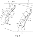
- Fig. 1 and Fig. 2 show a shoulder-side tread rib 1 of a tread of a pneumatic vehicle tire for passenger cars, vans, light trucks or SUVs. Tread inside the tread rib 1 is bounded by a circumferential groove 2. In the second in Fig. 1 and Fig. 2 Not shown tread shoulder can run to a profile rib 1 analogous running rib.
- the tread outside edge of the tread footprint of the tread is in FIG Fig. 1 indicated by a dashed line 1, wherein the ground contact area corresponds to the statically determined footprint load at 70% of the maximum load capacity at an internal pressure of 85% according to ETRTO standard.
- the ground contact surface ends in a known manner in the region of the shoulder-side tread rib 1, so that it has a located within the ground contact surface peripheral portion 1a and located outside the ground contact surface shoulder portion 1b in the "off-shoulder" area.
- the shoulder-side tread rib 1 is provided over its circumferential extent with a multiplicity of transverse grooves 3, 4 extending beyond the edge of the ground contacting surface and therefore extending both in the circumferential section 1a and in the shoulder section 1b, which give the tread rib 1 a block-like structure, alternately following one another in the circumferential direction, each completely within the tread rib 1 run and tread inside at a distance of, for example, 5.0 mm in front of the Tread rib 1 bounding circumferential groove 2 ends.
- the transverse grooves 3, 4 extend in plan view substantially parallel to one another and to the axial direction or under an angle deviating from the axial direction by up to 15 °. At its lowest point, each transverse groove 3, 4 in the radial direction has a depth T 1 (in Fig. 3 for a lateral groove 3) of 3.0 mm to 12.0 mm.
- Each transverse groove 3 has a groove portion 3a extending in sections inside and outside the ground contacting surface and an outlet portion 3b adjoining the raceway outer side end of the groove portion 3a and therefore located in the shoulder portion 1b.
- the groove section 3a extends over at least 50%, in particular over at least 60%, of the extension length of the transverse groove 3 determined in the groove running direction and has a main section 3 "a occupying at least the major part of its extent and located within the ground contact surface, as well as in plan view below an angle to the axial direction extending kinked tread inside end portion 3'a on.
- each transverse groove 3 by a groove bottom 5, two groove walls 6, 6 'and two at the radially outer ends of the groove walls 6, 6' attached chamfers 7, 7 'limited.
- the groove walls 6, 6 ' close in the groove portion 3a to the groove bottom 5 and extend in the embodiment shown in the radial direction, alternatively under an angle of the radial direction preferably by up to 5 °.
- Fig. 2 shows for the groove wall 6, run the groove walls 6, 6 'respectively at the outlet portion 3b.
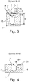
- the main section 3 "a of the transverse groove 3 has a width B 1 between the groove walls 6, 6 '(FIG. Fig.
- the width B 1 is preferably up to 5.0 mm, in treads for winter car tires, which usually have a "swept" profile, 6.0 mm to 8.0 mm. If the tread is intended for an off-road tire, the width B 1 is up to 10.0 mm.
- each discharge section 3b is substantially formed by a shallow depression 3'b which runs off the sidewall of the tire, not shown, with a continuous reduction in its depth.
- the depression 3'b has in the circumferential direction at its widest point a width B 2 determined on the outer surface of the shoulder section 1b, which is 40%, in particular at least 50%, greater than the width B 1 in the main section 3 "a (FIG. Fig. 3 ).
- the depression 3'b has a depth of 0.0 mm to 4.0 mm in the radial direction.
- the recess 3'b can therefore leak to the outer surface of the shoulder portion 1b.
- the depth of the recess 3'b is preferably 0.5 mm to 1.0 mm. If the tread is intended for an off-road (off-road) vehicle, the depth is preferably up to 4.0 mm.
- the inclined edge portion 8'a extends in plan view at an angle ⁇ 'of 20 ° to 45 ° to the transverse direction, that the transverse groove 3 in the outlet section 3b, as already explained widened.
- An edge end section 8'b which extends in a plan view in or in the direction of extension of the transverse groove 3, adjoins the end of the inclined edge section 8'a at the outer side of the strip.
- the chamfer 7 ' extends over the entire extent of the groove wall 6' and to the radial direction at a constant angle ⁇ '(FIG. Fig. 3 ) from 40 ° to 50 °, in particular from 43 ° to 47 °, and has a constant width b F 'within the groove section 3a over most of its extension.
- Fig. 3 from 0.5 mm to 1.5 mm.
- the chamfer 7 'further comprises a beyond the end of the groove wall 6' projecting, extending in the shoulder portion 1b of the tread rib 1 Fasenendabites 7'a, which is bounded on the outer surface of the tread rib 1 by the already mentioned inclined edge portion 8'a and in the outlet section 3b to the recess 3'b and in such a way to the groove bottom 5 of the transverse groove 3 ( Fig. 1 . Fig. 2 ).
- the groove edge 8 delimits the chamfer 7 attached to the groove wall 6.
- the chamfer 7 extends over the entire extent of the groove wall 6 and to the radial direction at an angle ⁇ (FIG. Fig. 3 ) of 40 ° to 50 °, in particular of 43 ° to 47 °, and consists of a over the majority of the groove portion 3a extending bevels main section 7a and a groove section 3a from the groove portion 3a in the outlet section 3b and in the shoulder portion 1b of the tread rib 1 extending 7b together.
- the chamfer main section 7a has a width b F (FIG. Fig.
- the bevel end section 7b adjoins the outer edge of the bevel main section 7a via a kink 9 of the groove edge 8a and extends in the outlet section 3b to the recess 3'b and in particular via a transitional curve to the groove bottom 5. Further, the bevel end section 7b has the majority of its Extension a constant width b F b ( Fig. 4 ) from 1.5 mm to 3.0 mm.
- the bevel end portion 7b runs as Fig. 2 shows, at the mentioned transition rounding to the groove bottom 5.
- Each transverse groove 4 likewise has a groove section 4a, which extends in sections and in sections outside the ground contacting surface, and a downstream section 4b adjoining the shoulder-side end of the groove section 4a and therefore located in the shoulder section 1a.
- the groove section 4a extends over at least 50%, in particular over at least 60%, of the extension length of the transverse groove 4 determined in the groove running direction and has a main section 4 "a occupying at least the major part of its extension and located within the ground contact surface, as well as a top view in the embodiment shown an acute angle to the axial direction extending kinked tread inside end portion 4'a on.
- each transverse groove 4 by a groove bottom 10, two groove walls 11, 11 'and two at the radially outer ends of the groove walls 11, 11' attached chamfers 12, 12 'limited.
- the groove walls 11, 11 'in the groove portion 4a adjoin the groove bottom 10 and extend in the illustrated embodiment in the radial direction, alternatively at one of the radial direction preferably by up to 5 ° different angle.
- the groove wall 11 runs out at the outlet section 4b, the groove wall 11 'extends slightly into the outlet section 4b ( Fig. 1 ).
- the main section 4 "a of the transverse groove 4 also has a width B 1 between the groove walls 11, 11 '(FIG. Fig.
- the preferred width B 1 of the transverse groove 4 for treads for passenger summer tires, for treads for car winter tires and for treads for off-road tires correspond to those already mentioned for the transverse groove 3 widths.
- Each outlet portion 4b is formed substantially by a shallow recess 4'b extending to the tread outside with continuous reduction in its depth, which is wider in the circumferential direction than the groove portion 4a and in the embodiment shown, as the recess 3'b, the width B 2 .
- the groove edge 13 extends over the majority of the extension of the groove portion 4a substantially in the direction of extension of the transverse groove 4 and has a shoulder portion 1b of the tread rib 1 and sections in the groove portion 4a and partially in the outlet portion 4b extending, elongated in plan view S-shaped curved edge portion 13a , which is designed such that the transverse groove 4, as already mentioned widened to the outside of the shoulder portion 1b.
- An edge end section 13b which extends in a plan view in or in the direction of extension of the transverse groove 4, adjoins the outside end of the curved edge section 13a.
- the through the groove edge 13 at the Outside surface of the tread rib 1 limited and scheduled on the groove wall 11 bevel 12 extends over the entire extension of the groove wall 11 and is inclined to the radial direction at an angle of 40 ° to 50 °, in particular from 43 ° to 47 °.
- the chamfer 12 is composed of a chamfer main section 12a running over the majority of the groove section 4a and a chamfer end section 12b extending from the groove section 4a into the outlet section 4b and in the shoulder section 1b of the profile rib 1.
- the chamfer main section 12a like the chamfer main section 7a, has a width of 0.5 mm to 1.5 mm and extends over at least 60%, in particular over at least 70%, of the extension length of the groove section 4a.
- the bevel end portion 12b extends in the outlet portion 4b to the recess 4'b and the groove bottom 10 and is bounded on the outer surface of the tread rib 1 by the curved edge portion 13a.
- the chamfer end section 12b has a width of 1.5 mm to 3.0 mm over the major part of its extension.
- the outlet portions 3b, 4b of circumferentially immediately adjacent transverse grooves 3, 4 in plan view and relative to the axial direction are oriented in opposite directions to each other.
- the bent end portions 3'a, 4'a of all transverse grooves 3, 4 extend in the embodiment shown in plan view substantially parallel to each other.
- Each transverse groove 3, 4 has a spoon-like shape due to its special design in plan view.
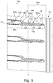
- Fig. 5 shows a plan view of a peripheral portion of a shoulder-side profile rib 14, which is a variant of the tread rib 1 and tread inside is bounded by a circumferential groove 15.
- the tread outside edge of the ground contact patch of the tread is again indicated by a dashed line 1.
- the tread rib 14 has a peripheral portion 14a located within the ground contact patch and a shoulder portion 14b located off the ground contact patch in the off-shoulder region.
- the tread rib 14 is further with in parallel to each other over the edge of the ground contact surface extending in plan view and to the axial direction below a transverse grooves 16 extending at an angle of up to 15 °, which give the tread rib 14 a block-like structure, terminate at a distance in front of the circumferential groove 15, extend to the side wall (in FIG Fig. 5 not shown) of the tire and at their lowest point in the radial direction each have a depth of 3.0 mm to 12.0 mm.
- Each transverse groove 16 has a groove section 16a running in sections and in sections outside the ground contacting surface and an outlet section 16b located in the shoulder section 14b.
- the groove section 16a extends over at least 50%, in particular over at least 60%, of the extension length of the transverse groove 16 determined in the groove running direction and has a main section 16 "a occupying at least the major part of its extension.
- Each transverse groove 16 is bounded by a groove bottom 17, two groove walls 18, 18 'and two bevels 19, 19'.
- the groove walls 18, 18 ' are analogous to the already described groove walls 6, 6', 11, 11 'of the transverse grooves 3, 4 executed.
- the main portion 16 "a of the transverse groove 16 has between the groove walls 18, 18 'also the width B 1 , which is determined at the radially inner end of the lowest in the transverse groove 16 projecting chamfer 19,19' and 1.5 mm to 10
- the preferred width B 1 of the lateral groove 16 for treads for passenger summer tires, for treads for winter car tires and for treads for off-road tires correspond to the widths already mentioned for the transverse groove 3.
- Each spout portion 16b is substantially formed by a recess 16'b elongated in the axial direction at the edge of the shoulder portion 1b of the tread rib 1 while continuously reducing its depth, which is wider in the circumferential direction than the groove portion 16a and circumferentially at its widest point the already mentioned width B 2 , which is greater by 40%, in particular by 50%, than the width B 1 .
- the depression 16 'b has a depth of 0.0 mm to 1.0 mm in the radial direction. The recess 16'b can therefore leak to the outer surface of the shoulder portion 1b.
- An edge end section 20b which extends up to the edge of the shoulder section 14b and which extends in a plan view in the extension direction of the transverse groove 16, adjoins the end of the curved edge section 20a at the outer edge of the runner.
- the chamfer 19 extends over the entire extent of the transverse groove 16 and therefore to the end of the shoulder portion 14b and has a groove section 16a extending in the groove main section 19a and a bevel end portion 19b, which extends in the region of the outlet portion 16b to the recess 16'b and at the Outside surface of the tread rib 14 by the edge end portion 20 b and at least a portion of the curved edge portion 20 a is limited.
- 17 may be formed between the chamfer 19, 19 'and the groove bottom 17 rounding.
- the tread of a pneumatic vehicle tire according to the invention is provided in its one shoulder with a tread rib 1 and in its other shoulder with a tread rib 14.
Landscapes
- Engineering & Computer Science (AREA)
- Mechanical Engineering (AREA)
- Tires In General (AREA)
Applications Claiming Priority (1)
| Application Number | Priority Date | Filing Date | Title |
|---|---|---|---|
| DE102017206383.1A DE102017206383A1 (de) | 2017-04-13 | 2017-04-13 | Fahrzeugluftreifen |
Publications (2)
| Publication Number | Publication Date |
|---|---|
| EP3388256A1 true EP3388256A1 (fr) | 2018-10-17 |
| EP3388256B1 EP3388256B1 (fr) | 2019-11-06 |
Family
ID=61163522
Family Applications (1)
| Application Number | Title | Priority Date | Filing Date |
|---|---|---|---|
| EP18155019.5A Active EP3388256B1 (fr) | 2017-04-13 | 2018-02-05 | Pneumatique de véhicule |
Country Status (2)
| Country | Link |
|---|---|
| EP (1) | EP3388256B1 (fr) |
| DE (1) | DE102017206383A1 (fr) |
Cited By (7)
| Publication number | Priority date | Publication date | Assignee | Title |
|---|---|---|---|---|
| EP3647077A1 (fr) * | 2018-11-01 | 2020-05-06 | Sumitomo Rubber Industries, Ltd. | Pneumatique |
| EP3750723A1 (fr) * | 2019-06-13 | 2020-12-16 | Continental Reifen Deutschland GmbH | Pneumatique de véhicule |
| EP4227115A1 (fr) * | 2022-02-14 | 2023-08-16 | Continental Reifen Deutschland GmbH | Pneumatique pour véhicule |
| CN117062723A (zh) * | 2021-03-26 | 2023-11-14 | 大陆轮胎德国有限公司 | 车辆充气轮胎 |
| CN117580718A (zh) * | 2021-06-29 | 2024-02-20 | 大陆轮胎德国有限公司 | 车辆充气轮胎 |
| DE102022125935B4 (de) | 2021-10-21 | 2025-03-20 | Toyo Tire Corporation | Reifen |
| DE102022127186B4 (de) * | 2021-10-21 | 2025-05-28 | Toyo Tire Corporation | Reifen |
Families Citing this family (3)
| Publication number | Priority date | Publication date | Assignee | Title |
|---|---|---|---|---|
| DE102019200901A1 (de) | 2019-01-24 | 2020-07-30 | Continental Reifen Deutschland Gmbh | Fahrzeugluftreifen |
| DE102019218845A1 (de) | 2019-12-04 | 2021-06-10 | Continental Reifen Deutschland Gmbh | Fahrzeugluftreifen |
| DE102021214496A1 (de) * | 2021-12-16 | 2023-06-22 | Continental Reifen Deutschland Gmbh | Fahrzeugluftreifen |
Citations (4)
| Publication number | Priority date | Publication date | Assignee | Title |
|---|---|---|---|---|
| EP2818333A1 (fr) * | 2012-02-24 | 2014-12-31 | Bridgestone Corporation | Pneumatique |
| DE102015219434A1 (de) * | 2014-10-09 | 2016-04-14 | Toyo Tire & Rubber Co., Ltd. | Pneumatischer Reifen |
| WO2016125814A1 (fr) * | 2015-02-04 | 2016-08-11 | 株式会社ブリヂストン | Pneumatique |
| EP3124290A1 (fr) * | 2015-07-30 | 2017-02-01 | Continental Reifen Deutschland GmbH | Pneumatiques de véhicule |
-
2017
- 2017-04-13 DE DE102017206383.1A patent/DE102017206383A1/de not_active Withdrawn
-
2018
- 2018-02-05 EP EP18155019.5A patent/EP3388256B1/fr active Active
Patent Citations (5)
| Publication number | Priority date | Publication date | Assignee | Title |
|---|---|---|---|---|
| EP2818333A1 (fr) * | 2012-02-24 | 2014-12-31 | Bridgestone Corporation | Pneumatique |
| DE102015219434A1 (de) * | 2014-10-09 | 2016-04-14 | Toyo Tire & Rubber Co., Ltd. | Pneumatischer Reifen |
| WO2016125814A1 (fr) * | 2015-02-04 | 2016-08-11 | 株式会社ブリヂストン | Pneumatique |
| EP3238959A1 (fr) * | 2015-02-04 | 2017-11-01 | Bridgestone Corporation | Pneumatique |
| EP3124290A1 (fr) * | 2015-07-30 | 2017-02-01 | Continental Reifen Deutschland GmbH | Pneumatiques de véhicule |
Cited By (10)
| Publication number | Priority date | Publication date | Assignee | Title |
|---|---|---|---|---|
| EP3647077A1 (fr) * | 2018-11-01 | 2020-05-06 | Sumitomo Rubber Industries, Ltd. | Pneumatique |
| CN111137072A (zh) * | 2018-11-01 | 2020-05-12 | 住友橡胶工业株式会社 | 轮胎 |
| US11364747B2 (en) | 2018-11-01 | 2022-06-21 | Sumitomo Rubber Industries, Ltd. | Tire |
| CN111137072B (zh) * | 2018-11-01 | 2023-03-07 | 住友橡胶工业株式会社 | 轮胎 |
| EP3750723A1 (fr) * | 2019-06-13 | 2020-12-16 | Continental Reifen Deutschland GmbH | Pneumatique de véhicule |
| CN117062723A (zh) * | 2021-03-26 | 2023-11-14 | 大陆轮胎德国有限公司 | 车辆充气轮胎 |
| CN117580718A (zh) * | 2021-06-29 | 2024-02-20 | 大陆轮胎德国有限公司 | 车辆充气轮胎 |
| DE102022125935B4 (de) | 2021-10-21 | 2025-03-20 | Toyo Tire Corporation | Reifen |
| DE102022127186B4 (de) * | 2021-10-21 | 2025-05-28 | Toyo Tire Corporation | Reifen |
| EP4227115A1 (fr) * | 2022-02-14 | 2023-08-16 | Continental Reifen Deutschland GmbH | Pneumatique pour véhicule |
Also Published As
| Publication number | Publication date |
|---|---|
| EP3388256B1 (fr) | 2019-11-06 |
| DE102017206383A1 (de) | 2018-10-18 |
Similar Documents
| Publication | Publication Date | Title |
|---|---|---|
| EP3388256B1 (fr) | Pneumatique de véhicule | |
| EP3589501B1 (fr) | Pneumatique de véhicule | |
| EP3169536B1 (fr) | Pneumatique de véhicule | |
| EP3300926B1 (fr) | Pneumatiques de véhicule | |
| DE102015202614A1 (de) | Fahrzeugluftreifen | |
| DE102019213044A1 (de) | Fahrzeugluftreifen | |
| EP3009275B1 (fr) | Pneumatiques de vehicule | |
| EP3009276B1 (fr) | Pneumatique de vehicule | |
| EP3256335B1 (fr) | Pneumatique de véhicule | |
| DE102019206654A1 (de) | Fahrzeugluftreifen | |
| EP3750723B1 (fr) | Pneumatique de véhicule | |
| EP4058304B1 (fr) | Pneumatique de véhicule | |
| EP3628511B1 (fr) | Pneumatiques de véhicule | |
| EP3450217B1 (fr) | Pneumatique de véhicule | |
| EP3300925B1 (fr) | Pneumatiques de véhicule | |
| EP4244079B1 (fr) | Pneumatique de véhicule | |
| EP3686034B1 (fr) | Pneumatiques de véhicule | |
| EP3418076B1 (fr) | Pneumatique de véhicule | |
| EP3888949A1 (fr) | Pneumatique de véhicule | |
| DE102020205836A1 (de) | Fahrzeugluftreifen | |
| EP4360913B1 (fr) | Bandage pneumatique pour véhicule | |
| EP4140776B1 (fr) | Bandage pneumatique pour véhicule | |
| DE102019213572A1 (de) | Fahrzeugluftreifen | |
| DE102019206679A1 (de) | Fahrzeugluftreifen | |
| EP3750722B1 (fr) | Pneumatique de véhicule |
Legal Events
| Date | Code | Title | Description |
|---|---|---|---|
| PUAI | Public reference made under article 153(3) epc to a published international application that has entered the european phase |
Free format text: ORIGINAL CODE: 0009012 |
|
| STAA | Information on the status of an ep patent application or granted ep patent |
Free format text: STATUS: THE APPLICATION HAS BEEN PUBLISHED |
|
| AK | Designated contracting states |
Kind code of ref document: A1 Designated state(s): AL AT BE BG CH CY CZ DE DK EE ES FI FR GB GR HR HU IE IS IT LI LT LU LV MC MK MT NL NO PL PT RO RS SE SI SK SM TR |
|
| AX | Request for extension of the european patent |
Extension state: BA ME |
|
| STAA | Information on the status of an ep patent application or granted ep patent |
Free format text: STATUS: REQUEST FOR EXAMINATION WAS MADE |
|
| 17P | Request for examination filed |
Effective date: 20190417 |
|
| RBV | Designated contracting states (corrected) |
Designated state(s): AL AT BE BG CH CY CZ DE DK EE ES FI FR GB GR HR HU IE IS IT LI LT LU LV MC MK MT NL NO PL PT RO RS SE SI SK SM TR |
|
| GRAP | Despatch of communication of intention to grant a patent |
Free format text: ORIGINAL CODE: EPIDOSNIGR1 |
|
| STAA | Information on the status of an ep patent application or granted ep patent |
Free format text: STATUS: GRANT OF PATENT IS INTENDED |
|
| INTG | Intention to grant announced |
Effective date: 20190717 |
|
| GRAS | Grant fee paid |
Free format text: ORIGINAL CODE: EPIDOSNIGR3 |
|
| GRAA | (expected) grant |
Free format text: ORIGINAL CODE: 0009210 |
|
| STAA | Information on the status of an ep patent application or granted ep patent |
Free format text: STATUS: THE PATENT HAS BEEN GRANTED |
|
| AK | Designated contracting states |
Kind code of ref document: B1 Designated state(s): AL AT BE BG CH CY CZ DE DK EE ES FI FR GB GR HR HU IE IS IT LI LT LU LV MC MK MT NL NO PL PT RO RS SE SI SK SM TR |
|
| REG | Reference to a national code |
Ref country code: GB Ref legal event code: FG4D Free format text: NOT ENGLISH |
|
| REG | Reference to a national code |
Ref country code: CH Ref legal event code: EP Ref country code: AT Ref legal event code: REF Ref document number: 1198245 Country of ref document: AT Kind code of ref document: T Effective date: 20191115 |
|
| REG | Reference to a national code |
Ref country code: IE Ref legal event code: FG4D Free format text: LANGUAGE OF EP DOCUMENT: GERMAN |
|
| REG | Reference to a national code |
Ref country code: DE Ref legal event code: R096 Ref document number: 502018000336 Country of ref document: DE |
|
| REG | Reference to a national code |
Ref country code: NL Ref legal event code: MP Effective date: 20191106 |
|
| REG | Reference to a national code |
Ref country code: LT Ref legal event code: MG4D |
|
| PG25 | Lapsed in a contracting state [announced via postgrant information from national office to epo] |
Ref country code: SE Free format text: LAPSE BECAUSE OF FAILURE TO SUBMIT A TRANSLATION OF THE DESCRIPTION OR TO PAY THE FEE WITHIN THE PRESCRIBED TIME-LIMIT Effective date: 20191106 Ref country code: LV Free format text: LAPSE BECAUSE OF FAILURE TO SUBMIT A TRANSLATION OF THE DESCRIPTION OR TO PAY THE FEE WITHIN THE PRESCRIBED TIME-LIMIT Effective date: 20191106 Ref country code: NL Free format text: LAPSE BECAUSE OF FAILURE TO SUBMIT A TRANSLATION OF THE DESCRIPTION OR TO PAY THE FEE WITHIN THE PRESCRIBED TIME-LIMIT Effective date: 20191106 Ref country code: BG Free format text: LAPSE BECAUSE OF FAILURE TO SUBMIT A TRANSLATION OF THE DESCRIPTION OR TO PAY THE FEE WITHIN THE PRESCRIBED TIME-LIMIT Effective date: 20200206 Ref country code: FI Free format text: LAPSE BECAUSE OF FAILURE TO SUBMIT A TRANSLATION OF THE DESCRIPTION OR TO PAY THE FEE WITHIN THE PRESCRIBED TIME-LIMIT Effective date: 20191106 Ref country code: NO Free format text: LAPSE BECAUSE OF FAILURE TO SUBMIT A TRANSLATION OF THE DESCRIPTION OR TO PAY THE FEE WITHIN THE PRESCRIBED TIME-LIMIT Effective date: 20200206 Ref country code: GR Free format text: LAPSE BECAUSE OF FAILURE TO SUBMIT A TRANSLATION OF THE DESCRIPTION OR TO PAY THE FEE WITHIN THE PRESCRIBED TIME-LIMIT Effective date: 20200207 Ref country code: PT Free format text: LAPSE BECAUSE OF FAILURE TO SUBMIT A TRANSLATION OF THE DESCRIPTION OR TO PAY THE FEE WITHIN THE PRESCRIBED TIME-LIMIT Effective date: 20200306 Ref country code: LT Free format text: LAPSE BECAUSE OF FAILURE TO SUBMIT A TRANSLATION OF THE DESCRIPTION OR TO PAY THE FEE WITHIN THE PRESCRIBED TIME-LIMIT Effective date: 20191106 Ref country code: PL Free format text: LAPSE BECAUSE OF FAILURE TO SUBMIT A TRANSLATION OF THE DESCRIPTION OR TO PAY THE FEE WITHIN THE PRESCRIBED TIME-LIMIT Effective date: 20191106 |
|
| PG25 | Lapsed in a contracting state [announced via postgrant information from national office to epo] |
Ref country code: HR Free format text: LAPSE BECAUSE OF FAILURE TO SUBMIT A TRANSLATION OF THE DESCRIPTION OR TO PAY THE FEE WITHIN THE PRESCRIBED TIME-LIMIT Effective date: 20191106 Ref country code: RS Free format text: LAPSE BECAUSE OF FAILURE TO SUBMIT A TRANSLATION OF THE DESCRIPTION OR TO PAY THE FEE WITHIN THE PRESCRIBED TIME-LIMIT Effective date: 20191106 Ref country code: IS Free format text: LAPSE BECAUSE OF FAILURE TO SUBMIT A TRANSLATION OF THE DESCRIPTION OR TO PAY THE FEE WITHIN THE PRESCRIBED TIME-LIMIT Effective date: 20200306 |
|
| PG25 | Lapsed in a contracting state [announced via postgrant information from national office to epo] |
Ref country code: AL Free format text: LAPSE BECAUSE OF FAILURE TO SUBMIT A TRANSLATION OF THE DESCRIPTION OR TO PAY THE FEE WITHIN THE PRESCRIBED TIME-LIMIT Effective date: 20191106 |
|
| PG25 | Lapsed in a contracting state [announced via postgrant information from national office to epo] |
Ref country code: CZ Free format text: LAPSE BECAUSE OF FAILURE TO SUBMIT A TRANSLATION OF THE DESCRIPTION OR TO PAY THE FEE WITHIN THE PRESCRIBED TIME-LIMIT Effective date: 20191106 Ref country code: RO Free format text: LAPSE BECAUSE OF FAILURE TO SUBMIT A TRANSLATION OF THE DESCRIPTION OR TO PAY THE FEE WITHIN THE PRESCRIBED TIME-LIMIT Effective date: 20191106 Ref country code: ES Free format text: LAPSE BECAUSE OF FAILURE TO SUBMIT A TRANSLATION OF THE DESCRIPTION OR TO PAY THE FEE WITHIN THE PRESCRIBED TIME-LIMIT Effective date: 20191106 Ref country code: DK Free format text: LAPSE BECAUSE OF FAILURE TO SUBMIT A TRANSLATION OF THE DESCRIPTION OR TO PAY THE FEE WITHIN THE PRESCRIBED TIME-LIMIT Effective date: 20191106 Ref country code: EE Free format text: LAPSE BECAUSE OF FAILURE TO SUBMIT A TRANSLATION OF THE DESCRIPTION OR TO PAY THE FEE WITHIN THE PRESCRIBED TIME-LIMIT Effective date: 20191106 |
|
| REG | Reference to a national code |
Ref country code: DE Ref legal event code: R097 Ref document number: 502018000336 Country of ref document: DE |
|
| PG25 | Lapsed in a contracting state [announced via postgrant information from national office to epo] |
Ref country code: SK Free format text: LAPSE BECAUSE OF FAILURE TO SUBMIT A TRANSLATION OF THE DESCRIPTION OR TO PAY THE FEE WITHIN THE PRESCRIBED TIME-LIMIT Effective date: 20191106 Ref country code: SM Free format text: LAPSE BECAUSE OF FAILURE TO SUBMIT A TRANSLATION OF THE DESCRIPTION OR TO PAY THE FEE WITHIN THE PRESCRIBED TIME-LIMIT Effective date: 20191106 |
|
| PLBE | No opposition filed within time limit |
Free format text: ORIGINAL CODE: 0009261 |
|
| STAA | Information on the status of an ep patent application or granted ep patent |
Free format text: STATUS: NO OPPOSITION FILED WITHIN TIME LIMIT |
|
| 26N | No opposition filed |
Effective date: 20200807 |
|
| REG | Reference to a national code |
Ref country code: BE Ref legal event code: MM Effective date: 20200229 |
|
| PG25 | Lapsed in a contracting state [announced via postgrant information from national office to epo] |
Ref country code: LU Free format text: LAPSE BECAUSE OF NON-PAYMENT OF DUE FEES Effective date: 20200205 Ref country code: MC Free format text: LAPSE BECAUSE OF FAILURE TO SUBMIT A TRANSLATION OF THE DESCRIPTION OR TO PAY THE FEE WITHIN THE PRESCRIBED TIME-LIMIT Effective date: 20191106 |
|
| PG25 | Lapsed in a contracting state [announced via postgrant information from national office to epo] |
Ref country code: SI Free format text: LAPSE BECAUSE OF FAILURE TO SUBMIT A TRANSLATION OF THE DESCRIPTION OR TO PAY THE FEE WITHIN THE PRESCRIBED TIME-LIMIT Effective date: 20191106 |
|
| PG25 | Lapsed in a contracting state [announced via postgrant information from national office to epo] |
Ref country code: IE Free format text: LAPSE BECAUSE OF NON-PAYMENT OF DUE FEES Effective date: 20200205 Ref country code: IT Free format text: LAPSE BECAUSE OF FAILURE TO SUBMIT A TRANSLATION OF THE DESCRIPTION OR TO PAY THE FEE WITHIN THE PRESCRIBED TIME-LIMIT Effective date: 20191106 |
|
| PG25 | Lapsed in a contracting state [announced via postgrant information from national office to epo] |
Ref country code: BE Free format text: LAPSE BECAUSE OF NON-PAYMENT OF DUE FEES Effective date: 20200229 |
|
| PG25 | Lapsed in a contracting state [announced via postgrant information from national office to epo] |
Ref country code: CH Free format text: LAPSE BECAUSE OF NON-PAYMENT OF DUE FEES Effective date: 20210228 Ref country code: LI Free format text: LAPSE BECAUSE OF NON-PAYMENT OF DUE FEES Effective date: 20210228 |
|
| PG25 | Lapsed in a contracting state [announced via postgrant information from national office to epo] |
Ref country code: TR Free format text: LAPSE BECAUSE OF FAILURE TO SUBMIT A TRANSLATION OF THE DESCRIPTION OR TO PAY THE FEE WITHIN THE PRESCRIBED TIME-LIMIT Effective date: 20191106 Ref country code: MT Free format text: LAPSE BECAUSE OF FAILURE TO SUBMIT A TRANSLATION OF THE DESCRIPTION OR TO PAY THE FEE WITHIN THE PRESCRIBED TIME-LIMIT Effective date: 20191106 Ref country code: CY Free format text: LAPSE BECAUSE OF FAILURE TO SUBMIT A TRANSLATION OF THE DESCRIPTION OR TO PAY THE FEE WITHIN THE PRESCRIBED TIME-LIMIT Effective date: 20191106 |
|
| PG25 | Lapsed in a contracting state [announced via postgrant information from national office to epo] |
Ref country code: MK Free format text: LAPSE BECAUSE OF FAILURE TO SUBMIT A TRANSLATION OF THE DESCRIPTION OR TO PAY THE FEE WITHIN THE PRESCRIBED TIME-LIMIT Effective date: 20191106 |
|
| GBPC | Gb: european patent ceased through non-payment of renewal fee |
Effective date: 20220205 |
|
| PG25 | Lapsed in a contracting state [announced via postgrant information from national office to epo] |
Ref country code: GB Free format text: LAPSE BECAUSE OF NON-PAYMENT OF DUE FEES Effective date: 20220205 |
|
| REG | Reference to a national code |
Ref country code: DE Ref legal event code: R081 Ref document number: 502018000336 Country of ref document: DE Owner name: CONTINENTAL REIFEN DEUTSCHLAND GMBH, DE Free format text: FORMER OWNER: CONTINENTAL REIFEN DEUTSCHLAND GMBH, 30165 HANNOVER, DE |
|
| REG | Reference to a national code |
Ref country code: AT Ref legal event code: MM01 Ref document number: 1198245 Country of ref document: AT Kind code of ref document: T Effective date: 20230205 |
|
| PG25 | Lapsed in a contracting state [announced via postgrant information from national office to epo] |
Ref country code: AT Free format text: LAPSE BECAUSE OF NON-PAYMENT OF DUE FEES Effective date: 20230205 |
|
| PG25 | Lapsed in a contracting state [announced via postgrant information from national office to epo] |
Ref country code: AT Free format text: LAPSE BECAUSE OF NON-PAYMENT OF DUE FEES Effective date: 20230205 |
|
| PGFP | Annual fee paid to national office [announced via postgrant information from national office to epo] |
Ref country code: DE Payment date: 20260228 Year of fee payment: 9 |
|
| PGFP | Annual fee paid to national office [announced via postgrant information from national office to epo] |
Ref country code: AT Payment date: 20260410 Year of fee payment: 5 |
|
| PGFP | Annual fee paid to national office [announced via postgrant information from national office to epo] |
Ref country code: FR Payment date: 20260218 Year of fee payment: 9 |