EP3388280A1 - Fahrzeugsteuerungssystem umfassend synchronisierte steuerungsschaltungen - Google Patents
Fahrzeugsteuerungssystem umfassend synchronisierte steuerungsschaltungen Download PDFInfo
- Publication number
- EP3388280A1 EP3388280A1 EP18166104.2A EP18166104A EP3388280A1 EP 3388280 A1 EP3388280 A1 EP 3388280A1 EP 18166104 A EP18166104 A EP 18166104A EP 3388280 A1 EP3388280 A1 EP 3388280A1
- Authority
- EP
- European Patent Office
- Prior art keywords
- control
- microcomputer
- reset signal
- circuit
- signal
- Prior art date
- Legal status (The legal status is an assumption and is not a legal conclusion. Google has not performed a legal analysis and makes no representation as to the accuracy of the status listed.)
- Granted
Links
Images


Classifications
-
- B—PERFORMING OPERATIONS; TRANSPORTING
- B60—VEHICLES IN GENERAL
- B60L—PROPULSION OF ELECTRICALLY-PROPELLED VEHICLES; SUPPLYING ELECTRIC POWER FOR AUXILIARY EQUIPMENT OF ELECTRICALLY-PROPELLED VEHICLES; ELECTRODYNAMIC BRAKE SYSTEMS FOR VEHICLES IN GENERAL; MAGNETIC SUSPENSION OR LEVITATION FOR VEHICLES; MONITORING OPERATING VARIABLES OF ELECTRICALLY-PROPELLED VEHICLES; ELECTRIC SAFETY DEVICES FOR ELECTRICALLY-PROPELLED VEHICLES
- B60L15/00—Methods, circuits, or devices for controlling the traction-motor speed of electrically-propelled vehicles
- B60L15/007—Physical arrangements or structures of drive train converters specially adapted for the propulsion motors of electric vehicles
-
- B—PERFORMING OPERATIONS; TRANSPORTING
- B60—VEHICLES IN GENERAL
- B60R—VEHICLES, VEHICLE FITTINGS, OR VEHICLE PARTS, NOT OTHERWISE PROVIDED FOR
- B60R16/00—Electric or fluid circuits specially adapted for vehicles and not otherwise provided for; Arrangement of elements of electric or fluid circuits specially adapted for vehicles and not otherwise provided for
- B60R16/02—Electric or fluid circuits specially adapted for vehicles and not otherwise provided for; Arrangement of elements of electric or fluid circuits specially adapted for vehicles and not otherwise provided for electric constitutive elements
-
- B—PERFORMING OPERATIONS; TRANSPORTING
- B62—LAND VEHICLES FOR TRAVELLING OTHERWISE THAN ON RAILS
- B62D—MOTOR VEHICLES; TRAILERS
- B62D5/00—Power-assisted or power-driven steering
- B62D5/04—Power-assisted or power-driven steering electrical, e.g. using an electric servo-motor connected to, or forming part of, the steering gear
- B62D5/0457—Power-assisted or power-driven steering electrical, e.g. using an electric servo-motor connected to, or forming part of, the steering gear characterised by control features of the drive means as such
-
- B—PERFORMING OPERATIONS; TRANSPORTING
- B60—VEHICLES IN GENERAL
- B60L—PROPULSION OF ELECTRICALLY-PROPELLED VEHICLES; SUPPLYING ELECTRIC POWER FOR AUXILIARY EQUIPMENT OF ELECTRICALLY-PROPELLED VEHICLES; ELECTRODYNAMIC BRAKE SYSTEMS FOR VEHICLES IN GENERAL; MAGNETIC SUSPENSION OR LEVITATION FOR VEHICLES; MONITORING OPERATING VARIABLES OF ELECTRICALLY-PROPELLED VEHICLES; ELECTRIC SAFETY DEVICES FOR ELECTRICALLY-PROPELLED VEHICLES
- B60L15/00—Methods, circuits, or devices for controlling the traction-motor speed of electrically-propelled vehicles
- B60L15/02—Methods, circuits, or devices for controlling the traction-motor speed of electrically-propelled vehicles characterised by the form of the current used in the control circuit
-
- B—PERFORMING OPERATIONS; TRANSPORTING
- B60—VEHICLES IN GENERAL
- B60L—PROPULSION OF ELECTRICALLY-PROPELLED VEHICLES; SUPPLYING ELECTRIC POWER FOR AUXILIARY EQUIPMENT OF ELECTRICALLY-PROPELLED VEHICLES; ELECTRODYNAMIC BRAKE SYSTEMS FOR VEHICLES IN GENERAL; MAGNETIC SUSPENSION OR LEVITATION FOR VEHICLES; MONITORING OPERATING VARIABLES OF ELECTRICALLY-PROPELLED VEHICLES; ELECTRIC SAFETY DEVICES FOR ELECTRICALLY-PROPELLED VEHICLES
- B60L50/00—Electric propulsion with power supplied within the vehicle
- B60L50/50—Electric propulsion with power supplied within the vehicle using propulsion power supplied by batteries or fuel cells
- B60L50/51—Electric propulsion with power supplied within the vehicle using propulsion power supplied by batteries or fuel cells characterised by AC-motors
-
- G—PHYSICS
- G06—COMPUTING OR CALCULATING; COUNTING
- G06F—ELECTRIC DIGITAL DATA PROCESSING
- G06F11/00—Error detection; Error correction; Monitoring
- G06F11/30—Monitoring
- G06F11/3055—Monitoring arrangements for monitoring the status of the computing system or of the computing system component, e.g. monitoring if the computing system is on, off, available, not available
-
- H—ELECTRICITY
- H02—GENERATION; CONVERSION OR DISTRIBUTION OF ELECTRIC POWER
- H02P—CONTROL OR REGULATION OF ELECTRIC MOTORS, ELECTRIC GENERATORS OR DYNAMO-ELECTRIC CONVERTERS; CONTROLLING TRANSFORMERS, REACTORS OR CHOKE COILS
- H02P27/00—Arrangements or methods for the control of AC motors characterised by the kind of supply voltage
-
- B—PERFORMING OPERATIONS; TRANSPORTING
- B60—VEHICLES IN GENERAL
- B60L—PROPULSION OF ELECTRICALLY-PROPELLED VEHICLES; SUPPLYING ELECTRIC POWER FOR AUXILIARY EQUIPMENT OF ELECTRICALLY-PROPELLED VEHICLES; ELECTRODYNAMIC BRAKE SYSTEMS FOR VEHICLES IN GENERAL; MAGNETIC SUSPENSION OR LEVITATION FOR VEHICLES; MONITORING OPERATING VARIABLES OF ELECTRICALLY-PROPELLED VEHICLES; ELECTRIC SAFETY DEVICES FOR ELECTRICALLY-PROPELLED VEHICLES
- B60L2240/00—Control parameters of input or output; Target parameters
- B60L2240/40—Drive Train control parameters
- B60L2240/52—Drive Train control parameters related to converters
- B60L2240/527—Voltage
-
- B—PERFORMING OPERATIONS; TRANSPORTING
- B60—VEHICLES IN GENERAL
- B60L—PROPULSION OF ELECTRICALLY-PROPELLED VEHICLES; SUPPLYING ELECTRIC POWER FOR AUXILIARY EQUIPMENT OF ELECTRICALLY-PROPELLED VEHICLES; ELECTRODYNAMIC BRAKE SYSTEMS FOR VEHICLES IN GENERAL; MAGNETIC SUSPENSION OR LEVITATION FOR VEHICLES; MONITORING OPERATING VARIABLES OF ELECTRICALLY-PROPELLED VEHICLES; ELECTRIC SAFETY DEVICES FOR ELECTRICALLY-PROPELLED VEHICLES
- B60L2260/00—Operating Modes
- B60L2260/40—Control modes
-
- H—ELECTRICITY
- H02—GENERATION; CONVERSION OR DISTRIBUTION OF ELECTRIC POWER
- H02M—APPARATUS FOR CONVERSION BETWEEN AC AND AC, BETWEEN AC AND DC, OR BETWEEN DC AND DC, AND FOR USE WITH MAINS OR SIMILAR POWER SUPPLY SYSTEMS; CONVERSION OF DC OR AC INPUT POWER INTO SURGE OUTPUT POWER; CONTROL OR REGULATION THEREOF
- H02M1/00—Details of apparatus for conversion
- H02M1/32—Means for protecting converters other than automatic disconnection
- H02M1/325—Means for protecting converters other than automatic disconnection with means for allowing continuous operation despite a fault, i.e. fault tolerant converters
-
- H—ELECTRICITY
- H02—GENERATION; CONVERSION OR DISTRIBUTION OF ELECTRIC POWER
- H02P—CONTROL OR REGULATION OF ELECTRIC MOTORS, ELECTRIC GENERATORS OR DYNAMO-ELECTRIC CONVERTERS; CONTROLLING TRANSFORMERS, REACTORS OR CHOKE COILS
- H02P27/00—Arrangements or methods for the control of AC motors characterised by the kind of supply voltage
- H02P27/04—Arrangements or methods for the control of AC motors characterised by the kind of supply voltage using variable-frequency supply voltage, e.g. inverter or converter supply voltage
-
- Y—GENERAL TAGGING OF NEW TECHNOLOGICAL DEVELOPMENTS; GENERAL TAGGING OF CROSS-SECTIONAL TECHNOLOGIES SPANNING OVER SEVERAL SECTIONS OF THE IPC; TECHNICAL SUBJECTS COVERED BY FORMER USPC CROSS-REFERENCE ART COLLECTIONS [XRACs] AND DIGESTS
- Y02—TECHNOLOGIES OR APPLICATIONS FOR MITIGATION OR ADAPTATION AGAINST CLIMATE CHANGE
- Y02T—CLIMATE CHANGE MITIGATION TECHNOLOGIES RELATED TO TRANSPORTATION
- Y02T10/00—Road transport of goods or passengers
- Y02T10/60—Other road transportation technologies with climate change mitigation effect
- Y02T10/64—Electric machine technologies in electromobility
-
- Y—GENERAL TAGGING OF NEW TECHNOLOGICAL DEVELOPMENTS; GENERAL TAGGING OF CROSS-SECTIONAL TECHNOLOGIES SPANNING OVER SEVERAL SECTIONS OF THE IPC; TECHNICAL SUBJECTS COVERED BY FORMER USPC CROSS-REFERENCE ART COLLECTIONS [XRACs] AND DIGESTS
- Y02—TECHNOLOGIES OR APPLICATIONS FOR MITIGATION OR ADAPTATION AGAINST CLIMATE CHANGE
- Y02T—CLIMATE CHANGE MITIGATION TECHNOLOGIES RELATED TO TRANSPORTATION
- Y02T10/00—Road transport of goods or passengers
- Y02T10/60—Other road transportation technologies with climate change mitigation effect
- Y02T10/70—Energy storage systems for electromobility, e.g. batteries
Definitions
- the present invention relates to a vehicle control system.
- a vehicle control system described in International Publication No. 2010/061918 (WO 2010/061918 ) is known as a vehicle control system configured to control an operation of a control target by a plurality of control systems.
- WO 2010/061918 discloses a motor control system including two control systems (computation controllers and drive circuits) configured to supply driving electric power to a motor that is the control target.
- the computation controller of the first control system includes a synchronization signal transmitting circuit configured to transmit a synchronization signal serving as a reference to synchronization between the two control systems
- the computation controller of the second control system includes a synchronization signal receiving circuit configured to receive the synchronization signal transmitted from the synchronization signal transmitting circuit.
- the synchronization signal transmitting circuit of the first control system transmits the synchronization signal to the synchronization signal receiving circuit of the second control system every time a pulse generated by a clock (hereinafter referred to as "clock pulse") is detected a predetermined number of times.
- clock pulse a pulse generated by a clock
- each control system is supplied with electric power by being connected to a power supply configured to convert electric power from an on-board battery into a voltage value suitable for the control system.
- the synchronization signal is not transmitted to the second control system because the voltage value of the power supply connected to the first control system is lower than a voltage value necessary for the first control system to operate and therefore only the operation of the first control system is stopped.
- the motor control system may continuously control the motor to meet a demand for improvement in the safety of the motor control system, only the second control system may control the motor by determining a processing timing of the control operation of the second control system based on a clock pulse of the second control system.
- the second control system While the second control system is controlling the motor at the processing timing of the control operation that is determined based on the clock pulse of the second control system, the voltage value of the power supply connected to the first control system may recover its normal value and the control operation of the first control system may operate again. Since the first control system operates, the synchronization signal transmitting circuit transmits the synchronization signal toward the second control system.
- the processing timing of the control operation of the second control system may deviate when the synchronization signal is input from the first control system. Furthermore, pulsation of a torque of the motor may occur to cause a driver's feeling of discomfort.
- a vehicle control system includes:
- Each of the control circuits is configured to generate a synchronization signal for synchronizing operations of the control circuits. Control operations of the control circuits are synchronized based on the synchronization signal generated by a first control circuit out of the control circuits.
- the monitoring circuit When the monitoring circuit detects that the operation status of the first control circuit is changed from a stopped state to an operating state while a remaining control circuit except the first control circuit continues to perform the control operation, the monitoring circuit is configured to synchronize the control operation of the first control circuit with the control operation of the remaining control circuit that is operating continuously based on the synchronization signal generated by the remaining control circuit that is operating continuously.
- the remaining control circuit except the first control circuit out of the control circuits may continuously control the operation of the control target.
- the timing of the control operation of the remaining control circuit may deviate when the operation status of the first control circuit is changed from the stopped state to the operating state while the remaining control circuit is operating.
- the control operation of the first control circuit is synchronized with the control operation of the remaining control circuit based on the synchronization signal of the remaining control circuit.
- the vehicle control system of the aspect described above may further include:
- the monitoring circuit may be configured to monitor the reset signal generated by the reset signal generating circuit connected to the first control circuit and the reset signal generated by the reset signal generating circuit connected to the remaining control circuit, and to detect that the operation status of the first control circuit is changed from the stopped state to the operating state when a state in which only the reset signal generated by the reset signal generating circuit connected to the first control circuit is input is changed to a state in which an input of the reset signal generated by the reset signal generating circuit connected to the first control circuit is stopped.
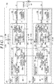
- the vehicle control system of this embodiment is a motor control system (hereinafter referred to as "ECU") configured to control an operation of a motor 11 that is a control target.
- ECU 10 controls driving of the motor 11 to apply a motor torque to, for example, a steering mechanism of a vehicle, thereby executing power steering control for assisting a driver's steering operation.
- a three-phase brushless motor is employed as the motor 11.
- the motor 11 includes motor coil groups for two systems each having three phases (U phase, V phase, and W phase). That is, the motor 11 includes a motor coil group A and a motor coil group B for two systems, which are electrically independent of each other.
- the motor coil group A and the motor coil group B have similar configurations.
- the motor 11 further includes a rotation angle sensor 12 configured to detect a rotation angle ⁇ as a condition amount indicating an operation condition (rotation condition) of the motor 11.
- the ECU 10 includes a first ECU 20 serving as a first control circuit, a second ECU 30 serving as a remaining control circuit, a first reset signal generating circuit 40, and a second reset signal generating circuit 50.
- the first ECU 20 controls electric power supply to the motor coil group A.
- the first ECU 20 is connected to a first power supply 26 configured to convert electric power from an on-board battery provided on the outside into a voltage value suitable for the first ECU 20.
- the first ECU 20 operates by being supplied with the electric power from the first power supply 26.
- a voltage sensor 27 is provided between the first ECU 20 and the first power supply 26. The voltage sensor 27 detects a voltage value V1 of the first power supply 26.
- the second ECU 30 controls electric power supply to the motor coil group B.
- the second ECU 30 is connected to a second power supply 36 configured to convert electric power from the on-board battery provided on the outside into a voltage value suitable for the second ECU 30.
- the second ECU 30 operates by being supplied with the electric power from the second power supply 36.
- a voltage sensor 37 is provided between the second ECU 30 and the second power supply 36.
- the voltage sensor 37 detects a voltage value V2 of the second power supply 36.
- the first reset signal generating circuit 40 monitors the voltage value V1 detected by the voltage sensor 27.
- the first reset signal generating circuit 40 generates a first reset signal Rs1 for keeping a control operation of the first ECU 20 in a stopped state until the voltage value V1 is stabilized.
- the second reset signal generating circuit 50 monitors the voltage value V2 detected by the voltage sensor 37.
- the second reset signal generating circuit 50 generates a second reset signal Rs2 for keeping a control operation of the second ECU 30 in a stopped state until the voltage value V2 is stabilized.
- the phrase "the voltage values V1 and V2 are stabilized" means that the voltage values V1 and V2 of the first power supply 26 and the second power supply 36 are constantly kept within a predetermined range in which the first ECU 20 and the second ECU 30 can be operated normally.
- the first reset signal generating circuit 40 and the second reset signal generating circuit 50 have the same configuration.
- the first ECU 20 and the second ECU 30 communicate with each other to synchronize their control operations.
- the ECU 10 includes the first ECU 20 and the second ECU 30 to achieve redundancy for the control system relating to the driving of the motor 11. For example, when the first ECU 20 has such an abnormality that the first ECU 20 cannot continue to control the electric power supply to the motor 11, the control performed by the first ECU 20 on the electric power supply to the motor 11 is stopped, and the electric power supply to the motor 11 is controlled only by the second ECU 30.
- the first ECU 20 and the second ECU 30 have similar configurations.
- the first ECU 20 includes an oscillator 21, a first microcomputer 22, and a first drive circuit 25.
- the oscillator 21 is formed of a crystal element or the like.
- the oscillator 21 generates a clock (triangular wave) of a fundamental frequency for determining a timing of a control operation of the first microcomputer 22.
- the first drive circuit 25 includes an inverter 25a and a current sensor 25b.
- the inverter 25a includes a plurality of switching elements such as FETs corresponding to the three phases (U phase, V phase, and W phase).
- the inverter 25a is provided such that three sets of switching arms each having two FETs connected in series are formed by being connected in parallel between a positive terminal and a negative terminal of the on-board battery.
- the current sensor 25b detects a current value I1 of each phase in an electric power supply path between the inverter 25a and the motor coil group A of the motor 11.
- the first microcomputer 22 generates a control signal Sm1 for operating the motor 11 based on the clock generated by the oscillator 21, the current value I1 detected by the current sensor 25b, and the rotation angle ⁇ detected by the rotation angle sensor 12 of the motor 11.
- the first microcomputer 22 is connected to the first power supply 26.
- the first microcomputer 22 includes a first synchronization signal generating circuit 23 and a first computation circuit 24.
- the first synchronization signal generating circuit 23 generates a first clock signal CK1 (triangular wave) serving as a synchronization signal, and a first timing signal T1 (triangular wave).
- the first clock signal CK1 is generated based on the clock generated by the oscillator 21.
- the first timing signal T1 is used for adjusting a timing of a control operation of the first computation circuit 24.
- the first synchronization signal generating circuit 23 outputs the first clock signal CK1 to the second ECU 30.
- the first synchronization signal generating circuit 23 includes a clock generator 23a, a clock output device 23b, a clock corrector 23c, and a switching device 23d.
- the clock generator 23a is a multiplier, and generates the first clock signal CK1 by multiplying the clock generated by the oscillator 21 by a predetermined multiple.
- the clock output device 23b outputs the first clock signal CK1 generated by the clock generator 23a to the second ECU 30.
- the clock corrector 23c generates a third clock signal CK3 in consideration of the first clock signal CK1 generated by the clock generator 23a and a second clock signal CK2 described later, which serves as a synchronization signal and is output from the second ECU 30.
- the switching device 23d is provided from the viewpoint of outputting the first clock signal CK1 generated by the clock generator 23a or the third clock signal CK3 generated by the clock corrector 23c to a timer generator 24a as the first timing signal T1.
- the switching device 23d outputs the first clock signal CK1 to the timer generator 24a as the first timing signal T1.
- a command signal S2 generated by a monitoring circuit 38 described later is input to the switching device 23d, the switching device 23d switches a switch to output the third clock signal CK3 generated by the clock corrector 23c to the timer generator 24a as the first timing signal T1.
- the first computation circuit 24 generates the control signal Sm1 based on the rotation angle ⁇ detected by the rotation angle sensor 12 and the current value I1 detected by the current sensor 25b.
- the first computation circuit 24 determines a timing to generate the control signal Sm1 based on the first timing signal T1.
- the first computation circuit 24 includes the timer generator 24a, an AD converter 24b, and a motor current controller 24c.
- the timer generator 24a includes a publicly-known frequency divider and a publicly-known up/down counter.
- the timer generator 24a causes the up/down counter to count up or down the first timing signal T1 whose frequency is divided by the frequency divider.
- the timer generator 24a outputs an operation trigger Tr1 to the AD converter 24b and the motor current controller 24c.
- the AD converter 24b converts an analog signal of the current value I1 detected by the current sensor 25b and the rotation angle ⁇ detected by the rotation angle sensor 12 into a digital signal Ds1 (AD conversion) based on the operation trigger Tr1.
- the AD converter 24b outputs the digital signal Ds1 to the motor current controller 24c.
- the motor current controller 24c computes a command value for operating the motor coil group A of the motor 11 from the digital signal Ds1 of the current value I1 and the rotation angle ⁇ based on the operation trigger Tr1.
- the motor current controller 24c generates the control signal Sm1 (PWM signal) based on the command value.
- the operation trigger Tr1 defines a computation timing in the motor current controller 24c, and an AD conversion timing in the AD converter 24b. Both timings are synchronized.
- the second ECU 30 includes an oscillator 31, a second microcomputer 32, and a second drive circuit 35.
- the oscillator 31 is formed of a crystal element or the like.
- the oscillator 31 generates a clock (triangular wave) of a fundamental frequency for determining a timing of a control operation of the second microcomputer 32.
- the second drive circuit 35 includes an inverter 35a and a current sensor 35b.
- the inverter 35a includes a plurality of switching elements such as FETs corresponding to the three phases (U phase, V phase, and W phase).
- the inverter 35a is provided such that three sets of switching arms each having two FETs connected in series are formed by being connected in parallel between the positive terminal and the negative terminal of the on-board battery.
- the current sensor 35b detects a current value I2 of each phase in an electric power supply path between the inverter 35a and the motor coil group B.
- the second microcomputer 32 generates a control signal Sm2 for driving the motor 11 based on the clock generated by the oscillator 31, the current value I2 detected by the current sensor 35b, and the rotation angle ⁇ detected by the rotation angle sensor 12 of the motor 11.
- the second microcomputer 32 is connected to the second power supply 36.
- the second microcomputer 32 includes a second synchronization signal generating circuit 33, a second computation circuit 34, and the monitoring circuit 38.
- the second synchronization signal generating circuit 33 generates the second clock signal CK2 (triangular wave) serving as a synchronization signal, and a second timing signal T2 (triangular wave).
- the second clock signal CK2 is generated based on the clock generated by the oscillator 31.
- the second timing signal T2 is used for adjusting a timing of a control operation of the second computation circuit 34.
- the second synchronization signal generating circuit 33 does not output the second clock signal CK2 to the first synchronization signal generating circuit 23.
- the control operation of the second microcomputer 32 is synchronized with the control operation of the first ECU 20 based on the first clock signal CK1 generated by the first synchronization signal generating circuit 23 of the first microcomputer 22. Therefore, the second synchronization signal generating circuit 33 of the second microcomputer 32 generates the second timing signal T2 in consideration of the first clock signal CK1 generated by the first synchronization signal generating circuit 23 and the second clock signal CK2 generated by the second synchronization signal generating circuit 33.
- the second synchronization signal generating circuit 33 includes a clock generator 33a, a clock output device 33b, a clock corrector 33c, and a switching device 33d.
- the clock output device 33b of the second synchronization signal generating circuit 33 does not output the second clock signal CK2 generated by the clock generator 33a to the clock corrector 23c of the first synchronization signal generating circuit 23.
- the clock output device 33b outputs the second clock signal CK2 generated by the clock generator 33a to the clock corrector 23c of the first synchronization signal generating circuit 23.
- the clock corrector 33c generates a fourth clock signal CK4 in consideration of the second clock signal CK2 generated by the clock generator 33a and the first clock signal CK1 output from the clock output device 23b of the first synchronization signal generating circuit 23.
- the generation of the third clock signal CK3 and the fourth clock signal CK4 is described in detail.
- Oscillating elements (for example, crystal elements) of the oscillators 21 and 31 have a small individual difference.
- the individual difference causes variations in the clocks of the fundamental frequencies that are output from the oscillators 21 and 31.
- a deviation may occur between the first clock signal CK1 and the second clock signal CK2 that are generated by the clock generators 23a and 33a to which the clocks are input from the oscillators 21 and 31.
- the clock deviation caused by the oscillators 21 and 31 is not eliminated, but may affect the count values of the timer generators 24a and 34a to finally cause a temporal deviation between the timings of the control operations of the first ECU 20 and the second ECU 30.
- the clock corrector 23c performs correction so that the first clock signal CK1 coincides with the second clock signal CK2, thereby generating the third clock signal CK3 in which the temporal deviation between the first clock signal CK1 and the second clock signal CK2 is suppressed.
- the clock corrector 33c performs correction so that the second clock signal CK2 coincides with the first clock signal CK1, thereby generating the fourth clock signal CK4 in which the temporal deviation between the first clock signal CK1 and the second clock signal CK2 is suppressed.
- the switching device 33d is provided from the viewpoint of outputting the second clock signal CK2 generated by the clock generator 33a or the fourth clock signal CK4 generated by the clock corrector 33c to the timer generator 34a as the second timing signal T2.
- the switching device 33d outputs the fourth clock signal CK4 to the timer generator 34a as the second timing signal T2.
- the switching device 33d switches a switch to output the second clock signal CK2 generated by the clock generator 33a to the timer generator 34a as the second timing signal T2.
- the second computation circuit 34 includes the timer generator 34a, an AD converter 34b, and a motor current controller 34c.
- the timer generator 34a causes an up/down counter to count up or down the second timing signal T2 whose frequency is divided by a frequency divider.
- the timer generator 34a outputs an operation trigger Tr2 to the AD converter 34b and the motor current controller 34c.
- the AD converter 34b converts an analog signal of the current value I2 detected by the current sensor 35b and the rotation angle ⁇ detected by the rotation angle sensor 12 into a digital signal Ds2 (AD conversion) based on the operation trigger Tr2.
- the AD converter 34b then outputs the digital signal Ds2 to the motor current controller 34c.
- the motor current controller 34c computes a command value for operating the motor coil group B of the motor 11 from the digital signal Ds2 of the current value I2 and the rotation angle ⁇ based on the operation trigger Tr2.
- the motor current controller 34c generates the control signal Sm2 (PWM signal) based on the command value.
- the monitoring circuit 38 monitors the first reset signal Rs1 generated by the first reset signal generating circuit 40 and the second reset signal Rs2 generated by the second reset signal generating circuit 50.
- the first reset signal Rs1 and the second reset signal Rs2 is described. As illustrated in FIG. 2 , when electric power starts to be supplied from the first power supply 26 and the second power supply 36 to the first ECU 20 and the second ECU 30, the voltage values VI and V2 are gradually increased. After an elapse of a predetermined time from the time when the electric power starts to be supplied from the first power supply 26 and the second power supply 36 to the first ECU 20 and the second ECU 30, the voltage values V1 and V2 are constantly kept within a predetermined range in which the first ECU 20 and the second ECU 30 can be operated normally.
- the first ECU 20 and the second ECU 30 are operated in a state in which the voltage values V1 and V2 of the first ECU 20 and the second ECU 30 are values in the vicinity of a threshold L that is a minimum value at which the first ECU 20 and the second ECU 30 can be operated.
- the voltage values V1 and V2 of the first power supply 26 and the second power supply 36 may be lower than the threshold L that is a minimum value at which the first ECU 20 and the second ECU 30 can be operated.
- the control operations of the first ECU 20 and the second ECU 30 are stopped and, accordingly, the control operation of the ECU 10 may be unstable.
- the first reset signal Rs1 and the second reset signal Rs2 are set from the viewpoint of keeping the control operations of the first ECU 20 and the second ECU 30 in a stopped state until the voltage values V1 and V2 of the first power supply 26 and the second power supply 36 are constantly kept within the predetermined range in which the first ECU 20 and the second ECU 30 can be operated normally.
- the first reset signal generating circuit 40 and the second reset signal generating circuit 50 determine that the voltage values V1 and V2 are constantly kept within the predetermined range in which the first ECU 20 and the second ECU 30 can be operated normally, the first reset signal generating circuit 40 and the second reset signal generating circuit 50 stop generating the first reset signal Rs1 and the second reset signal Rs2, thereby starting the control operations of the first ECU 20 and the second ECU 30.
- the threshold L is set as a lower limit value of the predetermined range in which the first ECU 20 and the second ECU 30 can be operated normally.
- the monitoring circuit 38 generates the command signals S1 and S2 in accordance with input statuses of the first reset signal Rs1 and the second reset signal Rs2.
- the command signals S1 and S2 are set from the viewpoint of synchronizing the control operation of the first ECU 20 with the control operation of the second ECU 30 based on the second clock signal CK2 generated by the second ECU 30 (second microcomputer 32).
- the command signal S1 is a signal for selecting the second clock signal CK2 generated by the second synchronization signal generating circuit 33 as the second timing signal T2.
- the command signal S2 is a signal for outputting the second clock signal CK2 from the second synchronization signal generating circuit 33 to the first synchronization signal generating circuit 23.
- the command signal S2 is a signal for outputting the third clock signal CK3 generated by the first synchronization signal generating circuit 23 to the timer generator 24a as the first timing signal T1.
- the monitoring circuit 38 does not generate the command signals S1 and S2. That is, when the state in which the second reset signal Rs2 is input to the monitoring circuit 38 is changed to the state in which the input of the second reset signal Rs2 is stopped, the monitoring circuit 38 does not generate the command signals S1 and S2. Description is given below of the reason why the command signals S1 and S2 are not generated when the control operation of the second microcomputer 32 returns from the stopped state to the operating state.
- the control operations of the first microcomputer 22 and the second microcomputer 32 are synchronized based on the first clock signal CK1 generated by the first microcomputer 22.
- the voltage values V1 and V2 of the first power supply 26 and the second power supply 36 may be changed (in the descending arrow direction in FIG. 2 ) to the vicinity of the threshold L that is a minimum value at which the first ECU 20 and the second ECU 30 can be operated.
- the first reset signal generating circuit 40 may determine that the voltage value V1 of the first power supply 26 is constantly kept within the predetermined range in which the first microcomputer 22 can be operated normally, and the second reset signal generating circuit 50 may determine that the voltage value V2 of the second power supply 36 is not constantly kept within the predetermined range in which the second microcomputer 32 can be operated normally.
- the first reset signal generating circuit 40 does not generate the first reset signal Rs1, and only the second reset signal generating circuit 50 generates the second reset signal Rs2. That is, the control operation of the second ECU 30 may be brought into the stopped state.
- the reason may be as follows.
- the first reset signal generating circuit 40 and the second reset signal generating circuit 50 have the same configuration, but have variations in their hardware or the like. That is, even if the voltage values V1 and V2 are changed but are constantly kept within the predetermined range in which the first ECU 20 and the second ECU 30 can be operated normally, only the second reset signal generating circuit 50 determines that the voltage value V2 is not constantly kept within the predetermined range in which the second ECU 30 can be operated normally, and only the second reset signal generating circuit 50 generates the second reset signal Rs2 because the thresholds L set in the first reset signal generating circuit 40 and the second reset signal generating circuit 50 have a slight variation.
- the control operation of the second microcomputer 32 is stopped by the second reset signal Rs2, and the first microcomputer 22 performs the control operation based on the first clock signal CK1 generated by the first microcomputer 22.
- the second reset signal generating circuit 50 determines that the voltage value V2 is constantly kept again within the predetermined range in which the second microcomputer 32 can be operated normally. Therefore, the generation of the second reset signal Rs2 is stopped. That is, the input of the second reset signal Rs2 to the monitoring circuit 38 is stopped.
- the control operation of the second microcomputer 32 is synchronized with the control operation of the first microcomputer 22 based on the first clock signal CK1 generated by the first microcomputer 22.
- the condition that the state in which the second reset signal Rs2 is input to the monitoring circuit 38 is changed to the state in which the input of the second reset signal Rs2 is stopped indicates that the control operation of the second microcomputer 32 is appropriately synchronized with the control operation of the first microcomputer 22 based on the first clock signal CK1 of the first microcomputer 22.
- the monitoring circuit 38 does not generate the command signals S1 and S2, but synchronizes the control operation of the second microcomputer 32 with the control operation of the first microcomputer 22 based on the first clock signal CK1 generated by the first microcomputer 22.
- the monitoring circuit 38 generates the command signals S1 and S2. That is, when the input of the first reset signal Rs1 is stopped after the first reset signal Rs1 is input to the monitoring circuit 38, the monitoring circuit 38 generates the command signals S1 and S2. Description is given below of the reason why the command signals S1 and S2 are generated when the control operation of the first microcomputer 22 returns from the stopped state to the operating state.
- the control operations of the first microcomputer 22 and the second microcomputer 32 are synchronized based on the first clock signal CK1 generated by the first microcomputer 22.
- the voltage values V1 and V2 of the first power supply 26 and the second power supply 36 may be changed for some reasons.
- the first reset signal generating circuit 40 may determine that the voltage value V1 of the first power supply 26 is not constantly kept within the predetermined range in which the first microcomputer 22 can be operated normally
- the second reset signal generating circuit 50 may determine that the voltage value V2 of the second power supply 36 is constantly kept within the predetermined range in which the second microcomputer 32 can be operated normally.
- only the first reset signal generating circuit 40 generates the first reset signal Rs1, and the second reset signal generating circuit 50 does not generate the second reset signal Rs2. That is, the control operation of the first microcomputer 22 may be brought into the stopped state.
- the reason may be as follows.
- the first reset signal generating circuit 40 and the second reset signal generating circuit 50 have the same configuration, but have variations in their hardware or the like. That is, even if the voltage values V1 and V2 are changed but are constantly kept within the predetermined range in which the first ECU 20 and the second ECU 30 can be operated normally, only the first reset signal generating circuit 40 determines that the voltage value V1 is not constantly kept within the predetermined range in which the first ECU 20 can be operated normally, and only the first reset signal generating circuit 40 generates the first reset signal Rs1 because the thresholds L set in the first reset signal generating circuit 40 and the second reset signal generating circuit 50 have a slight variation.
- the control operation of the first microcomputer 22 is stopped by the first reset signal Rs1, and the second microcomputer 32 needs to perform the control operation based on the second clock signal CK2 generated by the second microcomputer 32.
- the first reset signal generating circuit 40 determines that the voltage value V1 is constantly kept again within the predetermined range in which the first microcomputer 22 can be operated normally. Therefore, the generation of the first reset signal Rs1 is stopped. That is, the input of the first reset signal Rs1 to the monitoring circuit 38 is stopped.
- the control operation of the first microcomputer 22 needs to be synchronized with the control operation of the second microcomputer 32 based on the second clock signal CK2 generated by the second microcomputer 32. This is because the control operation of the second microcomputer 32 may deviate when the first clock signal CK1 is input from the first microcomputer 22 while the second microcomputer 32 is operating normally based on the second clock signal CK2.
- the condition that the state in which the first reset signal Rs1 is input to the monitoring circuit 38 is changed to the state in which the input of the first reset signal Rs1 is stopped indicates that the first microcomputer 22 needs to be synchronized based on the second clock signal CK2 of the second microcomputer 32.
- the monitoring circuit 38 determines that the control operation of the first microcomputer 22 returns from the stopped state to the operating state while the second microcomputer 32 is performing the control operation. Therefore, the monitoring circuit 38 generates the command signals S1 and S2 to synchronize the control operation of the first microcomputer 22 with the control operation of the second microcomputer 32 based on the second clock signal CK2 of the second microcomputer 32. Specifically, the monitoring circuit 38 generates the command signal S1 when only the first reset signal Rs1 is input to the monitoring circuit 38. When the state in which only the first reset signal Rs1 is input to the monitoring circuit 38 is changed to the state in which the input of the first reset signal Rs1 is stopped, the monitoring circuit 38 generates the command signal S2.
- the reason why the monitoring circuit 38 generates the command signal S1 when only the first reset signal Rs1 is input to the monitoring circuit 38 is that the second microcomputer 32 needs to perform the control operation until the first microcomputer 22 operates normally.
- the first clock signal CK1 is not input to the second microcomputer 32 until the first microcomputer 22 operates normally. That is, the reason is that the control operation of the second microcomputer 32 remains stopped as long as the fourth clock signal CK4 is set as the second timing signal T2 in the second microcomputer 32 until the first microcomputer 22 operates normally.
- the second clock signal CK2 generated by the second synchronization signal generating circuit 33 is set as the second timing signal T2.
- the second clock signal CK2 generated by the second synchronization signal generating circuit 33 is output to the first synchronization signal generating circuit 23.
- the third clock signal CK3 generated by the first synchronization signal generating circuit 23 is output to the timer generator 24a as the first timing signal T1.
- the generation of the command signals S1 and S2 by the monitoring circuit 38 is triggered under the condition that the state in which only the first reset signal Rs1 is input to the monitoring circuit 38 is changed to the state in which the input of the first reset signal Rs1 is stopped.
- the control operation of the first microcomputer 22 can be synchronized with the control operation of the second microcomputer 32 based on the second clock signal CK2 generated by the second microcomputer 32.
- the operation of the ECU 10 is described.
- the first power supply 26 and the second power supply 36 start to supply electric power to the first microcomputer 22 and the second microcomputer 32.
- the first reset signal generating circuit 40 and the second reset signal generating circuit 50 monitor the voltage values V1 and V2 of the first power supply 26 and the second power supply 36, and output the first reset signal Rs1 and the second reset signal Rs2 to the first microcomputer 22 and the second microcomputer 32 until the voltage values V1 and V2 are stabilized.
- the monitoring circuit 38 of the second microcomputer 32 monitors the first reset signal Rs1 and the second reset signal Rs2.
- the first reset signal generating circuit 40 may determine that the voltage value V1 is not constantly kept within the predetermined range in which the first ECU 20 can be operated normally. In this case, the first reset signal generating circuit 40 generates the first reset signal Rs1, and the control operation of the first ECU 20 is brought into the stopped state. Only the first reset signal Rs1 is input to the monitoring circuit 38, and therefore the monitoring circuit 38 detects that the first microcomputer 22 is in the stopped state.
- the monitoring circuit 38 When the monitoring circuit 38 detects that the control operation of the first microcomputer 22 is in the stopped state, the monitoring circuit 38 outputs the command signal S1 to the switching device 33d of the second synchronization signal generating circuit 33 of the second microcomputer 32.
- the switching device 33d switches the switch to output the second clock signal CK2 generated by the clock generator 33a to the second computation circuit 34 as the second timing signal T2.
- the monitoring circuit 38 When the first ECU 20 can be operated normally afterwards, that is, when the input of the first reset signal Rs1 to the monitoring circuit 38 is stopped afterwards, the monitoring circuit 38 outputs the command signal S2 to the clock output device 33b of the second microcomputer 32 and the switching device 23d of the first synchronization signal generating circuit 23 of the first microcomputer 22.
- the clock output device 33b When the command signal S2 is input to the clock output device 33b, the clock output device 33b outputs the second clock signal CK2 generated by the clock generator 33a to the clock corrector 23c of the first synchronization signal generating circuit 23.
- the clock corrector 23c outputs, to the switching device 23d, the third clock signal CK3 obtained by performing correction so that the first clock signal CK1 generated by the clock generator 23a coincides with the second clock signal CK2.
- the switching device 23d switches the switch to output the third clock signal CK3 generated by the clock corrector 23c to the first computation circuit 24 as the first timing signal T1.
- the monitoring circuit 38 detects that the control operation of the first microcomputer 22 returns from the stopped state to the operating state. Therefore, when the control operation of the first microcomputer 22 returns to the operating state while only the second microcomputer 32 is operating normally, the monitoring circuit 38 can synchronize the control operation of the first microcomputer 22 with the control operation of the second microcomputer 32 based on the second clock signal CK2 generated by the second microcomputer 32.
- a vehicle control system according to a second embodiment is described below. Components similar to those of the first embodiment are described by assigning the same reference symbols.
- the second embodiment is different from the first embodiment in that an initial activation state of the ECU 10 is also taken into consideration.
- the initial activation state refers to an initial state in which the ignition switch of the vehicle is turned on. As illustrated in FIG. 1 , when the ignition switch of the vehicle is turned on, electric power starts to be supplied from the first and second power supplies 26 and 36 to the first microcomputer 22 and the second microcomputer 32. Therefore, the first reset signal Rs1 and the second reset signal Rs2 are simultaneously input from the first reset signal generating circuit 40 and the second reset signal generating circuit 50 to the monitoring circuit 38.
- the monitoring circuit 38 does not generate the command signals S1 and S2. Description is given below of the reason why the monitoring circuit 38 does not generate the command signals S1 and S2 when the input of the first reset signal Rs1 and the input of the second reset signal Rs2 are simultaneously stopped.
- the first reset signal generating circuit 40 and the second reset signal generating circuit 50 When the electric power starts to be supplied from the first power supply 26 and the second power supply 36 to the first microcomputer 22 and the second microcomputer 32, the first reset signal generating circuit 40 and the second reset signal generating circuit 50 generate the first reset signal Rs1 and the second reset signal Rs2 until the voltage values V1 and V2 are stabilized. Therefore, the control operations of the first microcomputer 22 and the second microcomputer 32 are brought into a stopped state. When the voltage values V1 and V2 are stabilized and the first microcomputer 22 and the second microcomputer 32 are brought into an operating state, the control operation of the second microcomputer 32 is synchronized with the control operation of the first microcomputer 22 based on the first clock signal CK1 generated by the first microcomputer 22.
- the condition that the first reset signal Rs1 and the second reset signal Rs2 are simultaneously input to the monitoring circuit 38 and then the input of the first reset signal Rs1 and the input of the second reset signal Rs2 are simultaneously stopped indicates that the first microcomputer 22 and the second microcomputer 32 are normally activated in the so-called initial activation state of the ECU 10.
- the monitoring circuit 38 does not generate the command signals S1 and S2, but synchronizes the control operation of the second microcomputer 32 with the control operation of the first microcomputer 22 based on the first clock signal CK1 generated by the first microcomputer 22.
- the monitoring circuit 38 does not generate the command signals S1 and S2. Description is given below of the reason why the monitoring circuit 38 does not generate the command signals S1 and S2 when the state in which the first reset signal Rs1 and the second reset signal Rs2 are simultaneously input is changed to the state in which the input of the first reset signal Rs1 is stopped first and the input of the second reset signal Rs2 is stopped next.
- the condition that the input of the first reset signal Rs1 to the monitoring circuit 38 is stopped first and the input of the second reset signal Rs2 to the monitoring circuit 38 is stopped next indicates that the first microcomputer 22 starts the control operation earlier than the second microcomputer 32. Specifically, the voltage values V1 and V2 of the first microcomputer 22 and the second microcomputer 32 are gradually increased.
- the first reset signal generating circuit 40 may determine that the voltage value V1 is constantly kept within the predetermined range in which the first microcomputer 22 can be operated normally
- the second reset signal generating circuit 50 may determine that the voltage value V2 is not constantly kept within the predetermined range in which the second microcomputer 32 can be operated normally.
- the first reset signal generating circuit 40 stops generating the first reset signal Rs1 first
- the second reset signal generating circuit 50 stops generating the second reset signal Rs2 next. That is, the control operation of the second ECU 30 may be started later than the control operation of the first ECU 20.
- this situation may occur because only the second reset signal generating circuit 50 generates the second reset signal Rs2 due to the variations in the hardware or the like of the first reset signal generating circuit 40 and the second reset signal generating circuit 50.
- the first microcomputer 22 performs the control operation based on the first clock signal CK1 generated by the first microcomputer 22 until the second microcomputer 32 operates normally.
- the second reset signal generating circuit 50 determines that the voltage value V2 is kept within the predetermined range in which the second microcomputer 32 can be operated normally. Therefore, the generation of the second reset signal Rs2 is stopped. That is, the input of the second reset signal Rs2 to the monitoring circuit 38 is stopped.
- the control operation of the second microcomputer 32 is synchronized with the control operation of the first microcomputer 22 based on the first clock signal CK1 generated by the first microcomputer 22. This is because the first clock signal CK1 serving as a reference to synchronization between the control operations of the first microcomputer 22 and the second microcomputer 32 is constantly and continuously generated even if the second microcomputer 32 starts to operate later than the first microcomputer 22.
- the condition that the input of the first reset signal Rs1 to the monitoring circuit 38 is stopped first and the input of the second reset signal Rs2 to the monitoring circuit 38 is stopped next indicates that the control operation of the second microcomputer 32 is appropriately synchronized with the control operation of the first microcomputer 22 based on the first clock signal CK1 of the first microcomputer 22 in the so-called initial activation state of the ECU 10.
- the monitoring circuit 38 does not generate the command signals S1 and S2, but synchronizes the control operation of the second microcomputer 32 with the control operation of the first microcomputer 22 based on the first clock signal CK1 generated by the first microcomputer 22.
- the monitoring circuit 38 When the state in which the first reset signal Rs1 and the second reset signal Rs2 are simultaneously input to the monitoring circuit 38 is changed to the state in which the input of the second reset signal Rs2 is stopped first and the input of the first reset signal Rs1 is stopped next, the monitoring circuit 38 generates the command signals S1 and S2. Description is given below of the reason why the monitoring circuit 38 generates the command signals S1 and S2 when the state in which the first reset signal Rs1 and the second reset signal Rs2 are simultaneously input to the monitoring circuit 38 is changed to the state in which the input of the second reset signal Rs2 is stopped first and the input of the first reset signal Rs1 is stopped next.
- the condition that the input of the second reset signal Rs2 to the monitoring circuit 38 is stopped first and the input of the first reset signal Rs1 to the monitoring circuit 38 is stopped next indicates that the second microcomputer 32 starts the control operation earlier than the first microcomputer 22. Specifically, the voltage values V1 and V2 of the first microcomputer 22 and the second microcomputer 32 are gradually increased.
- the second reset signal generating circuit 50 may determine that the voltage value V2 is kept within the predetermined range in which the second microcomputer 32 can be operated normally, and the first reset signal generating circuit 40 may determine that the voltage value V1 is not kept within the predetermined range in which the first microcomputer 22 can be operated normally.
- the second reset signal generating circuit 50 stops generating the second reset signal Rs2 first, and the first reset signal generating circuit 40 stops generating the first reset signal Rs1 next. That is, the control operation of the first ECU 20 may be started later than the control operation of the second ECU 30.
- this situation may occur, for example, because the first reset signal generating circuit 40 generates the first reset signal Rs1 due to the variations in the hardware or the like of the first reset signal generating circuit 40 and the second reset signal generating circuit 50.
- the second microcomputer 32 needs to perform the control operation based on the second clock signal CK2 generated by the second microcomputer 32.
- the first reset signal generating circuit 40 determines that the voltage value V1 is kept within the predetermined range in which the first microcomputer 22 can be operated normally. Therefore, the generation of the first reset signal Rs1 is stopped. That is, the input of the first reset signal Rs1 to the monitoring circuit 38 is stopped.
- the first microcomputer 22 needs to be synchronized based on the second clock signal CK2 generated by the second microcomputer 32. This is because the control operation of the second microcomputer 32 may deviate when the first clock signal CK1 is input from the first microcomputer 22 while the second microcomputer 32 is operating normally based on the second clock signal CK2. Therefore, the condition that the input of the second reset signal Rs2 to the monitoring circuit 38 is stopped first and the input of the first reset signal Rs1 to the monitoring circuit 38 is stopped next indicates that the first microcomputer 22 needs to be synchronized based on the second clock signal CK2 of the second microcomputer 32 in the so-called initial activation state of the ECU 10.
- the monitoring circuit 38 determines that the control operation of the first microcomputer 22 is changed from the stopped state to the operating state while the second microcomputer 32 is performing the control operation. Therefore, the monitoring circuit 38 generates the command signals S1 and S2 to synchronize the control operation of the first microcomputer 22 with the control operation of the second microcomputer 32 based on the second clock signal CK2 of the second microcomputer 32. Specifically, the monitoring circuit 38 generates the command signal S1 when only the first reset signal Rs1 is input to the monitoring circuit 38.
- the monitoring circuit 38 When the state in which only the first reset signal Rs1 is input to the monitoring circuit 38 is changed to the state in which the input of the first reset signal Rs1 is stopped, the monitoring circuit 38 generates the command signal S2.
- the reason why the monitoring circuit 38 generates the command signal S1 when only the first reset signal Rs1 is input to the monitoring circuit 38 is that the second microcomputer 32 needs to perform the control operation until the first microcomputer 22 operates normally. That is, the reason is that the control operation of the second microcomputer 32 remains stopped as long as the fourth clock signal CK4 is set as the second timing signal T2 in the second microcomputer 32 until the first microcomputer 22 operates normally.
- the second clock signal CK2 generated by the second synchronization signal generating circuit 33 is set as the second timing signal T2.
- the second clock signal CK2 generated by the second synchronization signal generating circuit 33 is output to the first synchronization signal generating circuit 23.
- the third clock signal CK3 generated by the first synchronization signal generating circuit 23 is output to the timer generator 24a as the first timing signal T1.
- the synchronization control for the first ECU 20 and the second ECU 30 for example, when the ECU 10 is in the initial activation state as well as when the state in which the ECU 10 is operating normally is changed to the state in which the control operation of the first ECU 20 is brought into the stopped state and then returns to the operating state.
- a vehicle control system according to a third embodiment is described below. Components similar to those of the first embodiment are described by assigning the same reference symbols.
- the AD converter 34b of the second microcomputer 32 performs conversion to obtain a digital signal Ds3 from an analog signal of the voltage value V1 detected by the voltage sensor 27 provided between the first microcomputer 22 and the first power supply 26. Further, the AD converter 34b performs conversion to obtain a digital signal Ds4 from an analog signal of the voltage value V2 detected by the voltage sensor 37 provided between the second microcomputer 32 and the second power supply 36.
- the monitoring circuit 38 monitors the digital signals Ds3 and Ds4. The monitoring circuit 38 outputs the command signals S1 and S2 to the second synchronization signal generating circuit 33 in accordance with input statuses of the digital signals Ds3 and Ds4.
- the AD converter 34b converts the voltage value V1 into a digital signal Ds3 indicating "1".
- the AD converter 34b converts the voltage value V1 into a digital signal Ds3 indicating "0".
- the AD converter 34b similarly converts the voltage value V2 of the second power supply 36 into a digital signal Ds4 indicating "1" or "0".
- the monitoring circuit 38 When the state in which the first microcomputer 22 and the second microcomputer 32 operate normally is changed to the state in which the control operation of the first microcomputer 22 is brought into the stopped state and returns to the operating state , the monitoring circuit 38 generates the command signals S1 and S2. That is, the monitoring circuit 38 generates the command signals S1 and S2 when the input of the digital signal Ds3 is changed from “1" to "0” and then from "0" to "1" again while the digital signal Ds4 indicating "1" is not changed.
- the generation of the command signals S1 and S2 by the monitoring circuit 38 is triggered under the condition that the input of the digital signal Ds3 is changed from “0" to "1” while the digital signal Ds4 indicating "1" is input to the monitoring circuit 38.
- the control operation of the first microcomputer 22 can be synchronized with the control operation of the second microcomputer 32 based on the second clock signal CK2 generated by the second microcomputer 32.
- This embodiment may be modified as follows without causing any technical contradiction.
- the third embodiment is described under the assumption that the ECU 10 operates normally. For example, the case where the ECU 10 is in the initial activation state may be taken into consideration.
- the ignition switch of the vehicle is turned on and electric power starts to be supplied from the first power supply 26 and the second power supply 36 to the first microcomputer 22 and the second microcomputer 32. Therefore, the digital signal Ds3 indicating "0" and the digital signal Ds4 indicating “0” are simultaneously input from the AD converter 34b to the monitoring circuit 38.
- the monitoring circuit 38 When the input of the digital signal Ds4 is changed from “0" to "1” first and the input of the digital signal Ds3 is changed from "0" to "1” next, the monitoring circuit 38 generates the command signals S1 and S2. In this case as well, effects similar to those of the third embodiment are attained.
- the monitoring circuit 38 detects that the control operation of the first microcomputer 22 is changed from the stopped state to the operating state based on the input statuses of the first reset signal Rs1 and the second reset signal Rs2 in the first and second embodiments, or based on the input statuses of the digital signals Ds3 and Ds4 of the voltage values V1 and V2 in the third embodiment.
- the present invention is not limited to those cases.
- the monitoring circuit 38 may detect that the control operation of the first microcomputer 22 is changed from the stopped state to the operating state based on the first clock signal CK1 output from the clock output device 23b of the first microcomputer 22.
- the first clock signal CK1 is not output from the clock output device 23b.
- the first clock signal CK1 is output from the clock output device 23b.
- the monitoring circuit 38 may detect that the control operation of the first microcomputer 22 is in the stopped state when the input of the first clock signal CK1 is stopped, or may detect that the control operation of the first microcomputer 22 is in the operating state when the first clock signal CK1 is input.
- the control target is the single motor 11 including the motor coil group A and the motor coil group B for two systems, which are electrically independent of each other.
- the control target may be two motors each including a single motor coil group for one system having the three phases (U phase, V phase, and W phase).
- the motor 11 may include three or more motor coil groups for systems each having the three phases (U phase, V phase, and W phase).
- the ECU 10 is provided with control circuits including microcomputers as many as the motor coil groups.
- the ECU 10 includes the control circuits for two systems, which are the first ECU 20 and the second ECU 30.
- the present invention is not limited to this case.
- the ECU 10 may include control circuits for three or more systems.
- at least one of the remaining control circuits except the first ECU 20 serving as the first control circuit is set so as to have the monitoring circuit 38.
- the control operation of the first ECU 20 is synchronized with the control operation of the remaining control circuits based on the clock signal serving as a synchronization signal generated by the remaining control circuits.
- the monitoring circuit 38 is provided inside the second microcomputer 32.
- the present invention is not limited to this case.
- the monitoring circuit 38 may be provided at any location inside the second ECU 30.
- the control circuits for three or more systems are provided as described above, the monitoring circuit 38 may be provided at any location inside the control circuit instead of being provided inside the microcomputer.
Landscapes
- Engineering & Computer Science (AREA)
- Mechanical Engineering (AREA)
- Power Engineering (AREA)
- Transportation (AREA)
- Theoretical Computer Science (AREA)
- Sustainable Energy (AREA)
- Sustainable Development (AREA)
- Life Sciences & Earth Sciences (AREA)
- Computing Systems (AREA)
- General Physics & Mathematics (AREA)
- General Engineering & Computer Science (AREA)
- Physics & Mathematics (AREA)
- Quality & Reliability (AREA)
- Chemical & Material Sciences (AREA)
- Combustion & Propulsion (AREA)
- Power Steering Mechanism (AREA)
- Control Of Ac Motors In General (AREA)
- Debugging And Monitoring (AREA)
- Electric Propulsion And Braking For Vehicles (AREA)
Applications Claiming Priority (1)
| Application Number | Priority Date | Filing Date | Title |
|---|---|---|---|
| JP2017077434A JP6848632B2 (ja) | 2017-04-10 | 2017-04-10 | 車両制御装置 |
Publications (2)
| Publication Number | Publication Date |
|---|---|
| EP3388280A1 true EP3388280A1 (de) | 2018-10-17 |
| EP3388280B1 EP3388280B1 (de) | 2021-11-24 |
Family
ID=62046637
Family Applications (1)
| Application Number | Title | Priority Date | Filing Date |
|---|---|---|---|
| EP18166104.2A Not-in-force EP3388280B1 (de) | 2017-04-10 | 2018-04-06 | Fahrzeugsteuerungssystem umfassend synchronisierte steuerungsschaltungen |
Country Status (4)
| Country | Link |
|---|---|
| US (1) | US10266129B2 (de) |
| EP (1) | EP3388280B1 (de) |
| JP (1) | JP6848632B2 (de) |
| CN (1) | CN108688717B (de) |
Families Citing this family (5)
| Publication number | Priority date | Publication date | Assignee | Title |
|---|---|---|---|---|
| US10668945B2 (en) * | 2016-07-11 | 2020-06-02 | Denso Corporation | Motor control apparatus, motor drive system, and motor control method |
| CN113228491A (zh) * | 2018-12-28 | 2021-08-06 | 日本电产株式会社 | 驱动控制装置、马达驱动装置及助力转向装置 |
| US12212163B2 (en) * | 2019-07-25 | 2025-01-28 | Samsung Sdi Co., Ltd. | Battery system |
| US11958622B2 (en) * | 2020-05-15 | 2024-04-16 | Pratt & Whitney Canada Corp. | Protection functions |
| JP2023132636A (ja) * | 2022-03-11 | 2023-09-22 | 新電元工業株式会社 | 電源装置 |
Citations (5)
| Publication number | Priority date | Publication date | Assignee | Title |
|---|---|---|---|---|
| JP2005102394A (ja) * | 2003-09-24 | 2005-04-14 | Yaskawa Electric Corp | 二重巻線交流電動機の制御方法 |
| JP2007267510A (ja) * | 2006-03-28 | 2007-10-11 | Kawasaki Heavy Ind Ltd | インバータ駆動装置および駆動方法 |
| WO2010061918A1 (ja) | 2008-11-27 | 2010-06-03 | 日立オートモティブシステムズ株式会社 | 電動機制御装置および運転制御方法 |
| EP2275322A2 (de) * | 2009-07-13 | 2011-01-19 | Jtekt Corporation | Elektrische Servolenkung |
| EP2897285A2 (de) * | 2013-12-31 | 2015-07-22 | LSIS Co., Ltd. | Verfahren zur Steuerung von parallel geschalteten Umrichtern |
Family Cites Families (9)
| Publication number | Priority date | Publication date | Assignee | Title |
|---|---|---|---|---|
| JP2002354871A (ja) * | 2001-05-25 | 2002-12-06 | Mitsubishi Electric Corp | 電動パワーステアリング装置 |
| DE60311806T2 (de) * | 2002-06-11 | 2007-10-31 | Tyco Healthcare Group Lp, Norwalk | Klammer zur Befestigung von Hernia-Netz |
| EP2518890B1 (de) * | 2009-12-25 | 2017-03-01 | Toyota Jidosha Kabushiki Kaisha | Elektrische servolenkvorrichtung |
| WO2013190609A1 (ja) * | 2012-06-18 | 2013-12-27 | 三菱電機株式会社 | インバータシステム、及び通信方法 |
| WO2016135840A1 (ja) * | 2015-02-24 | 2016-09-01 | 三菱電機株式会社 | 電動駆動装置、及び電動パワーステアリング装置 |
| JP6540227B2 (ja) * | 2015-05-21 | 2019-07-10 | 株式会社ジェイテクト | 車両用制御装置 |
| JP6361589B2 (ja) * | 2015-06-11 | 2018-07-25 | 株式会社デンソー | 通信システム |
| US10128783B2 (en) * | 2016-05-31 | 2018-11-13 | Infineon Technologies Ag | Synchronization of internal oscillators of components sharing a communications bus |
| JP7024223B2 (ja) * | 2016-07-11 | 2022-02-24 | 株式会社デンソー | モータ制御装置、モータ駆動システム、及び、モータ制御方法 |
-
2017
- 2017-04-10 JP JP2017077434A patent/JP6848632B2/ja not_active Expired - Fee Related
-
2018
- 2018-04-03 US US15/943,829 patent/US10266129B2/en active Active
- 2018-04-06 EP EP18166104.2A patent/EP3388280B1/de not_active Not-in-force
- 2018-04-10 CN CN201810315513.XA patent/CN108688717B/zh not_active Expired - Fee Related
Patent Citations (5)
| Publication number | Priority date | Publication date | Assignee | Title |
|---|---|---|---|---|
| JP2005102394A (ja) * | 2003-09-24 | 2005-04-14 | Yaskawa Electric Corp | 二重巻線交流電動機の制御方法 |
| JP2007267510A (ja) * | 2006-03-28 | 2007-10-11 | Kawasaki Heavy Ind Ltd | インバータ駆動装置および駆動方法 |
| WO2010061918A1 (ja) | 2008-11-27 | 2010-06-03 | 日立オートモティブシステムズ株式会社 | 電動機制御装置および運転制御方法 |
| EP2275322A2 (de) * | 2009-07-13 | 2011-01-19 | Jtekt Corporation | Elektrische Servolenkung |
| EP2897285A2 (de) * | 2013-12-31 | 2015-07-22 | LSIS Co., Ltd. | Verfahren zur Steuerung von parallel geschalteten Umrichtern |
Also Published As
| Publication number | Publication date |
|---|---|
| US20180290605A1 (en) | 2018-10-11 |
| JP6848632B2 (ja) | 2021-03-24 |
| JP2018182859A (ja) | 2018-11-15 |
| EP3388280B1 (de) | 2021-11-24 |
| US10266129B2 (en) | 2019-04-23 |
| CN108688717B (zh) | 2022-05-27 |
| CN108688717A (zh) | 2018-10-23 |
Similar Documents
| Publication | Publication Date | Title |
|---|---|---|
| EP3388280B1 (de) | Fahrzeugsteuerungssystem umfassend synchronisierte steuerungsschaltungen | |
| US10654518B2 (en) | Motor control apparatus, motor drive system, and motor control method | |
| US11539313B2 (en) | System and method of synchronizing a switching signal | |
| US11242087B2 (en) | Motor control apparatus, motor drive system, and motor control method | |
| EP3624330B1 (de) | Motorsteuerungsvorrichtung | |
| JP5412095B2 (ja) | 電動機制御装置および運転制御方法 | |
| US10668945B2 (en) | Motor control apparatus, motor drive system, and motor control method | |
| US11472473B2 (en) | Motor control device, motor drive system and motor control method | |
| US10128783B2 (en) | Synchronization of internal oscillators of components sharing a communications bus | |
| JP7239030B2 (ja) | モータ制御装置 | |
| US11518435B2 (en) | Motor control apparatus and motor driving system | |
| CN115447663A (zh) | 具有至少两个控制设备的机动车辆电子系统及其控制方法 | |
| JP6630022B2 (ja) | 電動機のためのスイッチ装置、制御装置、ステアリングシステム | |
| CN109905028B (zh) | 转换器控制系统 | |
| JP6758494B2 (ja) | 回転角度検出装置および交流回転機制御装置 | |
| JP2020077276A (ja) | 半導体装置、制御装置および制御方法 | |
| JP2017184388A (ja) | モータ制御装置 | |
| CN115230619B (zh) | 通信系统 | |
| CN111492571A (zh) | 用于双通道电机控制器的定时器电路 | |
| WO2026058491A1 (ja) | モータ制御装置およびモータ制御方法 |
Legal Events
| Date | Code | Title | Description |
|---|---|---|---|
| PUAI | Public reference made under article 153(3) epc to a published international application that has entered the european phase |
Free format text: ORIGINAL CODE: 0009012 |
|
| STAA | Information on the status of an ep patent application or granted ep patent |
Free format text: STATUS: THE APPLICATION HAS BEEN PUBLISHED |
|
| AK | Designated contracting states |
Kind code of ref document: A1 Designated state(s): AL AT BE BG CH CY CZ DE DK EE ES FI FR GB GR HR HU IE IS IT LI LT LU LV MC MK MT NL NO PL PT RO RS SE SI SK SM TR |
|
| AX | Request for extension of the european patent |
Extension state: BA ME |
|
| STAA | Information on the status of an ep patent application or granted ep patent |
Free format text: STATUS: REQUEST FOR EXAMINATION WAS MADE |
|
| 17P | Request for examination filed |
Effective date: 20190319 |
|
| RBV | Designated contracting states (corrected) |
Designated state(s): AL AT BE BG CH CY CZ DE DK EE ES FI FR GB GR HR HU IE IS IT LI LT LU LV MC MK MT NL NO PL PT RO RS SE SI SK SM TR |
|
| STAA | Information on the status of an ep patent application or granted ep patent |
Free format text: STATUS: EXAMINATION IS IN PROGRESS |
|
| 17Q | First examination report despatched |
Effective date: 20201106 |
|
| REG | Reference to a national code |
Ref country code: DE Ref legal event code: R079 Ref document number: 602018027027 Country of ref document: DE Free format text: PREVIOUS MAIN CLASS: B60L0011180000 Ipc: B60L0015000000 |
|
| GRAP | Despatch of communication of intention to grant a patent |
Free format text: ORIGINAL CODE: EPIDOSNIGR1 |
|
| RIC1 | Information provided on ipc code assigned before grant |
Ipc: B60L 15/00 20060101AFI20210506BHEP Ipc: B60L 15/02 20060101ALI20210506BHEP Ipc: G05B 11/00 20060101ALI20210506BHEP Ipc: H02P 27/00 20060101ALI20210506BHEP Ipc: H02M 7/00 20060101ALI20210506BHEP Ipc: B60L 50/51 20190101ALI20210506BHEP Ipc: H02M 1/32 20070101ALI20210506BHEP Ipc: H02P 27/04 20160101ALI20210506BHEP |
|
| STAA | Information on the status of an ep patent application or granted ep patent |
Free format text: STATUS: GRANT OF PATENT IS INTENDED |
|
| INTG | Intention to grant announced |
Effective date: 20210609 |
|
| GRAS | Grant fee paid |
Free format text: ORIGINAL CODE: EPIDOSNIGR3 |
|
| GRAA | (expected) grant |
Free format text: ORIGINAL CODE: 0009210 |
|
| STAA | Information on the status of an ep patent application or granted ep patent |
Free format text: STATUS: THE PATENT HAS BEEN GRANTED |
|
| AK | Designated contracting states |
Kind code of ref document: B1 Designated state(s): AL AT BE BG CH CY CZ DE DK EE ES FI FR GB GR HR HU IE IS IT LI LT LU LV MC MK MT NL NO PL PT RO RS SE SI SK SM TR |
|
| REG | Reference to a national code |
Ref country code: GB Ref legal event code: FG4D |
|
| RIN1 | Information on inventor provided before grant (corrected) |
Inventor name: FUJITA, YUJI Inventor name: MIKAMO, SATORU Inventor name: ITO, TAKEHIRO |
|
| REG | Reference to a national code |
Ref country code: AT Ref legal event code: REF Ref document number: 1449621 Country of ref document: AT Kind code of ref document: T Effective date: 20211215 |
|
| REG | Reference to a national code |
Ref country code: DE Ref legal event code: R096 Ref document number: 602018027027 Country of ref document: DE |
|
| REG | Reference to a national code |
Ref country code: IE Ref legal event code: FG4D |
|
| REG | Reference to a national code |
Ref country code: LT Ref legal event code: MG9D |
|
| RAP4 | Party data changed (patent owner data changed or rights of a patent transferred) |
Owner name: JTEKT CORPORATION |
|
| REG | Reference to a national code |
Ref country code: NL Ref legal event code: MP Effective date: 20211124 |
|
| REG | Reference to a national code |
Ref country code: AT Ref legal event code: MK05 Ref document number: 1449621 Country of ref document: AT Kind code of ref document: T Effective date: 20211124 |
|
| PG25 | Lapsed in a contracting state [announced via postgrant information from national office to epo] |
Ref country code: RS Free format text: LAPSE BECAUSE OF FAILURE TO SUBMIT A TRANSLATION OF THE DESCRIPTION OR TO PAY THE FEE WITHIN THE PRESCRIBED TIME-LIMIT Effective date: 20211124 Ref country code: LT Free format text: LAPSE BECAUSE OF FAILURE TO SUBMIT A TRANSLATION OF THE DESCRIPTION OR TO PAY THE FEE WITHIN THE PRESCRIBED TIME-LIMIT Effective date: 20211124 Ref country code: FI Free format text: LAPSE BECAUSE OF FAILURE TO SUBMIT A TRANSLATION OF THE DESCRIPTION OR TO PAY THE FEE WITHIN THE PRESCRIBED TIME-LIMIT Effective date: 20211124 Ref country code: BG Free format text: LAPSE BECAUSE OF FAILURE TO SUBMIT A TRANSLATION OF THE DESCRIPTION OR TO PAY THE FEE WITHIN THE PRESCRIBED TIME-LIMIT Effective date: 20220224 Ref country code: AT Free format text: LAPSE BECAUSE OF FAILURE TO SUBMIT A TRANSLATION OF THE DESCRIPTION OR TO PAY THE FEE WITHIN THE PRESCRIBED TIME-LIMIT Effective date: 20211124 |
|
| PG25 | Lapsed in a contracting state [announced via postgrant information from national office to epo] |
Ref country code: IS Free format text: LAPSE BECAUSE OF FAILURE TO SUBMIT A TRANSLATION OF THE DESCRIPTION OR TO PAY THE FEE WITHIN THE PRESCRIBED TIME-LIMIT Effective date: 20220324 Ref country code: SE Free format text: LAPSE BECAUSE OF FAILURE TO SUBMIT A TRANSLATION OF THE DESCRIPTION OR TO PAY THE FEE WITHIN THE PRESCRIBED TIME-LIMIT Effective date: 20211124 Ref country code: PT Free format text: LAPSE BECAUSE OF FAILURE TO SUBMIT A TRANSLATION OF THE DESCRIPTION OR TO PAY THE FEE WITHIN THE PRESCRIBED TIME-LIMIT Effective date: 20220324 Ref country code: PL Free format text: LAPSE BECAUSE OF FAILURE TO SUBMIT A TRANSLATION OF THE DESCRIPTION OR TO PAY THE FEE WITHIN THE PRESCRIBED TIME-LIMIT Effective date: 20211124 Ref country code: NO Free format text: LAPSE BECAUSE OF FAILURE TO SUBMIT A TRANSLATION OF THE DESCRIPTION OR TO PAY THE FEE WITHIN THE PRESCRIBED TIME-LIMIT Effective date: 20220224 Ref country code: NL Free format text: LAPSE BECAUSE OF FAILURE TO SUBMIT A TRANSLATION OF THE DESCRIPTION OR TO PAY THE FEE WITHIN THE PRESCRIBED TIME-LIMIT Effective date: 20211124 Ref country code: LV Free format text: LAPSE BECAUSE OF FAILURE TO SUBMIT A TRANSLATION OF THE DESCRIPTION OR TO PAY THE FEE WITHIN THE PRESCRIBED TIME-LIMIT Effective date: 20211124 Ref country code: HR Free format text: LAPSE BECAUSE OF FAILURE TO SUBMIT A TRANSLATION OF THE DESCRIPTION OR TO PAY THE FEE WITHIN THE PRESCRIBED TIME-LIMIT Effective date: 20211124 Ref country code: GR Free format text: LAPSE BECAUSE OF FAILURE TO SUBMIT A TRANSLATION OF THE DESCRIPTION OR TO PAY THE FEE WITHIN THE PRESCRIBED TIME-LIMIT Effective date: 20220225 Ref country code: ES Free format text: LAPSE BECAUSE OF FAILURE TO SUBMIT A TRANSLATION OF THE DESCRIPTION OR TO PAY THE FEE WITHIN THE PRESCRIBED TIME-LIMIT Effective date: 20211124 |
|
| PG25 | Lapsed in a contracting state [announced via postgrant information from national office to epo] |
Ref country code: SM Free format text: LAPSE BECAUSE OF FAILURE TO SUBMIT A TRANSLATION OF THE DESCRIPTION OR TO PAY THE FEE WITHIN THE PRESCRIBED TIME-LIMIT Effective date: 20211124 Ref country code: SK Free format text: LAPSE BECAUSE OF FAILURE TO SUBMIT A TRANSLATION OF THE DESCRIPTION OR TO PAY THE FEE WITHIN THE PRESCRIBED TIME-LIMIT Effective date: 20211124 Ref country code: RO Free format text: LAPSE BECAUSE OF FAILURE TO SUBMIT A TRANSLATION OF THE DESCRIPTION OR TO PAY THE FEE WITHIN THE PRESCRIBED TIME-LIMIT Effective date: 20211124 Ref country code: EE Free format text: LAPSE BECAUSE OF FAILURE TO SUBMIT A TRANSLATION OF THE DESCRIPTION OR TO PAY THE FEE WITHIN THE PRESCRIBED TIME-LIMIT Effective date: 20211124 Ref country code: DK Free format text: LAPSE BECAUSE OF FAILURE TO SUBMIT A TRANSLATION OF THE DESCRIPTION OR TO PAY THE FEE WITHIN THE PRESCRIBED TIME-LIMIT Effective date: 20211124 Ref country code: CZ Free format text: LAPSE BECAUSE OF FAILURE TO SUBMIT A TRANSLATION OF THE DESCRIPTION OR TO PAY THE FEE WITHIN THE PRESCRIBED TIME-LIMIT Effective date: 20211124 |
|
| REG | Reference to a national code |
Ref country code: DE Ref legal event code: R097 Ref document number: 602018027027 Country of ref document: DE |
|
| PLBE | No opposition filed within time limit |
Free format text: ORIGINAL CODE: 0009261 |
|
| STAA | Information on the status of an ep patent application or granted ep patent |
Free format text: STATUS: NO OPPOSITION FILED WITHIN TIME LIMIT |
|
| PG25 | Lapsed in a contracting state [announced via postgrant information from national office to epo] |
Ref country code: AL Free format text: LAPSE BECAUSE OF FAILURE TO SUBMIT A TRANSLATION OF THE DESCRIPTION OR TO PAY THE FEE WITHIN THE PRESCRIBED TIME-LIMIT Effective date: 20211124 |
|
| 26N | No opposition filed |
Effective date: 20220825 |
|
| PG25 | Lapsed in a contracting state [announced via postgrant information from national office to epo] |
Ref country code: SI Free format text: LAPSE BECAUSE OF FAILURE TO SUBMIT A TRANSLATION OF THE DESCRIPTION OR TO PAY THE FEE WITHIN THE PRESCRIBED TIME-LIMIT Effective date: 20211124 |
|
| REG | Reference to a national code |
Ref country code: CH Ref legal event code: PL |
|
| GBPC | Gb: european patent ceased through non-payment of renewal fee |
Effective date: 20220406 |
|
| REG | Reference to a national code |
Ref country code: BE Ref legal event code: MM Effective date: 20220430 |
|
| PG25 | Lapsed in a contracting state [announced via postgrant information from national office to epo] |
Ref country code: MC Free format text: LAPSE BECAUSE OF FAILURE TO SUBMIT A TRANSLATION OF THE DESCRIPTION OR TO PAY THE FEE WITHIN THE PRESCRIBED TIME-LIMIT Effective date: 20211124 Ref country code: LU Free format text: LAPSE BECAUSE OF NON-PAYMENT OF DUE FEES Effective date: 20220406 Ref country code: LI Free format text: LAPSE BECAUSE OF NON-PAYMENT OF DUE FEES Effective date: 20220430 Ref country code: GB Free format text: LAPSE BECAUSE OF NON-PAYMENT OF DUE FEES Effective date: 20220406 Ref country code: CH Free format text: LAPSE BECAUSE OF NON-PAYMENT OF DUE FEES Effective date: 20220430 |
|
| PG25 | Lapsed in a contracting state [announced via postgrant information from national office to epo] |
Ref country code: BE Free format text: LAPSE BECAUSE OF NON-PAYMENT OF DUE FEES Effective date: 20220430 |
|
| PG25 | Lapsed in a contracting state [announced via postgrant information from national office to epo] |
Ref country code: IE Free format text: LAPSE BECAUSE OF NON-PAYMENT OF DUE FEES Effective date: 20220406 |
|
| PG25 | Lapsed in a contracting state [announced via postgrant information from national office to epo] |
Ref country code: IT Free format text: LAPSE BECAUSE OF FAILURE TO SUBMIT A TRANSLATION OF THE DESCRIPTION OR TO PAY THE FEE WITHIN THE PRESCRIBED TIME-LIMIT Effective date: 20211124 |
|
| PG25 | Lapsed in a contracting state [announced via postgrant information from national office to epo] |
Ref country code: HU Free format text: LAPSE BECAUSE OF FAILURE TO SUBMIT A TRANSLATION OF THE DESCRIPTION OR TO PAY THE FEE WITHIN THE PRESCRIBED TIME-LIMIT; INVALID AB INITIO Effective date: 20180406 |
|
| PG25 | Lapsed in a contracting state [announced via postgrant information from national office to epo] |
Ref country code: MK Free format text: LAPSE BECAUSE OF FAILURE TO SUBMIT A TRANSLATION OF THE DESCRIPTION OR TO PAY THE FEE WITHIN THE PRESCRIBED TIME-LIMIT Effective date: 20211124 Ref country code: CY Free format text: LAPSE BECAUSE OF FAILURE TO SUBMIT A TRANSLATION OF THE DESCRIPTION OR TO PAY THE FEE WITHIN THE PRESCRIBED TIME-LIMIT Effective date: 20211124 |
|
| PGFP | Annual fee paid to national office [announced via postgrant information from national office to epo] |
Ref country code: FR Payment date: 20240308 Year of fee payment: 7 |
|
| PGFP | Annual fee paid to national office [announced via postgrant information from national office to epo] |
Ref country code: DE Payment date: 20240227 Year of fee payment: 7 |
|
| PG25 | Lapsed in a contracting state [announced via postgrant information from national office to epo] |
Ref country code: MT Free format text: LAPSE BECAUSE OF FAILURE TO SUBMIT A TRANSLATION OF THE DESCRIPTION OR TO PAY THE FEE WITHIN THE PRESCRIBED TIME-LIMIT Effective date: 20211124 |
|
| REG | Reference to a national code |
Ref country code: DE Ref legal event code: R119 Ref document number: 602018027027 Country of ref document: DE |
|
| PG25 | Lapsed in a contracting state [announced via postgrant information from national office to epo] |
Ref country code: TR Free format text: LAPSE BECAUSE OF FAILURE TO SUBMIT A TRANSLATION OF THE DESCRIPTION OR TO PAY THE FEE WITHIN THE PRESCRIBED TIME-LIMIT Effective date: 20211124 |
|
| PG25 | Lapsed in a contracting state [announced via postgrant information from national office to epo] |
Ref country code: DE Free format text: LAPSE BECAUSE OF NON-PAYMENT OF DUE FEES Effective date: 20251104 |
|
| PG25 | Lapsed in a contracting state [announced via postgrant information from national office to epo] |
Ref country code: FR Free format text: LAPSE BECAUSE OF NON-PAYMENT OF DUE FEES Effective date: 20250430 |