EP3388403B1 - Verbundglas - Google Patents
Verbundglas Download PDFInfo
- Publication number
- EP3388403B1 EP3388403B1 EP16873060.4A EP16873060A EP3388403B1 EP 3388403 B1 EP3388403 B1 EP 3388403B1 EP 16873060 A EP16873060 A EP 16873060A EP 3388403 B1 EP3388403 B1 EP 3388403B1
- Authority
- EP
- European Patent Office
- Prior art keywords
- laminated glass
- glass
- film
- intermediate bonding
- pair
- Prior art date
- Legal status (The legal status is an assumption and is not a legal conclusion. Google has not performed a legal analysis and makes no representation as to the accuracy of the status listed.)
- Active
Links
Images

Classifications
-
- B—PERFORMING OPERATIONS; TRANSPORTING
- B32—LAYERED PRODUCTS
- B32B—LAYERED PRODUCTS, i.e. PRODUCTS BUILT-UP OF STRATA OF FLAT OR NON-FLAT, e.g. CELLULAR OR HONEYCOMB, FORM
- B32B17/00—Layered products essentially comprising sheet glass, or glass, slag, or like fibres
- B32B17/06—Layered products essentially comprising sheet glass, or glass, slag, or like fibres comprising glass as the main or only constituent of a layer, next to another layer of a specific material
- B32B17/10—Layered products essentially comprising sheet glass, or glass, slag, or like fibres comprising glass as the main or only constituent of a layer, next to another layer of a specific material of synthetic resin
- B32B17/10005—Layered products essentially comprising sheet glass, or glass, slag, or like fibres comprising glass as the main or only constituent of a layer, next to another layer of a specific material of synthetic resin laminated safety glass or glazing
- B32B17/10009—Layered products essentially comprising sheet glass, or glass, slag, or like fibres comprising glass as the main or only constituent of a layer, next to another layer of a specific material of synthetic resin laminated safety glass or glazing characterized by the number, the constitution or treatment of glass sheets
- B32B17/10036—Layered products essentially comprising sheet glass, or glass, slag, or like fibres comprising glass as the main or only constituent of a layer, next to another layer of a specific material of synthetic resin laminated safety glass or glazing characterized by the number, the constitution or treatment of glass sheets comprising two outer glass sheets
-
- B—PERFORMING OPERATIONS; TRANSPORTING
- B32—LAYERED PRODUCTS
- B32B—LAYERED PRODUCTS, i.e. PRODUCTS BUILT-UP OF STRATA OF FLAT OR NON-FLAT, e.g. CELLULAR OR HONEYCOMB, FORM
- B32B17/00—Layered products essentially comprising sheet glass, or glass, slag, or like fibres
- B32B17/06—Layered products essentially comprising sheet glass, or glass, slag, or like fibres comprising glass as the main or only constituent of a layer, next to another layer of a specific material
- B32B17/10—Layered products essentially comprising sheet glass, or glass, slag, or like fibres comprising glass as the main or only constituent of a layer, next to another layer of a specific material of synthetic resin
- B32B17/10005—Layered products essentially comprising sheet glass, or glass, slag, or like fibres comprising glass as the main or only constituent of a layer, next to another layer of a specific material of synthetic resin laminated safety glass or glazing
- B32B17/10165—Functional features of the laminated safety glass or glazing
- B32B17/10293—Edge features, e.g. inserts or holes
- B32B17/10302—Edge sealing
-
- B—PERFORMING OPERATIONS; TRANSPORTING
- B32—LAYERED PRODUCTS
- B32B—LAYERED PRODUCTS, i.e. PRODUCTS BUILT-UP OF STRATA OF FLAT OR NON-FLAT, e.g. CELLULAR OR HONEYCOMB, FORM
- B32B17/00—Layered products essentially comprising sheet glass, or glass, slag, or like fibres
- B32B17/06—Layered products essentially comprising sheet glass, or glass, slag, or like fibres comprising glass as the main or only constituent of a layer, next to another layer of a specific material
- B32B17/10—Layered products essentially comprising sheet glass, or glass, slag, or like fibres comprising glass as the main or only constituent of a layer, next to another layer of a specific material of synthetic resin
- B32B17/10005—Layered products essentially comprising sheet glass, or glass, slag, or like fibres comprising glass as the main or only constituent of a layer, next to another layer of a specific material of synthetic resin laminated safety glass or glazing
- B32B17/10165—Functional features of the laminated safety glass or glazing
- B32B17/10339—Specific parts of the laminated safety glass or glazing being colored or tinted
- B32B17/10348—Specific parts of the laminated safety glass or glazing being colored or tinted comprising an obscuration band
-
- B—PERFORMING OPERATIONS; TRANSPORTING
- B32—LAYERED PRODUCTS
- B32B—LAYERED PRODUCTS, i.e. PRODUCTS BUILT-UP OF STRATA OF FLAT OR NON-FLAT, e.g. CELLULAR OR HONEYCOMB, FORM
- B32B17/00—Layered products essentially comprising sheet glass, or glass, slag, or like fibres
- B32B17/06—Layered products essentially comprising sheet glass, or glass, slag, or like fibres comprising glass as the main or only constituent of a layer, next to another layer of a specific material
- B32B17/10—Layered products essentially comprising sheet glass, or glass, slag, or like fibres comprising glass as the main or only constituent of a layer, next to another layer of a specific material of synthetic resin
- B32B17/10005—Layered products essentially comprising sheet glass, or glass, slag, or like fibres comprising glass as the main or only constituent of a layer, next to another layer of a specific material of synthetic resin laminated safety glass or glazing
- B32B17/10165—Functional features of the laminated safety glass or glazing
- B32B17/10431—Specific parts for the modulation of light incorporated into the laminated safety glass or glazing
-
- B—PERFORMING OPERATIONS; TRANSPORTING
- B32—LAYERED PRODUCTS
- B32B—LAYERED PRODUCTS, i.e. PRODUCTS BUILT-UP OF STRATA OF FLAT OR NON-FLAT, e.g. CELLULAR OR HONEYCOMB, FORM
- B32B17/00—Layered products essentially comprising sheet glass, or glass, slag, or like fibres
- B32B17/06—Layered products essentially comprising sheet glass, or glass, slag, or like fibres comprising glass as the main or only constituent of a layer, next to another layer of a specific material
- B32B17/10—Layered products essentially comprising sheet glass, or glass, slag, or like fibres comprising glass as the main or only constituent of a layer, next to another layer of a specific material of synthetic resin
- B32B17/10005—Layered products essentially comprising sheet glass, or glass, slag, or like fibres comprising glass as the main or only constituent of a layer, next to another layer of a specific material of synthetic resin laminated safety glass or glazing
- B32B17/10165—Functional features of the laminated safety glass or glazing
- B32B17/10431—Specific parts for the modulation of light incorporated into the laminated safety glass or glazing
- B32B17/10467—Variable transmission
- B32B17/10495—Variable transmission optoelectronic, i.e. optical valve
- B32B17/10532—Suspended particle layer
-
- B—PERFORMING OPERATIONS; TRANSPORTING
- B32—LAYERED PRODUCTS
- B32B—LAYERED PRODUCTS, i.e. PRODUCTS BUILT-UP OF STRATA OF FLAT OR NON-FLAT, e.g. CELLULAR OR HONEYCOMB, FORM
- B32B17/00—Layered products essentially comprising sheet glass, or glass, slag, or like fibres
- B32B17/06—Layered products essentially comprising sheet glass, or glass, slag, or like fibres comprising glass as the main or only constituent of a layer, next to another layer of a specific material
- B32B17/10—Layered products essentially comprising sheet glass, or glass, slag, or like fibres comprising glass as the main or only constituent of a layer, next to another layer of a specific material of synthetic resin
- B32B17/10005—Layered products essentially comprising sheet glass, or glass, slag, or like fibres comprising glass as the main or only constituent of a layer, next to another layer of a specific material of synthetic resin laminated safety glass or glazing
- B32B17/1055—Layered products essentially comprising sheet glass, or glass, slag, or like fibres comprising glass as the main or only constituent of a layer, next to another layer of a specific material of synthetic resin laminated safety glass or glazing characterized by the resin layer, i.e. interlayer
- B32B17/10743—Layered products essentially comprising sheet glass, or glass, slag, or like fibres comprising glass as the main or only constituent of a layer, next to another layer of a specific material of synthetic resin laminated safety glass or glazing characterized by the resin layer, i.e. interlayer containing acrylate (co)polymers or salts thereof
-
- B—PERFORMING OPERATIONS; TRANSPORTING
- B32—LAYERED PRODUCTS
- B32B—LAYERED PRODUCTS, i.e. PRODUCTS BUILT-UP OF STRATA OF FLAT OR NON-FLAT, e.g. CELLULAR OR HONEYCOMB, FORM
- B32B17/00—Layered products essentially comprising sheet glass, or glass, slag, or like fibres
- B32B17/06—Layered products essentially comprising sheet glass, or glass, slag, or like fibres comprising glass as the main or only constituent of a layer, next to another layer of a specific material
- B32B17/10—Layered products essentially comprising sheet glass, or glass, slag, or like fibres comprising glass as the main or only constituent of a layer, next to another layer of a specific material of synthetic resin
- B32B17/10005—Layered products essentially comprising sheet glass, or glass, slag, or like fibres comprising glass as the main or only constituent of a layer, next to another layer of a specific material of synthetic resin laminated safety glass or glazing
- B32B17/1055—Layered products essentially comprising sheet glass, or glass, slag, or like fibres comprising glass as the main or only constituent of a layer, next to another layer of a specific material of synthetic resin laminated safety glass or glazing characterized by the resin layer, i.e. interlayer
- B32B17/1077—Layered products essentially comprising sheet glass, or glass, slag, or like fibres comprising glass as the main or only constituent of a layer, next to another layer of a specific material of synthetic resin laminated safety glass or glazing characterized by the resin layer, i.e. interlayer containing polyurethane
-
- B—PERFORMING OPERATIONS; TRANSPORTING
- B32—LAYERED PRODUCTS
- B32B—LAYERED PRODUCTS, i.e. PRODUCTS BUILT-UP OF STRATA OF FLAT OR NON-FLAT, e.g. CELLULAR OR HONEYCOMB, FORM
- B32B17/00—Layered products essentially comprising sheet glass, or glass, slag, or like fibres
- B32B17/06—Layered products essentially comprising sheet glass, or glass, slag, or like fibres comprising glass as the main or only constituent of a layer, next to another layer of a specific material
- B32B17/10—Layered products essentially comprising sheet glass, or glass, slag, or like fibres comprising glass as the main or only constituent of a layer, next to another layer of a specific material of synthetic resin
- B32B17/10005—Layered products essentially comprising sheet glass, or glass, slag, or like fibres comprising glass as the main or only constituent of a layer, next to another layer of a specific material of synthetic resin laminated safety glass or glazing
- B32B17/1055—Layered products essentially comprising sheet glass, or glass, slag, or like fibres comprising glass as the main or only constituent of a layer, next to another layer of a specific material of synthetic resin laminated safety glass or glazing characterized by the resin layer, i.e. interlayer
- B32B17/10779—Layered products essentially comprising sheet glass, or glass, slag, or like fibres comprising glass as the main or only constituent of a layer, next to another layer of a specific material of synthetic resin laminated safety glass or glazing characterized by the resin layer, i.e. interlayer containing polyester
-
- B—PERFORMING OPERATIONS; TRANSPORTING
- B32—LAYERED PRODUCTS
- B32B—LAYERED PRODUCTS, i.e. PRODUCTS BUILT-UP OF STRATA OF FLAT OR NON-FLAT, e.g. CELLULAR OR HONEYCOMB, FORM
- B32B17/00—Layered products essentially comprising sheet glass, or glass, slag, or like fibres
- B32B17/06—Layered products essentially comprising sheet glass, or glass, slag, or like fibres comprising glass as the main or only constituent of a layer, next to another layer of a specific material
- B32B17/10—Layered products essentially comprising sheet glass, or glass, slag, or like fibres comprising glass as the main or only constituent of a layer, next to another layer of a specific material of synthetic resin
- B32B17/10005—Layered products essentially comprising sheet glass, or glass, slag, or like fibres comprising glass as the main or only constituent of a layer, next to another layer of a specific material of synthetic resin laminated safety glass or glazing
- B32B17/1055—Layered products essentially comprising sheet glass, or glass, slag, or like fibres comprising glass as the main or only constituent of a layer, next to another layer of a specific material of synthetic resin laminated safety glass or glazing characterized by the resin layer, i.e. interlayer
- B32B17/10788—Layered products essentially comprising sheet glass, or glass, slag, or like fibres comprising glass as the main or only constituent of a layer, next to another layer of a specific material of synthetic resin laminated safety glass or glazing characterized by the resin layer, i.e. interlayer containing ethylene vinylacetate
-
- B—PERFORMING OPERATIONS; TRANSPORTING
- B32—LAYERED PRODUCTS
- B32B—LAYERED PRODUCTS, i.e. PRODUCTS BUILT-UP OF STRATA OF FLAT OR NON-FLAT, e.g. CELLULAR OR HONEYCOMB, FORM
- B32B27/00—Layered products comprising a layer of synthetic resin
- B32B27/18—Layered products comprising a layer of synthetic resin characterised by the use of special additives
- B32B27/20—Layered products comprising a layer of synthetic resin characterised by the use of special additives using fillers, pigments, thixotroping agents
-
- B—PERFORMING OPERATIONS; TRANSPORTING
- B32—LAYERED PRODUCTS
- B32B—LAYERED PRODUCTS, i.e. PRODUCTS BUILT-UP OF STRATA OF FLAT OR NON-FLAT, e.g. CELLULAR OR HONEYCOMB, FORM
- B32B7/00—Layered products characterised by the relation between layers; Layered products characterised by the relative orientation of features between layers, or by the relative values of a measurable parameter between layers, i.e. products comprising layers having different physical, chemical or physicochemical properties; Layered products characterised by the interconnection of layers
- B32B7/04—Interconnection of layers
- B32B7/12—Interconnection of layers using interposed adhesives or interposed materials with bonding properties
-
- B—PERFORMING OPERATIONS; TRANSPORTING
- B32—LAYERED PRODUCTS
- B32B—LAYERED PRODUCTS, i.e. PRODUCTS BUILT-UP OF STRATA OF FLAT OR NON-FLAT, e.g. CELLULAR OR HONEYCOMB, FORM
- B32B2307/00—Properties of the layers or laminate
- B32B2307/40—Properties of the layers or laminate having particular optical properties
- B32B2307/412—Transparent
-
- B—PERFORMING OPERATIONS; TRANSPORTING
- B32—LAYERED PRODUCTS
- B32B—LAYERED PRODUCTS, i.e. PRODUCTS BUILT-UP OF STRATA OF FLAT OR NON-FLAT, e.g. CELLULAR OR HONEYCOMB, FORM
- B32B2307/00—Properties of the layers or laminate
- B32B2307/70—Other properties
- B32B2307/724—Permeability to gases, adsorption
- B32B2307/7242—Non-permeable
- B32B2307/7246—Water vapor barrier
-
- B—PERFORMING OPERATIONS; TRANSPORTING
- B32—LAYERED PRODUCTS
- B32B—LAYERED PRODUCTS, i.e. PRODUCTS BUILT-UP OF STRATA OF FLAT OR NON-FLAT, e.g. CELLULAR OR HONEYCOMB, FORM
- B32B2307/00—Properties of the layers or laminate
- B32B2307/70—Other properties
- B32B2307/726—Permeability to liquids, absorption
-
- B—PERFORMING OPERATIONS; TRANSPORTING
- B32—LAYERED PRODUCTS
- B32B—LAYERED PRODUCTS, i.e. PRODUCTS BUILT-UP OF STRATA OF FLAT OR NON-FLAT, e.g. CELLULAR OR HONEYCOMB, FORM
- B32B2307/00—Properties of the layers or laminate
- B32B2307/70—Other properties
- B32B2307/748—Releasability
-
- B—PERFORMING OPERATIONS; TRANSPORTING
- B32—LAYERED PRODUCTS
- B32B—LAYERED PRODUCTS, i.e. PRODUCTS BUILT-UP OF STRATA OF FLAT OR NON-FLAT, e.g. CELLULAR OR HONEYCOMB, FORM
- B32B2605/00—Vehicles
- B32B2605/006—Transparent parts other than made from inorganic glass, e.g. polycarbonate glazings
Definitions
- the present invention relate to a laminated glass, and relate to a laminated glass with a functional film.
- a functional film is sealed inside a laminated glass to provide various functions to the laminated glass.
- a laminated glass having an infrared reflection film or a light-control film sealed therein, and the like are known.
- Patent Reference 1 describes a technique of drying a constituent material of an intermediate bonding layer to reduce the moisture content before production of a laminated glass.
- Patent Reference 2 describes a laminated glass by providing a protective layer having specific moisture permeability between a selective light permeable film and a bonding material.
- the laminated glass has sufficient durability when it is used in an outdoor environment all year long like an automobile even if using the conventional techniques, and no effective means have existed regarding a problem of a peeling phenomenon which occurs in a laminated glass, particularly peeling which occurs at an interface between a functional film and an intermediate bonding layer.
- the present inventors conducted earnest studies. Specifically, in a laminated glass in which a functional film is sandwiched by glass plates via intermediate bonding layers, a peripheral edge portion of the laminated glass has a shape with a thickness smaller than a thickness of the other regions due to an influence of a pressure bonding step, and accordingly, a force has been applied in a peel direction due to a reaction force of the glass plates.
- the present inventors found out that if, in such a situation, moisture permeability of the intermediate bonding layer in the laminated glass has a predetermined numeric value, it is possible to significantly suppress peeling that occurs at an interface between the functional film and the intermediate bonding layer.
- the present invention has an object to provide a laminated glass with a functional film having good design property for a long term by suppressing a peeling phenomenon, particularly peeling which occurs at an interface between a functional film and an intermediate bonding layer.
- a laminated glass of the present invention includes: a pair of glass plates facing each other; a pair of intermediate bonding layers brought into contact with facing surfaces of the pair of glass plates, respectively, in which at least one of them has the following moisture permeability (A); and a functional film arranged between the pair of intermediate bonding layers, wherein a thickness measured at an end portion of the laminated glass is smaller by 5 ⁇ m or more than a thickness of the laminated glass measured at a position on the inside by 10 mm from the end portion.
- the moisture permeability (A) indicates that a degree of moisture permeability at a temperature of 40°C and a humidity of 90% RH measured according to JIS Z 0208: 1976 is 50 g/m 2 ⁇ day or less.
- a laminated glass with a functional film by suppressing a peeling phenomenon, particularly peeling which occurs at an interface between a functional film and an intermediate bonding layer, it is possible to provide a laminated glass having good design property for a long term.
- a laminated glass of the present invention includes: a pair of glass plates facing each other; a pair of intermediate bonding layers which are brought into contact with facing surfaces of the pair of glass plates, respectively, in which at least one of them has the following moisture permeability (A); and a functional film arranged between the pair of intermediate bonding layers, in which a thickness measured at an end portion of the laminated glass is smaller by 5 ⁇ m or more than a thickness of the laminated glass measured at a position on the inside by 10 mm from the end portion.
- the moisture permeability (A) indicates that a degree of moisture permeability at a temperature of 40°C and a humidity of 90% RH measured according to JIS Z 0208: 1976 is 50 g/m 2 ⁇ day or less.
- an end portion means an edge line formed when a face and a face are joined, and a peripheral edge portion means a region having a certain width from an end portion of a face toward a center portion of the face.
- an end portion means an outer periphery of a main surface of the laminated glass.
- a thickness of the laminated glass measured at an end portion corresponds to a distance from an end portion of one main surface to an end portion of the other main surface of the laminated glass at a measurement position.
- a thickness of the laminated glass measured at an end portion is also referred to as a thickness of the end portion of the laminated glass.
- an outer periphery side when viewed from the center portion of the main surface of the glass plate is referred to as an outside, and a center portion side when viewed from the outer periphery is referred to as an inside.
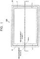
- FIG. 1 is a front view of one example of an embodiment of a laminated glass of the present invention
- FIG. 2 is a sectional view taken along a line X-X of the laminated glass illustrated in FIG. 1 .
- a laminated glass 10A illustrated in FIG. 1 and FIG. 2 includes a pair of glass plates 1A and 1B facing each other, and a pair of intermediate bonding layers 2A and 2B which are brought into contact with facing surfaces of the pair of glass plates 1A and 1B, respectively.
- the pair of glass plates 1A and 1B and the pair of intermediate bonding layers 2A and 2B have main surfaces with substantially the same shape and same dimensions.
- the laminated glass 10A further includes a functional film 3 having a main surface whose area is smaller than areas of the main surfaces of the glass plates 1A and 1B and having an outer periphery of the main surface located on the inside of the outer peripheries of the main surfaces of the glass plates 1A and 1B, at a position between the pair of intermediate bonding layers 2A and 2B.
- a thickness T1 measured at an end portion indicated by a measurement point E in FIG. 1 of the laminated glass 10A is smaller by 5 ⁇ m or more than a thickness T2 of the laminated glass 10A measured at a position indicated by a measurement point I in FIG. 1 on the inside by 10 mm from the end portion indicated by the measurement point E.
- the measurement of the thicknesses T1 and T2 is conducted by using an ordinary method, for example, a vernier caliper or a micrometer.
- the micrometer there can be cited a Digimatic straight line micrometer outside micrometer 406-250 OMV25M manufactured by Mitutoyo Corporation.
- the phenomenon in which the thickness becomes small at the end portion of the laminated glass is a phenomenon which is caused because, in a manufacturing step of the laminated glass 10A, deaeration is performed from a periphery of a laminate formed of glass plates 1A and 1B, intermediate bonding layers 2A and 2B, and a functional film 3, and then the laminate is subjected to a step of thermopressure bonding, so that a larger compressive force is applied to an end portion of the laminate, as will be described later.
- a force acts in directions in which the end portion expands to have a thickness same as a thickness on the inside (directions indicated by arrow marks in FIG. 2 ), due to a restoring force of the glass plates 1A and 1B.
- FIG. 2 the characteristic is illustrated with exaggeration when compared to an actual product, for the sake of explanation.
- the thickness of the laminated glass obtained through the manufacturing step as described above is almost uniformly small over the entire outer periphery of the laminated glass, at the end portion when compared to the inside. Therefore, in the laminated glass of the present invention, the measurement of the thickness is only required to be performed at two points including at least an arbitrary one point of the end portion, for example, the measurement point E in the laminated glass 10A and a position on the inside by 10 mm from the end portion, for example, the measurement point I in the laminated glass 10A, as exemplified in the laminated glass 10A.
- the arbitrary one point of the end portion may also be any one point on the outer periphery of the laminated glass.
- the position on the inside by 10 mm from the measurement point of the thickness of the end portion is, when the measurement point is located on one side in a linear shape of the outer periphery of the laminated glass, a position on the inside by 10 mm from the measurement point on a line which vertically intersects with the side at the measurement point.
- the above position is a position on the inside by 10 mm from the measurement point on a vertical line of a tangent of the measurement point.
- a position on the inside by 10 mm from the outer periphery of the laminated glass 10A is indicated by a frame line M.
- the laminated glass 10A when an arbitrary one point on the outer periphery is set to the measurement point E of the thickness of the end portion, one point on the frame line M satisfying the above relationship with respect to the measurement point E becomes the measurement point I positioned on the inside by 10 mm from the end portion.
- the effect of the present invention becomes further effective when the thickness measured at the end portion of the laminated glass is smaller by 10 ⁇ m or more, further 20 ⁇ m or more, and particularly 30 ⁇ m or more than the thickness of the laminated glass measured at the position on the inside by 10 mm from the end portion.
- substantially the same shape and same dimensions means having the same shape and the same dimensions as viewed by people and, for example, when two have “substantially the same shape and same dimensions", this also includes a case where one has an outer periphery shape not having unevenness such as a cutout and the other has an outer periphery shape having a minute cutout or the like on a part thereof, in the category thereof. Also in other cases, “substantially” indicates the same meaning as above.
- respective components which compose the laminated glass 10A will be described.
- the glass plates 1A and 1B used for the laminated glass 10A in the embodiment of the present invention there can be cited transparent inorganic glass and organic glass (resin).
- the inorganic glass ordinary soda lime glass (which is also referred to as soda lime silicate glass), borosilicate glass, non-alkali glass, quartz glass, and the like are used without any particular limitation.
- soda lime glass is particularly preferable.
- a forming method thereof is also not particularly limited and, for example, float plate glass formed by a float method or the like is preferable.
- the organic glass (resin) there can be cited a polycarbonate resin, a polystyrene resin, an aromatic polyester resin, an acrylic resin, a polyester resin, a polyarylate resin, a polycondensate of halogenated bisphenol A and ethylene glycol, an acrylic urethane resin, a halogenated aryl group-containing acrylic resin, and the like.
- the polycarbonate resin such as an aromatic polycarbonate resin and the acrylic resin such as a polymethyl methacrylate-based acrylic resin are preferable, and the polycarbonate resin is more preferable.
- a bisphenol A-based polycarbonate resin is particularly preferable.
- the glass plate may be composed by containing two or more kinds of the above resins.
- a colorless and transparent material with no coloring component added thereto may be used, or a colored and transparent material colored within the range not impairing the effect of the present invention may be used.
- one kind of the glass may be used or two or more kinds of the glass may be used in combination, and for example, a laminated substrate may be made by laminating two or more layers.
- the inorganic glass is preferable as the glass.
- the pair of glass plates 1A and 1B used for the laminated glass 10A may be made of mutually different kinds of materials, and they are preferably made of the same kind of material.
- a thickness of the each glass plate 1A and 1B can be appropriately selected according to the application place of the laminated glass 10A, and generally, the thickness is preferably 0.2 to 5 mm. In particular, when the thickness of the each glass plate 1A and 1B is 0.5 to 3 mm, a residual restoring force in the laminated glass acts significantly, so that the effect of the present invention can be obtained significantly in particular.
- the glass plates 1A and/or 1B may have a coating that imparts a water repellent function, a hydrophilic function, an antifogging function, low emissivity, ultraviolet absorption, and the like to an exposed surface exposed to the atmosphere.
- the facing surfaces facing each other of the glass plates 1A and/or 1B may have functional coatings such as an infrared cut coating, and a conductive coating.
- the following intermediate bonding layers 2A and 2B are configured to be brought into contact with the functional coatings on the facing surfaces of the glass plates 1A and 1B.
- a black ceramic layer is provided mainly on peripheral edge portion of the glass plate 1A or 1B.
- the black ceramic layer can be formed by using a publicly-known material such as a colored ceramic paste.
- ink to be used for forming the black ceramic layer for example, there is used ink made by dispersing a deep-colored pigment, a glass frit, a refractory filler, and a resin such as ethyl cellulose in a solvent.
- ink made by dispersing a deep-colored pigment, a glass frit, a refractory filler, and a resin such as ethyl cellulose in a solvent.
- the pair of intermediate bonding layers 2A and 2B in the laminated glass 10A have main surfaces with substantially the same shape and same dimensions as those of the main surfaces of the glass plates 1A and 1B.
- the intermediate bonding layers 2A and 2B are provided to be brought into contact with the facing surfaces of the glass plates 1A and 1B, respectively, while sandwiching the functional film 3 therebetween.
- the intermediate bonding layers 2A and 2B have a function of bonding the functional film 3 so as to sandwich it between the pair of glass plates 1A and 1B via the intermediate bonding layers 2A and 2B to integrate them as the laminated glass 10A.
- At least one of the intermediate bonding layers 2A and 2B has the moisture permeability (A).
- the moisture permeability (A) indicates that the degree of moisture permeability at a temperature of 40°C and a humidity of 90% RH measured according to JIS Z0208: 1976 is 50 g/m 2 ⁇ day or less.
- the moisture permeability of the intermediate bonding layer is, as the degree of moisture permeability measured similarly to the moisture permeability (A), preferably 30 g/m 2 ⁇ day or less, more preferably 15 g/m 2 ⁇ day or less, and still more preferably 10 g/m 2 ⁇ day or less. It is more preferable that both of the intermediate bonding layers 2A and 2B have the moisture permeability (A).
- At least one of the intermediate bonding layers 2A and 2B preferably has the adhesiveness (B).
- the adhesiveness (B) indicates that an adhesive force with respect to a polyester film is 30 N/25 mm or more, which is measured according to JIS K 6854-2: 1999, under conditions where a width of a test piece is 25 mm, a testing rate is 300 mm per minute, and a peel angle is 180 degrees.
- the adhesiveness of the intermediate bonding layer is, as the adhesive force measured similarly to the adhesiveness (B), more preferably 60 N/25 mm or more, and still more preferably 80 N/25 mm or more.
- the adhesiveness is preferably 150 N/25 mm or less, as the adhesive force measured similarly to the adhesiveness (B).
- the functional film 3 sandwiched by the intermediate bonding layers 2A and 2B sometimes has a polyester film on one surface or both surfaces, like a functional film made by performing functional coating on one main surface of the polyester film or a functional film made by sandwiching a functional membrane between a pair of the polyester films, for example.
- a polyester film there can be cited, for example, polyethylene terephthalate, polybutylene terephthalate, polyethylene naphthalate, polybutylene naphthalate, or the like.
- the adhesive force acts between the intermediate bonding layers 2A and 2B, and the functional film 3 so as to be against the restoring force of the glass plates 1A and 1B acting at the end portion of the laminated glass described above, which enables to suppress the peeling of the end portion of the laminated glass.
- the intermediate bonding layer preferably further has an adhesiveness with other members of the laminated glass, for example, adhesiveness (C) indicating that an adhesive force with respect to a glass plate is not less than 40 N/25 mm nor more than 150 N/25 mm which is measured according to JIS K 6854-2: 1999, under conditions where a test piece width is 25 mm, a testing rate is 300 mm per minute, and a peel angle is 180 degrees, or adhesiveness (D) indicating that an adhesive force with respect to a black ceramic layer of a glass plate with the black ceramic layer is not less than 20 N/25 mm nor more than 150 N/25 mm which is measured according to JIS K 6854-2: 1999, under conditions where a test piece width is 25 mm, a testing rate is 300 mm per minute, and a peel angle is 180 degrees.
- adhesiveness (C) indicating that an adhesive force with respect to a glass plate is not less than 40 N/25 mm nor more than 150 N/25 mm which is measured according to JIS K
- thermoplastic resins as a main component into sheets having main surfaces with substantially the same shape and same dimensions as those of the main surfaces of the glass plates 1A and IB.
- thermoplastic resin is not particularly limited as long as it can be integrated when a composition containing it as a main component is formed into sheets and used as the pair of intermediate bonding layers 2A and 2B to sandwich the functional film 3, then inserted in between the pair of glass plates 1A and 1B, and heated and pressurized to form the laminated glass 10A.
- a transmittance of the intermediate bonding layer is preferably one capable of achieving 80% or more of visible light transmittance in a state where a laminated glass is formed by combining the intermediate bonding layers with normal colorless and transparent glass.
- thermoplastic resins which are conventionally used as intermediate bonding layers, such as a polyvinyl acetal resin such as a polyvinyl butyral resin (PVB), a polyvinyl chloride resin, a saturated polyester resin, a polyurethane resin, an ethylene-vinyl acetate copolymer resin (EVA), an ethylene-ethyl acrylate copolymer resin, and a polyolefin based copolymer.
- PVB polyvinyl butyral resin
- EVA ethylene-vinyl acetate copolymer resin
- EVA ethylene-ethyl acrylate copolymer resin
- polyolefin based copolymer a polyolefin based copolymer
- thermoplastic resin for the intermediate bonding layer of the laminated glass is selected according to usage and in consideration of balance among various properties such as transparency, weather resistance, strength, adhesive force, penetration resistance, impact energy absorbency, moisture resistance, heat insulating property, and sound insulating property. From a viewpoint of these conditions, a resin composition in which a vinyl acetate unit in an ethylene-vinyl acetate copolymer is saponified, an ethylene-vinyl acetate copolymer resin composition as described in JP-B No. 5625781 , characterized in that organized layered clay, a silane coupling agent, and the like are contained in an ethylene-vinyl acetate copolymer, and so on are preferable among the above-described thermoplastic resins.
- Containing the organized layered clay makes it possible to significantly reduce the moisture permeability as compared to an ordinary ethylene-vinyl acetate copolymer resin composition. Further, a resin composition containing a modified block copolymer hydride described in JP-A No. 2015-821 can also be preferably used.
- the thermoplastic resin preferably contains no plasticizer, or when the thermoplastic resin contains the plasticizer, it is preferable that the thermoplastic resin contains the plasticizer which does not affect the functional film.
- thermoplastic resin for the intermediate bonding layer if the heating temperature is equal to or more than a heatproof temperature of the functional film, there is a case where the functional film does not sufficiently function when it is made into the laminated glass. From this point, it is preferable to select the thermoplastic resin for the intermediate bonding layer so that the laminated glass forming temperature becomes equal to or less than the heatproof temperature of the functional film to be used.
- thermoplastic resin-containing composition containing the above-described thermoplastic resin as a main component is used.
- the thermoplastic resin-containing composition may contain one kind or two or more kinds of various additives such as, for example, an infrared absorbent, an ultraviolet absorbent, a fluorescer, an adhesion regulator, a coupling agent, a surfactant, an antioxidant, a heat stabilizer, a light stabilizer, a dehydrating agent, a defoaming agent, an antistatic agent, and a flame retarder within the range not impairing the effect of the present invention and according to various purposes.
- additives are entirely and uniformly contained in the intermediate bonding layers 2A and 2B.
- a film thickness of the intermediate bonding layers 2A and 2B is not particularly limited.
- the film thickness of one layer is preferably 0.05 to 0.8 mm, and the total film thickness of two layers is preferably 0.1 mm or more, similarly to the intermediate bonding layers which are normally used for the laminated glass and the like. If the film thickness of one layer of the intermediate bonding layers is less than 0.05 mm or the total film thickness of two layers is less than 0.1 mm, strength sometimes becomes insufficient, and if there is a large glass mismatch, peeling becomes likely to occur.
- the total film thickness of the intermediate bonding layers 2A and 2B becomes 0.7 mm or more and further, when it becomes 0.8 mm or more, it is possible to particularly effectively suppress swelling of the intermediate bonding layers caused by intrusion of moisture from the end portion, and thus it is possible to particularly significantly achieve the effect of the present invention.
- Each of the intermediate bonding layers 2A and 2B is not limited to a single-layer structure.
- the intermediate bonding layers 2A and 2B may be the same and do not need to be the same, and each of them can independently select a single-layer structure or a multilayer structure.
- the functional film 3 there can be cited a light-control film, an infrared reflection film, a screen film for image projection, a thin solar cell film for power generation, a self-luminous film, and the like.
- the functional film may have a configuration in which coating is performed on a film such as, for example, a polyester film, or a configuration in which a material having functions of reflection of light, light scattering, power generation, light emission and the like is sandwiched between two or more of films, for example, polyester films.
- the functional film one kind or two or more kinds thereof are used.
- the functional films it is preferable to combine and use the functional films with different functions such as later-described light-control film and infrared reflection film, for example.
- the laminated glass of the present invention includes the functional film which includes at least one kind selected from the light-control film and the infrared reflection film, it is possible to effectively suppress the deterioration of the functional film due to the intrusion of moisture and the like from the end portion, in particular.
- a thickness of the functional film 3 is preferably 25 to 500 ⁇ m from a viewpoint of handleability and deaeration treatment in a laminated glass manufacturing step. At this time, if the thickness of the functional film is 25 to 120 ⁇ m, a barrier layer provided so as to surround the functional film in the laminated glass may be unnecessary as will be described later, and when the thickness of the functional film becomes 120 to 500 ⁇ m, the later-described barrier layer is preferably provided.
- the thickness of the functional film 3 becomes 200 ⁇ m or more, and further, when it becomes 300 ⁇ m or more, it is possible to particularly effectively suppress the deterioration of the functional film caused by the intrusion of moisture and the like from the end portion, and thus it is possible to particularly significantly achieve the effect of the present invention.
- a light-control film being the functional film 3 (hereinafter, the light-control film is also denoted by a reference numeral 3) has a main surface having an area smaller than and substantially the similar shape as those of the main surfaces of the glass plates 1A and 1B, and is arranged between the intermediate bonding layers 2A and 2B so that the outer periphery of the main surface is positioned on the inside of the outer peripheries of the main surfaces of the glass plates 1A and 1B.
- the main surfaces of the glass plates 1A and 1B are rectangular.
- the main surface shape of the light-control film 3 is a shape made by cutting all of peripheries of end portions at four sides into band shapes with respect to the main surface shapes of the glass plates 1A and 1B, in other words, into a frame shape, and the intermediate bonding layers 2A and 2B or a later-described barrier layer 4 illustrated in FIG. 3 are/is provided in a manner to compensate for the cut portion.
- the main surface shape of the light-control film 3 may be a shape made by cutting a part of the peripheral edge portions, for example, only a peripheral edge portion at any one side of the four sides into a band shape with respect to the main surface shapes of the glass plates 1A and 1B, a shape made by cutting peripheral edge portions at any two sides, or a shape made by cutting peripheral edge portions at any three sides.
- the intermediate bonding layers 2A and 2B or the barrier layer 4 are/is only required to be arranged according to the cut shape of the light-control film 3 in a manner to compensate for the cut portion.
- a width w of the cut portion of the light-control film 3 can be appropriately selected according to the usage.
- the laminated glass of the present invention is configured to be able to suppress the peeling between the intermediate bonding layer and the light-control film, so that the width w of the cut portion of the light-control film 3 may be 40 mm or less, and may be preferably 20 mm or less.
- the light-control film 3 preferably has the cut portion.
- the width w of the cut portion of the light-control film 3 is preferably greater than 0 mm and equal to or less than 40 mm.
- the light-control film 3 it is possible to use a suspended particle device (SPD) film, a light-control film using a liquid crystal element, an electrochromic light-control film, or the like.
- SPD film a general SPD film is usable that is configured to sandwich a polymer layer containing suspended particles that can be oriented by application of voltage thereto between two electrically insulating films having insides coated with transparent conducting films.
- a commercial product can be used. Incidentally, such a commercial product is supplied in a predetermined size, so that it is cut, when used, into a desired size according to the size of the laminated glass.
- a thickness of the SPD film used for the laminated glass 10A is not particularly limited, and it is preferably 200 to 400 ⁇ m from the viewpoint of handleability and easiness of availability.
- a liquid crystal light-control element disclosed in JP-A No. 2005-17860 , made by sandwiching a liquid crystalline mixture containing a non-polymerizable liquid crystal composition and a polymerizable compound between a pair of transparent resin substrates with electrodes at a temperature at which the liquid crystalline mixture has a predetermined or more of viscosity and shows a liquid crystal phase, and one made by arranging a liquid crystal composition containing a polymerizable compound which is polymerized by ultraviolet rays, between a pair of transparent resin substrates with electrodes.
- the laminated glass having the light-control film sealed therein is mounted on a vehicle such as an automobile or a railway vehicle, an airplane, or the like, if a power source mounted on the inside the vehicle, the airplane, or the like is cut off, the laminated glass stops driving in its opaque state, which may cause a safety problem.
- FIG. 3 illustrates a sectional view of one example of the laminated glass of the present invention provided with a barrier layer.
- a laminated glass 10B illustrated in FIG. 3 includes a pair of glass plates 1A and 1B facing each other, a pair of intermediate bonding layers 2A and 2B which are brought into contact with facing surfaces of the pair of glass plates 1A and 1B, respectively, and a functional film, for example, a light-control film 3 arranged so as to be sandwiched by the intermediate bonding layers 2A and 2B.
- the pair of glass plates 1A and 1B and the pair of intermediate bonding layers 2A and 2B have main surfaces with substantially the same shape and same dimensions
- a main surface of the light-control film 3 has a size such that an outer periphery of the main surface is entirely positioned on the inside by a width w relative to the outer peripheries of the glass plates 1A and 1B
- a barrier layer 4 whose main surface has a frame shape with the width w is provided on the outside of the light-control film 3 in a manner that it is brought into contact with an end face of the light-control film 3 and it is sandwiched by the intermediate bonding layers 2A and 2B.
- the configuration other than the barrier layer 4 is similar to the configuration of the laminated glass 10A.
- the barrier layer 4 is, for example, previously formed in the frame shape so as to surround the periphery of the light-control film 3 to be laminated at the time of manufacturing the laminated glass 10B, and it preferably has the moisture permeability (A).
- the moisture permeability (A) is as described above.
- the moisture permeability of the barrier layer 4 is, as the moisture permeability measured similarly to the moisture permeability (A), more preferably 30 g/m 2 ⁇ day or less, furthermore preferably 15 g/m 2 ⁇ day or less, and still more preferably 10 g/m 2 ⁇ day or less.
- a material of forming the barrier layer 4 a material similar to the material of the aforementioned intermediate bonding layer can be used.
- the laminated glasses 10A and 10B each having the light-control film 3 as the functional film it is possible that another functional film other than the light-control film 3, normally, a functional film whose function is different from that of the light-control film 3, is provided between the pair of glass plates 1A and 1B.
- another functional film for example, an intermediate bonding layer is further provided in addition to the above-described pair of intermediate bonding layers 2A and 2B, and the laminated glass may be configured by laminating the glass plate, the intermediate bonding layer, the another functional film, the intermediate bonding layer, the light-control film, the intermediate bonding layer, and the glass plate in this order.
- This laminated constitution can be applied in common in cases where two types of functional films are used.
- the functional films are designed to have main surfaces whose outer peripheries are located on the inside of the outer peripheries of the glass plates, and the barrier layers are provided so as to surround the peripheries of the functional films.
- an infrared reflection film As the another functional film in the laminated glasses 10A and 10B each having the light-control film 3 as the functional film, there can be cited an infrared reflection film and so on, for example.
- the infrared reflection film concretely, there can be cited one in which a conventionally well-known infrared reflection film such as an infrared reflection film having a film thickness of about 100 to 500 nm and including a dielectric multilayer film, a liquid crystal alignment film, an infrared reflector-containing coating film, and a single-layer or multilayer infrared reflective film including a metal film is formed as an infrared reflection film on a supporting film such as a PET (polyethylene terephthalate) film having a thickness of about 25 to 200 ⁇ m or the like.
- a dielectric multilayer film made by laminating resin films with different refractive indices and having a total film thickness of about 25 to 200 ⁇ m, and so on can be further cited.
- the laminated glass according to the embodiment may have a configuration having three or more glass plates according to need in which, for example, one or more glass plates are laminated on the atmosphere side of the glass plate 1A or the glass plate 1B of the laminated glasses 10A or 10B each via an intermediate bonding layer prepared separately from the intermediate bonding layers 2A and 2B. Further, the laminated glass according to the embodiment may optionally have another layer within the range not impairing the effect of the present invention, in addition to the above-described components.
- a black ceramic layer is sometimes provided, as another layer, in a band shape at a part or all of the peripheral edge portion of the main surface, on a side where it is brought into contact with the intermediate bonding layer, of at least one of the glass plates out of the pair of glass plates composing the laminated glass, for the purpose of hiding a portion attached to a frame body or the like, the wiring conductor, and so on and for the purpose of preventing appearance deterioration as a result of deterioration over time of the end portion of the functional film such as the light-control film due to moisture from the outside.
- a black ceramic layer may be provided as another layer.
- a width of the black ceramic layer is narrow, which is concretely 30 mm or less, further 25 mm or less, and particularly 20 mm or less, the effect of the present invention can be obtained significantly in particular.
- the laminated glass according to the embodiment of the present invention can be manufactured by a generally used publicly-known technique.
- a laminate in which the functional film, for example, the light-control film 3 is arranged to be located in a predetermined positional relationship between the pair of intermediate bonding layers 2A and 2B is produced, and the laminate is inserted in between the pair of glass plates 1A and 1B to prepare a laminated glass precursor being laminated glass before pressure bonding in which the glass plate 1A, the intermediate bonding layer 2A, the functional film (light-control film) 3, the intermediate bonding layer 2B, and the glass plate 1B are laminated in this order.
- glass plates and respective layers are laminated in the similar lamination order to that of similarly obtained laminated glass to prepare a laminated glass precursor.
- the laminated glass may also be manufactured through the following method. Specifically, in the laminated glass 10B, a laminate in which the functional film, for example, the light-control film 3 and the barrier layer 4 are arranged to be located in a predetermined positional relationship between the pair of intermediate bonding layers 2A and 2B is produced, and the laminate is inserted in between the pair of glass plates 1A and 1B to prepare a laminated glass precursor being laminated glass before pressure bonding in which the glass plate 1A, the intermediate bonding layer 2A, the layer composed of the functional film (light-control film) 3 and the barrier layer 4, the intermediate bonding layer 2B, and the glass plate 1B are laminated in this order.
- the functional film for example, the light-control film 3 and the barrier layer 4
- This laminated glass precursor is put in a vacuum bag such as a rubber bag, the vacuum bag is connected to an exhaust system, bonding is performed at a temperature of about 70 to 110°C while performing pressure-reduction suction (deaeration) so that a pressure in the vacuum bag becomes a pressure reduction degree of about -65 to -100 kPa, and thereby the laminated glass according to the embodiment can be obtained. Further, for example, by making the laminated glass precursor after above bonding treatment to be subjected to pressure bonding treatment of heating and pressurizing it under conditions of 100 to 110°C and a pressure of 0.6 to 1.3 MPa, it is possible to obtain laminated glass having further excellent durability.
- the laminated glass of the present invention suppresses deterioration over time of the functional property, particularly peeling of the functional film and the intermediate bonding layer caused by swelling of the intermediate bonding layer which is caused by intrusion of moisture from the end portion, resulting in that it is possible to obtain a laminated glass with no problems in appearance for a long term.
- the laminated glass of the present invention is suitably used for window glass for vehicle, for example.
- An evaluation sample having a configuration similar to that of the laminated glass 10B illustrated in FIG. 3 was produced in the following manner. Hereinafter, explanation will be made by giving reference numerals same as those in the laminated glass 10B to respective members of the evaluation sample corresponding to the respective members of the laminated glass 10B.
- Glass plates 1A and 1B (2 mm thickness, 150 mm ⁇ 150 mm size) made of two pieces of soda lime glass, two saponified EVA intermediate bonding layers 2A and 2B (manufactured by TOSOH NIKKEMI CORPORATION, Melthene G7055 (product name), 0.4 mm thickness, 150 mm ⁇ 150 mm size), one SPD light-control film 3 (manufactured by Hitachi Chemical Co., Ltd., LCF-1103DHA90 (product name), 0.35 mm thickness, 130 mm ⁇ 130 mm size, with both surfaces composed of polyester films), a barrier layer 4 (manufactured by TOSOH NIKKEMI CORPORATION, Melthene G7055 (product name), 0.4 mm thickness, 150 mm ⁇ 150 mm size in which a center portion thereof was hollowed out so that an edge had a frame shape with a width w of 10 mm), were prepared.
- the laminate obtained in the above was put in a vacuum packaging made of rubber to be subjected to deaeration, then put into an oven kept at 100°C and let stand for 60 minutes, and subjected to pressure bonding, to thereby obtain the evaluation sample.
- the measurement point E was set to a center portion of one side of an outer periphery of the laminated glass, and the measurement point I was set to a position on the inside by 10 mm from the measurement point E toward the center of the laminated glass.
- a result thereof was described in Table 1 as the thickness difference.
- the moisture permeability of the aforementioned intermediate bonding layer was measured by the above-described method similar to the method for the moisture permeability (A) according to JIS Z 0208: 1976, and a result thereof was 14 [g/m 2 ⁇ day].
- the adhesive force between the aforementioned intermediate bonding layer (Melthene G7055) and the polyester film was measured by the above-described method similar to the method for the adhesiveness (B) according to JIS K 6854-2: 1999, and a result thereof was 86.0 [N/25 mm].
- the sample for measuring the adhesiveness with respect to the polyester film was produced in the following manner.
- a polyester film (manufactured by Toyobo Co., Ltd, product name COSMOSHINE A4100, 100 mm thickness ⁇ 60 mm ⁇ 25 mm size) and the aforementioned intermediate bonding layer were laminated in this order, and this laminate was put in a vacuum bag made of plastic. After that, it was subjected to pressure bonding at 110°C while performing deaeration under reduced pressure so that a pressure reduction degree became -60 kPa or less.
- the evaluation sample obtained in the above was put in a thermohygrostat at 80°C and a humidity of 95% RH for 1000 hours.
- a thickness of one point (measurement point E) of the above-described end portion of the evaluation sample was measured before and after the evaluation sample was put in the thermohygrostat (the thickness before the evaluation sample was put in the thermohygrostat was set to T1 before , and the thickness after the evaluation sample was put in the thermohygrostat was set to T1 after ) by using a vernier caliper, and "thickness change rate (%)" was calculated through (T1 after - T1 before ) / T1 before ⁇ 100 [%]. Further, the presence or absence of peeling of the evaluation sample was evaluated visually. Results thereof are shown in Table 1.
- An evaluation sample for experiment was produced similarly to the evaluation sample of the above-described example 1 except that the SPD light-control film 3 was changed in shape (110 mm ⁇ 110 mm size) while using the same material, and the barrier layer 4 was changed in shape (a center portion thereof with a size of 1 50 mm ⁇ 150 mm was hollowed out so that an edge had a frame shape with a width w of 20 mm) while using the same material, and the moisture-proof property evaluation similar to the above was performed.
- the measurement results are shown in Table 1.
- An evaluation sample for experiment was produced similarly to the evaluation sample of the above-described example 1 except that the SPD light-control film 3 was changed in shape (70 mm ⁇ 70 mm size) while using the same material, and the barrier layer 4 was changed in shape (a center portion thereof with a size of 150 mm ⁇ 150 mm was hollowed out so that an edge had a frame shape with a width w of 40 mm) while using the same material, and the moisture-proof property evaluation similar to the above was performed.
- the measurement results are shown in Table 1.
- An evaluation sample for experiment was produced similarly to the evaluation sample of the above-described example 1 except that each of the intermediate bonding layers 2A and 2B, and the barrier layer 4 was changed to another EVA intermediate bonding layer (manufactured by TOSOH NIKKEMI CORPORATION, Melthene G7060 (product name)) while having the same shape and the same size, and the moisture-proof property evaluation similar to the above was performed.
- the measurement results are shown in Table 1. Note that when the moisture permeability and the adhesive force of Melthene G7060 were measured similarly to the above-described example 1, the moisture permeability was 53 [g/m 2 ⁇ day], and the adhesive force was 28.1 [N/25 mm].
- An evaluation sample for experiment was produced similarly to the evaluation sample of the above-described example 2 except that each of the intermediate bonding layers 2A and 2B, and the barrier layer 4 was changed to one using another material (manufactured by TOSOH NIKKEMI CORPORATION, Melthene G7060 (product name)) while having the same shape and the same size, and the moisture-proof property evaluation similar to the above was performed.
- the measurement results are shown in Table 1.
- Example 1 Example 2
- Example 3 Comparative example 1 Comparative example 2
- Reference example Material of intermediate bonding layer and barrier layer Product name Melthene G7055 Melthene G7060 Melthene G7055 Degree of moisture permeability according to measuring method of moisture permeability (A) [g/m 2 ⁇ day] 14 53 14
- Adhesive force according to measuring method of adhesiveness (B) [N/25 mm] 86 28.1 86 Frame width w of barrier layer 4 [mm] 10 20 40 10 i 20 20 20
- Thickness difference (T2 - T1) [ ⁇ m] 103 86 59 119 93
- 10A, 10B ... laminated glass, 1A and 1B ... glass plate, 2A and 2B ... intermediate bonding layer, 3 ... functional film (light-control film), 4 ... barrier layer
Landscapes
- Joining Of Glass To Other Materials (AREA)
- Laminated Bodies (AREA)
Claims (8)
- Laminiertes Glas, umfassend:ein Paar von Glasplatten, aneinander zugewandt,ein Paar von Zwischenbindungsschichten, in Kontakt mit gegenüberliegenden Oberflächen des Paars von Glasplatten gebracht, worin mindestens eine von diesen die folgende Feuchtigkeitspermeabilität (A) aufweist; undeinen funktionalen Film, angeordnet zwischen dem Paar von Zwischenbindungsschichten, wobei eine Dicke, gemessen an einem Endabschnitt des laminierten Glases, um 5 µm oder mehr geringer ist als eine Dicke des laminierten Glases, gemessen an einer Position auf der Innenseite um 10 mm von dem Endabschitt,wobei die Feuchtigkeitspermeabilität (A) anzeigt, dass ein Maß der Feuchtigkeitspermeabilität bei einer Temperatur von 40°C und einer Feuchtigkeit von 90% relativer Luftfeuchtigkeit gemessen gemäß JIS Z 0208:1976 50 g/m2 · Tag oder weniger beträgt,wobei die Dicke an einem Endabschnitt des laminierten Glases während des Herstellungsschritt des laminierten Glases durch Durchführen eines Entlüftungsschritts von einer Peripherie des Glaslaminats und Unterwerfen des Glaslaminats einem Schritt des Thermodruckbindens, so dass eine größere Kompressionskraft an einem Endabschnitt des Glaslaminats angelegt wird, erhalten wird.
- Laminiertes Glas gemäß Anspruch 1, wobei der funktionale Film einen Polyesterfilm auf einer Oberfläche aufweist, und mindestens eine der Zwischenbindungsschichten, in Kontakt mit dem Polyesterfilm gebracht, das folgende Haftvermögen (B) zeigt,
wobei das Haftvermögen (B) anzeigt, dass eine Haftkraft bezüglich eines Polyesterfilms 30 N/25 mm oder mehr beträgt, welche gemäß JIS K 6864-2:1999 gemessen wird, unter Bedingungen, bei welchen eine Breite eines Teststücks 25 mm ist, eine Testgeschwindigkeit 300 mm pro Minute ist und ein Abschälwinkel 180 Grad ist. - Laminiertes Glas gemäß Anspruch 1 oder 2, wobei ein Endabschnitt des funktionalen Films auf der Innenseite um mehr als 0 mm und gleich zu oder weniger als 40 mm relativ zu Endabschnitten des Paars von Glasplatten positioniert ist.
- Laminiertes Glas gemäß einem der Ansprüche 1 bis 3, wobei eine Dicke des funktionalen Films 200 µm oder mehr beträgt.
- Laminiertes Glas gemäß einem der Ansprüche 1 bis 4, wobei eine Gesamtdicke der Zwischenbindungsschicht 0,7 mm oder mehr beträgt.
- Laminiertes Glas gemäß einem der Ansprüche 1 bis 5, weiter umfassend eine schwarze Keramikschicht mit einer Breite von 30 mm oder weniger an einem peripheren Kantenabschnitt einer Hauptoberfläche, auf einer Seite, welche in Kontakt mit der Zwischenbindungsschicht, von mindestens einer der Glasplatten aus dem Paar von Glasplatten, gebracht ist.
- Laminiertes Glas gemäß einem der Ansprüche 1 bis 6, wobei das laminierte Glas eine Vielzahl der funktionalen Filme mit unterschiedlichen Funktionen umfaßt, an einer Position zwischen dem Paar von Glasplatten und dem Paar von Zwischenbindungsschichten.
- Laminiertes Glas gemäß einem der Ansprüche 1 bis 7, wobei der funktionale Film mindestens einen, ausgewählt aus der Gruppe, bestehend aus einem Lichtkontrollfilm und einem Infrarotreflexionsfilm, einschließt.
Applications Claiming Priority (2)
| Application Number | Priority Date | Filing Date | Title |
|---|---|---|---|
| JP2015239985 | 2015-12-09 | ||
| PCT/JP2016/086511 WO2017099167A1 (ja) | 2015-12-09 | 2016-12-08 | 合わせガラス |
Publications (3)
| Publication Number | Publication Date |
|---|---|
| EP3388403A1 EP3388403A1 (de) | 2018-10-17 |
| EP3388403A4 EP3388403A4 (de) | 2020-09-23 |
| EP3388403B1 true EP3388403B1 (de) | 2020-12-02 |
Family
ID=59014228
Family Applications (1)
| Application Number | Title | Priority Date | Filing Date |
|---|---|---|---|
| EP16873060.4A Active EP3388403B1 (de) | 2015-12-09 | 2016-12-08 | Verbundglas |
Country Status (5)
| Country | Link |
|---|---|
| US (1) | US10870262B2 (de) |
| EP (1) | EP3388403B1 (de) |
| JP (1) | JP7024408B2 (de) |
| CN (1) | CN108367980A (de) |
| WO (1) | WO2017099167A1 (de) |
Families Citing this family (24)
| Publication number | Priority date | Publication date | Assignee | Title |
|---|---|---|---|---|
| WO2019004160A1 (ja) * | 2017-06-26 | 2019-01-03 | 大日本印刷株式会社 | 調光部材、サンバイザ及び移動体 |
| KR20240064046A (ko) * | 2017-07-31 | 2024-05-10 | 다이니폰 인사츠 가부시키가이샤 | 접합 유리, 접합 유리의 제조 방법 |
| JP7147139B2 (ja) * | 2017-07-31 | 2022-10-05 | 大日本印刷株式会社 | 合わせガラスの製造方法 |
| JP7054468B2 (ja) * | 2017-09-26 | 2022-04-14 | 大日本印刷株式会社 | 調光セル、および調光パネル |
| CO2018000469A1 (es) * | 2017-11-30 | 2018-04-30 | Agp America Sa | Laminado automotriz con capa de compensación de sustrato de borde sólido invisible |
| TWI822743B (zh) * | 2018-03-28 | 2023-11-21 | 日商日東電工股份有限公司 | 含玻璃薄膜之調光元件 |
| US10981358B2 (en) * | 2018-04-03 | 2021-04-20 | AGC Inc. | Laminated glass |
| JP6887618B2 (ja) * | 2018-05-30 | 2021-06-16 | 日本電気硝子株式会社 | 調光機能付き積層体 |
| JP6669214B2 (ja) * | 2018-08-27 | 2020-03-18 | 凸版印刷株式会社 | 調光装置、および、調光装置の製造方法 |
| EP3892598A4 (de) | 2018-12-05 | 2022-08-17 | Nippon Sheet Glass Company, Limited | Verbundscheibe für kraftfahrzeuge |
| CN114571810A (zh) * | 2019-02-20 | 2022-06-03 | Agc株式会社 | 夹层玻璃 |
| CN113518711A (zh) * | 2019-03-04 | 2021-10-19 | Agc株式会社 | 夹层玻璃 |
| JP7451898B2 (ja) * | 2019-08-01 | 2024-03-19 | 大日本印刷株式会社 | 調光装置、調光装置用積層体及び調光セル |
| JP7363547B2 (ja) * | 2020-02-06 | 2023-10-18 | Agc株式会社 | 合わせガラス |
| CN115315648B (zh) * | 2020-03-27 | 2026-04-10 | 日东电工株式会社 | 光学构件、以及使用了该光学构件的背光灯单元及图像显示装置 |
| JP7722358B2 (ja) * | 2020-04-03 | 2025-08-13 | Agc株式会社 | 合わせガラス |
| CN112768551A (zh) * | 2020-04-30 | 2021-05-07 | 法国圣戈班玻璃公司 | 层叠结构组件、窗组件和控制方法 |
| CN115917108A (zh) * | 2020-08-21 | 2023-04-04 | Agc株式会社 | 夹层玻璃和夹层玻璃的制造方法 |
| JPWO2022075015A1 (de) * | 2020-10-05 | 2022-04-14 | ||
| JP2022121415A (ja) * | 2021-02-08 | 2022-08-19 | Agc株式会社 | 車両用合わせガラス |
| WO2022186338A1 (ja) * | 2021-03-04 | 2022-09-09 | Agc株式会社 | 合わせガラス、及び合わせガラスの製造方法 |
| DE112022004258T5 (de) * | 2021-09-01 | 2024-06-20 | AGC Inc. | Fahrzeugverbundglas und fahrzeugfensterkonstruktion |
| CN118984817A (zh) * | 2022-04-05 | 2024-11-19 | Agc株式会社 | 车辆用夹层玻璃 |
| CN115182669B (zh) * | 2022-07-22 | 2023-12-08 | 福耀玻璃工业集团股份有限公司 | 调光玻璃、车门总成及车辆 |
Family Cites Families (27)
| Publication number | Priority date | Publication date | Assignee | Title |
|---|---|---|---|---|
| JPS5384681A (en) | 1976-12-29 | 1978-07-26 | Mitsumi Electric Co Ltd | Method of producing leadless package |
| JPS54112386A (en) | 1978-02-22 | 1979-09-03 | Nippon Kougiyou Senjiyou Kk | Cleaning method for copperrcontaining scale |
| JP3095500B2 (ja) * | 1991-12-27 | 2000-10-03 | 三井化学株式会社 | 合わせガラス |
| JPH05286742A (ja) | 1992-04-07 | 1993-11-02 | Nippon Sheet Glass Co Ltd | 合せガラスの接着方法 |
| FR2827396B1 (fr) * | 2001-07-12 | 2003-11-14 | Saint Gobain | Dispositif electrocommandable a proprietes optiques et/ou energetiques variables |
| US7122242B2 (en) * | 2002-04-05 | 2006-10-17 | Ppg Industries Ohio, Inc. | Wedge shaped glass and methods of forming wedged glass |
| JP2005017860A (ja) | 2003-06-27 | 2005-01-20 | Asahi Glass Co Ltd | 液晶調光素子の製造方法 |
| DE102004018170B4 (de) * | 2004-04-14 | 2009-04-02 | Saint-Gobain Sekurit Deutschland Gmbh & Co. Kg | Verfahren zum Herstellen einer Verbundscheibe mit einem mehrschichtigen Folienlaminat |
| JP2007106659A (ja) * | 2005-10-17 | 2007-04-26 | Nippon Sheet Glass Co Ltd | 合わせガラス、その製造方法及び合わせガラス用中間膜 |
| GB0607745D0 (en) * | 2006-04-20 | 2006-05-31 | Pilkington Plc | Glazing |
| GB0712826D0 (en) * | 2007-07-03 | 2007-08-08 | Pilkington Group Ltd | RF interference reduction for functional glazings |
| JP5344116B2 (ja) * | 2008-01-09 | 2013-11-20 | セントラル硝子株式会社 | プラスチックフィルム挿入合せガラス |
| JP4992807B2 (ja) * | 2008-04-15 | 2012-08-08 | セントラル硝子株式会社 | 合わせガラスの製造方法および合わせガラス |
| GB0811058D0 (en) | 2008-06-17 | 2008-07-23 | Pilkington Group Ltd | Sealed switchable glazing |
| GB0910295D0 (en) * | 2009-06-16 | 2009-07-29 | Pilkington Group Ltd | Laminated structure |
| GB0916379D0 (en) * | 2009-09-18 | 2009-10-28 | Pilkington Group Ltd | Laminated glazing |
| CN102725143B (zh) | 2010-01-25 | 2015-09-30 | 旭硝子株式会社 | 层叠体的制造方法以及层叠体 |
| JP5625781B2 (ja) | 2010-11-12 | 2014-11-19 | 東ソー株式会社 | エチレン−酢酸ビニル共重合体樹脂組成物、それからなる合わせガラス用中間膜及びそれを用いた合わせガラス |
| DE102011085034A1 (de) * | 2011-10-21 | 2013-04-25 | Tesa Se | Klebemasse insbesondere zur Kapselung einer elektronischen Anordnung |
| BE1020717A3 (fr) * | 2012-06-19 | 2014-04-01 | Agc Glass Europe | Toit de vehicule. |
| WO2014122704A1 (ja) * | 2013-02-05 | 2014-08-14 | 日本板硝子株式会社 | 合わせガラス |
| JP6144335B2 (ja) * | 2013-04-19 | 2017-06-07 | 本田技研工業株式会社 | 調光パネル構造体 |
| JP6065221B2 (ja) | 2013-06-13 | 2017-01-25 | 日本ゼオン株式会社 | 合わせガラス板 |
| JP6127805B2 (ja) * | 2013-07-24 | 2017-05-17 | 旭硝子株式会社 | 車両用合わせガラスおよびその製造方法 |
| CN105555567A (zh) * | 2013-09-18 | 2016-05-04 | 旭硝子株式会社 | 夹层玻璃及车用显示装置 |
| CN105829051B (zh) * | 2013-12-16 | 2018-08-07 | 旭硝子株式会社 | 玻璃树脂层叠体及其制造方法 |
| JP2016204222A (ja) | 2015-04-24 | 2016-12-08 | 旭硝子株式会社 | 合わせガラス |
-
2016
- 2016-12-08 CN CN201680072200.5A patent/CN108367980A/zh active Pending
- 2016-12-08 JP JP2017555125A patent/JP7024408B2/ja active Active
- 2016-12-08 WO PCT/JP2016/086511 patent/WO2017099167A1/ja not_active Ceased
- 2016-12-08 EP EP16873060.4A patent/EP3388403B1/de active Active
-
2018
- 2018-06-05 US US16/000,022 patent/US10870262B2/en active Active
Non-Patent Citations (1)
| Title |
|---|
| None * |
Also Published As
| Publication number | Publication date |
|---|---|
| WO2017099167A1 (ja) | 2017-06-15 |
| EP3388403A4 (de) | 2020-09-23 |
| US20180281352A1 (en) | 2018-10-04 |
| JP7024408B2 (ja) | 2022-02-24 |
| JPWO2017099167A1 (ja) | 2018-10-11 |
| EP3388403A1 (de) | 2018-10-17 |
| US10870262B2 (en) | 2020-12-22 |
| CN108367980A (zh) | 2018-08-03 |
Similar Documents
| Publication | Publication Date | Title |
|---|---|---|
| EP3388403B1 (de) | Verbundglas | |
| EP3085530A1 (de) | Verbundglas | |
| JP7661973B2 (ja) | 合わせガラスおよび合わせガラスの製造方法 | |
| CN105473526B (zh) | 多层玻璃 | |
| US12285927B2 (en) | Laminated glass | |
| JP6859956B2 (ja) | 合わせガラス | |
| JP7629393B2 (ja) | 合わせガラス | |
| US11945190B2 (en) | Laminated glass | |
| EP3388402B1 (de) | Verbundglas | |
| EP3546994B1 (de) | Lichtleiterplatte, oberflächenlichtemittierende vorrichtung und verfahren zur herstellung der lichtleiterplatte | |
| WO2022030582A1 (ja) | 合わせガラス | |
| EP3385238A1 (de) | Verbundglas für fahrzeuge | |
| US20210276307A1 (en) | Functional film and functional laminated glass | |
| KR20260025917A (ko) | 조광 부재 및 합판 | |
| WO2025079574A1 (ja) | 調光フィルム、合わせガラス | |
| WO2025053120A1 (ja) | 合わせガラス及び合わせガラスの製造方法 | |
| JP2025161570A (ja) | 調光部材及び合わせ板 |
Legal Events
| Date | Code | Title | Description |
|---|---|---|---|
| STAA | Information on the status of an ep patent application or granted ep patent |
Free format text: STATUS: THE INTERNATIONAL PUBLICATION HAS BEEN MADE |
|
| PUAI | Public reference made under article 153(3) epc to a published international application that has entered the european phase |
Free format text: ORIGINAL CODE: 0009012 |
|
| STAA | Information on the status of an ep patent application or granted ep patent |
Free format text: STATUS: REQUEST FOR EXAMINATION WAS MADE |
|
| 17P | Request for examination filed |
Effective date: 20180705 |
|
| AK | Designated contracting states |
Kind code of ref document: A1 Designated state(s): AL AT BE BG CH CY CZ DE DK EE ES FI FR GB GR HR HU IE IS IT LI LT LU LV MC MK MT NL NO PL PT RO RS SE SI SK SM TR |
|
| AX | Request for extension of the european patent |
Extension state: BA ME |
|
| RAP1 | Party data changed (applicant data changed or rights of an application transferred) |
Owner name: AGC INC. |
|
| DAV | Request for validation of the european patent (deleted) | ||
| DAX | Request for extension of the european patent (deleted) | ||
| A4 | Supplementary search report drawn up and despatched |
Effective date: 20190709 |
|
| RIC1 | Information provided on ipc code assigned before grant |
Ipc: B60J 1/00 20060101ALI20190703BHEP Ipc: C03C 27/12 20060101AFI20190703BHEP Ipc: B32B 17/10 20060101ALI20190703BHEP Ipc: B32B 7/12 20060101ALI20190703BHEP |
|
| STAA | Information on the status of an ep patent application or granted ep patent |
Free format text: STATUS: EXAMINATION IS IN PROGRESS |
|
| 17Q | First examination report despatched |
Effective date: 20200407 |
|
| GRAJ | Information related to disapproval of communication of intention to grant by the applicant or resumption of examination proceedings by the epo deleted |
Free format text: ORIGINAL CODE: EPIDOSDIGR1 |
|
| GRAP | Despatch of communication of intention to grant a patent |
Free format text: ORIGINAL CODE: EPIDOSNIGR1 |
|
| GRAP | Despatch of communication of intention to grant a patent |
Free format text: ORIGINAL CODE: EPIDOSNIGR1 |
|
| STAA | Information on the status of an ep patent application or granted ep patent |
Free format text: STATUS: GRANT OF PATENT IS INTENDED |
|
| DA4 | Supplementary search report drawn up and despatched (deleted) | ||
| INTG | Intention to grant announced |
Effective date: 20200728 |
|
| RA4 | Supplementary search report drawn up and despatched (corrected) |
Effective date: 20190709 |
|
| GRAS | Grant fee paid |
Free format text: ORIGINAL CODE: EPIDOSNIGR3 |
|
| GRAA | (expected) grant |
Free format text: ORIGINAL CODE: 0009210 |
|
| STAA | Information on the status of an ep patent application or granted ep patent |
Free format text: STATUS: THE PATENT HAS BEEN GRANTED |
|
| AK | Designated contracting states |
Kind code of ref document: B1 Designated state(s): AL AT BE BG CH CY CZ DE DK EE ES FI FR GB GR HR HU IE IS IT LI LT LU LV MC MK MT NL NO PL PT RO RS SE SI SK SM TR |
|
| REG | Reference to a national code |
Ref country code: GB Ref legal event code: FG4D |
|
| REG | Reference to a national code |
Ref country code: AT Ref legal event code: REF Ref document number: 1340744 Country of ref document: AT Kind code of ref document: T Effective date: 20201215 Ref country code: CH Ref legal event code: EP |
|
| REG | Reference to a national code |
Ref country code: IE Ref legal event code: FG4D |
|
| REG | Reference to a national code |
Ref country code: DE Ref legal event code: R096 Ref document number: 602016049238 Country of ref document: DE |
|
| PG25 | Lapsed in a contracting state [announced via postgrant information from national office to epo] |
Ref country code: RS Free format text: LAPSE BECAUSE OF FAILURE TO SUBMIT A TRANSLATION OF THE DESCRIPTION OR TO PAY THE FEE WITHIN THE PRESCRIBED TIME-LIMIT Effective date: 20201202 Ref country code: NO Free format text: LAPSE BECAUSE OF FAILURE TO SUBMIT A TRANSLATION OF THE DESCRIPTION OR TO PAY THE FEE WITHIN THE PRESCRIBED TIME-LIMIT Effective date: 20210302 Ref country code: GR Free format text: LAPSE BECAUSE OF FAILURE TO SUBMIT A TRANSLATION OF THE DESCRIPTION OR TO PAY THE FEE WITHIN THE PRESCRIBED TIME-LIMIT Effective date: 20210303 Ref country code: FI Free format text: LAPSE BECAUSE OF FAILURE TO SUBMIT A TRANSLATION OF THE DESCRIPTION OR TO PAY THE FEE WITHIN THE PRESCRIBED TIME-LIMIT Effective date: 20201202 |
|
| REG | Reference to a national code |
Ref country code: NL Ref legal event code: MP Effective date: 20201202 |
|
| REG | Reference to a national code |
Ref country code: AT Ref legal event code: MK05 Ref document number: 1340744 Country of ref document: AT Kind code of ref document: T Effective date: 20201202 |
|
| PG25 | Lapsed in a contracting state [announced via postgrant information from national office to epo] |
Ref country code: SE Free format text: LAPSE BECAUSE OF FAILURE TO SUBMIT A TRANSLATION OF THE DESCRIPTION OR TO PAY THE FEE WITHIN THE PRESCRIBED TIME-LIMIT Effective date: 20201202 Ref country code: BG Free format text: LAPSE BECAUSE OF FAILURE TO SUBMIT A TRANSLATION OF THE DESCRIPTION OR TO PAY THE FEE WITHIN THE PRESCRIBED TIME-LIMIT Effective date: 20210302 Ref country code: PL Free format text: LAPSE BECAUSE OF FAILURE TO SUBMIT A TRANSLATION OF THE DESCRIPTION OR TO PAY THE FEE WITHIN THE PRESCRIBED TIME-LIMIT Effective date: 20201202 Ref country code: LV Free format text: LAPSE BECAUSE OF FAILURE TO SUBMIT A TRANSLATION OF THE DESCRIPTION OR TO PAY THE FEE WITHIN THE PRESCRIBED TIME-LIMIT Effective date: 20201202 |
|
| PG25 | Lapsed in a contracting state [announced via postgrant information from national office to epo] |
Ref country code: NL Free format text: LAPSE BECAUSE OF FAILURE TO SUBMIT A TRANSLATION OF THE DESCRIPTION OR TO PAY THE FEE WITHIN THE PRESCRIBED TIME-LIMIT Effective date: 20201202 Ref country code: HR Free format text: LAPSE BECAUSE OF FAILURE TO SUBMIT A TRANSLATION OF THE DESCRIPTION OR TO PAY THE FEE WITHIN THE PRESCRIBED TIME-LIMIT Effective date: 20201202 |
|
| REG | Reference to a national code |
Ref country code: LT Ref legal event code: MG9D |
|
| PG25 | Lapsed in a contracting state [announced via postgrant information from national office to epo] |
Ref country code: EE Free format text: LAPSE BECAUSE OF FAILURE TO SUBMIT A TRANSLATION OF THE DESCRIPTION OR TO PAY THE FEE WITHIN THE PRESCRIBED TIME-LIMIT Effective date: 20201202 Ref country code: CZ Free format text: LAPSE BECAUSE OF FAILURE TO SUBMIT A TRANSLATION OF THE DESCRIPTION OR TO PAY THE FEE WITHIN THE PRESCRIBED TIME-LIMIT Effective date: 20201202 Ref country code: SM Free format text: LAPSE BECAUSE OF FAILURE TO SUBMIT A TRANSLATION OF THE DESCRIPTION OR TO PAY THE FEE WITHIN THE PRESCRIBED TIME-LIMIT Effective date: 20201202 Ref country code: LT Free format text: LAPSE BECAUSE OF FAILURE TO SUBMIT A TRANSLATION OF THE DESCRIPTION OR TO PAY THE FEE WITHIN THE PRESCRIBED TIME-LIMIT Effective date: 20201202 Ref country code: PT Free format text: LAPSE BECAUSE OF FAILURE TO SUBMIT A TRANSLATION OF THE DESCRIPTION OR TO PAY THE FEE WITHIN THE PRESCRIBED TIME-LIMIT Effective date: 20210405 Ref country code: RO Free format text: LAPSE BECAUSE OF FAILURE TO SUBMIT A TRANSLATION OF THE DESCRIPTION OR TO PAY THE FEE WITHIN THE PRESCRIBED TIME-LIMIT Effective date: 20201202 Ref country code: SK Free format text: LAPSE BECAUSE OF FAILURE TO SUBMIT A TRANSLATION OF THE DESCRIPTION OR TO PAY THE FEE WITHIN THE PRESCRIBED TIME-LIMIT Effective date: 20201202 |
|
| REG | Reference to a national code |
Ref country code: CH Ref legal event code: PL |
|
| PG25 | Lapsed in a contracting state [announced via postgrant information from national office to epo] |
Ref country code: AT Free format text: LAPSE BECAUSE OF FAILURE TO SUBMIT A TRANSLATION OF THE DESCRIPTION OR TO PAY THE FEE WITHIN THE PRESCRIBED TIME-LIMIT Effective date: 20201202 |
|
| REG | Reference to a national code |
Ref country code: DE Ref legal event code: R097 Ref document number: 602016049238 Country of ref document: DE Ref country code: BE Ref legal event code: MM Effective date: 20201231 |
|
| PG25 | Lapsed in a contracting state [announced via postgrant information from national office to epo] |
Ref country code: IS Free format text: LAPSE BECAUSE OF FAILURE TO SUBMIT A TRANSLATION OF THE DESCRIPTION OR TO PAY THE FEE WITHIN THE PRESCRIBED TIME-LIMIT Effective date: 20210402 Ref country code: MC Free format text: LAPSE BECAUSE OF FAILURE TO SUBMIT A TRANSLATION OF THE DESCRIPTION OR TO PAY THE FEE WITHIN THE PRESCRIBED TIME-LIMIT Effective date: 20201202 |
|
| PLBE | No opposition filed within time limit |
Free format text: ORIGINAL CODE: 0009261 |
|
| STAA | Information on the status of an ep patent application or granted ep patent |
Free format text: STATUS: NO OPPOSITION FILED WITHIN TIME LIMIT |
|
| PG25 | Lapsed in a contracting state [announced via postgrant information from national office to epo] |
Ref country code: AL Free format text: LAPSE BECAUSE OF FAILURE TO SUBMIT A TRANSLATION OF THE DESCRIPTION OR TO PAY THE FEE WITHIN THE PRESCRIBED TIME-LIMIT Effective date: 20201202 Ref country code: IE Free format text: LAPSE BECAUSE OF NON-PAYMENT OF DUE FEES Effective date: 20201208 Ref country code: FR Free format text: LAPSE BECAUSE OF NON-PAYMENT OF DUE FEES Effective date: 20210202 Ref country code: LU Free format text: LAPSE BECAUSE OF NON-PAYMENT OF DUE FEES Effective date: 20201208 Ref country code: IT Free format text: LAPSE BECAUSE OF FAILURE TO SUBMIT A TRANSLATION OF THE DESCRIPTION OR TO PAY THE FEE WITHIN THE PRESCRIBED TIME-LIMIT Effective date: 20201202 |
|
| 26N | No opposition filed |
Effective date: 20210903 |
|
| GBPC | Gb: european patent ceased through non-payment of renewal fee |
Effective date: 20210302 |
|
| PG25 | Lapsed in a contracting state [announced via postgrant information from national office to epo] |
Ref country code: SI Free format text: LAPSE BECAUSE OF FAILURE TO SUBMIT A TRANSLATION OF THE DESCRIPTION OR TO PAY THE FEE WITHIN THE PRESCRIBED TIME-LIMIT Effective date: 20201202 Ref country code: CH Free format text: LAPSE BECAUSE OF NON-PAYMENT OF DUE FEES Effective date: 20201231 Ref country code: DK Free format text: LAPSE BECAUSE OF FAILURE TO SUBMIT A TRANSLATION OF THE DESCRIPTION OR TO PAY THE FEE WITHIN THE PRESCRIBED TIME-LIMIT Effective date: 20201202 Ref country code: LI Free format text: LAPSE BECAUSE OF NON-PAYMENT OF DUE FEES Effective date: 20201231 |
|
| PG25 | Lapsed in a contracting state [announced via postgrant information from national office to epo] |
Ref country code: GB Free format text: LAPSE BECAUSE OF NON-PAYMENT OF DUE FEES Effective date: 20210302 Ref country code: ES Free format text: LAPSE BECAUSE OF FAILURE TO SUBMIT A TRANSLATION OF THE DESCRIPTION OR TO PAY THE FEE WITHIN THE PRESCRIBED TIME-LIMIT Effective date: 20201202 |
|
| PG25 | Lapsed in a contracting state [announced via postgrant information from national office to epo] |
Ref country code: IS Free format text: LAPSE BECAUSE OF FAILURE TO SUBMIT A TRANSLATION OF THE DESCRIPTION OR TO PAY THE FEE WITHIN THE PRESCRIBED TIME-LIMIT Effective date: 20210402 Ref country code: TR Free format text: LAPSE BECAUSE OF FAILURE TO SUBMIT A TRANSLATION OF THE DESCRIPTION OR TO PAY THE FEE WITHIN THE PRESCRIBED TIME-LIMIT Effective date: 20201202 Ref country code: MT Free format text: LAPSE BECAUSE OF FAILURE TO SUBMIT A TRANSLATION OF THE DESCRIPTION OR TO PAY THE FEE WITHIN THE PRESCRIBED TIME-LIMIT Effective date: 20201202 Ref country code: CY Free format text: LAPSE BECAUSE OF FAILURE TO SUBMIT A TRANSLATION OF THE DESCRIPTION OR TO PAY THE FEE WITHIN THE PRESCRIBED TIME-LIMIT Effective date: 20201202 |
|
| PG25 | Lapsed in a contracting state [announced via postgrant information from national office to epo] |
Ref country code: MK Free format text: LAPSE BECAUSE OF FAILURE TO SUBMIT A TRANSLATION OF THE DESCRIPTION OR TO PAY THE FEE WITHIN THE PRESCRIBED TIME-LIMIT Effective date: 20201202 |
|
| PG25 | Lapsed in a contracting state [announced via postgrant information from national office to epo] |
Ref country code: BE Free format text: LAPSE BECAUSE OF NON-PAYMENT OF DUE FEES Effective date: 20201231 |
|
| PGFP | Annual fee paid to national office [announced via postgrant information from national office to epo] |
Ref country code: DE Payment date: 20251211 Year of fee payment: 10 |