EP3388621B1 - Installation de compresseur à refroidissement à air et à eau interne - Google Patents
Installation de compresseur à refroidissement à air et à eau interne Download PDFInfo
- Publication number
- EP3388621B1 EP3388621B1 EP18164786.8A EP18164786A EP3388621B1 EP 3388621 B1 EP3388621 B1 EP 3388621B1 EP 18164786 A EP18164786 A EP 18164786A EP 3388621 B1 EP3388621 B1 EP 3388621B1
- Authority
- EP
- European Patent Office
- Prior art keywords
- compressor
- flow
- air
- housing
- cooling air
- Prior art date
- Legal status (The legal status is an assumption and is not a legal conclusion. Google has not performed a legal analysis and makes no representation as to the accuracy of the status listed.)
- Active
Links
Images



Classifications
-
- F—MECHANICAL ENGINEERING; LIGHTING; HEATING; WEAPONS; BLASTING
- F04—POSITIVE - DISPLACEMENT MACHINES FOR LIQUIDS; PUMPS FOR LIQUIDS OR ELASTIC FLUIDS
- F04C—ROTARY-PISTON, OR OSCILLATING-PISTON, POSITIVE-DISPLACEMENT MACHINES FOR LIQUIDS; ROTARY-PISTON, OR OSCILLATING-PISTON, POSITIVE-DISPLACEMENT PUMPS
- F04C29/00—Component parts, details or accessories of pumps or pumping installations, not provided for in groups F04C18/00 - F04C28/00
- F04C29/04—Heating; Cooling; Heat insulation
-
- F—MECHANICAL ENGINEERING; LIGHTING; HEATING; WEAPONS; BLASTING
- F01—MACHINES OR ENGINES IN GENERAL; ENGINE PLANTS IN GENERAL; STEAM ENGINES
- F01C—ROTARY-PISTON OR OSCILLATING-PISTON MACHINES OR ENGINES
- F01C21/00—Component parts, details or accessories not provided for in groups F01C1/00 - F01C20/00
- F01C21/007—General arrangements of parts; Frames and supporting elements
-
- F—MECHANICAL ENGINEERING; LIGHTING; HEATING; WEAPONS; BLASTING
- F04—POSITIVE - DISPLACEMENT MACHINES FOR LIQUIDS; PUMPS FOR LIQUIDS OR ELASTIC FLUIDS
- F04C—ROTARY-PISTON, OR OSCILLATING-PISTON, POSITIVE-DISPLACEMENT MACHINES FOR LIQUIDS; ROTARY-PISTON, OR OSCILLATING-PISTON, POSITIVE-DISPLACEMENT PUMPS
- F04C23/00—Combinations of two or more pumps, each being of rotary-piston or oscillating-piston type, specially adapted for elastic fluids; Pumping installations specially adapted for elastic fluids; Multi-stage pumps specially adapted for elastic fluids
- F04C23/001—Combinations of two or more pumps, each being of rotary-piston or oscillating-piston type, specially adapted for elastic fluids; Pumping installations specially adapted for elastic fluids; Multi-stage pumps specially adapted for elastic fluids of similar working principle
-
- F—MECHANICAL ENGINEERING; LIGHTING; HEATING; WEAPONS; BLASTING
- F04—POSITIVE - DISPLACEMENT MACHINES FOR LIQUIDS; PUMPS FOR LIQUIDS OR ELASTIC FLUIDS
- F04C—ROTARY-PISTON, OR OSCILLATING-PISTON, POSITIVE-DISPLACEMENT MACHINES FOR LIQUIDS; ROTARY-PISTON, OR OSCILLATING-PISTON, POSITIVE-DISPLACEMENT PUMPS
- F04C23/00—Combinations of two or more pumps, each being of rotary-piston or oscillating-piston type, specially adapted for elastic fluids; Pumping installations specially adapted for elastic fluids; Multi-stage pumps specially adapted for elastic fluids
- F04C23/02—Pumps characterised by combination with, or adaptation to, specific driving engines or motors
-
- F—MECHANICAL ENGINEERING; LIGHTING; HEATING; WEAPONS; BLASTING
- F04—POSITIVE - DISPLACEMENT MACHINES FOR LIQUIDS; PUMPS FOR LIQUIDS OR ELASTIC FLUIDS
- F04C—ROTARY-PISTON, OR OSCILLATING-PISTON, POSITIVE-DISPLACEMENT MACHINES FOR LIQUIDS; ROTARY-PISTON, OR OSCILLATING-PISTON, POSITIVE-DISPLACEMENT PUMPS
- F04C28/00—Control of, monitoring of, or safety arrangements for, pumps or pumping installations specially adapted for elastic fluids
- F04C28/08—Control of, monitoring of, or safety arrangements for, pumps or pumping installations specially adapted for elastic fluids characterised by varying the rotational speed
-
- F—MECHANICAL ENGINEERING; LIGHTING; HEATING; WEAPONS; BLASTING
- F04—POSITIVE - DISPLACEMENT MACHINES FOR LIQUIDS; PUMPS FOR LIQUIDS OR ELASTIC FLUIDS
- F04C—ROTARY-PISTON, OR OSCILLATING-PISTON, POSITIVE-DISPLACEMENT MACHINES FOR LIQUIDS; ROTARY-PISTON, OR OSCILLATING-PISTON, POSITIVE-DISPLACEMENT PUMPS
- F04C29/00—Component parts, details or accessories of pumps or pumping installations, not provided for in groups F04C18/00 - F04C28/00
- F04C29/04—Heating; Cooling; Heat insulation
- F04C29/047—Cooling of electronic devices installed inside the pump housing, e.g. inverters
-
- F—MECHANICAL ENGINEERING; LIGHTING; HEATING; WEAPONS; BLASTING
- F04—POSITIVE - DISPLACEMENT MACHINES FOR LIQUIDS; PUMPS FOR LIQUIDS OR ELASTIC FLUIDS
- F04C—ROTARY-PISTON, OR OSCILLATING-PISTON, POSITIVE-DISPLACEMENT MACHINES FOR LIQUIDS; ROTARY-PISTON, OR OSCILLATING-PISTON, POSITIVE-DISPLACEMENT PUMPS
- F04C29/00—Component parts, details or accessories of pumps or pumping installations, not provided for in groups F04C18/00 - F04C28/00
- F04C29/06—Silencing
- F04C29/063—Sound absorbing materials
-
- F—MECHANICAL ENGINEERING; LIGHTING; HEATING; WEAPONS; BLASTING
- F04—POSITIVE - DISPLACEMENT MACHINES FOR LIQUIDS; PUMPS FOR LIQUIDS OR ELASTIC FLUIDS
- F04C—ROTARY-PISTON, OR OSCILLATING-PISTON, POSITIVE-DISPLACEMENT MACHINES FOR LIQUIDS; ROTARY-PISTON, OR OSCILLATING-PISTON, POSITIVE-DISPLACEMENT PUMPS
- F04C29/00—Component parts, details or accessories of pumps or pumping installations, not provided for in groups F04C18/00 - F04C28/00
- F04C29/12—Arrangements for admission or discharge of the working fluid, e.g. constructional features of the inlet or outlet
-
- F—MECHANICAL ENGINEERING; LIGHTING; HEATING; WEAPONS; BLASTING
- F04—POSITIVE - DISPLACEMENT MACHINES FOR LIQUIDS; PUMPS FOR LIQUIDS OR ELASTIC FLUIDS
- F04C—ROTARY-PISTON, OR OSCILLATING-PISTON, POSITIVE-DISPLACEMENT MACHINES FOR LIQUIDS; ROTARY-PISTON, OR OSCILLATING-PISTON, POSITIVE-DISPLACEMENT PUMPS
- F04C18/00—Rotary-piston pumps specially adapted for elastic fluids
- F04C18/08—Rotary-piston pumps specially adapted for elastic fluids of intermeshing-engagement type, i.e. with engagement of co-operating members similar to that of toothed gearing
- F04C18/12—Rotary-piston pumps specially adapted for elastic fluids of intermeshing-engagement type, i.e. with engagement of co-operating members similar to that of toothed gearing of other than internal-axis type
- F04C18/14—Rotary-piston pumps specially adapted for elastic fluids of intermeshing-engagement type, i.e. with engagement of co-operating members similar to that of toothed gearing of other than internal-axis type with toothed rotary pistons
- F04C18/16—Rotary-piston pumps specially adapted for elastic fluids of intermeshing-engagement type, i.e. with engagement of co-operating members similar to that of toothed gearing of other than internal-axis type with toothed rotary pistons with helical teeth, e.g. chevron-shaped, screw type
-
- F—MECHANICAL ENGINEERING; LIGHTING; HEATING; WEAPONS; BLASTING
- F04—POSITIVE - DISPLACEMENT MACHINES FOR LIQUIDS; PUMPS FOR LIQUIDS OR ELASTIC FLUIDS
- F04C—ROTARY-PISTON, OR OSCILLATING-PISTON, POSITIVE-DISPLACEMENT MACHINES FOR LIQUIDS; ROTARY-PISTON, OR OSCILLATING-PISTON, POSITIVE-DISPLACEMENT PUMPS
- F04C2240/00—Components
- F04C2240/30—Casings or housings
-
- F—MECHANICAL ENGINEERING; LIGHTING; HEATING; WEAPONS; BLASTING
- F04—POSITIVE - DISPLACEMENT MACHINES FOR LIQUIDS; PUMPS FOR LIQUIDS OR ELASTIC FLUIDS
- F04C—ROTARY-PISTON, OR OSCILLATING-PISTON, POSITIVE-DISPLACEMENT MACHINES FOR LIQUIDS; ROTARY-PISTON, OR OSCILLATING-PISTON, POSITIVE-DISPLACEMENT PUMPS
- F04C2270/00—Control; Monitoring or safety arrangements
- F04C2270/20—Flow
Definitions
- the invention relates to a compressor system with internal air-water cooling.
- the invention relates to a screw compressor arrangement with internal air-water cooling, the novel cooling concept being supported by using a changed idle operating state.
- the invention relates to a compressor system with internal air-water cooling, which also uses an adapted pulsation damper, in particular to minimize noise emissions.
- compressors A wide variety of designs of compressors are known for compressing gaseous media, in particular for producing compressed air.
- the DE 601 17 821 T2 a multi-stage screw compressor with two or more compressor stages, each compressor stage comprising a pair of rotors for compressing a gas.
- Two or more variable speed drive means are further provided, each drive means driving a respective compressor stage.
- a control unit controls the speeds of the drive means, the torque and the speed of each drive means being monitored so that the screw compressor provides gas at a required flow delivery rate and at a required pressure and at the same time the energy consumption of the screw compressor is to be minimized.
- the EP 2 886 862 A1 describes a compressor with a motor, a drive shaft, a crank mechanism connected to it, at least one compressed air generating device, a crankcase and a compressed air storage tank. All components are cooled with the help of a cooling air flow generated by a fan wheel.
- a compressor system for providing a compressed gas fluid comprises a heat exchanger for direct or indirect cooling of the gas fluid, and an air-cooled electric motor which has a motor unit with a motor housing from which a drive shaft protrudes.
- a compressor is driven by the engine unit of the.
- the drive shaft also drives a fan which comprises at least radially and / or axially separate first and second fan sections for promoting a first air flow and a further second air flow separate from the first air flow.
- an inflow-side duct separation which separates a first inlet duct for the first air flow from a second inlet duct for the second air flow, the first air flow being sucked in by the first fan section and the second air flow being conveyed by means of the second fan section.
- the air streams enter the respectively assigned fan sections via spatially separated cross sections and leave them again without mixing.
- the second air stream is passed over the heat exchanger (25).
- the heat exchanger is arranged upstream of the fan in relation to the second air flow.
- the US 2013/0136643 A1 describes a noise-reduced, oil-free screw compressor.
- the building structure used for this comprises a compressor main body and a compressor drive motor, which are arranged on the bottom of an assembly. An air duct is placed on the top.
- an air duct is placed on the top.
- an element for leading a Air flow described over a cooler of an oil-free screw compressor is also shown.
- the US 6 345 960 B1 shows a system for high pressure pumping or homogenizing a liquid with a system housing, in which a pump stage with pistons and pump block are arranged.
- An air cooler or an air-water cooler is provided for cooling.
- the cooling air enters the system via an air inlet in the top cover, is guided through a guide plate to a labyrinth plate and then directed down to the intake side of an engine.
- the cooling air is sucked in on the suction side and then led to the cooling fins of the engine and subsequently to the gearbox further down and the crankcase of the pump.
- the heated air flows into a duct to be led to the underside of the crankcase.
- a vertical air duct directs the heated air from the duct below either to the outside via an exhaust duct or back up to the cooler.
- the EP 1 703 618 A1 describes an air-cooled electric motor for use in a compressor system.
- the drive shaft of the motor drives a fan which has at least two radially and / or axially separate fan sections for conveying a plurality of air flows, the air flows being guided separately on the inflow side and the outflow side.
- the US 2013/0136643 A1 describes an arrangement of a compressor block with a motor, both positioned at the bottom of the arrangement. A cooler assembly is positioned above these units.
- a pulsation damper for a pump which comprises a device body and a membrane, the membrane forming an interior of the device body in a liquid chamber that can temporarily store a liquid to be transported by a piston pump, and a gas chamber divided, which is filled with a gas for suppressing pulsations and expands and contracts to change a capacity of the liquid chamber. This dampens pulsations due to an outlet pressure of the transported liquid.
- Simple pulsation mufflers are also known in practice, which are essentially formed in the manner of an elongated tube with absorber materials attached on the inside and which aim at damping both by absorption and reflection of the sound.
- these known silencers have several disadvantages.
- a long length of the absorber part is decisive for achieving sufficient damping. Since the absorber materials used have a constant damping over the length, the sound damping takes place gradually from the inlet into the damper to the outlet, which means that in the inlet area of the silencer, a relatively large amount of sound is emitted to the outside via the housing.
- the sound is radiated through, particularly at high frequencies through the elongated damper tube so that certain frequencies of the pulsations can pass through the absorber almost undamped.
- a blow-off valve opens to the atmosphere on the outlet side, i.e. at the outlet of the second compressor stage, so that the second compressor stage delivers against atmospheric pressure.
- the pressure conditions in both compressor stages remain the same, which means that the outlet temperatures of both stages remain almost the same. Disadvantages of this idle control are the high energy consumption of the compressor and the waste heat that occurs.
- a first object of the present invention is therefore to provide a compressor system with improved cooling, which avoids the disadvantages of supplying large amounts of ambient air as cooling air.
- the aim is also to recover the waste heat from the compressor system to facilitate. It is also an object of the invention to reduce the noise emission and the energy consumption of the compressor system.
- the compressor system has a system housing in which several heat-generating system components are arranged. These comprise at least one compressor stage, for example a double screw compressor with two compressor stages, which are used to compress a gaseous medium, in particular to produce compressed air.
- the system housing also contains an air-water cooler, a blower which generates a cooling air flow, and air guiding elements which guide the air heated by the system components to the air-water cooler.
- At least one cooling air duct is formed in the system housing and has an inlet opening in the upper section of the system housing and an outlet opening in the lower section of the system housing.
- Upper air guiding elements are positioned in the system housing to guide the cooling air flow after flowing through the air-water cooler to the inlet opening of the cooling air duct.
- Lower air guiding elements are also positioned in order to guide the cooling air flow from the outlet opening of the cooling air duct to the heat-generating system components.
- system housing there are usually numerous system components that heat up during operation.
- this includes, for example, an air-cooled drive motor, pipes and lines, a pulsation damper, an oil pan, the actual compressor with possibly several compressor stages, gear stages etc.
- Heat is also generated by electronic components, which are usually combined in a control cabinet, which in a preferred embodiment can also be integrated into the system housing.
- a cooling air flow is conducted there, which dissipates the heat from the system components.
- this cooling air flow is not discharged to the outside through housing openings, but is directed to the air-water cooler within the housing.
- a water circuit in the air-water cooler cools the air.
- the air cooled in this way is led through the cooling air duct and distributed from there and directed to the system components to be cooled.
- the proposed structure of the compressor system and the integrated ventilation concept implemented with it can be used in all types of compressor system (oil-injected, water-injected) in which water cooling is used to cool the heat generated at the compressor stages. This water cooling is supplied with heat in the interior of the plant.
- the air-water cooler is supplied by the same external cooling circuit that is used for the water cooling of the compressor stage of the compressor system.
- the air-water cooler can be connected in series or in parallel with the cooling circuit of the compressor stage.
- the compressor system is characterized in that the air-water cooler is positioned above the heat-generating system components and that the blower is positioned above the air-water cooler in order to draw the cooling air flow through the cooler and to supply it to the inlet opening of the cooling air duct ,
- Waste heat generated rises automatically, so that the air guiding elements can be limited to a few baffles.
- the air guiding elements are preferably formed by a section of the inner wall of the system housing and / or frame parts, which can also take on supporting functions.
- An embodiment is particularly expedient in which the cooling air duct runs at least in sections in or on a door closing the housing. When the door is opened, this section is then automatically swung away so that it does not hinder access to the other system components. In this way, maintenance work is easily possible.
- the cooling air duct runs in sections in a bottom of the housing and has a plurality of outlet openings there, which discharge the cooling air upward into the housing.
- lateral outlet openings can be provided in the section of the cooling air duct that runs vertically in the door if certain system components are to be blown laterally with cooling air.
- the system housing is largely sealed airtight from the surroundings.
- the cooling air flow then circulates almost exclusively within the system housing.
- the compressor stage is of course connected to an intake port open to the environment in order to suck in the air to be compressed.
- the heat-generating system components comprise an electronic circuit assembly.
- the circuit board is also circulated within the system housing Cooling air flow cooled.
- the circuit modules can be accommodated in an independent control cabinet, which has its own cooling.
- a further developed embodiment is characterized in that it additionally comprises a pulsation silencer as a system component.
- the pulsation silencer is suitable for damping pulsations and the resulting sound in the gaseous media stream that is supplied by a compressor.
- the pulsation muffler initially has a muffler housing extending along a central axis with a media flow inlet and a media flow outlet.
- several sleeve-shaped absorber elements are provided, which consist of sound-absorbing material and are arranged concentrically to one another in the housing.
- the pulsation silencer differs markedly from known silencers, because in the prior art either only a single absorber element is used or several absorber elements are arranged axially one behind the other.
- Each sleeve-shaped absorber element has an inlet region and an outlet region, which are positioned axially spaced from one another, preferably arranged on the opposite end faces of the absorber element.
- the inlet area of the frontmost absorber element is connected to the media flow inlet of the muffler housing
- the outlet area of the frontmost absorber element is connected to the inlet area of the downstream absorber element and so on
- the outlet area of the rearmost absorber element is connected to the media outlet of the muffler housing connected.
- a flow space remains between each radially adjacent wall section of different absorber elements which the media flow is routed.
- the plurality of absorber elements thus form a plurality of stages which are arranged nested inside one another. Each of these stages functions as a separate absorber.
- the media flow changes direction several times in the muffler, preferably meandering along the individual absorber elements.
- a major advantage of the pulsation silencer is that the overall length is considerably reduced by the nested arrangement of the absorber elements and the resulting meandering guidance of the media flow.
- the muffler according to the invention is more than half shorter than a conventional muffler with a straight line of the media flow. This silencer can therefore be particularly easily integrated into the system housing and supplied with the cooling air flow for heat dissipation.
- the absorber elements consist of the same sound-absorbing material, so that they all act on the same frequency range.
- the individual absorber elements are matched to the damping of different frequency ranges, in particular by using different sound-absorbing materials.
- the absorber elements preferably consist of mineral material, metal or plastic mesh, metal or ceramic foams, chamber-like structures being advantageous. Multi-layer absorber material layers can also be used.
- a preferred embodiment of the pulsation muffler uses rotationally symmetrical absorber elements which engage telescopically and are axially fixed in the Silencer housings are arranged.
- the absorber elements can also have a rectangular or polygonal cross section. It is particularly advantageous if at least three or more absorber elements are arranged in a ring shape with respect to one another, a difference remaining between the inner diameter of an outer absorber element and the outer diameter of an inner absorber element, in order to form the flow space there, for example with a width of 5-10 mm.
- the absorber elements preferably extend over almost the same axial length, so that at least 80%, preferably at least 90%, of the longitudinal extent of the absorber elements overlap axially.
- the inlet area and the outlet area of the pulsation muffler are each arranged on the end faces of the absorber elements, the direction of flow of the media stream undergoing a reversal of direction of 180 ° each time a transition is made from one absorber element to the next absorber element. Since, due to the nested arrangement of the sleeve-shaped absorber elements, there is also an increase in cross-section for the media flow at the transition between the adjacent absorber elements (even if the gap width in the flow space remains the same), the flow velocity is reduced, which results in additional damping. Depending on the version, double the cross-sectional area through which the air flows and thus a significant reduction in speed from one stage to the next can easily be achieved.
- the reversal of direction when the media flow passes from one absorber element to the next can be used positively for improving the damping properties, because there are none due to the deflections direct "line of sight” between the media stream inlet and the media stream outlet, which prevents direct "radiation” of pulsations of higher frequencies onto downstream components.
- An advantageous embodiment is characterized in that the front-most absorber element of the pulsation muffler in terms of flow is arranged radially on the inside and the rear-most absorber element in terms of flow is arranged radially on the outside.
- the muffler housing preferably has an absorber element receiving area with a circular cross section; an end plate, on which the media inlet is designed as a centrally located inlet opening, which opens into a central inlet region of the frontmost absorber element in terms of flow; and a flange, which lies opposite the end plate, forms the media outlet and into which an annular outlet region of the rearmost absorber element in terms of flow technology opens.
- the media entry into the silencer is in the inner area with this construction, there is the location with the greatest sound energy, ie far away from the outer silencer housing wall.
- the next stage in the flow direction is still inside the muffler.
- the sound energy is then already reduced in such a way that the muffler housing still enters the interior of the System housing radiated sound energy is minimal. Due to the ventilation openings in the system housing that are no longer required, the noise emission generated by the entire compressor system is minimized.
- the ratio of the axial length to the maximum cross-sectional extent (e.g. diameter) of each absorber element is less than 5, preferably less than 2.5. This ratio is particularly preferably less than 1, preferably less than 0.75, for the radially outermost absorber element. It is also advantageous if the ratio of the overall axial length of the pulsation muffler to the length of the path covered by the media flow through the absorber elements is less than 1, preferably less than 0.5.
- a further developed embodiment of the pulsation silencer is characterized in that one or more of the absorber elements have additional cavities which act as resonator chambers.
- the resonator chambers preferably extend at an angle to the flow spaces and are used for additional pulsation and sound damping by utilizing reflection and resonance effects.
- the cooling implemented in the compressor system has to be dimensioned less efficiently in terms of the size of the air-water cooler and the performance of the blower if there is as little waste as possible on the system components. This is helped if there is as little waste heat as possible when the compressor is idling.
- This is possible in the case of the construction of a multi-stage screw compressor by a modified one Control of the compressor stages, which is explained in more detail below.
- the method is thus applicable to a compressor system according to the invention, which works with a screw compressor with at least a first and a second compressor stage, the first compressor stage compressing the gaseous medium and leading to the second compressor stage, which further compresses the medium.
- the first compressor stage is therefore, seen in the direction of flow of the medium, before the second compressor stage.
- screw compressors have exactly two compressor stages, but designs with more than two stages are also possible.
- the two compressor stages are driven separately from one another and in a speed-controllable manner, ie each compressor stage is driven by a speed-controllable drive, in particular by a direct drive, so that a transfer case can be dispensed with.
- a volume flow of the compressed gaseous medium which is taken off at the outlet of the second compressor stage or delivered to subsequent units, is recorded with a suitable transmitter.
- a direct volume flow measurement can be used or the volume flow taken off is indirectly B. determined from the pressure conditions prevailing at the output of the second compressor stage or from the torque / drive current occurring at the drive of the second compressor stage.
- a volume flow is drawn which can fluctuate between a maximum value for which the screw compressor is designed and a predetermined minimum value.
- the screw compressor is regulated in a manner known per se, which also includes that the speed of the drives of the two compressor stages can be varied within a predetermined range. If, during load operation, the volume flow decreases in a range between a maximum value and a predetermined minimum value, the control of the compressor system reduces the speed of both compressor stages, and if the volume flow increases again in this range, the control increases the speed of the compressor stages again, so that in normal Load operation a predetermined output pressure is maintained.
- the operating state of the compressor system changes from load operation to idle operation.
- a blow-off valve is opened in the next step in order to let the volume flow initially supplied by the second compressor stage at least partially escape via the blow-off valve. This prevents the pressure at the outlet of the screw compressor from exceeding a maximum permissible size.
- the blow-off valve can be a controlled solenoid valve, for example.
- the speed of at least the first compressor stage is reduced to a predetermined idling speed V1 L in order to increase the volume flow supplied by the first to the second compressor stage to reduce.
- a throttle valve or an intake regulator is not being closed for this purpose. Rather, the inlet of the first compressor stage remains completely open.
- a throttle valve or a suction regulator and its control can be completely dispensed with.
- the reduction of Volume flow conveyed by the first compressor stage is preferably carried out exclusively by reducing the speed of the first compressor stage to the idling speed V1 L.
- the speed of the second compressor stage is also reduced to an idling speed V2 L in a next step.
- the speeds of the two compressor stages are preferably reduced essentially in parallel, each time down to the idling speed V1 L or V2 L.
- the idle speed V1 L of the first compressor stage (Low Pressure - LP) is selected in coordination with the idle speed V2 L of the second compressor stage (High Pressure - HP) so that the outlet temperature of the medium at the second stage is not lower than the inlet temperature at this stage becomes.
- Such an undesired operating condition can occur if the pressure ratio at the second compressor stage becomes less than 0.6.
- the idle speeds it must be ensured that the second stage does not work as an "expander" and the media temperature drops as a result. Otherwise undesired condensation may occur in the compressor.
- the minimum idle speeds are also determined by the delay in re-entering the load condition is acceptable. The shorter this return time has to be, the higher the idle speed will have to be selected.
- the idle speed ratio between the second and first stage is preferably in the range 2 to 3, particularly preferably about 2.5.
- the pressure ratio of the first stage is about 1.5 and the pressure ratio of the second stage is about 0.6 to 0.75.
- the idle speed V2 L of the second compressor stage is preferably approximately 1/2 to 1/4 of the load speed of this stage.
- the idle speed V1 L of the first compressor stage is preferably approximately 1/5 to 1/8 of the load speed of this stage.
- An advantage of this control method is therefore that both compressor stages can be operated in idle mode at significantly lower speeds. This reduces energy consumption and wear. In addition, the temperatures of the compressed medium at the outlet of the respective compressor stage decrease, which has an advantageous effect on the total amount of waste heat generated in the compressor system. Nevertheless, if the volume flow is requested again, the screw compressor can be brought back to load operation very quickly by increasing the speed of the compressor stages again.
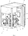
- Fig. 1 shows a compressor system 01 according to the invention in a partially opened, perspective view.
- the compressor system 01 has a closable system housing 02, the side walls 03 of which are only partially shown.
- the system housing 02 comprises a base 04 and a door 05, which allows access to system components 06 located on the inside.
- the system components 06 generate heat when the compressor system is in operation and comprise at least one compressor stage for compressing a gaseous medium.
- the door 05 has a first section of a cooling air duct 07, which has an inlet opening 08 at the top and an outlet opening 09 at the bottom.
- a passage 11 is arranged in the bottom 04, which is coupled to the outlet opening 09 when the door 05 is closed in order to allow cooling air to flow into the bottom 04.
- the cooling air duct is thus composed of the section running in the door, sections in the floor and sections within the system housing, which, for. B. are formed by the air guide elements.
- Fig. 2 shows the compressor system 01 in an open view, several of the system components not being shown. This shows that in the upper An air-water cooler 12 is arranged in the third of the system housing and is therefore located above the heat-generating system components 06. A plurality of upper air guiding elements 13 are arranged in the system housing and guide the rising, heated air - symbolized by hot air arrows 14 - to the air-water cooler 12.
- a blower 15 is arranged above the air-water cooler 12 to generate a circulated cooling air flow. This sucks the warm air through the air-water cooler 12 and blows the cooled air there as cooling air flow 16 to the inlet opening 08 of the cooling air duct 07.
- the cooling air flow 16 is guided downward in the cooling air duct 07 and exits from the outlet opening 09 in order to pass through the passage 11 to get into the floor 04.
- Lower air guiding elements 17 are arranged in the bottom 04 and possibly also in the lower section of the system housing in order to guide the cooling air flow to the system components 06 to be cooled.
- Fig. 3 shows a simplified longitudinal sectional view of a pulsation muffler 100, which is a system component of the compressor system described above.
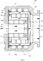
- Fig. 4 shows the cross section of this pulsation silencer.
- the muffler 100 has an essentially cylindrical muffler housing 101 with an absorber element receiving area 102, an end plate 103 closing the end of the muffler housing and a flange 104 axially opposite the end plate.
- the end plate 103 has a centrally arranged media flow inlet 106 to which a gaseous media stream 107, in particular compressed air, compressed by a compressor is supplied.
- a plurality of sleeve-like absorber elements 108 are arranged in the absorber element receiving area 102, in the example shown a fluidic front absorber element 108a, a fluidic middle absorber element 108b and a fluidic rear absorber element 108c.
- the three absorber elements are telescoped and have essentially the same length in the axial direction. All absorber elements consist of sound-absorbing material, whereby the specific properties of the material between the individual absorber elements can be selected differently.
- the media stream inlet 106 opens into the centrally located inlet area of the front absorber element 108a, so that the media stream first flows inside the front absorber element 108a and is damped by its material.
- the interior of the front absorber element 108a can be hollow or filled with gas-permeable material, the flow resistance being kept low.
- an outlet area is provided at the end of the front absorber element 108a facing away from the end plate 103, so that the media stream can emerge from the front absorber element 108a.
- the media stream flows in a first annular changing area 110 into the inlet area of the middle absorber element 108b, with a reversal of direction in the media stream 107.
- the middle absorber element 108b encircles the front absorber element 108a in terms of flow technology, a centering mandrel 111 provided on the middle absorber element 108b serving to hold the front absorber element 108a.
- the media stream 107 now flows through a first cylindrical flow space 112, which extends between the front absorber element 108a and the middle absorber element 108b in the axial direction.
- the media stream leaves the first cylindrical flow space 112 via an outlet area and flows into the inlet area of the rear absorber element 108c in a second annular changing area 113.
- the media stream 107 flows through a second cylindrical flow space 114, which extends in the axial direction between the middle absorber element 108b and the rear absorber element 108c.
- the direction of flow in the second flow space 114 is axially opposite to the flow direction in the first flow space 112.
- the media stream 107 leaves the absorber element receiving region 102 via an outlet area of the aerodynamically rear absorber element 108c and then flows through a media flow outlet 116 in the flange 104 to the downstream units of the compressor. It can be seen from the figures that the cross section available for the media stream increases significantly in each case in the changing regions and is ultimately significantly larger at the media stream outlet 116 than at the media stream inlet 106.
- all three absorber elements 108 each have a plurality of resonator chambers 117a, 117b and 117c in their walls.
- Fig. 5 shows the basic structure of a compressor system that uses a double screw compressor 200 as a system component.
- a double screw compressor 200 as a system component.
- a first compressor stage 201 has a first direct drive 202, which is speed-controlled.
- the inlet of the first compressor stage 201 via which ambient air is drawn in, is directly coupled to an intake port 203, without the interposition of an intake regulator, at which ambient atmosphere with a pressure of 1.0 bar at a temperature of, for. B. 20 ° C is present.
- a pressure of 1.0 bar is therefore present at the inlet of the first compressor stage 201.
- the first compressor stage 201 is, for. B. operated at a speed of 15,500 min -1 to compress the air. A pressure of 3.2 bar then prevails at the outlet of the first compressor stage 201, so that the first compressor stage has a compression ratio of 3.2 during load operation. Compression increases the temperature of the medium (compressed air) to 170 ° C.
- the compressed air is fed from the outlet of the first compressor stage 201 via an intercooler 204 to the inlet of a second compressor stage 206, which has a second, speed-controlled direct drive 207.
- the waste heat generated at the intercooler 204 must be removed from the compressor system.
- the air circulating in the system housing 02 is cooled by the air-water cooler 12.
- the cooling water flowing in the air-water cooler can be conducted in a parallel branch or in series connection through the intercooler 204 if it has water cooling.
- the compressed air has a temperature of, for example, 30 ° C. and a pressure of 3.2 bar. in the Load operation, the second compressor stage 206 with a speed of z. B. 22,000 min -1 operated, so that there is a further compression.
- the compressed air consequently has a pressure of 10.2 bar and a temperature of 180 ° C. at the outlet of the second compressor stage 206.
- the second compressor stage thus also has a compression ratio of approximately 3.2.
- the compressed air is guided from the outlet of the second compressor stage 206 through an aftercooler 208 and cooled there to about 35 ° C.
- the aftercooler 208 can also be integrated into the cooling water circuit, which supplies the air-water cooler 12 and / or the intercooler 204.
- a blow-off valve 209 is arranged at the outlet of the double screw compressor 200 and is controlled by a control unit (not shown).
- the double screw compressor 200 described by way of example shows a power consumption of 150 kW at the maximum speed of the direct drives 202, 207 and delivers compressed air with a maximum pressure of 12 bar and a minimum pressure of 6 bar.
- the speed ratio between the compressor stages is approximately 1.4 in load operation.
- Fig. 6 shows the twin screw compressor 200 in idle mode, ie when essentially no compressed air is drawn off.
- typical parameters are given as they occur in idle mode.
- the blow-off valve is opened and the speed of both compressor stages is reduced.
- the inlet of the first compressor stage 201 via which ambient air continues to be sucked in, albeit in a reduced amount, is furthermore directly coupled to the intake port 203, at which ambient atmosphere with a pressure of, without the interposition of a suction regulator 1.0 bar at a temperature of 20 ° C. A pressure of 1.0 bar is therefore unchanged at the inlet of the first compressor stage 201.
- a pressure of 1.5 bar then prevails at the outlet of the first compressor stage 201, so that the first compressor stage has a compression ratio of 1.5 when idling.
- Due to the reduced compression the temperature of the medium (compressed air) only increases to 90 ° C.
- the compressed air is led from the outlet of the first compressor stage 201 via the intercooler 204 to the inlet of the second compressor stage 206.
- the compressed air at idle has a temperature of, for example, 30 ° C. and also a pressure of 1.5 bar (intermediate pressure).
- the second compressor stage 206 is operated at an idling speed V2 L of 7.500 min -1.
- the compressed air has a pressure of approximately 1.2 bar, which is reduced compared to the intermediate pressure, and a temperature of 70 ° C.
- the second compressor stage thus has a compression ratio of approximately 0.8 (expansion).
- the compressed air is led from the outlet of the second compressor stage 206 through the aftercooler 208 and cooled there to about 30 ° C.
- the double screw compressor 200 described by way of example shows a power consumption of 7 kW in idle mode and delivers a maximum pressure of 1.2 bar.
- the speed ratio between the compressor stages is about 3.
Landscapes
- Engineering & Computer Science (AREA)
- Mechanical Engineering (AREA)
- General Engineering & Computer Science (AREA)
- Applications Or Details Of Rotary Compressors (AREA)
- Physics & Mathematics (AREA)
- Fluid Mechanics (AREA)
Claims (9)
- Système de compresseur (01) comportant un boîtier de système (02) dans lequel sont disposés :- des composants de système générateurs de chaleur (06) qui comprennent au moins un niveau compresseur (201) pour compresser un milieu gazeux ;- un refroidisseur à air-eau (12) qui est positionné au-dessus des composants de système générateurs de chaleur (06) ;- une soufflerie (15) qui génère un flux d'air de refroidissement (16) ;- des éléments conducteurs d'air qui guident l'air chauffé par les composants de système (06) vers le refroidisseur à air-eau (12) ;dans lequel est constitué un canal d'air de refroidissement (07) qui présente une ouverture d'admission (08) dans la section supérieure du boîtier de système (02) et une ouverture d'évacuation (09) dans la section inférieure du boîtier de système (02), les éléments conducteurs d'air supérieurs (13) étant positionnés de manière à guider le flux d'air de refroidissement (16), après son passage dans le refroidisseur à air-eau (12), vers l'ouverture d'admission (08), les éléments conducteurs d'air inférieurs (17) sont positionnés de manière à guider le flux d'air de refroidissement (16) depuis l'ouverture d'évacuation (09) jusqu'aux composants de système (06), et caractérisé en ce que la soufflerie (15) est positionnée au-dessus du refroidisseur à air-eau (12) de manière à aspirer le flux d'air de refroidissement (16) à travers le refroidisseur à air-eau (12) et à le guider vers l'ouverture d'admission (08) du canal d'air de refroidissement (07).
- Système de compresseur (01) selon la revendication 1, caractérisé en ce que le canal de refroidissement d'air (07) s'étend au moins par sections dans une porte (05) fermant le boîtier de système (02).
- Système de compresseur (01) selon une des revendications 1 à 2, caractérisé en ce que le canal de refroidissement d'air (07) s'étend par sections dans un fond (04) du boîtier de système (02) et présente là plusieurs ouvertures d'évacuation qui évacuent l'air de refroidissement vers le haut dans le boîtier de système (02).
- Système de compresseur (01) selon une des revendications 1 à 3, caractérisé en ce que le boîtier de système (02) est colmaté de manière étanche à l'air par rapport à l'environnement, le niveau compresseur (201) étant raccordé à une tubulure d'aspiration (203) ouverte sur l'environnement.
- Système de compresseur (01) selon une des revendications 1 à 4, caractérisé en ce que les composants de système générateurs de chaleur (06) comprennent un sous-ensemble de commutation électronique.
- Système de compresseur (01) selon une des revendications 1 à 5, caractérisé en ce que le refroidisseur à air-eau (12) est raccordable à un circuit de refroidissement externe qui présente une unité de récupération de chaleur.
- Système de compresseur (01) selon une des revendications 1 à 6, caractérisé en ce que :- les composants de système générateurs de chaleur (06) comprennent un compresseur à vis comportant un premier et un second niveau compresseur (201,206), le premier niveau compresseur (201) comprimant le milieu gazeux et le guidant vers le second niveau compresseur (206) qui continue à comprimer le milieu,- les deux niveaux compresseurs (201,206) sont entraînés séparément l'un de l'autre et avec possibilité de réglage de la vitesse de rotation ;- il est prévu une soupape de soufflage (209) qui s'ouvre lorsque le flux volumique absorbé par le second niveau compresseur (206) passe en dessous d'une valeur minimale prédéfinie, la vitesse de rotation d'au moins le premier niveau compresseur (201) étant réduite à une vitesse de rotation à vide prédéfinie (V1L) afin de réduire le flux volumique délivré par le premier niveau compresseur au second.
- Système de compresseur (01) selon une des revendications 1 à 7, caractérisé en ce que :- les composants de système générateurs de chaleur (06) comprennent un insonorisateur à pulsation (100) disposé dans le boîtier de système (02) et qui est disposé en ce qui concerne la technique d'écoulement en aval du dernier niveau compresseur (206) et comprend de son côté :- un boîtier insonorisateur (101) s'étendant le long d'un axe central et comportant une admission de flux de milieu (106) et une évacuation de flux de milieu (116) ;- plusieurs éléments absorbeurs en forme de manchons (108) qui sont composés de matériau insonorisant et sont disposés concentriquement les uns par rapport aux autres dans le boîtier insonorisateur (101),∘ chaque élément absorbeur en forme de manchon (108) possédant une zone d'admission et une zone d'évacuation qui sont positionnées espacées axialement l'une de l'autre, et∘ la zone d'admission de l'élément absorbant (108a) situé le plus en avant en ce qui concerne la technique d'écoulement étant connectée à l'admission de flux de milieu (106) du boîtier insonorisateur (101), la zone d'évacuation de l'élément absorbant (108a) situé le plus en avant en ce qui concerne la technique d'écoulement étant connectée à la zone d'admission de l'élément absorbant suivant en ce qui concerne la technique d'écoulement (108b), et ainsi de suite, et la zone d'évacuation de l'élément absorbant (108c) situé le plus en arrière en ce qui concerne la technique d'écoulement étant connectée à l'évacuation de flux de milieu (116) du boîtier insonorisateur (101),∘ respectivement un espace d'écoulement (112,114) pour le flux de milieu (107) restant entre des sections de parois radialement voisines de différents éléments absorbants (108).
- Système de compresseur (01) selon la revendication 8, caractérisé en ce que les éléments absorbants (108) de l'insonorisateur à pulsation (100) ont une conformation symétrique en rotation et s'engrènent les uns dans les autres de manière télescopique mais fixe axialement.
Applications Claiming Priority (1)
| Application Number | Priority Date | Filing Date | Title |
|---|---|---|---|
| DE102017107602.6A DE102017107602B3 (de) | 2017-04-10 | 2017-04-10 | Kompressoranlage mit interner Luft-Wasser-Kühlung |
Publications (2)
| Publication Number | Publication Date |
|---|---|
| EP3388621A1 EP3388621A1 (fr) | 2018-10-17 |
| EP3388621B1 true EP3388621B1 (fr) | 2020-02-19 |
Family
ID=61868197
Family Applications (1)
| Application Number | Title | Priority Date | Filing Date |
|---|---|---|---|
| EP18164786.8A Active EP3388621B1 (fr) | 2017-04-10 | 2018-03-28 | Installation de compresseur à refroidissement à air et à eau interne |
Country Status (6)
| Country | Link |
|---|---|
| US (1) | US10816001B2 (fr) |
| EP (1) | EP3388621B1 (fr) |
| CN (2) | CN121654599A (fr) |
| CA (1) | CA3000501A1 (fr) |
| DE (1) | DE102017107602B3 (fr) |
| ES (1) | ES2790580T3 (fr) |
Families Citing this family (12)
| Publication number | Priority date | Publication date | Assignee | Title |
|---|---|---|---|---|
| BE1026208B1 (nl) * | 2018-04-12 | 2019-11-13 | Atlas Copco Airpower Naamloze Vennootschap | Oliegeïnjecteerde schroefcompressorinrichting |
| BE1026205B1 (nl) * | 2018-04-12 | 2019-11-12 | Atlas Copco Airpower Naamloze Vennootschap | Meertrapscompressor en werkwijze voor het instellen van het toerental van de motoren |
| US20200109713A1 (en) * | 2018-10-09 | 2020-04-09 | Hi-Bar Blowers, Inc. | Integrated rotary positive-displacement machinery |
| DE102019102387A1 (de) | 2019-01-30 | 2020-07-30 | Gardner Denver Deutschland Gmbh | Kühlungsanordnung und Verfahren zur Kühlung eines mindestens zweistufigen Drucklufterzeugers |
| DE202019101290U1 (de) * | 2019-03-07 | 2020-06-09 | KFB Acoustics Sp. z o.o. | Schalldämpfer |
| US11994136B2 (en) * | 2019-08-01 | 2024-05-28 | Danfoss A/S | Power electronics cooling arrangement |
| CN114738236B (zh) * | 2021-04-24 | 2024-04-26 | 阿特拉斯·科普柯(印度)有限公司 | 压缩空气生成系统 |
| BE1029818B1 (nl) * | 2021-10-04 | 2023-05-03 | Atlas Copco Airpower Nv | Luchtgekoelde inrichting en werkwijze voor het aansturen van een luchtgekoelde inrichting |
| BE1029816B1 (nl) * | 2021-10-04 | 2023-05-02 | Atlas Copco Airpower Nv | Samenstel voor het samenpersen van gas, werkwijze voor het koelen en gebruik van dergelijk samenstel |
| CN114837946B (zh) * | 2022-06-18 | 2023-03-24 | 华海(北京)科技股份有限公司 | 一种节能型双级螺旋式空气压缩机控制系统 |
| DE102022207205A1 (de) * | 2022-07-14 | 2024-01-25 | Deutsches Zentrum für Luft- und Raumfahrt e.V. | Vorrichtung und Verfahren zur Bereitstellung von Wärme und Druckluft |
| CN119901026B (zh) * | 2025-02-06 | 2025-10-10 | 烟台职业学院 | 一种立式全封闭螺杆压缩机 |
Family Cites Families (45)
| Publication number | Priority date | Publication date | Assignee | Title |
|---|---|---|---|---|
| US1953543A (en) * | 1932-07-23 | 1934-04-03 | George C Rensink | Air cleaner and silencer for internal combustion engines |
| DE1628835A1 (de) | 1966-04-02 | 1971-06-16 | Altenburg Elektrowaerme | Einrichtung zur Geraeuschminderung an elektromotorisch angetriebenen Geraeten |
| DE2737677C2 (de) | 1977-08-20 | 1984-05-10 | M.A.N. Maschinenfabrik Augsburg-Nürnberg AG, 4200 Oberhausen | Einrichtung zur Fördermengenregelung von Verdichtern |
| DE2909675C3 (de) | 1979-03-12 | 1981-11-19 | M.A.N. Maschinenfabrik Augsburg-Nürnberg AG, 4200 Oberhausen | Verfahren zur kondensatfreien Zwischenkühlung verdichteter Gase |
| FR2598176B1 (fr) | 1986-04-30 | 1990-01-19 | Boet Sa Andre | Silencieux pour courant gazeux |
| US4929161A (en) * | 1987-10-28 | 1990-05-29 | Hitachi, Ltd. | Air-cooled oil-free rotary-type compressor |
| JPH03108818U (fr) | 1990-02-21 | 1991-11-08 | ||
| DE9014888U1 (de) | 1990-10-27 | 1991-01-24 | Leybold AG, 6450 Hanau | Schalldämpfer |
| FR2713702B1 (fr) | 1993-12-14 | 1996-03-01 | Boet Sa Andre | Silencieux pour courant gazeux. |
| JP3296205B2 (ja) | 1996-09-20 | 2002-06-24 | 株式会社日立製作所 | オイルフリースクロール圧縮機およびその冷却システム |
| NL1006892C2 (nl) | 1997-08-29 | 1999-03-02 | Q E International Bv | Pulsatiedemper. |
| SE512070C2 (sv) * | 1998-03-18 | 2000-01-24 | Tetra Laval Holdings & Finance | Anordning för högtryckspumpning eller homogenisering av vätskor |
| US6095194A (en) | 1998-03-20 | 2000-08-01 | Nippon Pillar Packaging Co., Ltd. | Pulsation suppression device for a pump |
| US6068447A (en) | 1998-06-30 | 2000-05-30 | Standard Pneumatic Products, Inc. | Semi-automatic compressor controller and method of controlling a compressor |
| BE1012944A3 (nl) | 1999-10-26 | 2001-06-05 | Atlas Copco Airpower Nv | Meertraps-compressoreenheid en werkwijze voor het regelen van een der gelijke meertraps-compressoreenheid. |
| DE10003869C5 (de) | 2000-01-28 | 2007-11-08 | Aerzener Maschinenfabrik Gmbh | Verfahren zum Komprimieren von fluiden Fördermedien |
| GB2367332B (en) | 2000-09-25 | 2003-12-03 | Compair Uk Ltd | Improvements in multi-stage screw compressor drive arrangements |
| JP3817420B2 (ja) * | 2000-10-31 | 2006-09-06 | 株式会社日立産機システム | 回転速度可変形オイルフリースクリュー圧縮機およびその運転制御方法 |
| US6595757B2 (en) | 2001-11-27 | 2003-07-22 | Kuei-Hsien Shen | Air compressor control system |
| US7118348B2 (en) | 2003-03-06 | 2006-10-10 | General Electric Company | Compressed air system and method of control |
| EP1703618B1 (fr) | 2005-03-14 | 2013-05-15 | Kaeser Kompressoren AG | Moteur électrique à refroidissement par air |
| JP4673136B2 (ja) * | 2005-06-09 | 2011-04-20 | 株式会社日立産機システム | スクリュー圧縮機 |
| FR2890418A1 (fr) | 2005-09-02 | 2007-03-09 | Atlas Copco Crepelle S A S | Installation de compression haute pression a plusieurs etages |
| EP1984628B1 (fr) | 2006-02-13 | 2014-12-17 | Ingersoll-Rand Company | Systeme de compression a plusieurs etages et son procede d'actionnement |
| NL1031270C2 (nl) | 2006-03-02 | 2007-09-04 | Ecoplay Int Bv | Leidingstelsel voor water met bewaking tegen aftakkingen, systeem en werkwijze daarvoor. |
| US8303260B2 (en) | 2006-03-08 | 2012-11-06 | Itt Manufacturing Enterprises, Inc. | Method and apparatus for pump protection without the use of traditional sensors |
| DE102006020334B4 (de) * | 2006-04-28 | 2008-07-10 | Man Diesel Se | Filterschalldämpfer |
| JP4741992B2 (ja) * | 2006-07-19 | 2011-08-10 | 株式会社日立産機システム | オイルフリースクリュー圧縮機 |
| JP2008133811A (ja) | 2006-11-29 | 2008-06-12 | Hitachi Ltd | パッケージ型圧縮機 |
| JP5248373B2 (ja) * | 2009-03-11 | 2013-07-31 | 株式会社日立産機システム | 水噴射式空気圧縮機 |
| JP2010275939A (ja) * | 2009-05-29 | 2010-12-09 | Hitachi Industrial Equipment Systems Co Ltd | 水冷式オイルフリー空気圧縮機 |
| BE1019299A3 (nl) | 2010-04-20 | 2012-05-08 | Atlas Copco Airpower Nv | Wekwijze voor het aansturen van een compressor. |
| JP4737341B1 (ja) * | 2010-08-10 | 2011-07-27 | 株式会社安川電機 | 回転電機および風力発電システム |
| WO2012026317A1 (fr) * | 2010-08-27 | 2012-03-01 | 株式会社日立産機システム | Compresseur de gaz refroidi par huile |
| CN202073748U (zh) * | 2011-03-03 | 2011-12-14 | 中国石油天然气股份有限公司 | 压缩机空冷器热风循环装置 |
| JP5774455B2 (ja) | 2011-11-30 | 2015-09-09 | 株式会社日立産機システム | 無給油式圧縮機 |
| CN203335413U (zh) * | 2013-06-26 | 2013-12-11 | 上海申行健压缩机有限公司 | 一种高节能离心式冷却系统 |
| EP2886862B1 (fr) | 2013-12-17 | 2020-09-02 | Kaeser Kompressoren Se | Compresseur |
| JP5728738B2 (ja) * | 2014-01-08 | 2015-06-03 | オリオン機械株式会社 | パッケージ型の回転ポンプユニット |
| DE102014107126A1 (de) | 2014-05-20 | 2015-11-26 | Harald Wenzel | Mehrstufige Verdichteranlage zur Erzeugung eines komprimierten Gase |
| JP6382672B2 (ja) * | 2014-10-02 | 2018-08-29 | 株式会社日立産機システム | パッケージ型圧縮機 |
| JP2016145557A (ja) | 2015-02-09 | 2016-08-12 | アネスト岩田株式会社 | パッケージ型流体機械 |
| DE102016100140A1 (de) | 2016-01-05 | 2017-07-06 | Knorr-Bremse Systeme für Nutzfahrzeuge GmbH | Geräuschdämpfer für ein Druckluftsystem eines Fahrzeugs, insbesondere eines Nutzfahrzeugs |
| CN205388001U (zh) * | 2016-03-25 | 2016-07-20 | 石家庄旭特压缩机有限公司 | 一种新能源电车专用空气压缩机外壳 |
| US10359044B2 (en) * | 2016-05-06 | 2019-07-23 | Powerex/Scott Fetzer Company | Compressor system |
-
2017
- 2017-04-10 DE DE102017107602.6A patent/DE102017107602B3/de active Active
-
2018
- 2018-03-28 ES ES18164786T patent/ES2790580T3/es active Active
- 2018-03-28 EP EP18164786.8A patent/EP3388621B1/fr active Active
- 2018-04-09 CA CA3000501A patent/CA3000501A1/fr not_active Abandoned
- 2018-04-10 CN CN202511734046.0A patent/CN121654599A/zh active Pending
- 2018-04-10 CN CN201810316479.8A patent/CN108691771A/zh active Pending
- 2018-04-10 US US15/950,098 patent/US10816001B2/en active Active
Non-Patent Citations (1)
| Title |
|---|
| None * |
Also Published As
| Publication number | Publication date |
|---|---|
| US20180291904A1 (en) | 2018-10-11 |
| US10816001B2 (en) | 2020-10-27 |
| EP3388621A1 (fr) | 2018-10-17 |
| CA3000501A1 (fr) | 2018-10-10 |
| ES2790580T3 (es) | 2020-10-28 |
| CN121654599A (zh) | 2026-03-13 |
| CN108691771A (zh) | 2018-10-23 |
| DE102017107602B3 (de) | 2018-09-20 |
Similar Documents
| Publication | Publication Date | Title |
|---|---|---|
| DE102017107602B3 (de) | Kompressoranlage mit interner Luft-Wasser-Kühlung | |
| DE69620669T2 (de) | Lärmdämpfungsgerät eines Lüfters | |
| EP3145638B1 (fr) | Centrifugeuse | |
| DE102010022993B4 (de) | Transportkältemaschine zum Kühlen des Innenraums | |
| DE60123321T2 (de) | Verdichteranlage mit einem gesteuerten Kühlventilator | |
| DE3444057A1 (de) | Klimaanlage mit luftumwaelzung | |
| EP1703618B1 (fr) | Moteur électrique à refroidissement par air | |
| DE2942565C2 (de) | Anlage zur Verdampfung eines flüssigen Mediums | |
| DE60307662T2 (de) | Kompressor mit leistungsregelung | |
| EP3601797B1 (fr) | Compresseur à piston avec une zone de reglage étendu | |
| DE102018205269B4 (de) | Schraubenverdichter | |
| DE202017104181U1 (de) | Kühlgebläse für kältemittelgekühlten Motor | |
| EP3933207B1 (fr) | Ventilateur médical avec système d'isolation acoustique, en particulier pour usage dentaire | |
| DE19817351A1 (de) | Schraubenspindel-Vakuumpumpe mit Gaskühlung | |
| DE2303964A1 (de) | Kaelteanlage | |
| DE102016011507A1 (de) | Schraubenkompressorsystem für ein Nutzfahrzeug | |
| EP4237759A1 (fr) | Machine frigorifique à gaz, procédé de fonctionnement d'une machine frigorifique à gaz et procédé de fabrication d'une machine frigorifique à gaz comprenant un récupérateur autour de la zone d'aspiration | |
| EP1600314B1 (fr) | Arrangement et procédé d'operation dans un circuit de réfrigérant | |
| EP3370491A1 (fr) | Système de refroidissement destiné au refroidissement d'une armoire de serveur disposée dans un espace | |
| EP2006508A2 (fr) | Unité d'alimentation dotée d'un agrégat de générateur/moteur en tant que générateur de courant | |
| DE69529321T2 (de) | Turboverdichter | |
| DE202010017392U1 (de) | Transportkältemaschine zum Kühlen des Innenraums | |
| EP3277958B1 (fr) | Système de compresseur pour la production d'air comprimé et procédé pour faire fonctionner un système de compresseur produisant de l'air comprimé | |
| DE1806519A1 (de) | Verfahren und Vorrichtung zum Aufheizen von Gasen,insbesondere Luft | |
| DE102006011380B4 (de) | Wärmekraftmaschine |
Legal Events
| Date | Code | Title | Description |
|---|---|---|---|
| PUAI | Public reference made under article 153(3) epc to a published international application that has entered the european phase |
Free format text: ORIGINAL CODE: 0009012 |
|
| STAA | Information on the status of an ep patent application or granted ep patent |
Free format text: STATUS: THE APPLICATION HAS BEEN PUBLISHED |
|
| AK | Designated contracting states |
Kind code of ref document: A1 Designated state(s): AL AT BE BG CH CY CZ DE DK EE ES FI FR GB GR HR HU IE IS IT LI LT LU LV MC MK MT NL NO PL PT RO RS SE SI SK SM TR |
|
| AX | Request for extension of the european patent |
Extension state: BA ME |
|
| STAA | Information on the status of an ep patent application or granted ep patent |
Free format text: STATUS: REQUEST FOR EXAMINATION WAS MADE |
|
| 17P | Request for examination filed |
Effective date: 20190405 |
|
| RBV | Designated contracting states (corrected) |
Designated state(s): AL AT BE BG CH CY CZ DE DK EE ES FI FR GB GR HR HU IE IS IT LI LT LU LV MC MK MT NL NO PL PT RO RS SE SI SK SM TR |
|
| RIC1 | Information provided on ipc code assigned before grant |
Ipc: F04C 29/12 20060101ALI20190425BHEP Ipc: F01C 21/00 20060101AFI20190425BHEP |
|
| GRAP | Despatch of communication of intention to grant a patent |
Free format text: ORIGINAL CODE: EPIDOSNIGR1 |
|
| STAA | Information on the status of an ep patent application or granted ep patent |
Free format text: STATUS: GRANT OF PATENT IS INTENDED |
|
| GRAJ | Information related to disapproval of communication of intention to grant by the applicant or resumption of examination proceedings by the epo deleted |
Free format text: ORIGINAL CODE: EPIDOSDIGR1 |
|
| STAA | Information on the status of an ep patent application or granted ep patent |
Free format text: STATUS: REQUEST FOR EXAMINATION WAS MADE |
|
| INTG | Intention to grant announced |
Effective date: 20190606 |
|
| INTC | Intention to grant announced (deleted) | ||
| GRAP | Despatch of communication of intention to grant a patent |
Free format text: ORIGINAL CODE: EPIDOSNIGR1 |
|
| STAA | Information on the status of an ep patent application or granted ep patent |
Free format text: STATUS: GRANT OF PATENT IS INTENDED |
|
| INTG | Intention to grant announced |
Effective date: 20190912 |
|
| GRAS | Grant fee paid |
Free format text: ORIGINAL CODE: EPIDOSNIGR3 |
|
| GRAA | (expected) grant |
Free format text: ORIGINAL CODE: 0009210 |
|
| STAA | Information on the status of an ep patent application or granted ep patent |
Free format text: STATUS: THE PATENT HAS BEEN GRANTED |
|
| AK | Designated contracting states |
Kind code of ref document: B1 Designated state(s): AL AT BE BG CH CY CZ DE DK EE ES FI FR GB GR HR HU IE IS IT LI LT LU LV MC MK MT NL NO PL PT RO RS SE SI SK SM TR |
|
| REG | Reference to a national code |
Ref country code: CH Ref legal event code: EP |
|
| REG | Reference to a national code |
Ref country code: DE Ref legal event code: R096 Ref document number: 502018000780 Country of ref document: DE |
|
| REG | Reference to a national code |
Ref country code: AT Ref legal event code: REF Ref document number: 1235178 Country of ref document: AT Kind code of ref document: T Effective date: 20200315 |
|
| REG | Reference to a national code |
Ref country code: IE Ref legal event code: FG4D Free format text: LANGUAGE OF EP DOCUMENT: GERMAN |
|
| REG | Reference to a national code |
Ref country code: NL Ref legal event code: MP Effective date: 20200219 |
|
| PG25 | Lapsed in a contracting state [announced via postgrant information from national office to epo] |
Ref country code: RS Free format text: LAPSE BECAUSE OF FAILURE TO SUBMIT A TRANSLATION OF THE DESCRIPTION OR TO PAY THE FEE WITHIN THE PRESCRIBED TIME-LIMIT Effective date: 20200219 Ref country code: FI Free format text: LAPSE BECAUSE OF FAILURE TO SUBMIT A TRANSLATION OF THE DESCRIPTION OR TO PAY THE FEE WITHIN THE PRESCRIBED TIME-LIMIT Effective date: 20200219 Ref country code: NO Free format text: LAPSE BECAUSE OF FAILURE TO SUBMIT A TRANSLATION OF THE DESCRIPTION OR TO PAY THE FEE WITHIN THE PRESCRIBED TIME-LIMIT Effective date: 20200519 |
|
| REG | Reference to a national code |
Ref country code: LT Ref legal event code: MG4D |
|
| PG25 | Lapsed in a contracting state [announced via postgrant information from national office to epo] |
Ref country code: GR Free format text: LAPSE BECAUSE OF FAILURE TO SUBMIT A TRANSLATION OF THE DESCRIPTION OR TO PAY THE FEE WITHIN THE PRESCRIBED TIME-LIMIT Effective date: 20200520 Ref country code: BG Free format text: LAPSE BECAUSE OF FAILURE TO SUBMIT A TRANSLATION OF THE DESCRIPTION OR TO PAY THE FEE WITHIN THE PRESCRIBED TIME-LIMIT Effective date: 20200519 Ref country code: HR Free format text: LAPSE BECAUSE OF FAILURE TO SUBMIT A TRANSLATION OF THE DESCRIPTION OR TO PAY THE FEE WITHIN THE PRESCRIBED TIME-LIMIT Effective date: 20200219 Ref country code: SE Free format text: LAPSE BECAUSE OF FAILURE TO SUBMIT A TRANSLATION OF THE DESCRIPTION OR TO PAY THE FEE WITHIN THE PRESCRIBED TIME-LIMIT Effective date: 20200219 Ref country code: IS Free format text: LAPSE BECAUSE OF FAILURE TO SUBMIT A TRANSLATION OF THE DESCRIPTION OR TO PAY THE FEE WITHIN THE PRESCRIBED TIME-LIMIT Effective date: 20200619 Ref country code: LV Free format text: LAPSE BECAUSE OF FAILURE TO SUBMIT A TRANSLATION OF THE DESCRIPTION OR TO PAY THE FEE WITHIN THE PRESCRIBED TIME-LIMIT Effective date: 20200219 |
|
| PG25 | Lapsed in a contracting state [announced via postgrant information from national office to epo] |
Ref country code: NL Free format text: LAPSE BECAUSE OF FAILURE TO SUBMIT A TRANSLATION OF THE DESCRIPTION OR TO PAY THE FEE WITHIN THE PRESCRIBED TIME-LIMIT Effective date: 20200219 |
|
| REG | Reference to a national code |
Ref country code: ES Ref legal event code: FG2A Ref document number: 2790580 Country of ref document: ES Kind code of ref document: T3 Effective date: 20201028 |
|
| PG25 | Lapsed in a contracting state [announced via postgrant information from national office to epo] |
Ref country code: SM Free format text: LAPSE BECAUSE OF FAILURE TO SUBMIT A TRANSLATION OF THE DESCRIPTION OR TO PAY THE FEE WITHIN THE PRESCRIBED TIME-LIMIT Effective date: 20200219 Ref country code: EE Free format text: LAPSE BECAUSE OF FAILURE TO SUBMIT A TRANSLATION OF THE DESCRIPTION OR TO PAY THE FEE WITHIN THE PRESCRIBED TIME-LIMIT Effective date: 20200219 Ref country code: SK Free format text: LAPSE BECAUSE OF FAILURE TO SUBMIT A TRANSLATION OF THE DESCRIPTION OR TO PAY THE FEE WITHIN THE PRESCRIBED TIME-LIMIT Effective date: 20200219 Ref country code: DK Free format text: LAPSE BECAUSE OF FAILURE TO SUBMIT A TRANSLATION OF THE DESCRIPTION OR TO PAY THE FEE WITHIN THE PRESCRIBED TIME-LIMIT Effective date: 20200219 Ref country code: PT Free format text: LAPSE BECAUSE OF FAILURE TO SUBMIT A TRANSLATION OF THE DESCRIPTION OR TO PAY THE FEE WITHIN THE PRESCRIBED TIME-LIMIT Effective date: 20200712 Ref country code: RO Free format text: LAPSE BECAUSE OF FAILURE TO SUBMIT A TRANSLATION OF THE DESCRIPTION OR TO PAY THE FEE WITHIN THE PRESCRIBED TIME-LIMIT Effective date: 20200219 Ref country code: CZ Free format text: LAPSE BECAUSE OF FAILURE TO SUBMIT A TRANSLATION OF THE DESCRIPTION OR TO PAY THE FEE WITHIN THE PRESCRIBED TIME-LIMIT Effective date: 20200219 Ref country code: LT Free format text: LAPSE BECAUSE OF FAILURE TO SUBMIT A TRANSLATION OF THE DESCRIPTION OR TO PAY THE FEE WITHIN THE PRESCRIBED TIME-LIMIT Effective date: 20200219 |
|
| REG | Reference to a national code |
Ref country code: DE Ref legal event code: R097 Ref document number: 502018000780 Country of ref document: DE |
|
| PG25 | Lapsed in a contracting state [announced via postgrant information from national office to epo] |
Ref country code: MC Free format text: LAPSE BECAUSE OF FAILURE TO SUBMIT A TRANSLATION OF THE DESCRIPTION OR TO PAY THE FEE WITHIN THE PRESCRIBED TIME-LIMIT Effective date: 20200219 |
|
| PLBE | No opposition filed within time limit |
Free format text: ORIGINAL CODE: 0009261 |
|
| STAA | Information on the status of an ep patent application or granted ep patent |
Free format text: STATUS: NO OPPOSITION FILED WITHIN TIME LIMIT |
|
| PG25 | Lapsed in a contracting state [announced via postgrant information from national office to epo] |
Ref country code: LU Free format text: LAPSE BECAUSE OF NON-PAYMENT OF DUE FEES Effective date: 20200328 |
|
| 26N | No opposition filed |
Effective date: 20201120 |
|
| PG25 | Lapsed in a contracting state [announced via postgrant information from national office to epo] |
Ref country code: IE Free format text: LAPSE BECAUSE OF NON-PAYMENT OF DUE FEES Effective date: 20200328 |
|
| PG25 | Lapsed in a contracting state [announced via postgrant information from national office to epo] |
Ref country code: SI Free format text: LAPSE BECAUSE OF FAILURE TO SUBMIT A TRANSLATION OF THE DESCRIPTION OR TO PAY THE FEE WITHIN THE PRESCRIBED TIME-LIMIT Effective date: 20200219 Ref country code: PL Free format text: LAPSE BECAUSE OF FAILURE TO SUBMIT A TRANSLATION OF THE DESCRIPTION OR TO PAY THE FEE WITHIN THE PRESCRIBED TIME-LIMIT Effective date: 20200219 |
|
| REG | Reference to a national code |
Ref country code: DE Ref legal event code: R082 Ref document number: 502018000780 Country of ref document: DE Representative=s name: MURGITROYD GERMANY PATENTANWALTSGESELLSCHAFT M, DE Ref country code: DE Ref legal event code: R082 Ref document number: 502018000780 Country of ref document: DE Representative=s name: MURGITROYD & COMPANY, DE |
|
| PGFP | Annual fee paid to national office [announced via postgrant information from national office to epo] |
Ref country code: ES Payment date: 20210405 Year of fee payment: 4 |
|
| REG | Reference to a national code |
Ref country code: CH Ref legal event code: PL |
|
| PG25 | Lapsed in a contracting state [announced via postgrant information from national office to epo] |
Ref country code: CH Free format text: LAPSE BECAUSE OF NON-PAYMENT OF DUE FEES Effective date: 20210331 Ref country code: LI Free format text: LAPSE BECAUSE OF NON-PAYMENT OF DUE FEES Effective date: 20210331 |
|
| PG25 | Lapsed in a contracting state [announced via postgrant information from national office to epo] |
Ref country code: TR Free format text: LAPSE BECAUSE OF FAILURE TO SUBMIT A TRANSLATION OF THE DESCRIPTION OR TO PAY THE FEE WITHIN THE PRESCRIBED TIME-LIMIT Effective date: 20200219 Ref country code: MT Free format text: LAPSE BECAUSE OF FAILURE TO SUBMIT A TRANSLATION OF THE DESCRIPTION OR TO PAY THE FEE WITHIN THE PRESCRIBED TIME-LIMIT Effective date: 20200219 Ref country code: CY Free format text: LAPSE BECAUSE OF FAILURE TO SUBMIT A TRANSLATION OF THE DESCRIPTION OR TO PAY THE FEE WITHIN THE PRESCRIBED TIME-LIMIT Effective date: 20200219 |
|
| PG25 | Lapsed in a contracting state [announced via postgrant information from national office to epo] |
Ref country code: MK Free format text: LAPSE BECAUSE OF FAILURE TO SUBMIT A TRANSLATION OF THE DESCRIPTION OR TO PAY THE FEE WITHIN THE PRESCRIBED TIME-LIMIT Effective date: 20200219 Ref country code: AL Free format text: LAPSE BECAUSE OF FAILURE TO SUBMIT A TRANSLATION OF THE DESCRIPTION OR TO PAY THE FEE WITHIN THE PRESCRIBED TIME-LIMIT Effective date: 20200219 |
|
| REG | Reference to a national code |
Ref country code: ES Ref legal event code: FD2A Effective date: 20230428 |
|
| P01 | Opt-out of the competence of the unified patent court (upc) registered |
Effective date: 20230523 |
|
| PG25 | Lapsed in a contracting state [announced via postgrant information from national office to epo] |
Ref country code: ES Free format text: LAPSE BECAUSE OF NON-PAYMENT OF DUE FEES Effective date: 20220329 |
|
| REG | Reference to a national code |
Ref country code: AT Ref legal event code: MM01 Ref document number: 1235178 Country of ref document: AT Kind code of ref document: T Effective date: 20230328 |
|
| PG25 | Lapsed in a contracting state [announced via postgrant information from national office to epo] |
Ref country code: AT Free format text: LAPSE BECAUSE OF NON-PAYMENT OF DUE FEES Effective date: 20230328 |
|
| PG25 | Lapsed in a contracting state [announced via postgrant information from national office to epo] |
Ref country code: AT Free format text: LAPSE BECAUSE OF NON-PAYMENT OF DUE FEES Effective date: 20230328 |
|
| PGFP | Annual fee paid to national office [announced via postgrant information from national office to epo] |
Ref country code: DE Payment date: 20250331 Year of fee payment: 8 |
|
| PGFP | Annual fee paid to national office [announced via postgrant information from national office to epo] |
Ref country code: GB Payment date: 20260330 Year of fee payment: 9 |
|
| PGFP | Annual fee paid to national office [announced via postgrant information from national office to epo] |
Ref country code: AT Payment date: 20260410 Year of fee payment: 5 |
|
| PGFP | Annual fee paid to national office [announced via postgrant information from national office to epo] |
Ref country code: BE Payment date: 20260324 Year of fee payment: 9 Ref country code: IT Payment date: 20260320 Year of fee payment: 9 |
|
| PGFP | Annual fee paid to national office [announced via postgrant information from national office to epo] |
Ref country code: FR Payment date: 20260327 Year of fee payment: 9 |