EP3388657A1 - Vorrichtung und verfahren zur entriegelung einer gondel eines turboreaktors - Google Patents
Vorrichtung und verfahren zur entriegelung einer gondel eines turboreaktors Download PDFInfo
- Publication number
- EP3388657A1 EP3388657A1 EP18167316.1A EP18167316A EP3388657A1 EP 3388657 A1 EP3388657 A1 EP 3388657A1 EP 18167316 A EP18167316 A EP 18167316A EP 3388657 A1 EP3388657 A1 EP 3388657A1
- Authority
- EP
- European Patent Office
- Prior art keywords
- locking
- movable
- locking element
- cam
- closed position
- Prior art date
- Legal status (The legal status is an assumption and is not a legal conclusion. Google has not performed a legal analysis and makes no representation as to the accuracy of the status listed.)
- Granted
Links
Images






Classifications
-
- F—MECHANICAL ENGINEERING; LIGHTING; HEATING; WEAPONS; BLASTING
- F02—COMBUSTION ENGINES; HOT-GAS OR COMBUSTION-PRODUCT ENGINE PLANTS
- F02K—JET-PROPULSION PLANTS
- F02K1/00—Plants characterised by the form or arrangement of the jet pipe or nozzle; Jet pipes or nozzles peculiar thereto
- F02K1/54—Nozzles having means for reversing jet thrust
- F02K1/76—Control or regulation of thrust reversers
- F02K1/766—Control or regulation of thrust reversers with blocking systems or locking devices; Arrangement of locking devices for thrust reversers
-
- B—PERFORMING OPERATIONS; TRANSPORTING
- B64—AIRCRAFT; AVIATION; COSMONAUTICS
- B64D—EQUIPMENT FOR FITTING IN OR TO AIRCRAFT; FLIGHT SUITS; PARACHUTES; ARRANGEMENT OR MOUNTING OF POWER PLANTS OR PROPULSION TRANSMISSIONS IN AIRCRAFT
- B64D27/00—Arrangement or mounting of power plants in aircraft; Aircraft characterised by the type or position of power plants
- B64D27/02—Aircraft characterised by the type or position of power plants
- B64D27/16—Aircraft characterised by the type or position of power plants of jet type
-
- B—PERFORMING OPERATIONS; TRANSPORTING
- B64—AIRCRAFT; AVIATION; COSMONAUTICS
- B64D—EQUIPMENT FOR FITTING IN OR TO AIRCRAFT; FLIGHT SUITS; PARACHUTES; ARRANGEMENT OR MOUNTING OF POWER PLANTS OR PROPULSION TRANSMISSIONS IN AIRCRAFT
- B64D29/00—Power-plant nacelles, fairings or cowlings
-
- F—MECHANICAL ENGINEERING; LIGHTING; HEATING; WEAPONS; BLASTING
- F02—COMBUSTION ENGINES; HOT-GAS OR COMBUSTION-PRODUCT ENGINE PLANTS
- F02K—JET-PROPULSION PLANTS
- F02K1/00—Plants characterised by the form or arrangement of the jet pipe or nozzle; Jet pipes or nozzles peculiar thereto
- F02K1/54—Nozzles having means for reversing jet thrust
- F02K1/64—Reversing fan flow
- F02K1/70—Reversing fan flow using thrust reverser flaps or doors mounted on the fan housing
- F02K1/72—Reversing fan flow using thrust reverser flaps or doors mounted on the fan housing the aft end of the fan housing being movable to uncover openings in the fan housing for the reversed flow
-
- F—MECHANICAL ENGINEERING; LIGHTING; HEATING; WEAPONS; BLASTING
- F05—INDEXING SCHEMES RELATING TO ENGINES OR PUMPS IN VARIOUS SUBCLASSES OF CLASSES F01-F04
- F05D—INDEXING SCHEME FOR ASPECTS RELATING TO NON-POSITIVE-DISPLACEMENT MACHINES OR ENGINES, GAS-TURBINES OR JET-PROPULSION PLANTS
- F05D2220/00—Application
- F05D2220/30—Application in turbines
- F05D2220/32—Application in turbines in gas turbines
- F05D2220/323—Application in turbines in gas turbines for aircraft propulsion, e.g. jet engines
-
- F—MECHANICAL ENGINEERING; LIGHTING; HEATING; WEAPONS; BLASTING
- F05—INDEXING SCHEMES RELATING TO ENGINES OR PUMPS IN VARIOUS SUBCLASSES OF CLASSES F01-F04
- F05D—INDEXING SCHEME FOR ASPECTS RELATING TO NON-POSITIVE-DISPLACEMENT MACHINES OR ENGINES, GAS-TURBINES OR JET-PROPULSION PLANTS
- F05D2240/00—Components
- F05D2240/10—Stators
- F05D2240/12—Fluid guiding means, e.g. vanes
- F05D2240/128—Nozzles
-
- F—MECHANICAL ENGINEERING; LIGHTING; HEATING; WEAPONS; BLASTING
- F05—INDEXING SCHEMES RELATING TO ENGINES OR PUMPS IN VARIOUS SUBCLASSES OF CLASSES F01-F04
- F05D—INDEXING SCHEME FOR ASPECTS RELATING TO NON-POSITIVE-DISPLACEMENT MACHINES OR ENGINES, GAS-TURBINES OR JET-PROPULSION PLANTS
- F05D2260/00—Function
- F05D2260/30—Retaining components in desired mutual position
- F05D2260/36—Retaining components in desired mutual position by a form fit connection, e.g. by interlocking
-
- F—MECHANICAL ENGINEERING; LIGHTING; HEATING; WEAPONS; BLASTING
- F05—INDEXING SCHEMES RELATING TO ENGINES OR PUMPS IN VARIOUS SUBCLASSES OF CLASSES F01-F04
- F05D—INDEXING SCHEME FOR ASPECTS RELATING TO NON-POSITIVE-DISPLACEMENT MACHINES OR ENGINES, GAS-TURBINES OR JET-PROPULSION PLANTS
- F05D2260/00—Function
- F05D2260/50—Kinematic linkage, i.e. transmission of position
- F05D2260/52—Kinematic linkage, i.e. transmission of position involving springs
-
- Y—GENERAL TAGGING OF NEW TECHNOLOGICAL DEVELOPMENTS; GENERAL TAGGING OF CROSS-SECTIONAL TECHNOLOGIES SPANNING OVER SEVERAL SECTIONS OF THE IPC; TECHNICAL SUBJECTS COVERED BY FORMER USPC CROSS-REFERENCE ART COLLECTIONS [XRACs] AND DIGESTS
- Y02—TECHNOLOGIES OR APPLICATIONS FOR MITIGATION OR ADAPTATION AGAINST CLIMATE CHANGE
- Y02T—CLIMATE CHANGE MITIGATION TECHNOLOGIES RELATED TO TRANSPORTATION
- Y02T50/00—Aeronautics or air transport
- Y02T50/60—Efficient propulsion technologies, e.g. for aircraft
Definitions
- the present invention relates to a thrust reverser system for an aircraft turbojet engine and to a method of unlocking such a thrust reverser system.
- An aircraft comprises several turbojets each housed in a nacelle.
- a nacelle generally has a tubular structure comprising an air inlet upstream of the turbojet engine, a median section intended to surround a fan of the turbojet engine, a downstream section optionally incorporating thrust reverser means and intended to surround the combustion chamber of the engine.
- turbojet and is generally terminated by an ejection nozzle whose output is located downstream of the turbojet engine.
- the modern nacelles are intended to house a turbojet engine capable of generating on the one hand a hot air flow (also called primary flow) from the combustion chamber of the turbojet, and on the other hand a cold air flow (Secondary flow) from the fan and circulating outside the turbojet through an annular passage, also called a vein, formed between an internal structure defining a fairing of the turbojet engine and an inner wall of the nacelle.
- a hot air flow also called primary flow
- secondary flow secondary flow
- the two air flows are ejected from the turbojet engine from the rear of the nacelle.
- the role of a thrust reverser is, during the landing of an aircraft, to improve the braking capacity thereof by redirecting forward at least a portion of the thrust generated by the turbojet engine.
- the inverter obstructs the vein of the flow (primary and / or secondary) and directs it towards the front of the nacelle, thereby generating a counter-thrust which is added to the braking of the wheels of the airplane and possibly airbrakes on the wings.
- an inverter comprises movable covers movable between, on the one hand, an extended position in which they allow the nacelle to deflect forward at least the secondary air flow, and on the other hand, a retracted position in which they participate in the aerodynamics of the nacelle and the inverter does not generate counter-thrust.
- Additional locking doors also called shutters, activated by the sliding of the cowling, generally allow a closure of the vein downstream of the grids so as to optimize the reorientation of the cold flow.
- PLS Primary Lock System
- TLS Tertiary Lock System
- Such mechanical inhibition is generally effected by screwing the mobile covers to a fixed structure of the nacelle, and / or by locking devices as described in the Aircelle patent application. FR2970521 .
- This locking device comprises a single tertiary lock disposed on a reactor mast for locking the latter on a movable cowl.
- This tertiary lock comprises a hook pivotally mounted about an axis, a locking latch for locking the hook, detection means, such as a magnetic or optical detector, for detecting the presence of the head of the latch, a connecting rod to detect the correct closure of the cover and an actuator to move the latch from its locking position to its unlocking position.
- this locking device requires several elements including a power supply, an electric actuator to actuate the hook and a detector, among others, resulting in a significant additional weight.
- the device is also complex since it is necessary to provide electrical wiring to power the actuators and detectors.
- the object of the invention is to overcome these drawbacks by proposing a turbojet thrust reverser system comprising a lighter and more robust locking system when the mobile cowl is reclosed when the locking system is locked.
- the invention relates to a thrust reverser system for a turbojet comprising at least one movable cowl mounted on a nacelle of the turbojet engine and movable between a closed position in which the thrust reverser system is inactivated and an open position in which the thrust reversing system is activated.
- the thrust reverser system further comprises at least one locking system provided with a first locking element and a second locking element mounted respectively on the movable hood and on a fixed structure of the nacelle, able to be locked and unlocked relative to each other to lock the movable cowl on the fixed structure in the closed position of the movable cowl.
- the locking system is shaped so that a controlled displacement of the movable cowl from its closed position to a re-closing position triggers the unlocking of the first and second locking elements.
- the first locking element comprises a first articulation having an axis of rotation B which, in the closed position of the moving cowl, is perpendicular to a direction X of movement of the movable cowl between the closed position and the reclosing position of the latter, allowing a rotation of the first locking element between a locking position and an unlocking position relative to the second locking element.
- the first locking member comprises a return spring adapted to exert a restoring force to bring the first locking member towards the second locking member.
- the first and second locking elements respectively comprise a first and a second attachment member adapted to be hooked to one another in the locked position of the first and second locking elements, so as to prevent the latter to be separated from one another in a direction of opening of the movable cowl.
- the locking system includes path deflection means adapted for that the path followed by the first fastening member relative to the second fastening member takes a different path between a re-closing phase when the movable cover moves from its closed position to its closed position and an opening phase when the movable cowl moves from its closed position to its open position.
- the path deflection means comprise an inclined wall formed on the second locking element and inclined with respect to a longitudinal axis E.
- a second articulation is provided on the second locking element.
- the second articulation has an axis C perpendicular to the axis of rotation B of rotation of the first locking element, allowing rotation of the second locking element with respect to the first locking element between a locking position in which the two locking elements are substantially aligned in the X direction and an unlocking position in which the second locking member is inclined with respect to the first locking member.
- the front end of the first locking member is intended to slide along the inclined wall and push the latter to rotate from the locking position to the unlocking position.
- the path deflection means includes a return spring tending to maintain the second locking member in the locking position.
- the path deflection means comprise an inclined wall formed on the second locking element.
- the second locking element is fixed on the fixed hood and the first locking element is mounted on the movable hood and comprises the first hinge making it mobile in rotation relative to the latter about the axis B, when the movable hood moves from the closed position to the closed position.
- the front end of the first locking element is intended to slide along the inclined wall causing a translation of the first latching member of the first locking element.
- the path deflection means comprise at least one pivotally mounted cam on a support secured to the fixed structure or the movable cover on which the second locking element is mounted, and a guide member provided at the front end of the first locking element.
- the guide member is adapted so that its displacement during the closing phase of the movable cowl allows the cam to pivot to a rest position.
- the cam is adapted so that during the opening phase of the movable cowl, the guide member cooperates with the cam held in its rest position so as to guide the first fastening member according to the different path.
- the deflection means comprise a return spring for urging in rotation the cam to its rest position.
- the cam has an inner face facing the second hooking member and an outer face facing away from the second hooking member.
- the guide member is adapted to move in abutment against the inner face during the closing phase of the movable cowl and bearing against the outer face during the opening phase of the movable cowl.
- the axis D of the cam is positioned above the second attachment member of the second locking element so that the inner face of the cam is in contact with the guide member of the first locking element. when the movable hood is in the closed position.
- the locking system comprises a safety device to prevent rotation of the cam in case of reclosing the uncontrolled movable cover.
- the safety device comprises a jack positioned near the cam.
- the jack comprises a rod movable between an extended position in which the rod is out of the jack to bear on an upper face of a second portion of blocking the cam in case of reclosing the movable cowl and a retracted position in which the rod has returned to the cylinder to release the second portion of the cam.
- the invention also relates to a method of unlocking a thrust reverser system for a turbojet comprising at least one movable cowl mounted on a nacelle of the turbojet engine and movable between a closed position in which the thrust reverser system is inactivated and an open position in which the thrust reverser system is activated.
- the thrust reverser system further comprises at least one locking system, as defined above.
- the locking system is provided with a first locking element and a second locking element mounted respectively on the movable hood and on a fixed structure of the nacelle, able to be locked and unlocked relative to one another. another to lock the movable hood on the fixed structure in the closed position of the movable hood.
- a controlled displacement of the movable cowl from its closed position to a re-closing position triggers the unlocking of the first and second locking elements.
- the first and second locking elements respectively comprise a first and a second fastening member hooked to one another in the locked position of the first and second locking elements so as to prevent them to be spaced apart from one another in a direction of opening of the movable cowl.
- the path followed by the first attachment member with respect to the second attachment member takes a different path between a re-closing phase when the movable cover moves from its closed position to its closed position and an opening phase when the movable cowl moves from its closed position to its open position.
- the invention thus provides a thrust reverser system for an aircraft turbojet engine comprising a lighter locking system.
- the invention thus makes it possible to overcome these heavy elements and to achieve a gain in weight.
- the invention also provides a more robust locking system for reclosing the movable hood when the locking system is locked.
- the arrangement of the shackles and their shape avoids any risk of destructive collision between the elements of the lock during mishandling maintenance, for example, while with a conventional lock , a risk of collision exists between the locking pin attached to the movable hood of the inverter and the hook attached to the mast.
- the tertiary lock proposed here can be completely autonomous. It then makes it possible to dispense with the electrical or hydraulic power supplies used for the actuation of conventional locks: locking and unlocking the nacelle are made thanks to the movements of closing respectively ("stow”) and reclosing ("over-stow”) of the movable cowl of the nacelle.
- the movement of reclosing the movable cowl is conventionally performed before the deployment of the movable cowl, in particular to allow the subsequent unlocking of the fastening members.
- the reclosing movement of the movable cowl is simultaneously accompanied by the unlocking of the fastening members.
- the longitudinal direction X the direction which is parallel to the longitudinal axis A of the nacelle 1 and the longitudinal axis E of the locking system 8.
- the figure 1 represents a diagram of a nacelle 1 comprising a turbojet 2 surrounded by movable covers 6 according to the invention, in the closed position (or retracted). In this position, the turbojet 2 can operate in forward thrust.
- the nacelle 1 comprises an upstream air intake section 3 comprising a fixed structure 5 surrounding a turbojet fan and a downstream section 4 comprising at least one thrust reversal system.
- the fixed structure 5 is a fixed cover 5.
- the thrust reverser system comprises means for deflecting at least a portion of an air flow of the turbojet engine 2.
- the downstream section 4 comprises at least one movable cowl 6 in translation in the direction X which is substantially parallel to the longitudinal axis A of the nacelle 1.
- a flexible elastomer seal 30 is disposed between the movable cover 6 and the fixed cover 5. In the closed position, the seal 30 seals between the fixed cover 5 and the movable cover 6.
- the movable cowl 6 is movable between a closed (or retracted) position in which it ensures the aerodynamic continuity of the nacelle 1 and covers the deflection means, as illustrated in FIG. figure 1 , and an open position (or deployed) in which it opens a passage 7 in the nacelle 1 and discovers the deflection means, as shown in the figure 3 .
- the nacelle 1 comprises at least one locking system 8 of the movable cover 6 on the fixed cover 5 comprising a first locking element 9 and a second locking element 10.
- One of the locking elements 10 is mounted on the fixed cover 5 and the other locking element 9 is mounted on the movable cover 6.
- Each of the locking elements 9, 10 comprises a respective front end 14, 15 each provided with a fastener 11, 12, including a first attachment member 11 and a second attachment member 12.
- At least one fastening member 11, 12 may be formed by a hook.
- the other hooking member may be formed by a bar for example cylindrical.
- the first locking element 9 is mounted on the movable cover 6 and the second locking element 10 is mounted on the fixed cover 5.
- first locking element 9 can be mounted on the fixed cover 5 and the second locking element 10 mounted on the movable cover 6.
- the movable cowl 6 is movable between the closed position in which the fastening members 11, 12 of the two locking elements 9, 10 are hooked to one another or engaged ( figure 1 ), a position of reclosing the movable cover 6 in which the two attachment members 11, 12 are automatically detached from each other ( figure 2 ) and the open position in which the two locking elements 9, 10 are distant ( figure 3 ).
- the position of reclosing the movable cowl 6 is reached after a translational movement of the movable cowl 6 towards the fixed cowl 5, that is to say towards the front (or upstream) of the pod 1, causing a displacement of one of the locking elements 9, 10 towards the other locking element 9, 10 in the direction X.
- This translational movement of the movable cover 6 towards the fixed cover 5 from the closed position is commonly called “over-stow” movement which is a reclosing movement of the movable cover 6 when the latter is already closed.
- the thrust reverser is of the gate or gate type
- the reclosement movement of a movable cowl in translation or in rotation is performed before the deployment of the movable cowl is opened.
- This movement corresponds to an additional displacement of the movable cowl, over a relatively small stroke, to a fixed structure (for example a fixed cowl) from the closed position of the movable cowl.
- the reclosure movement has the function of suppressing the tension forces exerted mutually between the two locking elements to allow the unlocking of these elements, and in particular the unlocking of the shackles that these elements comprise, by actuators electrically or hydraulically controlled.
- the seal 30 In the closed position, the seal 30 is compressed by a few millimeters (2 mm for example).
- the movement of reclosing the movable cowl 6 is accompanied by a displacement of one of the locking elements 9, 10 relative to the other locking element 9, 10 in a predetermined relative path.
- the second locking element 10 comprises path deflection means 16 adapted so that the path followed by the first attachment member 11 relative to the second attachment member 12 takes a different path between a reclosing phase when the hood movable 6 moves from its closed position to its closed position and an opening phase when the movable cover 6 moves from its closed position to its open position.
- the opening path of the first attachment member 11 relative to the second attachment member 12 is made in a different path from that made by the reclosing path of the first attachment member 11, achieving what may be called a hysteresis loop path, to allow the locking elements 9, 10 to remain unlocked following the automatic unlocking triggered by the reclosing of the movable cover 6.
- the open position is obtained from the closed position and after a translational movement of the movable cowl 6 in a direction opposite to the fixed cowl 5 in the X direction, that is to say towards the rear or downstream of the nacelle 1 .
- the first attachment member 11 of the first locking element 9 is positioned at its front portion 14. It has a substantially parallelepipedal shape.
- the first locking element 9 comprises a longitudinal portion 31 extended by a front portion 32 forming a right angle with respect to this longitudinal portion 31. In the closed position, the front portion 32 extends towards the second locking element 10.
- the first attachment member 11 is formed by this front portion 32 which comprises a protrusion 34 projecting from the end of an inner wall 33.
- the second locking element 10 comprises a longitudinal portion 35 terminated by a beveled portion 36 at the front end 15 of the second locking element 10.
- the tapered portion 36 comprises an inclined front wall 37, inclined with respect to the general direction of the longitudinal portion 35 (longitudinal axis E) and towards the latter.
- the inclined front wall 37 of the beveled portion 36 is extended by an end wall 38 parallel to the general direction of the longitudinal portion 35.
- the end wall 38 is extended by an inner wall 39 perpendicular to the latter.
- the inner wall 39 comprises a protuberance 40 at its end projecting therefrom towards the longitudinal portion 35.
- the front portion 32 of the first locking member 9 is in contact with the bevelled portion 36 of the second locking member 10.
- the protrusion 34 of the front portion 32 of the first locking element 9 is blocked by the protuberance 40 of the beveled portion 36 of the second locking element 10.
- the movement of the fastening members 11, 12 is prevented in the direction Y.
- the longitudinal part 31 of the first locking element 9 is inclined with respect to the longitudinal part 35 of the second locking element 10.
- the first locking element 9 moves towards the second locking element 10, moving the two fastening elements 11, 12 away from each other to unlock or release the two elements 9, 10 of each other.
- the first locking element 9 further overlaps the second locking element 10.
- the first attachment member 11 or more precisely the front portion 32 of the first locking member 9 slides along the second attachment member 12 or more precisely along the inclined front wall 37 of the second locking element 10, then along the end wall 38 of the beveled portion 36 of the second locking element 10, until the inner wall 33 of the first locking element 9 is facing the inner wall 39 of the second locking element 10, as illustrated on the figure 4 .
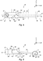
- the Figures 5 to 12 illustrate a locking system 8 according to a first possible embodiment.
- the locking elements 9, 10 extend substantially in the direction X.
- the first locking element 9 comprises a first articulation 13 mounted on the movable cover 6 and having an axis of rotation B perpendicular to the direction X, thereby allowing the first locking element 9 to rotate relative to the movable cover 6 in a plane of rotation.
- rotation (X, Y) perpendicular to the plane of the figure, between a locking position in which the two attachment members 11, 12 are hung together and an unlocking position in which the two attachment members 11, 12 are released one of the other.
- the axis of rotation B of the first locking member 9 could form an angle with respect to the plane of the figure which is a plane substantially tangential to the surface of the movable cover 6.
- the plane of rotation of the first attachment member 11 would then no longer perpendicular to the plane of the figure. It is not excluded to provide the axis of rotation B perpendicular to the plane of the figure, that is to say extending in a radial direction of the nacelle, although this arrangement may have in the radial direction a larger footprint than the first embodiment presently described.
- the first locking element 9 comprises a rear end portion 44 having a hole 43 traversed by the axis B.
- the rear end portion 44 has a greater thickness than the rest of the first locking element 9.
- the figure 5 illustrates a view from above and the figure 6 a side view of the two locking elements 9, 10 in the locked position when the movable cover 6 is in the closed position.
- the first locking element 9 comprises a return spring (not shown) able to exert a restoring force to bring back the first locking element 9 towards the second locking element 10.
- the arrow F has the action of the return spring on the first locking element 9.
- the two attachment members 11, 12 are in contact and lock each other so as not to be detached, even if there are strong vibrations.
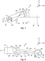
- the figure 7 illustrates a view from above and the figure 8 a side view of the two locking elements 9, 10 during the movement of reclosing the movable cover 6.
- the first locking element 9 slides along the first hooking member 11 of the second locking element 10, as previously described, causing the first locking element 9 about the axis B which is parallel to the axis Z, in this example, and in the opposite direction to that of the second locking element 10 (clockwise on the figure 8 ).
- the two attachment members 11, 12 move away from each other in the direction X and the direction Y.
- the locking system 8 comprises deflection means 16 for deflecting the path of the first attachment member 11 of the first locking element 9 relative to the second attachment member 12 of the second locking element 10 when the movable cover 6 translate from its closed position to its closed position, as illustrated on the figure 7 .
- the path deflection means 16 comprise an inclined wall 18 with respect to a longitudinal axis E of the second locking element 10.
- the inclined wall 18 is formed on the second locking element 10. It is perpendicular to a flat surface 42 of the second locking element 10.
- a hinge 17 is provided on the second locking element 10.
- the second hinge 17 has an axis C perpendicular to the axis B allowing the rotation of the second locking element 10 with respect to the first locking element 9 in the plane (X, Z) between a locking position in which the two locking elements 9, 10 are substantially aligned in the X direction ( Figures 5 and 6 ) and an unlocking position in which the second locking element 10 is inclined with respect to the first locking element 9 ( Figures 9 and 10 ).
- the front end 14 of the first locking element 9 is intended to slide along the inclined wall 18 while pushing it to rotate it from the locking position to the unlocking position.
- the portion of the front end 14 which slides along the inclined wall 18 is schematically represented by a wedge, but it is understood that to limit the friction and wear of this end portion, it can be provided a part rounded or provided with a roller or a ball bearing for rolling on the inclined wall 18.
- the path deflection means 16 comprise a return spring (not shown) tending to keep the second locking element 10 in the locking position, that is to say aligned in the X direction.
- the arrow G represents the action of the return spring on the second locking element 10.
- This movement causes the rotation of the second locking element 10 with respect to the first locking element 9 in the plane (Z, X) (counterclockwise on the figure 7 ), around the C axis.
- the return spring 16 of the path deflection means 16 has a stiffness adapted to not hinder the reclosure movement of the movable cover 6, that is to say, not to prevent the pivoting of the second element of locking 10 during this reclosure movement when the first locking member 9 bears on the inclined wall 18 by sliding along it.
- the first locking member 9 and the second locking member 10 are offset relative to each other in the (X, Z) plane.
- the front ends 14, 15 of the locking elements 9, 10 are no longer superimposed.
- the first locking element 9 has pivoted about the axis B (counterclockwise on the figure 10 ) to end up almost in the same plane (X, Z) as that of the second locking element 10.
- the locking elements 9, 10 can then be moved away from one another by translational movement of the movable cover 6 towards a direction opposite to the fixed cover 5 (towards the rear).
- the Figures 11 and 12 represent the locking elements 9, 10 remote when the movable cover 6 is in the open position.
- the second locking element 10 pivots about the axis C towards the first locking element 9 to return to its initial position, that is to say parallel to the X direction.
- the locking elements 9, 10 are substantially aligned with each other in the X direction.
- the thrust reverser of the turbojet engine 2 can thus be activated.
- first locking element 9 can be mounted on the fixed cover 5 and the second locking element 10 can be mounted on the movable cover 6.
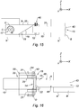
- the figure 13 is a top view of a locking system 8 according to another embodiment when the movable cover 6 is in the closed position.
- the figure 14 represents this locking system 8 profile view.
- the first locking element 9 comprises the first articulation 13 and the second articulation 17.
- the first locking element 9 is connected to the movable cover 6 via the second articulation 17.
- the second articulation 17 is associated with a return spring for bringing back the first locking element 9 aligned with the second locking element 10.
- the second locking element 10 is fixed to the fixed cover 5 and is stationary relative to this fixed cover 5.
- the axis B is perpendicular to the axis C.
- the second locking element 10 comprises the inclined wall 18 as described above.
- the first locking element 9 comprises a rear end portion 44 having an orifice 43 traversed by the axis B.
- the rear end portion 44 also has a second port (not shown).
- the movable cover 6 comprises an orifice 45.
- the axis C of the second articulation 17 passes through the orifice 45 of the movable cover 6 and the second orifice of the rear end portion 44 of the first locking element 9.
- the first locking element 9 is thus movable in two degrees of freedom with respect to the second locking element 10 which is fixed.
- the assembly formed by the two attachment members 11, 12 has two degrees of freedom relative to the covers 5, 6.
- the first pivoting fastening member 11 makes a reclosing path, from the closed position to the reclosing position of the movable cover 6, which is different from the opening path which it follows from the reclosing position to the open position of the movable cover 6.
- the opening path is not performed in a path in the opposite direction to that followed by the reclosing path.
- the second locking element 10 may comprise the first articulation 13 and the second articulation 17. The second locking element 10 is then connected to the fixed cover 5 via the second articulation 17.
- the first locking element 9 can be mounted on the fixed cover 5 and the second locking element 10 mounted on the movable cover 6.
- the locking system 8 may comprise a set of sensors 46 formed by two inductive proximity sensors installed in the vicinity of the longitudinal portion 31 of the first locking element 9, with for example a sensor mounted on the first locking element 9 and a another sensor mounted on the second locking element 10, so as to detect the locking of the first attachment member 11 of the first locking element 9 (movable cover 5 in the closed position) by the corresponding position of the two sensors which are then very close to each other.
- the locking system 8 comprises a locking means (not shown) for locking the locking elements 9, 10 in the locked position when the sensor assembly 46 has detected the locking of the first attachment member 11 of the first locking element 9.
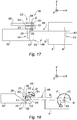
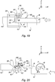
- FIGS. 16 to 25 illustrate another embodiment, wherein the path deflection means 16 includes in particular a pivoting cam.
- the second locking element 10 is fixed on the fixed cover 5.
- the first locking element 9 is mounted on the movable cover 6 and comprises the first articulation 13 making it mobile in rotation relative thereto around the axis B.
- the front end 14 of the first locking element 9 slides along an inclined wall 20 formed on the second locking element 10. In other words, the first attachment member 11 rises the inclined wall 20.
- the front part 32 of the first attachment member 11 of the first locking element 9 comprises an inclined wall 47 which can be provided very slightly concave and substantially parallel to the inclined wall 20 of the second locking element 10 to have a non-angular support of the first organ fastening 11 on the inclined wall 20 and thus limit the mutual wear of these parts during the movement of reclosing the movable cover 6.
- the first locking element 9 is similar to that of the previous embodiment. It likewise comprises a first hinge 13 mounted on the movable hood 6 and having an axis of rotation B perpendicular to the direction X, and also comprises a return spring bringing it back to the locking position.
- the axis of rotation B of the first locking element 9 could form an angle with respect to the plane of the figure which is a plane substantially tangential to the surface of the movable cover 6.
- the path deviation means 16 comprise at least one cam 21 pivotally mounted on a support 55 integral with a structure, here the fixed cover 5, on which the second locking element 10 is integrally mounted.
- This support 55 extends for example along a lateral face 23 of the second locking element 10, as shown in FIG. figure 16 .
- the path deflection means 16 further comprise a guide member 22, for example formed by a cylindrical rod or a pin, provided at the front end 14 of the first locking element 9.
- This guide member 22 may be provided mounted rotatable on its axis relative to the body of the first locking element 9.
- a rotating cylindrical rod 22 may be mounted on bearings (not shown) installed on the front end 14.
- rod guide 22 protrudes from at least one of the lateral sides 48 of the first locking element 9.
- the cam 21 is rotatable about a pivot axis 53 which extends in a direction D for example parallel to that of the axis B around which pivots the first locking member 9.
- the path deflection means 16 comprise a return spring for maintaining the cam 21 in the rest position.
- the guide rod 22 is positioned on the upper face 49 of the first locking element 9.
- the figure 16 illustrates an embodiment in which the path deflection means 16 comprise two cams 21, and the Figures 17 to 23 illustrate a embodiment in which the path deflection means 16 comprise a single cam 21.
- cams 21 The presence of two cams 21 implies that the guide rod 22 projects from the two lateral sides 48 of the first locking element 9. This redundancy provides additional security in the very hypothetical case of rupture of one of the two cams. Safety can nevertheless be judged satisfactory with a single cam 21.
- each cam 21 may comprise an arm 54 integral with the pivot axis 53 of the cam, which abuts against a pin fixed to the fixed hood 5.
- an arm 54 integral with the pivot axis 53 of the cam, which abuts against a pin fixed to the fixed hood 5.
- a pin fixed to the fixed hood 5.
- FIGS 16 and 17 such a pin is mounted on each support 55 secured to the fixed hood 5, and is shown schematically by a line.
- the cam 21 comprises a first portion 50 and a second portion 51 inclined relative to the first portion 50. These two portions 50, 51 are formed on either side of the pivot axis 53.
- the first portion 50 is longer than the second portion 51.
- the presence of a second portion 51 of the cam 21 is not essential, its utility mainly relates to an embodiment with reference to the figures 24 and 25 .
- the pivot axis 53 of the cam 21 may be positioned above the inclined wall 20, between the latter and the second attachment member 12 of the second locking element 10 (not shown).
- the pivot axis 53 of the cam 21 is positioned above the second attachment member 12 of the second locking element 10, as shown in FIGS. Figures 17 to 23 , and in such a way that the front end of the first portion 50 of the cam 21 slightly protrudes forwardly of the guide rod 22 when the locking elements 9, 10 are locked to one another ( figure 18 ).
- This arrangement allows the cam 21 to pivot rapidly towards its rest position in abutment for the automatic unlocking of the locking elements 9, 10 during the closing of the movable cover ( figure 21 ), despite the very short stroke (a few millimeters) of the reclosing motion.
- the cam 21 is positioned near the guide rod 22 so that the inner face 24 of the cam 21 is in contact with the guide rod 22 of the first locking element 9 when the movable cover 6 is in the position of closing. More specifically, it is the inner face 24 of the first portion 50 of the cam 21 which is in contact with the guide rod 22.
- the cam 21 is in the bearing position against the first locking element 9, under the effect of the return spring of the cam. More specifically, the inner face 24 of the cam 21 bears on the guide rod 22 of the first locking element 9.
- the first attachment member 11 of the first locking element 9 is engaged in a cavity 52 formed in the second locking element 10 and positioned between the second attachment member 12 and the wall inclined 20 of the second locking element 10.
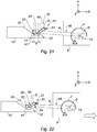
- the inclined wall 47 of the first locking element 9 begins to slide along the inclined wall 20 of the second locking element 10, that is to say that the first attachment member 11 of the first locking element 9 goes up the inclined wall 20 of the second locking element 10.
- this displacement causes a more or less sensitive rotational movement of the first locking element 9 around the axis B in a direction opposite to the second locking element 10 (clockwise direction). figure 20 ).
- the guiding member 22 of the first locking element 9 slides or rolls along the inside face 24 of the first portion 50 of the cam 21.
- This displacement can cause the cam 21 to pivot slightly in a direction opposite to the second element lock 10 (clockwise from the figure 20 ), depending on the profile of the cam and the profile of the inclined wall 20 of the second locking element 10 which determines the path of the first attachment member 11.
- the first attachment member 11 of the first locking element 9 is in a position of maximum advancement on the inclined wall 20 of the second locking element 10.
- the guiding member 22 of the first locking element 9 has disengaged with respect to the inner face 24 of the first portion 50 of the cam 21, which has allowed the cam to pivot towards the second locking element 10 ( counter clockwise of the figure 21 ) to find its rest position in abutment, the first portion 50 of the cam then being inclined downwards.
- the guide member 22 is then found in front of the outer wall 25 of the cam 21.
- the inclined wall 47 of the first locking element 9 slides along the inclined wall 20 of the second locking element 10 towards the second attachment member 12 of the second locking element 10 until the guide member 22 comes in contact with the outer face 25 of the first portion 50 of the cam 21.
- the guide member 22 then slides on the outer face 25 of the first portion 50 of the cam 21 without the cam pivots. Indeed, the guide member 22 of the first locking element 9 exerts a support which tends to rotate the cam 21 in the counterclockwise direction of the figure 22 , while the cam is in its rest position abutting in this direction.
- the outer face 25 of the first portion 50 thus serves as a guide surface of the guide member 22 when opening the movable cover from its closed position.
- the attachment member of the first locking element 9 is guided by the cam 21 to make an opening path which is different from the path made during the reclosing of the movable cover 6.
- the stroke d of the first attachment member 11 of the first locking element 9 (or movement during the reclosing of the movable cover 6) and the stiffness of the seal 30 are adapted so as not to risk inadvertent unlocking of the fastening members 11, 12 in the event of a fortuitous event such as strong vibrations or shocks (foreign objects, loss of fan blade, bursting of a turbine disc ...) that would suffer the turbojet 2.
- the stroke d may be greater than 3 mm, or even greater than 5 mm.
- the seal 30 must maintain a minimum stiffness.
- the locking system 8 comprises a safety device for mitigating the consequences of a hypothetical inadvertent reclosing of the movable cowl.
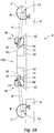
- the safety device comprises a jack 26, positioned near the cam 21 and which comprises a movable rod 27 able to occupy an extended position in which the rod 27 is out of the cylinder 26 to come in close proximity to the cam. an upper face 28 of the second portion 51 of the cam 21 ( figures 24 and 25 ).
- This deployed position is activated following the locking of the fastening members 11, 12, and its deactivation is controlled by the control of the opening of the movable cover 6.
- the rod 27 is fit to serve as a stop to prevent a significant rotation of the cam 21 in case of reclosing the movable cover.
- the rod 27 can further occupy a retracted position (not shown) in which it is retracted into the jack 26 and can not serve as a stop with respect to the cam 21.
- the displacement (in the forward direction) of the guide member 22 of the first locking element 9 first slightly rotates the cam 21 in the clockwise direction on the figure 25 . Then the cam 21 pivots slightly in the other direction (counterclockwise) towards the second locking element 10 as the guide 22 passes under the end of the cam 21, to abut against the rod 27 of the cylinder 26, that is to say, to return almost to its initial position.
- the safety mechanism does not exert any force on the cam 21 or on other parts, apart from the extremely unlikely case of a reclosing of the non-controlled movable cover 6.
- This security mechanism can therefore be simple, requiring little maintenance and a long life.
- the control of the opening of the movable cowl 6 first causes a controlled reclosing of the cover 6.
- the rod 27 of the jack 26 must then be retracted before the movable cowl 6 moves from its closed position to its opening position, so as not to prevent the unlocking of the attachment members 11, 12.
- the control order of the opening of the cover 6 can also be used to control the retraction of the rod 27.
- the locking system 8 may comprise a locking means for locking the locking elements 9, 10 in the locked position when a locking detection system (for example a set of sensors 46 as described above) has detected the locking of the first attachment member 11 of the first locking element 9.
- a locking detection system for example a set of sensors 46 as described above
- the output (extended position) of the rod 27 of the jack 26 can then be controlled by the control system of the locking means, as soon as the locking detection system detects the transition from an unlocked state to the locked state.
- the rod 27 of the jack 26 preferably comprises a position sensor to inform the control system of the locking means and to verify the correct match between the position of the rod 27 of the jack 26 and the state of the locking means.
- the energy to move the rod 27 of the cylinder 26 may be very low, since the latter has no effort to exert on a part.
- the jack 26 may be a small size electric jack.
- the path deflection means 16 comprise two cams 21 as described with reference to FIG. figure 16 it is possible to provide a bridging rigidly connecting the two pivot axes 53 of the cams to make the two cams integral in motion from one another.
- the geometry of this bridging for example U-shaped, will be provided to not interfere with the passage of the first attachment member 11 between the two cams.
- This arrangement makes it possible to have only one safety device such as a jack 26 to prevent rotation of the two cams 21 in the event of uncontrolled reclosing of the movable cowl 6.
- maintaining the cam 21 by the rod 27 of the cylinder 26 is performed at the second portion 51 of the cam.
- the second portion 51 of the cam can be omitted, and the jack 26 can be positioned so that in case of uncontrolled reclosing of the movable cover 6, the rod 27 of the jack can act as a stop on the arm 54 secured to the pivot axis 53 of the cam to prevent significant rotation of the cam.
- first pivoting locking element 9 is not necessarily mounted on the movable cover 6.
- first locking element 9 can be pivotally mounted on the fixed hood 5 or on another fixed structure of the nacelle, the second locking element 10 as well as the path deflection means 16 then being provided integral in displacement of the movable hood 6.
- the various embodiments of the locking system 8 are used to lock a cover 6 movable in translation on the nacelle 1 relative to a fixed structure 5 constituted by a fixed hood of the nacelle, the thrust reverser system then being of the grid type.
- a thrust reverser system is however not limited to this type of inverter, the invention also applies to reversers of thrust of the door type.
- a movable cowl does not perform a translation but a rotation relative to an axis of rotation so that the cowl itself constitutes a deflector to deflect both the secondary flow and the primary flow globally forward to the outside of the nacelle.
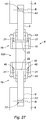
- the invention therefore also applies to a door thrust reverser system, comprising two movable hoods 6 pivotable about respectively two axes of different rotations, as shown in FIG. figure 26 .
- "Mobile hoods” 6 are also called “moving doors”. They can be only two in number as in the example shown, but architectures with more than two doors also exist, for example four doors.
- the two movable hoods 6 are positioned in opposition to a longitudinal axis A of the thrust reverser system.
- the thrust reverser system comprises two locking systems 8 positioned on the nacelle 1 and in opposition with respect to the longitudinal axis A.
- Each locking system 8 comprises two first locking elements 9 mounted on two different covers or movable doors 6 and two second locking elements mounted back to back on a fixed structure 5 of the nacelle 1.
- the two second locking elements 10 may be made in the form of separate parts, or may constitute two parts of a common part 100 intended to cooperate with the first two locking elements 9 mounted on two different moving covers 6, as shown on the figures 26 and 27 .
- the first two locking elements 9 are each positioned at a front corner 56 of the movable cover 6 concerned.
- Each common part 100 comprising two second locking elements 10 is positioned on a circumferential wall 57 of the fixed structure 5 of the nacelle 1. In the embodiment shown, a single common part 100 is visible, but it should be understood that two common parts 100 are diametrically opposed on the circumferential wall 57 with respect to the longitudinal axis A.
- the first and second locking elements 9, 10 of each locking system 8 associated with a movable cover 6 are able to be locked and unlocked with respect to each other in order to lock the movable cover 6 on the fixed structure 5 in the closed position of the movable hood.
- a controlled displacement of each mobile cowl 6 from its closed position to a re-closing position triggers the unlocking of the first and second locking elements 9, 10 of each locking system 8 associated with the moving cowl 6.
- the reclosing of a movable cowl 6 causes the two first locking elements 9 of the same movable cowl 6 to move in the direction of the longitudinal axis A, during a rotational movement of the movable cowl 6 directed towards this axis.
- a locking system 8 is structurally and functionally similar to any one of the locking systems 8 illustrated on the Figures 16 to 25 .
- the figures 27 and 28 describe more precisely an example of a locking system 8 that is structurally and functionally similar to that described with reference to FIG. figure 16 .
- Each first locking element 9 comprises a first articulation 13 having an axis of rotation B allowing a rotation of the first locking element 9 between a locking position and an unlocking position relative to the second locking element 10, during the movement of the hood mobile 6 between a closed position and a closed position of the latter.
- the first locking element 9 comprises a return spring adapted to exert a restoring force to bring the first locking element 9 towards the second locking element 10.
- the first locking elements 9 each comprise a first attachment member 11, as illustrated in FIG. figure 28 , can be a hook.
- the common part 100 comprising two second locking elements 10 comprises two second hooking members 12 which may be hooks, opposite to each other and each cooperating with a first attachment member 11 separate.
- Each second locking element 10 comprises a path deflection means 16 adapted so that the path followed by each first attachment member 11 relative to the second attachment member 12 takes a different path between a reclosing phase when the two movable covers 6 move from their closed position to their respective reclosure position and an opening phase when the movable covers 6 move from their closed position to their open position.
- the two path deflection means 16 provided on the common part 100 of a locking system 8 are opposite to each other.
- the two path deflection means 16 each comprise an inclined wall 20 formed on the corresponding second locking element 10.
- the two inclined walls 20 have an opposite orientation.
- the front end 14 of a first locking element 9 is intended to slide along the corresponding inclined wall 20, during the reclosure movement causing a translation of the first attachment member 11 of the first locking element 9.
- the path deflection means 16 each comprise two cams 21 as previously described.
- only one cam 21 may be provided, in the same way as in the embodiment with reference to FIG. figure 17 .
Landscapes
- Engineering & Computer Science (AREA)
- Chemical & Material Sciences (AREA)
- Combustion & Propulsion (AREA)
- Mechanical Engineering (AREA)
- General Engineering & Computer Science (AREA)
- Aviation & Aerospace Engineering (AREA)
- Structures Of Non-Positive Displacement Pumps (AREA)
- Superstructure Of Vehicle (AREA)
- Wind Motors (AREA)
- Control Of Turbines (AREA)
Applications Claiming Priority (1)
| Application Number | Priority Date | Filing Date | Title |
|---|---|---|---|
| FR1753283A FR3065260B1 (fr) | 2017-04-14 | 2017-04-14 | Systeme inverseur de poussee pour turboreacteur |
Publications (2)
| Publication Number | Publication Date |
|---|---|
| EP3388657A1 true EP3388657A1 (de) | 2018-10-17 |
| EP3388657B1 EP3388657B1 (de) | 2020-04-22 |
Family
ID=59930412
Family Applications (1)
| Application Number | Title | Priority Date | Filing Date |
|---|---|---|---|
| EP18167316.1A Active EP3388657B1 (de) | 2017-04-14 | 2018-04-13 | Vorrichtung und verfahren zur entriegelung einer gondel eines turboreaktors |
Country Status (4)
| Country | Link |
|---|---|
| US (1) | US10914267B2 (de) |
| EP (1) | EP3388657B1 (de) |
| CN (1) | CN108773493B (de) |
| FR (1) | FR3065260B1 (de) |
Cited By (1)
| Publication number | Priority date | Publication date | Assignee | Title |
|---|---|---|---|---|
| FR3123388A1 (fr) * | 2021-05-31 | 2022-12-02 | Safran Nacelles | Ensemble inverseur de poussée pour turboréacteur |
Families Citing this family (3)
| Publication number | Priority date | Publication date | Assignee | Title |
|---|---|---|---|---|
| FR3094698B1 (fr) * | 2019-04-02 | 2022-09-09 | Safran Aircraft Engines | Manche d’entree d’air pour une nacelle d’un ensemble propulsif d’aeronef |
| US11268406B2 (en) * | 2019-08-12 | 2022-03-08 | The Boeing Company | Movement-limiting device for a turbine engine and associated method |
| EP4177457A1 (de) | 2021-11-03 | 2023-05-10 | Goodrich Actuation Systems Limited | Schlosspositionserfassung |
Citations (4)
| Publication number | Priority date | Publication date | Assignee | Title |
|---|---|---|---|---|
| FR2890644A1 (fr) * | 2005-09-15 | 2007-03-16 | Aircelle Sa | Dispostif d'accrochage a autoverrouillage dynamique |
| US20100264676A1 (en) * | 2009-04-21 | 2010-10-21 | Spirit AeroSystems, Inc, | Tertiary lock for pivot door thrust reverser |
| US20140270935A1 (en) * | 2013-03-14 | 2014-09-18 | Woodward Hrt, Inc. | Engine Thrust Reverser Lock |
| US20170016412A1 (en) * | 2014-03-31 | 2017-01-19 | Aircelle | Thrust reverser of a turbojet engine nacelle, comprising control cylinders of movable cowls and a variable secondary nozzle |
Family Cites Families (14)
| Publication number | Priority date | Publication date | Assignee | Title |
|---|---|---|---|---|
| FR2711733B1 (fr) * | 1993-10-22 | 1996-01-26 | Hurel Dubois Avions | Inverseur de poussée à portes pour moteur d'avion à réaction équipées d'un volet auxiliaire. |
| DE69514224T2 (de) | 1995-09-13 | 2000-08-10 | Societe De Construction Des Avions Hurel-Dubois (S.A.), Meudon-La-Foret | Elektrohydraulische Schubumkehrvorrichtung mit zwei Klappen |
| FR2765916B1 (fr) * | 1997-07-10 | 1999-08-20 | Hispano Suiza Sa | Inverseur de poussee a resistance amelioree aux impacts |
| FR2823259B1 (fr) * | 2001-04-05 | 2003-06-27 | Hispano Suiza Sa | Systeme de verrouillage synchronise des portes d'un inverseur de poussee |
| FR2920137B1 (fr) * | 2007-08-20 | 2009-09-18 | Aircelle Sa | Fixation d'une structure d'une nacelle de turboreacteur par bride couteau/gorge renforcee |
| DE102008045851A1 (de) * | 2008-09-05 | 2010-03-11 | Rolls-Royce Deutschland Ltd & Co Kg | Vorrichtung zum Öffnen und Schließen einer Schubumkehrertür eines Strahltriebwerks |
| FR2952681B1 (fr) * | 2009-11-18 | 2017-10-06 | Aircelle Sa | Inverseur de poussee |
| FR2959532B1 (fr) * | 2010-04-30 | 2013-01-04 | Aircelle Sa | Nacelle de turboreacteur |
| FR2960917B1 (fr) * | 2010-06-03 | 2012-05-18 | Aircelle Sa | Inverseur de poussee a section de tuyere variable verrouillable |
| FR2970521B1 (fr) | 2011-01-17 | 2013-01-04 | Aircelle Sa | Inverseur de poussee pour turboreacteur d'aeronef a nombre de verrous reduit |
| FR2981989B1 (fr) * | 2011-10-31 | 2013-11-01 | Aircelle Sa | Inverseur de poussee a grilles mobiles et capot mobile monobloc |
| FR2982324B1 (fr) * | 2011-11-09 | 2013-11-15 | Aircelle Sa | Inverseur de poussee a portes jumelles |
| FR2998619B1 (fr) * | 2012-11-28 | 2021-05-07 | Aircelle Sa | Verrou actif avec assistance de mobilisation et inverseur de poussee incorporant un tel verrou |
| DE102014104921A1 (de) * | 2014-04-07 | 2015-10-08 | Airbus Operations Gmbh | Haltesystem für eine bewegliche Komponente |
-
2017
- 2017-04-14 FR FR1753283A patent/FR3065260B1/fr active Active
-
2018
- 2018-04-13 EP EP18167316.1A patent/EP3388657B1/de active Active
- 2018-04-16 US US15/953,604 patent/US10914267B2/en active Active
- 2018-04-16 CN CN201810338078.2A patent/CN108773493B/zh active Active
Patent Citations (4)
| Publication number | Priority date | Publication date | Assignee | Title |
|---|---|---|---|---|
| FR2890644A1 (fr) * | 2005-09-15 | 2007-03-16 | Aircelle Sa | Dispostif d'accrochage a autoverrouillage dynamique |
| US20100264676A1 (en) * | 2009-04-21 | 2010-10-21 | Spirit AeroSystems, Inc, | Tertiary lock for pivot door thrust reverser |
| US20140270935A1 (en) * | 2013-03-14 | 2014-09-18 | Woodward Hrt, Inc. | Engine Thrust Reverser Lock |
| US20170016412A1 (en) * | 2014-03-31 | 2017-01-19 | Aircelle | Thrust reverser of a turbojet engine nacelle, comprising control cylinders of movable cowls and a variable secondary nozzle |
Cited By (3)
| Publication number | Priority date | Publication date | Assignee | Title |
|---|---|---|---|---|
| FR3123388A1 (fr) * | 2021-05-31 | 2022-12-02 | Safran Nacelles | Ensemble inverseur de poussée pour turboréacteur |
| WO2022254141A1 (fr) * | 2021-05-31 | 2022-12-08 | Safran Nacelles | Ensemble inverseur de poussee pour turboreacteur |
| US12078124B2 (en) | 2021-05-31 | 2024-09-03 | Safran Nacelles | Thrust reverser assembly for a turbojet engine |
Also Published As
| Publication number | Publication date |
|---|---|
| CN108773493B (zh) | 2023-06-20 |
| US10914267B2 (en) | 2021-02-09 |
| US20180298844A1 (en) | 2018-10-18 |
| EP3388657B1 (de) | 2020-04-22 |
| FR3065260A1 (fr) | 2018-10-19 |
| CN108773493A (zh) | 2018-11-09 |
| FR3065260B1 (fr) | 2020-10-09 |
Similar Documents
| Publication | Publication Date | Title |
|---|---|---|
| CA2461207C (fr) | Systeme de verrouillage sur un inverseur de poussee a grilles | |
| EP2665911B1 (de) | Schubumkehrvorrichtung für einen flugzeug-turbodüsenmotor mit einer geringeren anzahl von riegeln | |
| EP3388657B1 (de) | Vorrichtung und verfahren zur entriegelung einer gondel eines turboreaktors | |
| CA2379192C (fr) | Systeme de verrouillage de secours pour porte d'inverseur de poussee | |
| CA2678308A1 (fr) | Verin a dispositif de verrouillage integre | |
| FR2960917A1 (fr) | Inverseur de poussee a section de tuyere variable verrouillable | |
| FR2622930A1 (fr) | Capotage pour turboreacteur a double flux | |
| FR2960855A1 (fr) | Nacelle pour turboreacteur avec dispositif de reprise d'efforts circonferentiels | |
| EP1260696A1 (de) | Synchronisierte Verriegelungsvorrichtung für die Klappen einer Schubumkehrvorrichtung | |
| CA2858504A1 (fr) | Porte pour inverseur de poussee a portes | |
| EP3303811B1 (de) | Schubumkehrvorrichtung für flugzeugtriebwerksgondel | |
| EP3126657B1 (de) | System zum verriegeln eines schubumkehrers mit klappen, einschliesslich verriegelungen für eine öffnungszwischenposition | |
| FR2932455A1 (fr) | Dispositif de verin pour systeme de train d'atterrissage d'aeronef. | |
| EP2971730B1 (de) | In eine sperreinrichtung einer schubumkehrvorrichtung integrierte mechanische hemmvorrichtung | |
| CA2882318C (fr) | Ensemble de maintien de l'interface d'un cadre avant d'une nacelle et d'un carter de turboreacteur | |
| EP2188178B1 (de) | Triebwerksgondel zum einbau in ein flugzeug | |
| FR2997925A1 (fr) | Ensemble de guidage pour ensemble unitaire mobile de nacelle pour turboreacteur | |
| WO2015140450A1 (fr) | Dispositif de verrouillage pour un inverseur de poussée à porte | |
| FR3130902A1 (fr) | Nacelle pour ensemble propulsif d’aéronef comprenant un volet pour obturer un évidement de passage d’un organe mécanique | |
| FR3027066A1 (fr) | Inverseur de poussee pour nacelle de turboreacteur d'aeronef et nacelle associee |
Legal Events
| Date | Code | Title | Description |
|---|---|---|---|
| PUAI | Public reference made under article 153(3) epc to a published international application that has entered the european phase |
Free format text: ORIGINAL CODE: 0009012 |
|
| STAA | Information on the status of an ep patent application or granted ep patent |
Free format text: STATUS: THE APPLICATION HAS BEEN PUBLISHED |
|
| AK | Designated contracting states |
Kind code of ref document: A1 Designated state(s): AL AT BE BG CH CY CZ DE DK EE ES FI FR GB GR HR HU IE IS IT LI LT LU LV MC MK MT NL NO PL PT RO RS SE SI SK SM TR |
|
| AX | Request for extension of the european patent |
Extension state: BA ME |
|
| STAA | Information on the status of an ep patent application or granted ep patent |
Free format text: STATUS: REQUEST FOR EXAMINATION WAS MADE |
|
| 17P | Request for examination filed |
Effective date: 20190410 |
|
| RBV | Designated contracting states (corrected) |
Designated state(s): AL AT BE BG CH CY CZ DE DK EE ES FI FR GB GR HR HU IE IS IT LI LT LU LV MC MK MT NL NO PL PT RO RS SE SI SK SM TR |
|
| RIC1 | Information provided on ipc code assigned before grant |
Ipc: F02K 1/76 20060101AFI20191129BHEP |
|
| GRAP | Despatch of communication of intention to grant a patent |
Free format text: ORIGINAL CODE: EPIDOSNIGR1 |
|
| STAA | Information on the status of an ep patent application or granted ep patent |
Free format text: STATUS: GRANT OF PATENT IS INTENDED |
|
| INTG | Intention to grant announced |
Effective date: 20200128 |
|
| GRAS | Grant fee paid |
Free format text: ORIGINAL CODE: EPIDOSNIGR3 |
|
| GRAA | (expected) grant |
Free format text: ORIGINAL CODE: 0009210 |
|
| STAA | Information on the status of an ep patent application or granted ep patent |
Free format text: STATUS: THE PATENT HAS BEEN GRANTED |
|
| AK | Designated contracting states |
Kind code of ref document: B1 Designated state(s): AL AT BE BG CH CY CZ DE DK EE ES FI FR GB GR HR HU IE IS IT LI LT LU LV MC MK MT NL NO PL PT RO RS SE SI SK SM TR |
|
| REG | Reference to a national code |
Ref country code: CH Ref legal event code: EP |
|
| REG | Reference to a national code |
Ref country code: DE Ref legal event code: R096 Ref document number: 602018003886 Country of ref document: DE |
|
| REG | Reference to a national code |
Ref country code: IE Ref legal event code: FG4D Free format text: LANGUAGE OF EP DOCUMENT: FRENCH |
|
| REG | Reference to a national code |
Ref country code: AT Ref legal event code: REF Ref document number: 1260405 Country of ref document: AT Kind code of ref document: T Effective date: 20200515 |
|
| REG | Reference to a national code |
Ref country code: SE Ref legal event code: TRGR |
|
| REG | Reference to a national code |
Ref country code: LT Ref legal event code: MG4D |
|
| REG | Reference to a national code |
Ref country code: NL Ref legal event code: MP Effective date: 20200422 |
|
| PG25 | Lapsed in a contracting state [announced via postgrant information from national office to epo] |
Ref country code: NL Free format text: LAPSE BECAUSE OF FAILURE TO SUBMIT A TRANSLATION OF THE DESCRIPTION OR TO PAY THE FEE WITHIN THE PRESCRIBED TIME-LIMIT Effective date: 20200422 Ref country code: LT Free format text: LAPSE BECAUSE OF FAILURE TO SUBMIT A TRANSLATION OF THE DESCRIPTION OR TO PAY THE FEE WITHIN THE PRESCRIBED TIME-LIMIT Effective date: 20200422 Ref country code: PT Free format text: LAPSE BECAUSE OF FAILURE TO SUBMIT A TRANSLATION OF THE DESCRIPTION OR TO PAY THE FEE WITHIN THE PRESCRIBED TIME-LIMIT Effective date: 20200824 Ref country code: IS Free format text: LAPSE BECAUSE OF FAILURE TO SUBMIT A TRANSLATION OF THE DESCRIPTION OR TO PAY THE FEE WITHIN THE PRESCRIBED TIME-LIMIT Effective date: 20200822 Ref country code: NO Free format text: LAPSE BECAUSE OF FAILURE TO SUBMIT A TRANSLATION OF THE DESCRIPTION OR TO PAY THE FEE WITHIN THE PRESCRIBED TIME-LIMIT Effective date: 20200722 Ref country code: FI Free format text: LAPSE BECAUSE OF FAILURE TO SUBMIT A TRANSLATION OF THE DESCRIPTION OR TO PAY THE FEE WITHIN THE PRESCRIBED TIME-LIMIT Effective date: 20200422 Ref country code: GR Free format text: LAPSE BECAUSE OF FAILURE TO SUBMIT A TRANSLATION OF THE DESCRIPTION OR TO PAY THE FEE WITHIN THE PRESCRIBED TIME-LIMIT Effective date: 20200723 |
|
| REG | Reference to a national code |
Ref country code: AT Ref legal event code: MK05 Ref document number: 1260405 Country of ref document: AT Kind code of ref document: T Effective date: 20200422 |
|
| PG25 | Lapsed in a contracting state [announced via postgrant information from national office to epo] |
Ref country code: LV Free format text: LAPSE BECAUSE OF FAILURE TO SUBMIT A TRANSLATION OF THE DESCRIPTION OR TO PAY THE FEE WITHIN THE PRESCRIBED TIME-LIMIT Effective date: 20200422 Ref country code: RS Free format text: LAPSE BECAUSE OF FAILURE TO SUBMIT A TRANSLATION OF THE DESCRIPTION OR TO PAY THE FEE WITHIN THE PRESCRIBED TIME-LIMIT Effective date: 20200422 Ref country code: HR Free format text: LAPSE BECAUSE OF FAILURE TO SUBMIT A TRANSLATION OF THE DESCRIPTION OR TO PAY THE FEE WITHIN THE PRESCRIBED TIME-LIMIT Effective date: 20200422 Ref country code: BG Free format text: LAPSE BECAUSE OF FAILURE TO SUBMIT A TRANSLATION OF THE DESCRIPTION OR TO PAY THE FEE WITHIN THE PRESCRIBED TIME-LIMIT Effective date: 20200722 |
|
| PG25 | Lapsed in a contracting state [announced via postgrant information from national office to epo] |
Ref country code: AL Free format text: LAPSE BECAUSE OF FAILURE TO SUBMIT A TRANSLATION OF THE DESCRIPTION OR TO PAY THE FEE WITHIN THE PRESCRIBED TIME-LIMIT Effective date: 20200422 |
|
| REG | Reference to a national code |
Ref country code: DE Ref legal event code: R097 Ref document number: 602018003886 Country of ref document: DE |
|
| PG25 | Lapsed in a contracting state [announced via postgrant information from national office to epo] |
Ref country code: CZ Free format text: LAPSE BECAUSE OF FAILURE TO SUBMIT A TRANSLATION OF THE DESCRIPTION OR TO PAY THE FEE WITHIN THE PRESCRIBED TIME-LIMIT Effective date: 20200422 Ref country code: ES Free format text: LAPSE BECAUSE OF FAILURE TO SUBMIT A TRANSLATION OF THE DESCRIPTION OR TO PAY THE FEE WITHIN THE PRESCRIBED TIME-LIMIT Effective date: 20200422 Ref country code: RO Free format text: LAPSE BECAUSE OF FAILURE TO SUBMIT A TRANSLATION OF THE DESCRIPTION OR TO PAY THE FEE WITHIN THE PRESCRIBED TIME-LIMIT Effective date: 20200422 Ref country code: DK Free format text: LAPSE BECAUSE OF FAILURE TO SUBMIT A TRANSLATION OF THE DESCRIPTION OR TO PAY THE FEE WITHIN THE PRESCRIBED TIME-LIMIT Effective date: 20200422 Ref country code: SM Free format text: LAPSE BECAUSE OF FAILURE TO SUBMIT A TRANSLATION OF THE DESCRIPTION OR TO PAY THE FEE WITHIN THE PRESCRIBED TIME-LIMIT Effective date: 20200422 Ref country code: EE Free format text: LAPSE BECAUSE OF FAILURE TO SUBMIT A TRANSLATION OF THE DESCRIPTION OR TO PAY THE FEE WITHIN THE PRESCRIBED TIME-LIMIT Effective date: 20200422 Ref country code: AT Free format text: LAPSE BECAUSE OF FAILURE TO SUBMIT A TRANSLATION OF THE DESCRIPTION OR TO PAY THE FEE WITHIN THE PRESCRIBED TIME-LIMIT Effective date: 20200422 |
|
| PG25 | Lapsed in a contracting state [announced via postgrant information from national office to epo] |
Ref country code: SK Free format text: LAPSE BECAUSE OF FAILURE TO SUBMIT A TRANSLATION OF THE DESCRIPTION OR TO PAY THE FEE WITHIN THE PRESCRIBED TIME-LIMIT Effective date: 20200422 Ref country code: PL Free format text: LAPSE BECAUSE OF FAILURE TO SUBMIT A TRANSLATION OF THE DESCRIPTION OR TO PAY THE FEE WITHIN THE PRESCRIBED TIME-LIMIT Effective date: 20200422 |
|
| PLBE | No opposition filed within time limit |
Free format text: ORIGINAL CODE: 0009261 |
|
| STAA | Information on the status of an ep patent application or granted ep patent |
Free format text: STATUS: NO OPPOSITION FILED WITHIN TIME LIMIT |
|
| 26N | No opposition filed |
Effective date: 20210125 |
|
| PG25 | Lapsed in a contracting state [announced via postgrant information from national office to epo] |
Ref country code: SI Free format text: LAPSE BECAUSE OF FAILURE TO SUBMIT A TRANSLATION OF THE DESCRIPTION OR TO PAY THE FEE WITHIN THE PRESCRIBED TIME-LIMIT Effective date: 20200422 |
|
| PG25 | Lapsed in a contracting state [announced via postgrant information from national office to epo] |
Ref country code: MC Free format text: LAPSE BECAUSE OF FAILURE TO SUBMIT A TRANSLATION OF THE DESCRIPTION OR TO PAY THE FEE WITHIN THE PRESCRIBED TIME-LIMIT Effective date: 20200422 |
|
| PG25 | Lapsed in a contracting state [announced via postgrant information from national office to epo] |
Ref country code: LU Free format text: LAPSE BECAUSE OF NON-PAYMENT OF DUE FEES Effective date: 20210413 |
|
| REG | Reference to a national code |
Ref country code: BE Ref legal event code: MM Effective date: 20210430 |
|
| PG25 | Lapsed in a contracting state [announced via postgrant information from national office to epo] |
Ref country code: LI Free format text: LAPSE BECAUSE OF NON-PAYMENT OF DUE FEES Effective date: 20210430 Ref country code: CH Free format text: LAPSE BECAUSE OF NON-PAYMENT OF DUE FEES Effective date: 20210430 |
|
| PG25 | Lapsed in a contracting state [announced via postgrant information from national office to epo] |
Ref country code: IE Free format text: LAPSE BECAUSE OF NON-PAYMENT OF DUE FEES Effective date: 20210413 |
|
| PG25 | Lapsed in a contracting state [announced via postgrant information from national office to epo] |
Ref country code: BE Free format text: LAPSE BECAUSE OF NON-PAYMENT OF DUE FEES Effective date: 20210430 |
|
| PG25 | Lapsed in a contracting state [announced via postgrant information from national office to epo] |
Ref country code: CY Free format text: LAPSE BECAUSE OF FAILURE TO SUBMIT A TRANSLATION OF THE DESCRIPTION OR TO PAY THE FEE WITHIN THE PRESCRIBED TIME-LIMIT Effective date: 20200422 |
|
| PG25 | Lapsed in a contracting state [announced via postgrant information from national office to epo] |
Ref country code: HU Free format text: LAPSE BECAUSE OF FAILURE TO SUBMIT A TRANSLATION OF THE DESCRIPTION OR TO PAY THE FEE WITHIN THE PRESCRIBED TIME-LIMIT; INVALID AB INITIO Effective date: 20180413 |
|
| PG25 | Lapsed in a contracting state [announced via postgrant information from national office to epo] |
Ref country code: MK Free format text: LAPSE BECAUSE OF FAILURE TO SUBMIT A TRANSLATION OF THE DESCRIPTION OR TO PAY THE FEE WITHIN THE PRESCRIBED TIME-LIMIT Effective date: 20200422 |
|
| PG25 | Lapsed in a contracting state [announced via postgrant information from national office to epo] |
Ref country code: TR Free format text: LAPSE BECAUSE OF FAILURE TO SUBMIT A TRANSLATION OF THE DESCRIPTION OR TO PAY THE FEE WITHIN THE PRESCRIBED TIME-LIMIT Effective date: 20200422 |
|
| PG25 | Lapsed in a contracting state [announced via postgrant information from national office to epo] |
Ref country code: MT Free format text: LAPSE BECAUSE OF FAILURE TO SUBMIT A TRANSLATION OF THE DESCRIPTION OR TO PAY THE FEE WITHIN THE PRESCRIBED TIME-LIMIT Effective date: 20200422 |
|
| PGFP | Annual fee paid to national office [announced via postgrant information from national office to epo] |
Ref country code: DE Payment date: 20250417 Year of fee payment: 8 |
|
| PGFP | Annual fee paid to national office [announced via postgrant information from national office to epo] |
Ref country code: IT Payment date: 20250430 Year of fee payment: 8 |
|
| PGFP | Annual fee paid to national office [announced via postgrant information from national office to epo] |
Ref country code: FR Payment date: 20250422 Year of fee payment: 8 |
|
| PGFP | Annual fee paid to national office [announced via postgrant information from national office to epo] |
Ref country code: SE Payment date: 20250423 Year of fee payment: 8 |
|
| PGFP | Annual fee paid to national office [announced via postgrant information from national office to epo] |
Ref country code: GB Payment date: 20260327 Year of fee payment: 9 |