EP3388739B1 - Laserkopflampe für fahrzeug und fahrzeug - Google Patents
Laserkopflampe für fahrzeug und fahrzeug Download PDFInfo
- Publication number
- EP3388739B1 EP3388739B1 EP18163989.9A EP18163989A EP3388739B1 EP 3388739 B1 EP3388739 B1 EP 3388739B1 EP 18163989 A EP18163989 A EP 18163989A EP 3388739 B1 EP3388739 B1 EP 3388739B1
- Authority
- EP
- European Patent Office
- Prior art keywords
- lamp
- lamp module
- modules
- processor
- module group
- Prior art date
- Legal status (The legal status is an assumption and is not a legal conclusion. Google has not performed a legal analysis and makes no representation as to the accuracy of the status listed.)
- Active
Links
Images




Classifications
-
- F—MECHANICAL ENGINEERING; LIGHTING; HEATING; WEAPONS; BLASTING
- F21—LIGHTING
- F21S—NON-PORTABLE LIGHTING DEVICES; SYSTEMS THEREOF; VEHICLE LIGHTING DEVICES SPECIALLY ADAPTED FOR VEHICLE EXTERIORS
- F21S41/00—Illuminating devices specially adapted for vehicle exteriors, e.g. headlamps
- F21S41/10—Illuminating devices specially adapted for vehicle exteriors, e.g. headlamps characterised by the light source
- F21S41/14—Illuminating devices specially adapted for vehicle exteriors, e.g. headlamps characterised by the light source characterised by the type of light source
- F21S41/16—Laser light sources
-
- B—PERFORMING OPERATIONS; TRANSPORTING
- B60—VEHICLES IN GENERAL
- B60Q—ARRANGEMENT OF SIGNALLING OR LIGHTING DEVICES, THE MOUNTING OR SUPPORTING THEREOF OR CIRCUITS THEREFOR, FOR VEHICLES IN GENERAL
- B60Q1/00—Arrangement of optical signalling or lighting devices, the mounting or supporting thereof or circuits therefor
- B60Q1/02—Arrangement of optical signalling or lighting devices, the mounting or supporting thereof or circuits therefor the devices being primarily intended to illuminate the way ahead or to illuminate other areas of way or environments
- B60Q1/04—Arrangement of optical signalling or lighting devices, the mounting or supporting thereof or circuits therefor the devices being primarily intended to illuminate the way ahead or to illuminate other areas of way or environments the devices being headlights
- B60Q1/14—Arrangement of optical signalling or lighting devices, the mounting or supporting thereof or circuits therefor the devices being primarily intended to illuminate the way ahead or to illuminate other areas of way or environments the devices being headlights having dimming means
- B60Q1/1415—Dimming circuits
-
- B—PERFORMING OPERATIONS; TRANSPORTING
- B60—VEHICLES IN GENERAL
- B60Q—ARRANGEMENT OF SIGNALLING OR LIGHTING DEVICES, THE MOUNTING OR SUPPORTING THEREOF OR CIRCUITS THEREFOR, FOR VEHICLES IN GENERAL
- B60Q1/00—Arrangement of optical signalling or lighting devices, the mounting or supporting thereof or circuits therefor
- B60Q1/0017—Devices integrating an element dedicated to another function
- B60Q1/0023—Devices integrating an element dedicated to another function the element being a sensor, e.g. distance sensor, camera
-
- F—MECHANICAL ENGINEERING; LIGHTING; HEATING; WEAPONS; BLASTING
- F21—LIGHTING
- F21S—NON-PORTABLE LIGHTING DEVICES; SYSTEMS THEREOF; VEHICLE LIGHTING DEVICES SPECIALLY ADAPTED FOR VEHICLE EXTERIORS
- F21S41/00—Illuminating devices specially adapted for vehicle exteriors, e.g. headlamps
- F21S41/10—Illuminating devices specially adapted for vehicle exteriors, e.g. headlamps characterised by the light source
- F21S41/14—Illuminating devices specially adapted for vehicle exteriors, e.g. headlamps characterised by the light source characterised by the type of light source
- F21S41/18—Combination of light sources of different types or shapes
-
- B—PERFORMING OPERATIONS; TRANSPORTING
- B60—VEHICLES IN GENERAL
- B60Q—ARRANGEMENT OF SIGNALLING OR LIGHTING DEVICES, THE MOUNTING OR SUPPORTING THEREOF OR CIRCUITS THEREFOR, FOR VEHICLES IN GENERAL
- B60Q1/00—Arrangement of optical signalling or lighting devices, the mounting or supporting thereof or circuits therefor
- B60Q1/02—Arrangement of optical signalling or lighting devices, the mounting or supporting thereof or circuits therefor the devices being primarily intended to illuminate the way ahead or to illuminate other areas of way or environments
- B60Q1/04—Arrangement of optical signalling or lighting devices, the mounting or supporting thereof or circuits therefor the devices being primarily intended to illuminate the way ahead or to illuminate other areas of way or environments the devices being headlights
-
- B—PERFORMING OPERATIONS; TRANSPORTING
- B60—VEHICLES IN GENERAL
- B60Q—ARRANGEMENT OF SIGNALLING OR LIGHTING DEVICES, THE MOUNTING OR SUPPORTING THEREOF OR CIRCUITS THEREFOR, FOR VEHICLES IN GENERAL
- B60Q1/00—Arrangement of optical signalling or lighting devices, the mounting or supporting thereof or circuits therefor
- B60Q1/02—Arrangement of optical signalling or lighting devices, the mounting or supporting thereof or circuits therefor the devices being primarily intended to illuminate the way ahead or to illuminate other areas of way or environments
- B60Q1/04—Arrangement of optical signalling or lighting devices, the mounting or supporting thereof or circuits therefor the devices being primarily intended to illuminate the way ahead or to illuminate other areas of way or environments the devices being headlights
- B60Q1/06—Arrangement of optical signalling or lighting devices, the mounting or supporting thereof or circuits therefor the devices being primarily intended to illuminate the way ahead or to illuminate other areas of way or environments the devices being headlights adjustable, e.g. remotely-controlled from inside vehicle
- B60Q1/08—Arrangement of optical signalling or lighting devices, the mounting or supporting thereof or circuits therefor the devices being primarily intended to illuminate the way ahead or to illuminate other areas of way or environments the devices being headlights adjustable, e.g. remotely-controlled from inside vehicle automatically
- B60Q1/085—Arrangement of optical signalling or lighting devices, the mounting or supporting thereof or circuits therefor the devices being primarily intended to illuminate the way ahead or to illuminate other areas of way or environments the devices being headlights adjustable, e.g. remotely-controlled from inside vehicle automatically due to special conditions, e.g. adverse weather, type of road, badly illuminated road signs or potential dangers
-
- B—PERFORMING OPERATIONS; TRANSPORTING
- B60—VEHICLES IN GENERAL
- B60Q—ARRANGEMENT OF SIGNALLING OR LIGHTING DEVICES, THE MOUNTING OR SUPPORTING THEREOF OR CIRCUITS THEREFOR, FOR VEHICLES IN GENERAL
- B60Q1/00—Arrangement of optical signalling or lighting devices, the mounting or supporting thereof or circuits therefor
- B60Q1/02—Arrangement of optical signalling or lighting devices, the mounting or supporting thereof or circuits therefor the devices being primarily intended to illuminate the way ahead or to illuminate other areas of way or environments
- B60Q1/04—Arrangement of optical signalling or lighting devices, the mounting or supporting thereof or circuits therefor the devices being primarily intended to illuminate the way ahead or to illuminate other areas of way or environments the devices being headlights
- B60Q1/14—Arrangement of optical signalling or lighting devices, the mounting or supporting thereof or circuits therefor the devices being primarily intended to illuminate the way ahead or to illuminate other areas of way or environments the devices being headlights having dimming means
- B60Q1/1415—Dimming circuits
- B60Q1/1423—Automatic dimming circuits, i.e. switching between high beam and low beam due to change of ambient light or light level in road traffic
- B60Q1/143—Automatic dimming circuits, i.e. switching between high beam and low beam due to change of ambient light or light level in road traffic combined with another condition, e.g. using vehicle recognition from camera images or activation of wipers
-
- B—PERFORMING OPERATIONS; TRANSPORTING
- B60—VEHICLES IN GENERAL
- B60Q—ARRANGEMENT OF SIGNALLING OR LIGHTING DEVICES, THE MOUNTING OR SUPPORTING THEREOF OR CIRCUITS THEREFOR, FOR VEHICLES IN GENERAL
- B60Q11/00—Arrangement of monitoring devices for devices provided for in groups B60Q1/00 - B60Q9/00
- B60Q11/005—Arrangement of monitoring devices for devices provided for in groups B60Q1/00 - B60Q9/00 for lighting devices, e.g. indicating if lamps are burning or not
-
- F—MECHANICAL ENGINEERING; LIGHTING; HEATING; WEAPONS; BLASTING
- F21—LIGHTING
- F21S—NON-PORTABLE LIGHTING DEVICES; SYSTEMS THEREOF; VEHICLE LIGHTING DEVICES SPECIALLY ADAPTED FOR VEHICLE EXTERIORS
- F21S41/00—Illuminating devices specially adapted for vehicle exteriors, e.g. headlamps
- F21S41/40—Illuminating devices specially adapted for vehicle exteriors, e.g. headlamps characterised by screens, non-reflecting members, light-shielding members or fixed shades
-
- F—MECHANICAL ENGINEERING; LIGHTING; HEATING; WEAPONS; BLASTING
- F21—LIGHTING
- F21S—NON-PORTABLE LIGHTING DEVICES; SYSTEMS THEREOF; VEHICLE LIGHTING DEVICES SPECIALLY ADAPTED FOR VEHICLE EXTERIORS
- F21S41/00—Illuminating devices specially adapted for vehicle exteriors, e.g. headlamps
- F21S41/60—Illuminating devices specially adapted for vehicle exteriors, e.g. headlamps characterised by a variable light distribution
- F21S41/62—Illuminating devices specially adapted for vehicle exteriors, e.g. headlamps characterised by a variable light distribution for adaptation between right-hand and left-hand traffic
-
- F—MECHANICAL ENGINEERING; LIGHTING; HEATING; WEAPONS; BLASTING
- F21—LIGHTING
- F21S—NON-PORTABLE LIGHTING DEVICES; SYSTEMS THEREOF; VEHICLE LIGHTING DEVICES SPECIALLY ADAPTED FOR VEHICLE EXTERIORS
- F21S41/00—Illuminating devices specially adapted for vehicle exteriors, e.g. headlamps
- F21S41/60—Illuminating devices specially adapted for vehicle exteriors, e.g. headlamps characterised by a variable light distribution
- F21S41/63—Illuminating devices specially adapted for vehicle exteriors, e.g. headlamps characterised by a variable light distribution by acting on refractors, filters or transparent cover plates
- F21S41/64—Illuminating devices specially adapted for vehicle exteriors, e.g. headlamps characterised by a variable light distribution by acting on refractors, filters or transparent cover plates by changing their light transmissivity, e.g. by liquid crystal or electrochromic devices
- F21S41/645—Illuminating devices specially adapted for vehicle exteriors, e.g. headlamps characterised by a variable light distribution by acting on refractors, filters or transparent cover plates by changing their light transmissivity, e.g. by liquid crystal or electrochromic devices by electro-optic means, e.g. liquid crystal or electrochromic devices
-
- F—MECHANICAL ENGINEERING; LIGHTING; HEATING; WEAPONS; BLASTING
- F21—LIGHTING
- F21S—NON-PORTABLE LIGHTING DEVICES; SYSTEMS THEREOF; VEHICLE LIGHTING DEVICES SPECIALLY ADAPTED FOR VEHICLE EXTERIORS
- F21S41/00—Illuminating devices specially adapted for vehicle exteriors, e.g. headlamps
- F21S41/60—Illuminating devices specially adapted for vehicle exteriors, e.g. headlamps characterised by a variable light distribution
- F21S41/65—Illuminating devices specially adapted for vehicle exteriors, e.g. headlamps characterised by a variable light distribution by acting on light sources
- F21S41/663—Illuminating devices specially adapted for vehicle exteriors, e.g. headlamps characterised by a variable light distribution by acting on light sources by switching light sources
-
- F—MECHANICAL ENGINEERING; LIGHTING; HEATING; WEAPONS; BLASTING
- F21—LIGHTING
- F21S—NON-PORTABLE LIGHTING DEVICES; SYSTEMS THEREOF; VEHICLE LIGHTING DEVICES SPECIALLY ADAPTED FOR VEHICLE EXTERIORS
- F21S45/00—Arrangements within vehicle lighting devices specially adapted for vehicle exteriors, for purposes other than emission or distribution of light
- F21S45/10—Protection of lighting devices
-
- F—MECHANICAL ENGINEERING; LIGHTING; HEATING; WEAPONS; BLASTING
- F21—LIGHTING
- F21V—FUNCTIONAL FEATURES OR DETAILS OF LIGHTING DEVICES OR SYSTEMS THEREOF; STRUCTURAL COMBINATIONS OF LIGHTING DEVICES WITH OTHER ARTICLES, NOT OTHERWISE PROVIDED FOR
- F21V23/00—Arrangement of electric circuit elements in or on lighting devices
- F21V23/04—Arrangement of electric circuit elements in or on lighting devices the elements being switches
- F21V23/0442—Arrangement of electric circuit elements in or on lighting devices the elements being switches activated by means of a sensor, e.g. motion or photodetectors
-
- F—MECHANICAL ENGINEERING; LIGHTING; HEATING; WEAPONS; BLASTING
- F21—LIGHTING
- F21V—FUNCTIONAL FEATURES OR DETAILS OF LIGHTING DEVICES OR SYSTEMS THEREOF; STRUCTURAL COMBINATIONS OF LIGHTING DEVICES WITH OTHER ARTICLES, NOT OTHERWISE PROVIDED FOR
- F21V23/00—Arrangement of electric circuit elements in or on lighting devices
- F21V23/04—Arrangement of electric circuit elements in or on lighting devices the elements being switches
- F21V23/0442—Arrangement of electric circuit elements in or on lighting devices the elements being switches activated by means of a sensor, e.g. motion or photodetectors
- F21V23/0471—Arrangement of electric circuit elements in or on lighting devices the elements being switches activated by means of a sensor, e.g. motion or photodetectors the sensor detecting the proximity, the presence or the movement of an object or a person
-
- F—MECHANICAL ENGINEERING; LIGHTING; HEATING; WEAPONS; BLASTING
- F21—LIGHTING
- F21V—FUNCTIONAL FEATURES OR DETAILS OF LIGHTING DEVICES OR SYSTEMS THEREOF; STRUCTURAL COMBINATIONS OF LIGHTING DEVICES WITH OTHER ARTICLES, NOT OTHERWISE PROVIDED FOR
- F21V23/00—Arrangement of electric circuit elements in or on lighting devices
- F21V23/04—Arrangement of electric circuit elements in or on lighting devices the elements being switches
- F21V23/0442—Arrangement of electric circuit elements in or on lighting devices the elements being switches activated by means of a sensor, e.g. motion or photodetectors
- F21V23/0492—Arrangement of electric circuit elements in or on lighting devices the elements being switches activated by means of a sensor, e.g. motion or photodetectors the sensor detecting a change in orientation, a movement or an acceleration of the lighting device, e.g. a tilt switch
-
- B—PERFORMING OPERATIONS; TRANSPORTING
- B60—VEHICLES IN GENERAL
- B60Q—ARRANGEMENT OF SIGNALLING OR LIGHTING DEVICES, THE MOUNTING OR SUPPORTING THEREOF OR CIRCUITS THEREFOR, FOR VEHICLES IN GENERAL
- B60Q2300/00—Indexing codes for automatically adjustable headlamps or automatically dimmable headlamps
- B60Q2300/10—Indexing codes relating to particular vehicle conditions
- B60Q2300/14—Other vehicle conditions
- B60Q2300/146—Abnormalities, e.g. fail-safe
-
- B—PERFORMING OPERATIONS; TRANSPORTING
- B60—VEHICLES IN GENERAL
- B60Q—ARRANGEMENT OF SIGNALLING OR LIGHTING DEVICES, THE MOUNTING OR SUPPORTING THEREOF OR CIRCUITS THEREFOR, FOR VEHICLES IN GENERAL
- B60Q2300/00—Indexing codes for automatically adjustable headlamps or automatically dimmable headlamps
- B60Q2300/30—Indexing codes relating to the vehicle environment
- B60Q2300/33—Driving situation
- B60Q2300/336—Crossings
-
- B—PERFORMING OPERATIONS; TRANSPORTING
- B60—VEHICLES IN GENERAL
- B60Q—ARRANGEMENT OF SIGNALLING OR LIGHTING DEVICES, THE MOUNTING OR SUPPORTING THEREOF OR CIRCUITS THEREFOR, FOR VEHICLES IN GENERAL
- B60Q2300/00—Indexing codes for automatically adjustable headlamps or automatically dimmable headlamps
- B60Q2300/40—Indexing codes relating to other road users or special conditions
-
- B—PERFORMING OPERATIONS; TRANSPORTING
- B60—VEHICLES IN GENERAL
- B60Q—ARRANGEMENT OF SIGNALLING OR LIGHTING DEVICES, THE MOUNTING OR SUPPORTING THEREOF OR CIRCUITS THEREFOR, FOR VEHICLES IN GENERAL
- B60Q2300/00—Indexing codes for automatically adjustable headlamps or automatically dimmable headlamps
- B60Q2300/40—Indexing codes relating to other road users or special conditions
- B60Q2300/45—Special conditions, e.g. pedestrians, road signs or potential dangers
-
- F—MECHANICAL ENGINEERING; LIGHTING; HEATING; WEAPONS; BLASTING
- F21—LIGHTING
- F21W—INDEXING SCHEME ASSOCIATED WITH SUBCLASSES F21K, F21L, F21S and F21V, RELATING TO USES OR APPLICATIONS OF LIGHTING DEVICES OR SYSTEMS
- F21W2102/00—Exterior vehicle lighting devices for illuminating purposes
-
- F—MECHANICAL ENGINEERING; LIGHTING; HEATING; WEAPONS; BLASTING
- F21—LIGHTING
- F21Y—INDEXING SCHEME ASSOCIATED WITH SUBCLASSES F21K, F21L, F21S and F21V, RELATING TO THE FORM OR THE KIND OF THE LIGHT SOURCES OR OF THE COLOUR OF THE LIGHT EMITTED
- F21Y2115/00—Light-generating elements of semiconductor light sources
- F21Y2115/30—Semiconductor lasers
Definitions
- the present invention relates to a laser head lamp for vehicle, and a vehicle.
- a vehicle is an apparatus that moves in a direction desired by a user riding therein.
- a representative example of a vehicle may be an automobile.
- Various lamps are provided in a vehicle.
- a head lamp and a rear combination lamp are provided in the vehicle.
- the head lamp provides visibility to a driver at night.
- the head lamp includes a low beam lamp module and a high beam lamp module depending on a beam pattern.
- the low beam lamp module is used mainly in night time, and the high beam lamp module is used mainly in day time.
- a lamp module When a lamp module is implemented as a laser head lamp, it needs to replace the entire lamp module, not just a laser light source therein. In this case, it is required to replace a lamp module frequently, causing high maintenance costs.
- US2009021181 (A1 ) relates to an LED module with an LED array comprising a plurality of LED chips and a control unit for regulating an operating current of the LED chips.
- the present invention has been made in view of the above problems, and it is one object of the present invention to provide a laser head lamp which can be used for a long time.
- a laser head lamp for vehicle including: a plurality of lamp modules each having a laser diode and configured to output at least one of a low beam and a high beam; and a processor configured to acquire turn-on time information of each of the plurality of lamp modules, and control the plurality of lamp modules based on the acquired information so that the plurality of lamp modules are turned on respectively
- the embodiments of the present invention have one or more effects as follows.
- balancing control of turning on a plurality of lamp modules is performed based on turn-on time information of each of the plurality of lamp modules, thereby increasing the entire use time of a laser head lamp.
- balancing control for turning on the plurality of lamp modules is performed based on temperature information of each of the plurality of lamp modules, thereby possibly preventing thermal damage to the lamp modules.
- the present invention relates to a laser head lamp for a vehicle, comprising a plurality of lamp modules each having a laser diode and configured to output at least one of a low beam and a high beam; and a processor configured to acquire turn-on time information of each of the plurality of lamp modules, and control the plurality of lamp modules based on the acquired information so that the plurality of lamp modules are turned on respectively
- the processor is further configured to acquire temperature information of each of the plurality of lamp modules; and control the plurality of lamp modules further based on the temperature information so that the plurality of lamp modules are turned on respectively
- the laser head lamp further comprises a shield configured to block a portion of beams generated by at least one of the plurality of lamp modules.
- the shield is further configured to be implemented as a transparent display that fully covers the plurality of lamp modules.
- the plurality of lamp modules comprises a first lamp module and a second lamp module.
- the shield comprises a first sub-shield disposed in front of the first lamp module and having a first pattern.
- the shield comprises a second sub-shield disposed in front of the second lamp module and having a second pattern different from the first pattern.
- the processor is further configured to turn on a combination of lamp modules comprising the first lamp module and the second lamp module from among the plurality of lamp modules so as to generate a low beam.
- the plurality of lamp modules comprises a first lamp module group configured to generate the low beam and a second lamp module group configured to generate the high beam.
- each of a plurality of lamp modules included in the first lamp module group comprises a first light emitting unit having the laser diode and a first beam pattern unit configured to generate a low beam pattern based on light generated by the laser diode of the first light emitting unit.
- each of a plurality of lamp modules included in the second lamp module group comprises a second light emitting unit having the laser diode and a second beam pattern unit configured to generate a high beam pattern based on light generated by the laser diode of the second light emitting unit.
- a structure and components of the first light emitting unit are identical to a structure and components of the second light emitting unit, respectively.
- the processor when the processor determines that a turn-on time of the first lamp module group is greater than a turn-on time of the second lamp module group and that a difference between the turn-on time of the first lamp module group and the turn-on time of the second lamp module group exceeds a reference range, the processor is further configured to turn off the first lamp module group and turn on the second lamp module group so as to generate a low beam.
- the processor is further configured to turn on only some lamp modules in the first lamp module group to generate a low beam.
- the processor is further configured to determine a turn-on time of each lamp module in the first lamp module group, and based on said determination to determine a combination of lamp modules of the first lamp module group to be turned on so as to generate a low beam.
- the processor is further configured to turn on some lamp modules in the first lamp module group and some lamp modules in the second lamp module group so as to generate a low beam.
- the processor is further configured to determine a turn-on time of each lamp module in the first and second lamp module groups, and based on said determination to determine a combination of lamp modules of the first and second lamp module groups to be turned on so as to generate a low beam.
- the processor is further configured to acquire temperature information of the first lamp module group.
- the processor determines that the temperature of the first lamp module group is equal to or greater than a reference value
- the processor is configured to reduce a quantity of light from the first lamp module group to a first level and turn on the second lamp module group so that a low beam is generated using the first lamp module group and the second lamp module group.
- the processor is further configured to acquire inoperable state information of a first lamp module in the first lamp module group and turn on lamp modules other than the first lamp module in the first lamp module group and any one of the lamp modules in the second lamp module group so as to generate a low beam.
- the laser head lamp further comprises an interface unit.
- the processor is further configured to receive information on an object outside of the vehicle through the interface unit and based on the turn-on time information of each of the plurality of lamp modules, determine one of the plurality of lamp modules to output light corresponding to the information on the object outside of the vehicle.
- the processor is further configured to, based on the turn-on time information of each of the plurality of light modules, determine a combination of lamp modules selected from lamp modules other than the determined lamp module in the plurality of lamp modules, so that the combination of lamp modules are turned on to generate a low beam.
- a vehicle as described in this specification may include an automobile and a motorcycle.
- a description will be given based on an automobile.
- a vehicle as described in this specification may include all of an internal combustion engine vehicle including an engine as a power source, a hybrid vehicle including both an engine and an electric motor as a power source, and an electric vehicle including an electric motor as a power source.
- the left side of the vehicle refers to the left side in the forward driving direction of the vehicle
- the right side of the vehicle refers to the right side in the forward driving direction of the vehicle
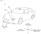
- FIG. 1 is a diagram illustrating the external appearance of a vehicle according to an embodiment of the present invention.
- a vehicle 10 may include a plurality of wheels, which are rotated by a power source, and a steering input device for controlling a driving direction of the vehicle 10.
- the vehicle 10 may include a laser head lamp 100 for vehicle.
- the laser head lamp 100 includes a low beam lamp module and a high beam lamp module.
- the laser head lamp 100 may include a left-hand head lamp module 160a, and a right-hand head lamp module 160b.
- the left-hand head lamp module 160a may include a left-hand low beam lamp module, and a left-hand high beam lamp module.
- the right-hand head lamp module 160b may include a right-hand low beam lamp module, and a right-hand high beam lamp module.
- overall length means the length from the front end to the rear end of the vehicle 10
- overall width means the width of the vehicle 10
- overall height means the height from the bottom of the wheel to the roof.
- overall length direction L may mean the reference direction for the measurement of the overall length of the vehicle 10
- overall width direction W may mean the reference direction for the measurement of the overall width of the vehicle 10
- overall height direction H may mean the reference direction for the measurement of the overall height of the vehicle 10.
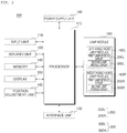
- FIG. 2 is a control block diagram of a laser head lamp for vehicle according to an embodiment of the present invention.
- FIG. 3 is a diagram illustrating a plurality of lamp modules according to an embodiment of the present invention.
- FIG. 4 is a diagram illustrating a unit lamp module according to an embodiment of the present invention.
- the laser head lamp (hereinafter, referred to as a head lamp) 100 may include a plurality of lamp modules 160, a processor 170, and a power supply unit 190.
- the head lamp 100 may further include an input unit 110, a sensing unit 120, an interface unit 130, a memory 140, a display 150, and a position adjustment unit 165 individually or in combination.
- the input unit 110 may receive a user input for controlling the head lamp 100.
- the input unit 110 may include at least one input device.
- the input unit 110 may include at least one of a touch input device, a mechanical input device, a gesture input device, and a voice input device.
- the input unit 110 may receive a user input for controlling operation of at least one from among the plurality of lamp modules 160.
- the input unit 110 may receive a user input for turning on or off at least one of the plurality of lamp modules 160.
- the input unit 110 may receive a user input for classifying two or more of the plurality of lamp modules 160 as a group.
- the sensing unit 120 may include one or more sensors.
- the sensing unit 120 may include a temperature sensor and an illumination sensor.
- the sensing unit 120 may include a plurality of temperature sensors.
- the plurality of temperature sensors may acquire temperature information of the plurality of respective lamp modules 160.
- the interface unit 130 may exchange information, data, or a signal with another device provided in the vehicle 10.
- the interface unit 130 may transfer information, data, or a signal, received from another device provided in the vehicle 10, to the processor 170.
- the interface unit 130 may transmit information, data, or signal generated by the processor 170 to another device provided in the vehicle 10.
- the interface unit 130 may receive driving situation information.
- the driving situation information may include at least one of the following: information on an object outside of the vehicle 10 (which is hereinafter referred to as object information), navigation information, and vehicle state information.
- the object information may include the following: information on presence of an object; information on a location of the object; information on a distance between the vehicle 10 and the object; information on a speed relative to the object.
- the object information may be generated by an object detection apparatus provided in the vehicle 10.
- the object detection apparatus may detect an object based on sensing data which is generated by at least one of a camera, a radar, a lidar, an ultrasonic sensor, and an infrared sensor.
- An object may include a lane, a nearby vehicle, a pedestrian, a traffic signal, light, a road, a structure, a bump, a geographical feature, an animal, etc.
- the navigation information may include at least one selected from among map information, information on a set destination, information on a route to the set destination, information on various objects along the route, lane information, and information on a current location of the vehicle.
- the navigation information may be generated by a navigation apparatus provided in the vehicle 10.
- the vehicle state information may include vehicle position information, vehicle speed information, vehicle tilt information, vehicle weight information, vehicle direction information, vehicle battery information, vehicle fuel information, vehicle tire pressure information, vehicle steering information, in-vehicle temperature information, in-vehicle humidity information, pedal position information, vehicle engine temperature information, etc.
- the vehicle state information may be generated based on sensing information generated by various sensors provided in the vehicle 10.
- the memory 140 may store basic data for each unit of the head lamp 100, control data for the operational control of each unit, and data to be input to or output from the head lamp 100.
- the memory 140 may be any of various hardware storage devices, such as a ROM, a RAM, an EPROM, a flash drive, and a hard drive.
- the memory 140 may store various data for the overall operation of the head lamp 100, such as programs for the processing or control of the processor 170.
- the memory 149 may be classified as a subordinate element of the processor 170.
- the memory 140 may accumulate information on turn-on time of each of the plurality of lamp modules 160, and store the accumulated information.
- the display 150 may form a pattern or image based on an electrical signal from the processor 170.
- the display 150 may be a transparent display.
- the transparent display may include any one selected among a transparent TFEL, a transparent OLED, a transparent LCD, a transparent PDP, a transparent LED, and a transparent AMOLED.
- the display unit 150 may function as a shield of the head lamp 100. That is, the shield may be implemented as the display 150.
- the shield may be implemented as a transparent display that fully covers the plurality of lamp modules 160.
- the shield may block part of beams generated by some of the plurality of lamp modules 160.
- the shield may be implemented by a specific structural shape.
- the shield may be classified as a subordinate element of a beam pattern unit 420 which will be described later. That is, the beam pattern unit 420 may include the shield. Specifically, a patterning unit of the beam pattern unit 420 may include the shield.
- the plurality of lamp modules 160 may generate light and output the generated light.
- the plurality of lamp modules 160 may include an element which converts electrical energy into light energy.
- the plurality of lamp modules 160 may include a plurality of unit lamp modules.
- Each of the plurality of lamp modules 160 includes a Laser Diode (LD).
- LD Laser Diode
- the plurality of lamp modules 160 is configured to output at least one of a low beam and a high beam.
- the plurality of lamp modules 160 may include a left-hand head lamp module 160L and a right-hand head lamp module 160R.
- the plurality of lamp modules 160 comprises a first lamp module group 200 and a second lamp module group 300.
- the left-hand head lamp module 160L may include a first lamp module group 200L and a second lamp module group 300L.
- the right-hand head lamp module 160R may include a first lamp module group 200L and a second lamp module group 300R.
- first and second lamp module groups 200 and 300 may be applied to the first and second lamp module groups 200L and 300L in the left-hand head lamp module 160L and the first and second lamp module groups 200R and 300R in the right-hand head lamp module 160R.
- the first lamp module group 200 generates a low beam by a default option.
- the first lamp module group 200 may include a plurality of lamp modules 210, 220, 230, and 240.
- FIG. 3 illustrates an example in which four lamp modules 210, 220, 230, and 240 are provided, but the number of lamp modules may be two, three, five, or more.
- Each of the plurality of lamp modules 210, 220, 230, and 240 ma include a first light emitting unit and a first beam pattern unit.
- the first light emitting unit may include a laser diode as a light source.
- the first light emitting unit may be used together with a second light emitting unit.
- the first light emitting unit may have the same structure and the same components as a second light emitting unit of each of the lamp modules 310, 320, 330, and 340 included in the second lamp module group 300.
- the first beam pattern unit may generate a low beam pattern based on light generated from the laser diode of the first light emitting unit.
- the second lamp module group 300 generates a high beam by a default option.
- the second lamp module group 300 may include a plurality of lamp modules 310, 320, 330, and 340.
- FIG. 3 illustrates an example in which four lamp modules 310, 320, 330, and 340 are provided, but the number of lamp modules may be two, three, five, or more.
- Each of the plurality of lamp modules 310, 320, 330, and 340 may include a second light emitting unit and a second beam pattern unit.
- the second light emitting unit may include a laser diode as a light source.
- the second light emitting unit may be used together with the first light emitting unit.
- the second light emitting unit may have the same structure and the same components as the first light emitting unit of each of the lamp modules 210, 220, 230, and 240 included in the first lamp module group 200.
- the second beam pattern unit may generate a high beam pattern based on light generated by a laser diode of the second light emitting unit.
- Each of the lamp modules 210, 220, 230, 240, 310, 320, 330, and 340 may include a light emitting unit 410 and a beam pattern unit 420.
- the same description about the light emitting unit 410 in FIG. 4 may be applied to the aforementioned first and second light emitting units.
- the same description about the beam pattern unit 420 in FIG. 4 may be applied to the aforementioned first and second beam pattern units.
- the light emitting unit 410 may include a light source.
- the light source indicates an element that converts electrical energy into light energy.
- a laser diode is desirable.
- the light emitting unit 410 may output light toward the beam pattern unit 420.
- the beam pattern unit 420 may be disposed in front of the light emitting unit 410.
- the beam pattern unit 420 may form a beam pattern based on light generated by the light emitting unit 410.
- the beam pattern may be a low beam pattern or a high beam pattern.
- the beam pattern unit 420 may include a patterning unit.
- the patterning unit may be a transparent display that forms a pattern under the control of the processor 170.
- the patterning unit may be an architecture that is able to move under the control of the processor 170.
- the beam pattern unit 420 may further include a driving force generator (e.g., a motor, an actuator, and a solenoid) for providing a driving force to the architecture.
- a driving force generator e.g., a motor, an actuator, and a solenoid
- the processor 420 may form a low beam pattern using light generated by the light emitting unit 410.
- the beam pattern unit 420 may switch to a state in which it is enabled to form a high beam pattern, by the control of the patterning unit by the processor 170.
- the beam pattern unit 420 may form a high beam pattern using light generated by the light emitting unit 410. In addition, when forming a high beam pattern, the beam pattern unit 420 may switch to a state in which it is enabled to form a low beam pattern, by the control of the patterning unit by the processor 170.
- the position adjustment unit 165 may adjust positions of the plurality of lamp modules 160.
- the position adjustment unit 165 may control the plurality of lamp modules 160 to be tilted individually or together. Due to the tilting control for the plurality of lamp modules 160, output light may be adjusted in a vertical direction (e.g., an over-height direction).
- the position adjustment unit 165 may control the plurality of lamp modules 160 to be panned individually or together. Due to the panning control for the lamp module 160, output light may be adjusted in a horizontal direction (e.g., an over-length direction).
- the position adjustment unit 165 may further include a driving power generation unit (e.g., a motor, an actuator, and a solenoid) which provides driving power necessary to adjust the positions of the plurality of lamp modules 160.
- a driving power generation unit e.g., a motor, an actuator, and a solenoid
- the position adjustment unit 165 may adjust the position of a first lamp module group 200 and the position of a second lamp module group 300 all together.
- the position adjustment unit 165 may adjust the position of the first lamp module group 200 and the position of the second lamp module group 200 individually.
- the position adjustment unit 165 may include driving force generators, the number of which corresponds to the total number of the first lamp module group 200 and the second lamp module group 300.
- the position adjustment unit 165 may adjust lamp modules 210, 220, 230, 240 ,310, 320, 330, and 340 included in the plurality of lamp modules 160 individually.
- the position adjustment unit 165 may include driving force generators, the number of which corresponds to the total number of lamp modules 210, 220, 230, 240, 310, 320, 330, and 340.
- the position adjustment unit 165 may adjust position of a corresponding lamp module to output light downward more than when the corresponding lamp module generates a high beam.
- the position adjustment unit 165 may adjust position of a corresponding lamp module to output light downward more than when the corresponding lamp module outputs a low beam.
- the processor 170 may be electrically connected to each component of the head lamp 100.
- the processor 170 may control overall operation of each component of the head lamp 100.
- the processor 170 may control at least one of the display 150, the plurality of lamp modules 160, and the position adjustment unit 165 based on at least one of the following: information on turn-on time of the plurality of lamp modules 160, a user input, temperature information, and driving situation information.
- the processor 170 acquires turn-on time of each of the plurality of lamp modules 160.
- the processor 170 may accumulate information on turn-on time of each of the plurality of lamp modules 160, and store the accumulated information in the memory 140.
- the processor 170 may retrieve the accumulated information from the memory 140.
- the processor 170 controls the plurality of lamp modules 160 based on turn-on time information of each of the plurality of lamp modules 160, so that the plurality of lamp modules 160 is turned on respectively.
- the plurality of lamp modules 160 may include a first lamp module including a first laser diode, and a second lamp module including a second laser diode.
- the processor 170 may acquire first information which is about a sum of the turn-on time of the first lamp module.
- the second processor 170 may acquire second information which is about a sum of the turn-on time of the second lamp module. Based on the first information and the second information, the processor 170 may control the first lamp module and the second lamp module to be turned on in a balanced manner.
- the processor 170 may turn on the second lamp module to output a low beam pattern. Then, the processor 170 may turn off the first lamp module.
- the reference value varies depending on an accumulated driving distance of the vehicle 10.
- the processor 170 may acquire temperature information of each of the plurality of lamp modules 160 from the sensing unit 120.
- the processor 170 may control the plurality of lamp modules 160 to be turned on in a balanced manner.
- the plurality of lamp modules 160 may include a first lamp module including a first laser diode, and a second lamp module including a second laser diode.
- the processor 170 may acquire temperature information of the first lamp module functioning as a low beam lamp. If a value indicative of temperature of the first lamp module is equal to or greater than a reference value, the processor 170 may turn off the second lamp module rather than the first lamp module. In this case the second lamp module may function as a low beam lamp.
- the processor 170 may turn on the second lamp module to output a low beam pattern. Then, the processor 170 may turn off the first lamp module.
- the first lamp module group 200 generates a low beam and a second lamp module group 300 generates a high beam.
- a first lamp module group 200 generates a low beam and a second lamp module group 300 generates a high beam.
- the processor 170 determines that a turn-on time of the first lamp module group 200 is greater than that of the second lamp module group 300, and that a difference between the turn-on time of the first lamp module group 200 and the turn-on time of the second lamp module group 300 exceeds a reference range. In this case, the processor 170 is configured to turn off the first lamp module group 200 and turn on the second lamp module group 300 to generate a low beam.
- the turn-on time of the first lamp module group 200 may be the total sum or average of the turn-on time of the lamp modules 210, 220, 230, and 240 included in the first lamp module group 200.
- the turn on time of the second lamp module group 200 may be the total sum or average of the turn-on time of the lamp modules 310, 320, 330, and 340 included in the second lamp module group 300.
- the processor 170 may control the plurality of lamp modules 160, so that only some lamp modules in the first lamp module group 200 are turned on to generate a low beam.
- the processor 170 may determine a combination of lamp modules to be turned on so as to generate a low beam.
- the first lamp module group 200 may include first to fourth lamp modules 210, 220, 230, and 240.
- the processor 170 may turn on the first, second, and third lamp modules 210, 220, and 230 to generate a low beam.
- the processor 240 may determine that a turn-on time of the third lamp module 230 becomes greater than a turn-on time of the fourth lamp module 240. In this case, the processor 170 may turn on the fourth lamp module 240 and then turn off the third lamp module 230, so that the first, second, and fourth lamp modules 210, 220, and 240 generate a low beam.
- the processor 170 may turn on some lamp modules in the first lamp module group 200 and some of the second lamp module group 300 to generate a low beam.
- the processor 170 may determine a combination of lamp modules to be turned on so as to generate a low beam.
- the processor 170 may select more lamp modules from the second lamp module group 300 than from the first lamp module group 200 to determine a combination of lamp modules which will be turned on to generate a low beam.
- the processor 170 may generate a low beam with a combination of one lamp module from the first lamp module group 200 and three lamp modules from the second lamp module group 300.
- the processor 170 may acquire temperature information of the first lamp module group 200.
- the processor 170 may determine that temperature of the first lamp module group 200 outputting light with a second level of light quantity is equal to or greater than a reference value. If it is determined that the temperature of the first lamp module group 200 is equal to or greater than the reference value, the processor 170 may reduce the light quantity of the first lamp module group 200 to a first level.
- the first level indicates a light quantity smaller than the second level.
- the processor 170 may turn on the second lamp module group 300. In this case, it is preferable that the processor 170 may control light quantity of the second lamp module group 300 to be maintained as the same as light quantity of the first level.
- the processor 170 may perform a control operation to generats a low beam with all of the lamp modules in the first lamp module group 200 and the second lamp module group 300,.
- the processor 170 may acquire inoperable state information of the first lamp module 210 in the first lamp module group 200.
- the inoperable state information may include error state information or light source end-of-life information.
- the processor 170 may turn on any one lamp module from the first lamp group 200 and the second lamp module group 200, except for the first lamp module 210, to generate a low beam.
- the turned-on lamp module may replace the first lamp module.
- the processor 170 may receive information on an object outside of the vehicle 10 through the interface unit 130.
- the processor 170 may determine a lamp module among the plurality of lamp modules 160 to output light corresponding to the information on the object.
- the processor 170 may determine a combination of lamp modules selected from lamp modules other than the above-determined lamp module in the plurality of lamp modules 160, so that the combination of lamp modules are turned on so as to generate a low beam.
- the processor 170 may be implemented as at least one of application specific integrated circuits (ASICs), digital signal processors (DSPs), digital signal processing devices (DSPDs), programmable logic devices (PLDs), field programmable gate arrays (FPGAs), processors, controllers, micro-controllers, microprocessors, and electrical units for other functions.
- ASICs application specific integrated circuits
- DSPs digital signal processors
- DSPDs digital signal processing devices
- PLDs programmable logic devices
- FPGAs field programmable gate arrays
- processors controllers, micro-controllers, microprocessors, and electrical units for other functions.
- the power supply unit 190 may provide electrical energy required for operation of each unit of the head lamp 100.
- the power supply unit 190 may be supplied with power from a battery inside of the vehicle 10.
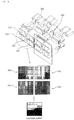
- FIG. 5 is a diagram for explanation of a shield of a head lamp according to an embodiment of the present invention.
- the head lamp 100 may further include a shield.
- the shield may block part of beams generated by some of the plurality of lamp modules 160.
- the shield may be implemented as a display 150.
- the shield may be implemented as a transparent display.
- the display 150 may include a first display 510 and a second display 520.
- the display 150 may form a pattern or image. Using the pattern or image formed in the display 150, a beam pattern may be formed.
- the display 510 may be classified as a subordinate element of the beam pattern unit 420. Specifically, the display 510 may be classified as a subordinate element of the patterning unit of the beam pattern unit 420.
- the first display 510 may be disposed in front of the first lamp module group 200.
- the first display 510 may form a first pattern based on the control of the processor 170.
- the first display 510 may form the first pattern including a shield portion 511 and a translucent portion 512.
- Part of light generated by a first light emitting unit may be blocked by the shield portion 511.
- the rest of light generated by the first light emitting unit may be transmitted through the translucent portion 512.
- a low beam pattern may be formed in an area in front of the vehicle 10.
- the first display 510 may be classified as a subordinate element of the first beam pattern unit.
- the second display 520 may be disposed in front of the second lamp module group 300.
- the second display 520 may form a second pattern based on the control of the processor 170.
- the second display 520 may form a second pattern including a translucent portion 522.
- Light generated by the second light emitting unit may be transmitted through the translucent portion 522.
- a low beam pattern may be formed in an area in front of the vehicle 10.
- the second display 520 may be classified as a subordinate element of the second bema pattern unit.
- the same description about the first display 510 may be applied to the second display 520.
- FIG. 6 is a diagram for explanation of a shield of a head lamp according to an embodiment of the present invention.
- a shield may include a plurality of sub-shields.
- the plurality of sub-shields may be disposed to correspond to a plurality of lamp modules 160, respectively.
- the plurality of lamp modules 160 may include a first lamp module and a second lamp module.
- the shield may include a first sub-shield and a second sub-shield.
- the first sub-shield may be disposed in front of a first lamp module.
- the first sub-shield may include a first pattern.
- the first sub-shield may be a display.
- the first sub-shield may be an architecture.
- the second sub-shield may be disposed in front of the second lamp module.
- the second sub shield may include a second pattern.
- the second pattern may be different from the first pattern.
- the second sub-shield may be a display.
- the second sub-shield may be an architecture.
- the processor 170 may turn on a combination of lamp modules in the first and second lamp module groups among the plurality of lamp modules 160 to generate a low beam.
- the display 500 may include a plurality of sub-displays.
- the number of sub-displays may correspond to the number of lamp modules included in the plurality of lamp modules 160.
- the first display 510 may include a plurality of sub-displays.
- the number of sub-displays may correspond to the number of lamp modules included in the first lamp module group 200.
- the first display 510 may include first to fourth sub-displays 510a, 510b, 510c, and 510d.
- the first sub-display 510a may be disposed in front of the first lamp module 210 included in the first lamp module group 200.
- the first sub-display 510a may form a first pattern based on the control of the processor 170.
- the first sub-display 510a may function as a first sub-shield.
- the second sub-display 510b may be disposed in front of the second lamp module 220 included in the first lamp module group 200.
- the second sub-display 510b may form a second pattern based on the control of the processor 170.
- the second sub-display 510b may function as a second sub-shield.
- the third sub-display 510c may be disposed in front of the third lamp module 230 included in the first lamp module group 200.
- the third sub-display 510c may form a third pattern based on the control of the processor 170.
- the third sub-display 510c may function as a third sub-shield.
- the fourth sub-display 510d may be disposed in front of the fourth lamp module 240 included in the first lamp module group 200.
- the fourth sub-display 510d may form a fourth pattern based on the control of the processor 170.
- the fourth sub-display 510d may function as a fourth sub-shield.
- the first to fourth patterns may have different shapes. Combined with each other, the first to fourth patterns may form a low beam pattern.
- the second display 520 may include a plurality of sub-displays.
- the number of sub-displays may correspond to the number of lamp modules included in the second lamp module group 300.
- the same description about the sub-displays included in the first display 510 may be applied to the plurality of sub-displays included in the second display 520.
- FIGS. 7A to 14 are diagrams illustrating various operations of a head lamp according to an embodiment of the present invention.
- FIGS. 7A and 7B are diagrams illustrating an operation of controlling a plurality of lamp modules on the basis of a group unit according to the present invention.
- the first lamp module group 200 functions as a low beam lamp by a default option.
- the first lamp module group 200 forms a low beam pattern.
- the second lamp module group 300 functions as a high beam lamp by a default option.
- the second lamp module group 300 forms a high beam pattern.
- the processor 170 acquires turn-on time information of each of the first and second lamp module groups 200 and 300.
- the processor 170 determines whether a turn-on time of the first lamp module group 200 is greater than a turn-on time of the second lamp module group 300.
- the processor 170 determines whether a difference between the turn-on time of the first and second lamp module groups 200 and the turn-on time of the second lamp module group 300 exceeds a reference range.
- the processor 170 is configured to turn off the first lamp module group 200 and turn on the second lamp module group 300 to generate a low beam. At this point, the processor 170 may first turn on the second lamp module group 300 and then turn off the first lamp module group 200.
- the second lamp module group 300 may function as a low beam lamp.
- the second lamp module group 300 may form a low beam pattern.
- FIG. 8 is a diagram illustrating an operation of controlling a first lamp module group according to an embodiment of the present invention.
- a low beam lamp may be implemented as a combination of some lamp modules in the first lamp module group 200.
- the processor 170 may turn on just some lamp modules in the first lamp module group 200 to generate a low beam.
- the processor 170 may determine a combination of lamp modules to be turned on so as to generate a low beam.
- the first lamp module group 200 may include the first to fourth lamp modules 210, 220, 230, and 240.
- the processor 170 may determine a combination of three lamp modules from the four lamp modules. In this case, the combination of three lamp modules may generate a low beam.
- the processor 170 may determine the second, third, and fourth lamp modules 220, 230, and 240, except for the first lamp module 210, to constitute a combination of lamp modules for generating a low beam.
- the processor 170 may determine the first, third, and fourth lamp modules, 210, 230, and 240, except for the second lamp module 220, to constitute a combination of lamp modules for generating a low beam.
- the processor 170 may determine the first, second, and fourth lamp modules, 210, 220, and 240, except for the third lamp module 230, to constitute a combination of lamp modules for generating a low beam.
- the processor 170 may determine the first, second, and third lamp modules, 210, 220, and 230, except for the fourth lamp module 240, to constitute a combination of lamp modules for generating a low beam.
- the processor 170 may determine to modify a combination of the lamp modules operating as a low beam lamp, based on turn-on time information of each lamp module in the first lamp module group 200.
- the processor 170 may control the first, second, and third lamp modules 210, 220, and 230 to operate as a low beam lamp. If it is determined, during the operation, that the first lamp module 210 has the greatest turn-on time in the first lamp module group 200, the processor 170 may turn on the fourth lamp module 240 and then turn off the first lamp module 210. In this case, the second, third, and fourth lamp modules 220, 230, and 240 operate as a low beam lamp.
- FIGS. 9 to 11 are diagram illustrating an operation of controlling first and second lamp module groups according to an embodiment of the present invention.
- the processor 170 may turn on some lamp modules in the first lamp module group 200 and some lamp modules in the second lamp module group 300 so as to generate a low beam.
- the processor 170 may determine a combination of lamp modules to be turned on so as to generate a low beam.
- the first lamp module group 200 may function as a low beam lamp by a default option.
- the first lamp module group 200 may form a low beam pattern.
- the second lamp module group 300 may function as a high beam lamp by a default option.
- the second lamp module group 300 may form a high beam pattern.
- the processor 170 may determine that the turn-on time of some lamp modules (e.g., the first and second lamp modules 210 and 220) in the first lamp module group 200 is greater than a reference value. In this case, the processor 170 may exclude a lamp module, whose turn-on time is equal to or greater than the reference value, from a combination of lamp modules to be turned on so as to generating a low beam.
- some lamp modules e.g., the first and second lamp modules 210 and 220
- the processor 170 may exclude a lamp module, whose turn-on time is equal to or greater than the reference value, from a combination of lamp modules to be turned on so as to generating a low beam.
- the processor 170 may determine a combination of lamp modules to be turned on so as to generate a low beam, by selecting some lamp modules (e.g., the first and second lamp modules 310 and 320) in the second lamp module group 300 in addition to lamp modules (e.g., the third and fourth lamp modules 230 and 240) having a turn-on time smaller than the reference value in the first lamp module group 200.
- some lamp modules e.g., the first and second lamp modules 310 and 320
- lamp modules e.g., the third and fourth lamp modules 230 and 240
- the reference value is a value that changes depending upon an accumulated driving distance of the vehicle 10.
- the processor 170 may select more lamp modules from the second lamp module group 300 than from the first lamp module group 200 to determine a combination of lamp modules which will be turned on to generate a low beam.
- the processor 170 may determine that the turn on time of three lamp modules (e.g., the first, second, and third lamp modules 210, 220, and 230) in the first lamp module group 200 is greater than a reference value. In this case, the processor 170 may exclude the lamp modules, whose turn-on time is equal to or greater than the reference value, from a combination of lamp modules to be turned on so as to generate a low beam.
- three lamp modules e.g., the first, second, and third lamp modules 210, 220, and 230
- the processor 170 may determine a combination of lamp modules to be turned on so as to generate a low beam, by selecting some lamp modules (e.g., the first, third, and fourth lamp module 310, 330, and 340) in the second lamp module group 300 in addition to a lamp module (e.g., the third lamp module 230) having a turn on time smaller than the reference value in the first lamp module group 200.
- some lamp modules e.g., the first, third, and fourth lamp module 310, 330, and 340
- a lamp module e.g., the third lamp module 230
- the processor 170 may determine that the turn-on time of one lamp module in the first lamp module group 200 is equal to or greater than a reference value. In this case, the processor 170 may exclude a lamp module, whose turn-on time is equal to or greater than the reference value, from a combination of lamp modules to be turned on so as to generate a low beam.
- the processor 170 may determine a combination of lamp modules to be turned on so as to generate a low beam, by selecting some lamp modules (e.g., the second lamp module 320) in the second lamp module group 300 in addition to lamp modules (e.g., the first, second, and fourth lamp modules 210, 220, and 240) having a turn-on time smaller than the reference value in the first lamp module group 200.
- some lamp modules e.g., the second lamp module 320
- lamp modules e.g., the first, second, and fourth lamp modules 210, 220, and 240
- the processor 170 may determine a lamp modules in the first lamp module group 200 to be excluded from a combination of lamp modules which is to be turned on so as to generate a low beam.
- the processor 170 may determine that the turn-on time of the first lamp module 210 in the first lamp module group 200 is equal to or greater than a reference value. In this case, the processor 170 may determine the first lamp module 210 to be a lamp module will be excluded from a combination of lamp modules which is to be turned on so as to generate a low beam.
- the processor 170 may determine a lamp module in the second lamp module group 300 to be turned on so as to generate a low beam.
- the processor 170 may determine lamp modules to be turned on for generating a low beam from among the second lamp module group 300 in a sequence whereby a lamp module having the smallest turn-on time is determined first.
- the processor 170 may determine that the second lamp module 320 has the smallest turn-on time in the second lamp module group 300. In this case, the processor 170 may determine the second lamp module 320 to be a lamp module which will be added to a combination of lamp modules to be turned on so as to generate a low beam.
- the processor 170 may control the first module lamp group 200 to output a low beam pattern by a default option. In this case, the processor 170 may control the first lamp module group 200 to output light with a second level quantity.
- the processor 170 may acquire temperature information of the first lamp module group 200.
- the processor 170 may determine whether temperature of the first lamp module group 200 which is now outputting light with quantity of a second level is equal to or greater than a reference value.
- the processor 170 may reduce the quantity of light from to be output from the first lamp module group 200.
- a quantity value of the first level may be smaller than a quantity value of the second level.
- the processor 170 may reduce the quantity of light to be output from the first lamp module group 200.
- the processor 170 may turn on the second lamp module group 300. In this case, the processor 170 may control the second lamp module 300 to maintain a quantity of light at the first level.
- the processor 170 may perform a control operation to generate a low beam using the first lamp module group 200 and the second lamp module group 300.
- the processor 170 may control an illumination area of the second lamp module group 300 to match with an illumination area of the first lamp module group 200.
- the processor 170 may control the beam pattern unit 420 (see FIG. 4 ) to match the illumination area of the second lamp module group 300 with the illumination area of the first lamp module group 200.
- FIG. 12 is a diagram illustrating an operation of controlling a plurality of lamp modules when any one among the plurality of lamp modules is in an inoperable state, according to an embodiment of the present invention.
- one lamp module in the first lamp module group 200 functioning as a low beam lamp may be in an inoperable state.
- the first lamp module 210 in the first lamp module 200 may be in an inoperable state.
- the inoperable state may indicate an error state or a light source end-of-life state.
- the processor 170 may acquire inoperable state information of a lamp module.
- the processor 170 may receive inoperable state information of the first lamp module 210 in the first lamp module group 200.
- the processor 170 may turn on lamp modules other than the first lamp module 210 in the first lamp module group 200 and any one lamp module in the second lamp module group 300 so as to generate a low beam.
- the processor 170 may turn on the first lamp module 310 in the second lamp module group 300 functioning as a high beam lamp.
- the processor 170 may perform a control operation to generate a low beam with a combination of the first lamp module 310 in the second lamp module group 300 and the turned-on second, third, and fourth modules 220, 230, and 240 in the first lamp module group 200.
- the processor 170 may increase the quantity of light from the second, third, and fourth lamp modules 220, 230, and 240. That is, the processor 170 may compensate for the absence of the quantity of light output from the first lamp module 210 in the inoperable state by using the quantity of light output from the second, third, and fourth lamp modules 220, 230, and 240. The processor 170 may increase the quantity of output light by increasing the quantity of current to be applied to the second, third, and fourth lamp modules 220, 230, and 240.
- FIGS. 13 and 14 are diagram illustrating an operation of controlling a plurality of lamp modules when one of the plurality of lamp modules is used for a different function, according to an embodiment of the present invention.
- the processor 170 may receive, through the interface unit 130, information on an object 1310 outside of the vehicle 10.
- the information on the object 1310 may include: information on the presence of the object 1310; information on a location of the object 1310; information on a distance between the vehicle 10 and the object 1310; and information on a relative speed of the object 1310.
- the information on the object 1310 may be generated by an object detection apparatus provided in the vehicle 10.
- the object detection apparatus may detect the object 1310 based on sensing data generated by at least one of a camera, a radar, a lidar, an ultrasound sensor, and an infrared sensor.
- the object 1310 may include a lane, a nearby vehicle, a pedestrian, a two-wheeled vehicle, a traffic signal, light, a road, a structure, a bump, a geographical feature, an animal, etc.
- the lane may be a lane in which the vehicle 10 is traveling or a lane next to the lane in which the vehicle 10 is traveling.
- the lane may be a concept including left and right lines that define the lane.
- the lane may be a concept including an intersection.
- the nearby vehicle may be a vehicle that is travelling in the vicinity of the vehicle 10.
- the nearby vehicle may be a vehicle within a predetermined distance from the vehicle 10.
- the nearby vehicle may be a vehicle that is preceding or following the vehicle 10.
- the pedestrian may be a person in the vicinity of the vehicle 10.
- the pedestrian may be a person within a predetermined distance from the vehicle 10.
- the pedestrian may be a person on a sidewalk or on the roadway.
- the two-wheeled vehicle is a vehicle that is located in the vicinity of the vehicle 10 and moves with two wheels.
- the two-wheeled vehicle may be a vehicle that has two wheels within a predetermined distance from the vehicle 10.
- the two-wheeled vehicle may be a motorcycle or a bike on a sidewalk or the roadway.
- the traffic signal may include a traffic light, a traffic sign plate, and a pattern or text painted on a road surface.
- the light may be light generated by a lamp provided in the nearby vehicle.
- the light may be light generated by a street light.
- the light may be solar light.
- the road may include a road surface, a curve, and slopes, such as an upward slope and a downward slope.
- the structure may be a body located in the vicinity of the road in the state of being fixed onto the ground.
- the structure may include a streetlight, a roadside tree, a building, a traffic light, and a bridge.
- the geographical feature may include a mountain and a hill.
- the object 1310 may be classified as a movable object 1310 or a stationary object 1310.
- the movable object 1310 may include a nearby vehicle and a pedestrian.
- the stationary object 1310 may include a traffic signal, a road, and a structure.
- the processor 170 may output light corresponding to the information on the object 1310.
- the processor 170 may control outputting of light toward the crosswalk, the pedestrian, the two-wheeled vehicle, or the traffic light.
- the processor 170 may determine one of the plurality of lamp modules to output light corresponding to the information on the object 1310.
- the processor 170 may determine any one lamp module from the second lamp module group 300, functioning as a high beam lamp, to output light corresponding to the information on the object 1310.
- the processor 170 may determine a lamp module having the smallest turn-on time in the second lamp module group 300 to be a lamp module for outputting light corresponding to the information on the object 1310.
- the processor 170 may determine the first lamp module 310 to be a lamp module for outputting light corresponding to the information on the object 1310.
- the processor 170 may control the determined lamp module 310 to output light toward the object 1310.
- the processor 170 may adjust an illumination range based on information on relative movement of the object 1310.
- the processor 170 may adjust an illumination range based on information on a distance relative to the object 1310.
- the processor 170 may adjust the quantity of light to be output from the first lamp module 310, based on the information on a distance relative to the object 1310.
- the processor 170 may adjust the quantity of light to be output from the first lamp module 310, based on information on a type of the object 1310.
- the processor 170 may control the quantity of light such that the shorter the distance to a pedestrian or two-wheeled vehicle, the greater the quantity of light from the first lamp module 310 is reduced.
- the processor 170 may control the quantity of light such that the shorter the distance to a crosswalk or traffic light, the greater the quantity of light from the first lamp module 310 is increased.
- the processor 170 may adjust an illumination range based on the information on a relative speed of the object 1310.
- the processor 170 may adjust the quantity of light to be output from the first lamp module 310, based on the information on a relative speed of the object 1310.
- the processor 170 may control the quantity of light such that the higher the relative speed of the object 1310, the greater the quantity of light from the first lamp module 310 is increased.
- the processor 170 may change a lamp module for outputting light corresponding to the information on the object 1310.
- the processor 170 may control any one of the plurality of lamp modules 160 to operate as a Daytime Running lamp (DRL).
- DRL Daytime Running lamp
- the processor 170 may determine a lamp module to operate as the DRL.
- the processor 170 may control the second lamp module 220 in the first lamp module group 200 to operate as a DRL.
- the processor 170 may determine whether to change a lamp module which is operating as a DRL.
- the processor 170 may control the fourth lamp module 240 to operate as a DRL.
- FIGS. 15 and 16 are diagrams illustrating various operations of a head lamp according to an embodiment of the present invention.
- the head lamp 100 includes a plurality of left-hand lamp modules 160L and a plurality of right-hand lamp modules 160R.
- Each of the plurality of left-hand lamp modules 160L may include a laser diode.
- the plurality of left-hand lamp modules 160L may operate as at least one of a left-hand low beam lamp and a left-hand high beam lamp.
- Each of the plurality of right-hand lamp module 160R may include a laser diode.
- the plurality of right lamp module 160R may operate as at least one of a right-hand low beam lamp and a right-hand high beam lamp.
- the processor 170 may control the plurality of left-hand lamp modules and the plurality of right-hand lamp modules.
- the processor 170 may acquire turn-on time information of each of the plurality of left-hand lamp modules 160L and the plurality of right-hand lamp modules 160R.
- the processor 170 may control the plurality of left-hand lamp modules 160L and the plurality of right-hand lamp modules 160R, so that the plurality of left-hand lamp modules 160L and the plurality of right-hand lamp modules 160R are respectively turned on in a balanced manner.
- the processor 170 may perform a control operation such that some of the plurality of left-hand lamp modules 160L and some of the plurality of right-hand lamp modules 160R generate a left-hand low beam.
- the processor 170 may turn on some of the plurality of left-hand lamp modules 160L and some of the plurality of right-hand lamp modules 160R so as to generate a left-hand low beam.
- the processor 170 may perform a control operation such that one of the plurality of right-hand lamp modules 160R generates a left-hand low beam.
- the processor 170 may perform a control operation such that any one lamp module in a second lamp module group 300L operating as a right-hand high beam lamp among the plurality of right-hand lamp modules 160L generates a left-hand low beam.
- the processor 170 may perform a control operation such that some of the plurality of left-hand lamp modules 160L and some of the plurality of right-hand lamp modules 160R generate a right-hand low beam.
- the processor 170 may turn on some of the plurality of left-hand lamp modules 160L and some of the plurality of right-hand lamp modules 160R so as to generate a right-hand low beam.
- the processor 170 may perform a control operation such that one of the plurality of left-hand lamp modules 160L generates a right-hand low beam.
- the processor 170 may perform a control operation such that any one lamp module in a second lamp module group 300L operating as a left-hand high beam lamp among the plurality of left-hand lamp modules 160L generates a right-hand low beam.
- the processor 170 may output light corresponding to information on an object 1310.
- the processor 170 may determine a lamp module to output light corresponding to object information.
- the processor 170 may change a lamp module which outputs light corresponding to object information.
- the processor 170 may determine a first lamp module 310L out of the plurality of left-hand head lamp module 160L to be a lamp module which outputs light corresponding to object information.
- the processor 170 may switch a first lamp module 310R out of the plurality of right-hand head lamp module 160R to be a lamp module for outputting light corresponding to object information.
- the present invention as described above may be implemented as code that can be written on a computer-readable medium in which a program is recorded and thus read by a computer.
- the computer-readable medium includes all kinds of recording devices in which data is stored in a computer-readable manner. Examples of the computer-readable recording medium may include a hard disk drive (HDD), a solid state disk (SSD), a silicon disk drive (SDD), a read only memory (ROM), a random access memory (RAM), a compact disk read only memory (CD-ROM), a magnetic tape, a floppy disc, and an optical data storage device.
- the computer-readable medium may be implemented as a carrier wave (e.g., data transmission over the Internet).
- the computer may include a processor or a controller.
Landscapes
- Engineering & Computer Science (AREA)
- General Engineering & Computer Science (AREA)
- Mechanical Engineering (AREA)
- Physics & Mathematics (AREA)
- Optics & Photonics (AREA)
- Chemical & Material Sciences (AREA)
- Crystallography & Structural Chemistry (AREA)
- Lighting Device Outwards From Vehicle And Optical Signal (AREA)
Claims (13)
- Ein Laserscheinwerfer (100) für ein Fahrzeug, umfassend:eine Vielzahl von Lampenmodulen (160), die jeweils eine Laserdiode aufweisen und eingerichtet sind, ein Abblendlicht und/oder ein Fernlicht auszugeben; undeinen Prozessor (170), welcher eingerichtet ist, Einschaltzeitinformationen von jedem der mehreren Lampenmodule (160) zu erfassen und die mehreren Lampenmodule (160) auf der Grundlage der erfassten Informationen derart anzusteuern, dass die mehreren Lampenmodule (160) jeweils eingeschaltet werden,wobei die Mehrzahl von Lampenmodulen (160) umfasst:eine erste Lampenmodulgruppe (200), welche eingerichtet ist, das Abblendlicht zu erzeugen; undeine zweite Lampenmodulgruppe (300), welche zur Erzeugung des Fernlichts eingerichtet ist, und wobei, wenn der Prozessor (170) feststellt, dass eine Einschaltzeit der ersten Lampenmodulgruppe (200) größer als eine Einschaltzeit der zweiten Lampenmodulgruppe (300) ist, und dass eine Differenz zwischen der Einschaltzeit der ersten Lampenmodulgruppe und der Einschaltzeit der zweiten Lampenmodulgruppe einen Referenzbereich überschreitet, der Prozessor (170) ferner eingerichtet ist, dass er die erste Lampenmodulgruppe (200) ausschaltet und die zweite Lampenmodulgruppe (300) einschaltet, um ein Abblendlicht zu erzeugen.
- Laserscheinwerfer (100) nach Anspruch 1, wobei der Prozessor (170) ferner eingerichtet ist:Temperaturinformationen von jedem der Vielzahl von Lampenmodulen (160) zu erfassen; unddie Mehrzahl von Lampenmodulen (160) ferner auf der Grundlage der Temperaturinformation so zu steuern, dass die Mehrzahl von Lampenmodulen jeweils eingeschaltet wird.
- Laserscheinwerfer (100) nach Anspruch 1 oder 2, ferner umfassend: eine Abschirmung, die eingerichtet ist, dass sie einen Teil der Strahlen blockiert, die von mindestens einem der mehreren Lampenmodule (160) erzeugt werden.
- Laserscheinwerfer (100) nach Anspruch 3, wobei die Abschirmung weiterhin eingerichtet ist, dass sie als eine transparente Anzeige (150) implementierbar ist, welche die Vielzahl von Lampenmodulen (160) vollständig abdeckt.
- Laserscheinwerfer (100) nach Anspruch 3, wobei die Mehrzahl von Lampenmodulen (160) umfasst:ein erstes Lampenmodul; undein zweites Lampenmodul,wobei die Abschirmung umfasst:eine erste Teilabschirmung, die vor dem ersten Lampenmodul angeordnet ist und eine erste Lichtverteilung aufweist; undeine zweite Teilabschirmung, die vor dem zweiten Lampenmodul angeordnet ist und eine zweite Lichtverteilung aufweist, das sich von der ersten Lichtverteilung unterscheidet, undwobei der Prozessor (170) ferner eingerichtet ist, dass er eine Kombination von Lampenmodulen (160), die das erste Lampenmodul und das zweite Lampenmodul aus der Vielzahl von Lampenmodulen (160) umfasst, einschaltet, um ein Abblendlicht zu erzeugen.
- Laserscheinwerfer (100) nach einem der Ansprüche 1 bis 5, wobei jedes aus einer Vielzahl von Lampenmodulen (210, 220, 230, 240), die in der ersten Lampenmodulgruppe (200) enthalten sind, umfasst:eine erste lichtemittierende Einheit mit der Laserdiode; undeine erste Lichtverteilungseinheit, die eingerichtet ist, dass sie eine Abblendlichtverteilung auf der Grundlage des von der Laserdiode der ersten lichtemittierenden Einheit erzeugten Lichts erzeugt,wobei jedes einer Vielzahl von Lampenmodulen (310, 320, 330, 340), die in der zweiten Lampenmodulgruppe (300) enthalten sind, umfasst:eine zweite lichtemittierende Einheit mit der Laserdiode; undeine zweite Lichtverteilungseinheit, die eingerichtet ist, dass sie eine Fernlichtverteilung auf der Grundlage des von der Laserdiode der zweiten lichtemittierenden Einheit erzeugten Lichts erzeugt, undwobei eine Struktur und Komponenten der ersten lichtemittierenden Einheit identisch mit einer Struktur und Komponenten der zweiten lichtemittierenden Einheit sind.
- Laserscheinwerfer (100) nach einem der Ansprüche 1 bis 6, wobei der Prozessor (170) ferner eingerichtet ist, dass er nur einige Lampenmodule (210, 220, 230, 240) in der ersten Lampenmodulgruppe (200) einschaltet, um ein Abblendlicht zu erzeugen.
- Laserscheinwerfer (100) nach Anspruch 7, wobei der Prozessor (170) ferner eingerichtet ist ist, dass er eine Einschaltzeit jedes Lampenmoduls (210, 220, 230, 240) in der ersten Lampenmodulgruppe (200) bestimmt und auf der Grundlage dieser Bestimmung eine Kombination von Lampenmodulen (210, 220, 230, 240) der ersten Lampenmodulgruppe (200) bestimmt, die einzuschalten sind, um ein Abblendlicht zu erzeugen.
- Laserscheinwerfer (100) nach einem der Ansprüche 1 bis 6, wobei der Prozessor (170) ferner eingerichtet ist, dass er einige Lampenmodule (210, 220, 230, 240) in der ersten Lampenmodulgruppe (200) und einige Lampenmodule (310, 320, 330, 340) in der zweiten Lampenmodulgruppe (300) einschaltet, um so ein Abblendlicht zu erzeugen.
- Laserscheinwerfer (100) nach Anspruch 9, wobei der Prozessor (170) ferner eingerichtet ist, dass er eine Einschaltzeit jedes Lampenmoduls (210, 220, 230, 240; 310, 320, 330, 340) in der ersten und zweiten Lampenmodulgruppe (200, 300) bestimmt und auf der Grundlage dieser Bestimmung eine Kombination von Lampenmodulen (210, 220, 230, 240; 310, 320, 330, 340) der ersten und zweiten Lampenmodulgruppe (200, 300) bestimmt, die einzuschalten sind, um ein Abblendlicht zu erzeugen.
- Laserscheinwerfer (100) nach einem der Ansprüche 1 bis 10, wobei der Prozessor (170) ferner eingerichtet ist, dass er Temperaturinformationen der ersten Lampenmodulgruppe (200) erfasst, und wobei, wenn der Prozessor (170) bestimmt, dass die Temperatur der ersten Lampenmodulgruppe (200) gleich oder größer als ein Referenzwert ist, der Prozessor (170) ferner eingerichtet ist, um eine Lichtmenge von der ersten Lampenmodulgruppe (200) auf ein erstes Niveau zu reduzieren und die zweite Lampenmodulgruppe (300) einzuschalten, so dass ein Abblendlicht unter Verwendung der ersten Lampenmodulgruppe (200) und der zweiten Lampenmodulgruppe (300) erzeugt wird.
- Laserscheinwerfer (100) nach einem der Ansprüche 1 bis 11, wobei der Prozessor (170) ferner eingerichtet ist:Informationen über den nicht betriebsbereiten Zustand eines ersten Lampenmoduls (210, 220, 230, 240) in der ersten Lampenmodulgruppe (200) zu erfassen; undLampenmodule (210, 220, 230, 240) mit Ausnahme des ersten Lampenmoduls (210, 220, 230, 240) in der ersten Lampenmodulgruppe (200) und eines der Lampenmodule (310, 320, 330, 340) in der zweiten Lampenmodulgruppe (300) einzuschalten, um ein Abblendlicht zu erzeugen.
- Laserscheinwerfer (100) nach einem der Ansprüche 1 bis 12, weiter umfassend:
eine Schnittstelleneinheit (130), wobei der Prozessor (170) ferner eingerichtet ist:Informationen über ein Objekt außerhalb des Fahrzeugs über die Schnittstelleneinheit (130) zu empfangen; undbasierend auf der Einschaltzeitinformation von jedem der mehreren Lampenmodule (160), eines der mehreren Lampenmodule (160) zu bestimmen, um Licht entsprechend der Information über das Objekt außerhalb des Fahrzeugs auszugeben,und/oderwobei der Prozessor (170) ferner eingerichtet ist, dass er, basierend auf der Einschaltzeitinformation jedes der mehreren Lichtmodule (160), eine Kombination von Lampenmodulen bestimmt, die aus anderen Lampenmodulen als dem bestimmten Lampenmodul in den mehreren Lampenmodulen (160) ausgewählt sind, sodass die Kombination von Lampenmodulen eingeschaltet wird, um ein Abblendlicht zu erzeugen.
Applications Claiming Priority (1)
| Application Number | Priority Date | Filing Date | Title |
|---|---|---|---|
| KR1020170046793A KR102094679B1 (ko) | 2017-04-11 | 2017-04-11 | 차량용 레이저 헤드 램프 및 차량 |
Publications (2)
| Publication Number | Publication Date |
|---|---|
| EP3388739A1 EP3388739A1 (de) | 2018-10-17 |
| EP3388739B1 true EP3388739B1 (de) | 2020-12-09 |
Family
ID=61827521
Family Applications (1)
| Application Number | Title | Priority Date | Filing Date |
|---|---|---|---|
| EP18163989.9A Active EP3388739B1 (de) | 2017-04-11 | 2018-03-26 | Laserkopflampe für fahrzeug und fahrzeug |
Country Status (4)
| Country | Link |
|---|---|
| US (2) | US10189398B2 (de) |
| EP (1) | EP3388739B1 (de) |
| KR (1) | KR102094679B1 (de) |
| CN (1) | CN108692269B (de) |
Families Citing this family (10)
| Publication number | Priority date | Publication date | Assignee | Title |
|---|---|---|---|---|
| KR102094679B1 (ko) * | 2017-04-11 | 2020-04-01 | 제트카베 그룹 게엠베하 | 차량용 레이저 헤드 램프 및 차량 |
| US11521298B2 (en) | 2018-09-10 | 2022-12-06 | Lumileds Llc | Large LED array with reduced data management |
| JP7287979B2 (ja) * | 2018-09-25 | 2023-06-06 | 株式会社小糸製作所 | 灯具システムおよび車両用灯具 |
| KR102784317B1 (ko) | 2019-07-30 | 2025-03-24 | 삼성디스플레이 주식회사 | 표시장치 |
| KR102299339B1 (ko) * | 2019-11-04 | 2021-09-08 | 현대자동차주식회사 | 차량의 패턴 스킨 조명 장치 제어방법 |
| FR3114371A1 (fr) * | 2020-07-29 | 2022-03-25 | Valeo Vision | Dispositif lumineux d’éclairage et de signalisation |
| JP2022052142A (ja) * | 2020-09-23 | 2022-04-04 | スタンレー電気株式会社 | 車両用前照灯システム、車両用前照灯システムの制御方法 |
| CN116583434B (zh) * | 2020-12-15 | 2026-01-02 | 株式会社小糸制作所 | 车辆用前照灯 |
| KR102458716B1 (ko) * | 2021-03-23 | 2022-10-24 | 박정순 | 레이저 헤드램프 |
| CN116123475A (zh) * | 2021-11-12 | 2023-05-16 | 华域视觉科技(上海)有限公司 | 一种车灯模组、车灯及车辆 |
Family Cites Families (19)
| Publication number | Priority date | Publication date | Assignee | Title |
|---|---|---|---|---|
| FR2850616B1 (fr) * | 2003-01-30 | 2006-02-17 | Valeo Vision | Procede d'eclairage module d'une route et projecteur de vehicule mettant en oeuvre ce procede |
| JP4148910B2 (ja) | 2004-03-15 | 2008-09-10 | 株式会社小糸製作所 | 信号伝送システムおよび車両用灯具 |
| DE102005018175A1 (de) | 2005-04-19 | 2006-10-26 | Patent-Treuhand-Gesellschaft für elektrische Glühlampen mbH | LED-Modul und LED-Beleuchtungseinrichtung mit mehreren LED-Modulen |
| KR100798143B1 (ko) * | 2006-08-17 | 2008-01-28 | 에스엘 주식회사 | Led 램프 유닛을 적용한 적응형 전조등 장치 |
| JP4737066B2 (ja) * | 2006-12-19 | 2011-07-27 | パナソニック株式会社 | 照明装置とその制御方法 |
| JP5328861B2 (ja) * | 2010-09-21 | 2013-10-30 | シャープ株式会社 | 車両用前照灯および照明装置 |
| JP2013168585A (ja) * | 2012-02-16 | 2013-08-29 | Sharp Corp | 発光装置、半導体レーザ素子、車両用前照灯、および照明装置 |
| DE102013217597A1 (de) | 2013-09-04 | 2015-03-05 | Osram Gmbh | Beleuchtungseinrichtung |
| DE102013221953A1 (de) | 2013-10-29 | 2015-05-21 | Volkswagen Aktiengesellschaft | Leuchtvorrichtung für ein Kraftfahrzeug |
| JP2015149122A (ja) * | 2014-02-04 | 2015-08-20 | 株式会社小糸製作所 | 車両用灯具 |
| FR3018659B1 (fr) * | 2014-03-14 | 2020-03-27 | Koito Manufacturing Co., Ltd. | Lampe pour vehicule et dispositif de commande de lampe pour vehicule |
| JP2015026851A (ja) * | 2014-09-16 | 2015-02-05 | 株式会社小糸製作所 | 発光モジュール |
| DE102015218021A1 (de) | 2014-10-07 | 2016-04-07 | Osram Gmbh | Beleuchtungseinrichtung |
| KR20160069083A (ko) * | 2014-12-05 | 2016-06-16 | 현대자동차주식회사 | 차량용 램프 |
| JP6688008B2 (ja) * | 2015-04-07 | 2020-04-28 | 株式会社小糸製作所 | 車両用灯具 |
| JP6581442B2 (ja) * | 2015-09-03 | 2019-09-25 | 株式会社小糸製作所 | 車両用灯具 |
| KR20160008140A (ko) * | 2015-12-24 | 2016-01-21 | 에스엘 주식회사 | 차량용 램프 |
| US10144341B2 (en) * | 2016-09-19 | 2018-12-04 | Toyota Motor Engineering & Manufacturing North Ameria, Inc. | Low beam intensity control unit |
| KR102094679B1 (ko) * | 2017-04-11 | 2020-04-01 | 제트카베 그룹 게엠베하 | 차량용 레이저 헤드 램프 및 차량 |
-
2017
- 2017-04-11 KR KR1020170046793A patent/KR102094679B1/ko active Active
- 2017-12-28 US US15/856,161 patent/US10189398B2/en active Active
-
2018
- 2018-03-26 CN CN201810250645.9A patent/CN108692269B/zh active Active
- 2018-03-26 EP EP18163989.9A patent/EP3388739B1/de active Active
-
2019
- 2019-01-28 US US16/259,537 patent/US10471887B2/en active Active
Non-Patent Citations (1)
| Title |
|---|
| None * |
Also Published As
| Publication number | Publication date |
|---|---|
| US10471887B2 (en) | 2019-11-12 |
| EP3388739A1 (de) | 2018-10-17 |
| US20180290584A1 (en) | 2018-10-11 |
| CN108692269B (zh) | 2021-06-01 |
| US20190152380A1 (en) | 2019-05-23 |
| KR102094679B1 (ko) | 2020-04-01 |
| CN108692269A (zh) | 2018-10-23 |
| KR20180114731A (ko) | 2018-10-19 |
| US10189398B2 (en) | 2019-01-29 |
Similar Documents
| Publication | Publication Date | Title |
|---|---|---|
| EP3388739B1 (de) | Laserkopflampe für fahrzeug und fahrzeug | |
| EP3401838B1 (de) | Fahrzeugscheinwerfer | |
| US11001192B2 (en) | Lamp for vehicle and vehicle | |
| US10618456B2 (en) | Lamp for vehicle and vehicle | |
| JP5529132B2 (ja) | 小型の複数ビーム型車両照明システム | |
| US10501006B2 (en) | Lamp for vehicle and vehicle | |
| EP3401163B1 (de) | Lampe für fahrzeug | |
| US10558866B2 (en) | System and method for light and image projection | |
| US10977983B2 (en) | Head-up display device for vehicle | |
| US10451236B2 (en) | Lamp for vehicle and vehicle having the same | |
| EP2594431B1 (de) | Vorrichtung und Verfahren zur Steuerung von Fahrzeugscheinwerfern | |
| CN105270254A (zh) | 用于控制车辆的至少一个大灯的光发射的方法和设备 | |
| EP3382265A1 (de) | Scheinwerfer für ein fahrzeug | |
| JP7472571B2 (ja) | ヘッドライト制御装置 | |
| CN116552369A (zh) | 一种车灯照明方法、车灯照明系统及计算机存储介质 | |
| KR102602225B1 (ko) | 암영대의 발생을 억제할 수 있는 차량용 헤드램프 제어시스템 및 제어방법 | |
| US11460848B1 (en) | Biased trajectory progress metric | |
| KR20140083279A (ko) | 차량용 램프 및 차량용 램프의 제어 방법 |
Legal Events
| Date | Code | Title | Description |
|---|---|---|---|
| PUAI | Public reference made under article 153(3) epc to a published international application that has entered the european phase |
Free format text: ORIGINAL CODE: 0009012 |
|
| STAA | Information on the status of an ep patent application or granted ep patent |
Free format text: STATUS: REQUEST FOR EXAMINATION WAS MADE |
|
| 17P | Request for examination filed |
Effective date: 20180426 |
|
| AK | Designated contracting states |
Kind code of ref document: A1 Designated state(s): AL AT BE BG CH CY CZ DE DK EE ES FI FR GB GR HR HU IE IS IT LI LT LU LV MC MK MT NL NO PL PT RO RS SE SI SK SM TR |
|
| AX | Request for extension of the european patent |
Extension state: BA ME |
|
| RBV | Designated contracting states (corrected) |
Designated state(s): AL AT BE BG CH CY CZ DE DK EE ES FI FR GB GR HR HU IE IS IT LI LT LU LV MC MK MT NL NO PL PT RO RS SE SI SK SM TR |
|
| GRAP | Despatch of communication of intention to grant a patent |
Free format text: ORIGINAL CODE: EPIDOSNIGR1 |
|
| STAA | Information on the status of an ep patent application or granted ep patent |
Free format text: STATUS: GRANT OF PATENT IS INTENDED |
|
| RAP1 | Party data changed (applicant data changed or rights of an application transferred) |
Owner name: ZKW GROUP GMBH |
|
| INTG | Intention to grant announced |
Effective date: 20200729 |
|
| GRAS | Grant fee paid |
Free format text: ORIGINAL CODE: EPIDOSNIGR3 |
|
| GRAA | (expected) grant |
Free format text: ORIGINAL CODE: 0009210 |
|
| STAA | Information on the status of an ep patent application or granted ep patent |
Free format text: STATUS: THE PATENT HAS BEEN GRANTED |
|
| AK | Designated contracting states |
Kind code of ref document: B1 Designated state(s): AL AT BE BG CH CY CZ DE DK EE ES FI FR GB GR HR HU IE IS IT LI LT LU LV MC MK MT NL NO PL PT RO RS SE SI SK SM TR |
|
| REG | Reference to a national code |
Ref country code: GB Ref legal event code: FG4D |
|
| REG | Reference to a national code |
Ref country code: AT Ref legal event code: REF Ref document number: 1343822 Country of ref document: AT Kind code of ref document: T Effective date: 20201215 Ref country code: CH Ref legal event code: EP |
|
| REG | Reference to a national code |
Ref country code: DE Ref legal event code: R096 Ref document number: 602018010518 Country of ref document: DE |
|
| REG | Reference to a national code |
Ref country code: IE Ref legal event code: FG4D |
|
| PG25 | Lapsed in a contracting state [announced via postgrant information from national office to epo] |
Ref country code: RS Free format text: LAPSE BECAUSE OF FAILURE TO SUBMIT A TRANSLATION OF THE DESCRIPTION OR TO PAY THE FEE WITHIN THE PRESCRIBED TIME-LIMIT Effective date: 20201209 Ref country code: FI Free format text: LAPSE BECAUSE OF FAILURE TO SUBMIT A TRANSLATION OF THE DESCRIPTION OR TO PAY THE FEE WITHIN THE PRESCRIBED TIME-LIMIT Effective date: 20201209 Ref country code: GR Free format text: LAPSE BECAUSE OF FAILURE TO SUBMIT A TRANSLATION OF THE DESCRIPTION OR TO PAY THE FEE WITHIN THE PRESCRIBED TIME-LIMIT Effective date: 20210310 Ref country code: NO Free format text: LAPSE BECAUSE OF FAILURE TO SUBMIT A TRANSLATION OF THE DESCRIPTION OR TO PAY THE FEE WITHIN THE PRESCRIBED TIME-LIMIT Effective date: 20210309 |
|
| REG | Reference to a national code |
Ref country code: AT Ref legal event code: MK05 Ref document number: 1343822 Country of ref document: AT Kind code of ref document: T Effective date: 20201209 |
|
| PG25 | Lapsed in a contracting state [announced via postgrant information from national office to epo] |
Ref country code: SE Free format text: LAPSE BECAUSE OF FAILURE TO SUBMIT A TRANSLATION OF THE DESCRIPTION OR TO PAY THE FEE WITHIN THE PRESCRIBED TIME-LIMIT Effective date: 20201209 Ref country code: LV Free format text: LAPSE BECAUSE OF FAILURE TO SUBMIT A TRANSLATION OF THE DESCRIPTION OR TO PAY THE FEE WITHIN THE PRESCRIBED TIME-LIMIT Effective date: 20201209 Ref country code: BG Free format text: LAPSE BECAUSE OF FAILURE TO SUBMIT A TRANSLATION OF THE DESCRIPTION OR TO PAY THE FEE WITHIN THE PRESCRIBED TIME-LIMIT Effective date: 20210309 |
|
| REG | Reference to a national code |
Ref country code: NL Ref legal event code: MP Effective date: 20201209 |
|
| PG25 | Lapsed in a contracting state [announced via postgrant information from national office to epo] |
Ref country code: NL Free format text: LAPSE BECAUSE OF FAILURE TO SUBMIT A TRANSLATION OF THE DESCRIPTION OR TO PAY THE FEE WITHIN THE PRESCRIBED TIME-LIMIT Effective date: 20201209 Ref country code: HR Free format text: LAPSE BECAUSE OF FAILURE TO SUBMIT A TRANSLATION OF THE DESCRIPTION OR TO PAY THE FEE WITHIN THE PRESCRIBED TIME-LIMIT Effective date: 20201209 |
|
| REG | Reference to a national code |
Ref country code: LT Ref legal event code: MG9D |
|
| PG25 | Lapsed in a contracting state [announced via postgrant information from national office to epo] |
Ref country code: LT Free format text: LAPSE BECAUSE OF FAILURE TO SUBMIT A TRANSLATION OF THE DESCRIPTION OR TO PAY THE FEE WITHIN THE PRESCRIBED TIME-LIMIT Effective date: 20201209 Ref country code: PT Free format text: LAPSE BECAUSE OF FAILURE TO SUBMIT A TRANSLATION OF THE DESCRIPTION OR TO PAY THE FEE WITHIN THE PRESCRIBED TIME-LIMIT Effective date: 20210409 Ref country code: RO Free format text: LAPSE BECAUSE OF FAILURE TO SUBMIT A TRANSLATION OF THE DESCRIPTION OR TO PAY THE FEE WITHIN THE PRESCRIBED TIME-LIMIT Effective date: 20201209 Ref country code: SK Free format text: LAPSE BECAUSE OF FAILURE TO SUBMIT A TRANSLATION OF THE DESCRIPTION OR TO PAY THE FEE WITHIN THE PRESCRIBED TIME-LIMIT Effective date: 20201209 Ref country code: EE Free format text: LAPSE BECAUSE OF FAILURE TO SUBMIT A TRANSLATION OF THE DESCRIPTION OR TO PAY THE FEE WITHIN THE PRESCRIBED TIME-LIMIT Effective date: 20201209 Ref country code: CZ Free format text: LAPSE BECAUSE OF FAILURE TO SUBMIT A TRANSLATION OF THE DESCRIPTION OR TO PAY THE FEE WITHIN THE PRESCRIBED TIME-LIMIT Effective date: 20201209 Ref country code: SM Free format text: LAPSE BECAUSE OF FAILURE TO SUBMIT A TRANSLATION OF THE DESCRIPTION OR TO PAY THE FEE WITHIN THE PRESCRIBED TIME-LIMIT Effective date: 20201209 |
|
| PG25 | Lapsed in a contracting state [announced via postgrant information from national office to epo] |
Ref country code: AT Free format text: LAPSE BECAUSE OF FAILURE TO SUBMIT A TRANSLATION OF THE DESCRIPTION OR TO PAY THE FEE WITHIN THE PRESCRIBED TIME-LIMIT Effective date: 20201209 Ref country code: PL Free format text: LAPSE BECAUSE OF FAILURE TO SUBMIT A TRANSLATION OF THE DESCRIPTION OR TO PAY THE FEE WITHIN THE PRESCRIBED TIME-LIMIT Effective date: 20201209 |
|
| REG | Reference to a national code |
Ref country code: DE Ref legal event code: R097 Ref document number: 602018010518 Country of ref document: DE |
|
| PG25 | Lapsed in a contracting state [announced via postgrant information from national office to epo] |
Ref country code: IS Free format text: LAPSE BECAUSE OF FAILURE TO SUBMIT A TRANSLATION OF THE DESCRIPTION OR TO PAY THE FEE WITHIN THE PRESCRIBED TIME-LIMIT Effective date: 20210409 |
|
| PLBE | No opposition filed within time limit |
Free format text: ORIGINAL CODE: 0009261 |
|
| STAA | Information on the status of an ep patent application or granted ep patent |
Free format text: STATUS: NO OPPOSITION FILED WITHIN TIME LIMIT |
|
| PG25 | Lapsed in a contracting state [announced via postgrant information from national office to epo] |
Ref country code: AL Free format text: LAPSE BECAUSE OF FAILURE TO SUBMIT A TRANSLATION OF THE DESCRIPTION OR TO PAY THE FEE WITHIN THE PRESCRIBED TIME-LIMIT Effective date: 20201209 Ref country code: MC Free format text: LAPSE BECAUSE OF FAILURE TO SUBMIT A TRANSLATION OF THE DESCRIPTION OR TO PAY THE FEE WITHIN THE PRESCRIBED TIME-LIMIT Effective date: 20201209 Ref country code: IT Free format text: LAPSE BECAUSE OF FAILURE TO SUBMIT A TRANSLATION OF THE DESCRIPTION OR TO PAY THE FEE WITHIN THE PRESCRIBED TIME-LIMIT Effective date: 20201209 |
|
| REG | Reference to a national code |
Ref country code: CH Ref legal event code: PL |
|
| 26N | No opposition filed |
Effective date: 20210910 |
|
| PG25 | Lapsed in a contracting state [announced via postgrant information from national office to epo] |
Ref country code: DK Free format text: LAPSE BECAUSE OF FAILURE TO SUBMIT A TRANSLATION OF THE DESCRIPTION OR TO PAY THE FEE WITHIN THE PRESCRIBED TIME-LIMIT Effective date: 20201209 Ref country code: SI Free format text: LAPSE BECAUSE OF FAILURE TO SUBMIT A TRANSLATION OF THE DESCRIPTION OR TO PAY THE FEE WITHIN THE PRESCRIBED TIME-LIMIT Effective date: 20201209 |
|
| REG | Reference to a national code |
Ref country code: BE Ref legal event code: MM Effective date: 20210331 |
|
| PG25 | Lapsed in a contracting state [announced via postgrant information from national office to epo] |
Ref country code: ES Free format text: LAPSE BECAUSE OF FAILURE TO SUBMIT A TRANSLATION OF THE DESCRIPTION OR TO PAY THE FEE WITHIN THE PRESCRIBED TIME-LIMIT Effective date: 20201209 Ref country code: CH Free format text: LAPSE BECAUSE OF NON-PAYMENT OF DUE FEES Effective date: 20210331 Ref country code: LI Free format text: LAPSE BECAUSE OF NON-PAYMENT OF DUE FEES Effective date: 20210331 Ref country code: LU Free format text: LAPSE BECAUSE OF NON-PAYMENT OF DUE FEES Effective date: 20210326 Ref country code: IE Free format text: LAPSE BECAUSE OF NON-PAYMENT OF DUE FEES Effective date: 20210326 |
|
| PG25 | Lapsed in a contracting state [announced via postgrant information from national office to epo] |
Ref country code: IS Free format text: LAPSE BECAUSE OF FAILURE TO SUBMIT A TRANSLATION OF THE DESCRIPTION OR TO PAY THE FEE WITHIN THE PRESCRIBED TIME-LIMIT Effective date: 20210409 |
|
| PG25 | Lapsed in a contracting state [announced via postgrant information from national office to epo] |
Ref country code: BE Free format text: LAPSE BECAUSE OF NON-PAYMENT OF DUE FEES Effective date: 20210331 |
|
| GBPC | Gb: european patent ceased through non-payment of renewal fee |
Effective date: 20220326 |
|
| PG25 | Lapsed in a contracting state [announced via postgrant information from national office to epo] |
Ref country code: GB Free format text: LAPSE BECAUSE OF NON-PAYMENT OF DUE FEES Effective date: 20220326 |
|
| PG25 | Lapsed in a contracting state [announced via postgrant information from national office to epo] |
Ref country code: CY Free format text: LAPSE BECAUSE OF FAILURE TO SUBMIT A TRANSLATION OF THE DESCRIPTION OR TO PAY THE FEE WITHIN THE PRESCRIBED TIME-LIMIT Effective date: 20201209 |
|
| P01 | Opt-out of the competence of the unified patent court (upc) registered |
Effective date: 20230528 |
|
| PG25 | Lapsed in a contracting state [announced via postgrant information from national office to epo] |
Ref country code: HU Free format text: LAPSE BECAUSE OF FAILURE TO SUBMIT A TRANSLATION OF THE DESCRIPTION OR TO PAY THE FEE WITHIN THE PRESCRIBED TIME-LIMIT; INVALID AB INITIO Effective date: 20180326 |
|
| PG25 | Lapsed in a contracting state [announced via postgrant information from national office to epo] |
Ref country code: MK Free format text: LAPSE BECAUSE OF FAILURE TO SUBMIT A TRANSLATION OF THE DESCRIPTION OR TO PAY THE FEE WITHIN THE PRESCRIBED TIME-LIMIT Effective date: 20201209 |
|
| PG25 | Lapsed in a contracting state [announced via postgrant information from national office to epo] |
Ref country code: TR Free format text: LAPSE BECAUSE OF FAILURE TO SUBMIT A TRANSLATION OF THE DESCRIPTION OR TO PAY THE FEE WITHIN THE PRESCRIBED TIME-LIMIT Effective date: 20201209 |
|
| PG25 | Lapsed in a contracting state [announced via postgrant information from national office to epo] |
Ref country code: MT Free format text: LAPSE BECAUSE OF FAILURE TO SUBMIT A TRANSLATION OF THE DESCRIPTION OR TO PAY THE FEE WITHIN THE PRESCRIBED TIME-LIMIT Effective date: 20201209 |
|
| REG | Reference to a national code |
Ref country code: DE Ref legal event code: R084 Ref document number: 602018010518 Country of ref document: DE |
|
| PGFP | Annual fee paid to national office [announced via postgrant information from national office to epo] |
Ref country code: DE Payment date: 20260320 Year of fee payment: 9 |
|
| PGFP | Annual fee paid to national office [announced via postgrant information from national office to epo] |
Ref country code: FR Payment date: 20260324 Year of fee payment: 9 |