EP3388935A1 - Procédé de gestion d'antémémoire, contrôleur d'antémémoire et système informatique - Google Patents
Procédé de gestion d'antémémoire, contrôleur d'antémémoire et système informatique Download PDFInfo
- Publication number
- EP3388935A1 EP3388935A1 EP16882879.6A EP16882879A EP3388935A1 EP 3388935 A1 EP3388935 A1 EP 3388935A1 EP 16882879 A EP16882879 A EP 16882879A EP 3388935 A1 EP3388935 A1 EP 3388935A1
- Authority
- EP
- European Patent Office
- Prior art keywords
- cache
- cache line
- access frequency
- elimination
- controller
- Prior art date
- Legal status (The legal status is an assumption and is not a legal conclusion. Google has not performed a legal analysis and makes no representation as to the accuracy of the status listed.)
- Granted
Links
Images


Classifications
-
- G—PHYSICS
- G06—COMPUTING OR CALCULATING; COUNTING
- G06F—ELECTRIC DIGITAL DATA PROCESSING
- G06F12/00—Accessing, addressing or allocating within memory systems or architectures
- G06F12/02—Addressing or allocation; Relocation
- G06F12/08—Addressing or allocation; Relocation in hierarchically structured memory systems, e.g. virtual memory systems
- G06F12/12—Replacement control
- G06F12/121—Replacement control using replacement algorithms
-
- G—PHYSICS
- G06—COMPUTING OR CALCULATING; COUNTING
- G06F—ELECTRIC DIGITAL DATA PROCESSING
- G06F12/00—Accessing, addressing or allocating within memory systems or architectures
- G06F12/02—Addressing or allocation; Relocation
- G06F12/08—Addressing or allocation; Relocation in hierarchically structured memory systems, e.g. virtual memory systems
- G06F12/12—Replacement control
- G06F12/121—Replacement control using replacement algorithms
- G06F12/122—Replacement control using replacement algorithms of the least frequently used [LFU] type, e.g. with individual count value
-
- G—PHYSICS
- G06—COMPUTING OR CALCULATING; COUNTING
- G06F—ELECTRIC DIGITAL DATA PROCESSING
- G06F12/00—Accessing, addressing or allocating within memory systems or architectures
- G06F12/02—Addressing or allocation; Relocation
- G06F12/08—Addressing or allocation; Relocation in hierarchically structured memory systems, e.g. virtual memory systems
- G06F12/0802—Addressing of a memory level in which the access to the desired data or data block requires associative addressing means, e.g. caches
- G06F12/0804—Addressing of a memory level in which the access to the desired data or data block requires associative addressing means, e.g. caches with main memory updating
-
- G—PHYSICS
- G06—COMPUTING OR CALCULATING; COUNTING
- G06F—ELECTRIC DIGITAL DATA PROCESSING
- G06F12/00—Accessing, addressing or allocating within memory systems or architectures
- G06F12/02—Addressing or allocation; Relocation
- G06F12/08—Addressing or allocation; Relocation in hierarchically structured memory systems, e.g. virtual memory systems
- G06F12/0802—Addressing of a memory level in which the access to the desired data or data block requires associative addressing means, e.g. caches
- G06F12/0866—Addressing of a memory level in which the access to the desired data or data block requires associative addressing means, e.g. caches for peripheral storage systems, e.g. disk cache
- G06F12/0871—Allocation or management of cache space
-
- G—PHYSICS
- G06—COMPUTING OR CALCULATING; COUNTING
- G06F—ELECTRIC DIGITAL DATA PROCESSING
- G06F3/00—Input arrangements for transferring data to be processed into a form capable of being handled by the computer; Output arrangements for transferring data from processing unit to output unit, e.g. interface arrangements
- G06F3/06—Digital input from, or digital output to, record carriers, e.g. RAID, emulated record carriers or networked record carriers
-
- G—PHYSICS
- G06—COMPUTING OR CALCULATING; COUNTING
- G06F—ELECTRIC DIGITAL DATA PROCESSING
- G06F2212/00—Indexing scheme relating to accessing, addressing or allocation within memory systems or architectures
- G06F2212/10—Providing a specific technical effect
- G06F2212/1016—Performance improvement
- G06F2212/1021—Hit rate improvement
Definitions
- the present invention relates to the communications field, and in particular, to a cache management method, a cache controller, and a computer system.
- a main idea of a cache (Cache) technology is to place frequently-used data from a storage medium (for example, a disk) into a cache. Because a read/write speed of a cache is much higher than that of a disk, access efficiency of an entire system can be improved.
- a cache has relatively good performance but a limited capacity, and can cache only some accessed data. It is necessary to try to hit, in the cache, a file related to a read/write operation that is about to occur, so as to allow better cache efficiency.
- cache management There are two main aspects of cache management: how to select data to be cached in a cache (cache insertion) and how to select to-be-replaced cache data (cache replacement).
- the prior art provides a cache management algorithm that is based on a statistical count, to add one counter for each cache line.
- the counter is used to count a quantity of access requests for accessing a cache line within a specific time interval, that is, is used to collect statistics on an access count of the cache line.
- two cache line replacement algorithms are implemented based on an access counter.
- a time interval is defined as a time interval between two consecutive times of accessing a cache line. After a value of the access counter exceeds a specific threshold ⁇ thd, the cache line is used as a to-be-replaced target.
- a time interval is defined as a time interval starting from time when a cache line is added to a cache to current time. Likewise, after the value of the access counter exceeds a specific threshold LT, the cache line is used as a to-be-replaced target.
- a controller extracts the data from a storage medium and uses the data as a new cache line ready to put into the cache. In this case, if a quantity of cache lines stored in the cache has reached an upper limit, a cache line needs to be deleted from original cache lines.
- the controller traverses counters of all original cache lines to learn a quantity of access requests of each cache line or an access time interval of each cache line, so as to select a cache line with a minimum quantity of access requests or a longest access time interval, and delete the cache line while putting a new cache line into the cache.
- Embodiments of the present invention provide a cache management method, a cache controller, and a computer system, to effectively reduce system overheads of cache line replacement, and improve cache line replacement efficiency.
- a first aspect of the embodiments of the present invention provides a cache management method applied to a computer system.
- a cache controller obtains an operation instruction sent by a CPU, the operation instruction carries a destination address, and the destination address is an address that is in a memory and that is to be accessed by the CPU.
- the cache controller selects a to-be-replaced cache line from a pre-obtained replacement set for replacement.
- the replacement set includes at least two cache lines.
- the cache controller eliminates the selected to-be-replaced cache line from the cache. Then, the cache controller stores, in the cache, a cache line obtained from the destination address, to complete cache line replacement.
- the cache controller needs to traverse cache lines to find a to-be-replaced cache line; however, in the embodiments of the present invention, the cache controller can directly select a to-be-replaced cache line from the replacement set for replacement when the destination address misses a cache line. This effectively reduces system overheads of cache line replacement, and improves efficiency.
- the cache controller may pre-obtain an access frequency count of each cache line in the cache, and divide an access frequency count range of a cache line into multiple access frequency segments according to a preset division policy. After determining, according to the access frequency count of each cache line, an access frequency segment to which each cache line belongs, the cache controller may select, from cache lines corresponding to the multiple access frequency segments, a to-be-replaced cache line according to a quantity M of to-be-replaced cache lines, to obtain the replacement set, and M is an integer that is not less than 2.
- the cache controller may directly select M to-be-replaced cache lines from cache lines in the cache to obtain the replacement set.
- the cache controller divides the cache lines into multiple segments. This facilitates to-be-replaced cache line selection performed by the cache controller in unit of segment, and avoids a need to compare access frequency counts of cache lines on a large scale one by one during the to-be-replaced cache line selection, thereby reducing work overheads.
- the selecting, by the cache controller from cache lines corresponding to the multiple access frequency segments, a to-be-replaced cache line according to a quantity M of to-be-replaced cache lines includes: successively selecting, by the cache controller in ascending order of access frequency count ranges corresponding to the multiple access frequency segments, a cache line that belongs to each access frequency segment until a quantity of selected cache lines is equal to M.
- a smaller access frequency count of a cache line represents a smaller quantity of times that the cache line is accessed, and later time at which the cache line is last accessed. Therefore, the cache line can be first replaced.
- the cache line successively selects, in ascending order of the access frequency count ranges, the cache line that belongs to each access frequency segment, so as to select an optimal replacement set.
- the quantity M of to-be-replaced cache lines is determined according to an elimination ratio R and a total quantity of cache lines in the cache, and M is a product of the elimination ratio R and the total quantity of cache lines.
- the cache controller may further periodically monitor an elimination frequency parameter, and the elimination frequency parameter includes at least one of a miss rate of each cache line in the cache or a traversal frequency of each cache line in the cache.
- the elimination frequency parameter exceeds a first threshold
- the cache controller adjusts the elimination ratio R to an elimination ratio R1
- the elimination ratio R1 is greater than the elimination ratio R.
- the elimination frequency parameter is less than a second threshold
- the cache controller adjusts the elimination ratio R to an elimination ratio R2
- the elimination ratio R2 is less than the elimination ratio R
- the second threshold herein is less than the first threshold.
- the cache controller dynamically adjusts the elimination ratio R according to a traversal rate of a cache line and a miss rate of the cache line, that is, a high miss rate, so that when the cache line has a high miss rate and is frequently traversed, a quantity of to-be-replaced cache lines in the replacement set is increased by raising the elimination ratio R.
- the cache controller may reduce the elimination ratio R when the cache line has a low miss rate and is less traversed, to reduce the quantity of to-be-replaced cache lines in the replacement set, thereby avoiding overheads caused by frequently selecting cache lines to generate the replacement set.
- the selecting, by the cache controller, a to-be-replaced cache line from a replacement set includes: selecting, by the cache controller, a to-be-replaced cache line in ascending order of access frequency counts of cache lines in the replacement set, to achieve optimal cache line utilization.
- the cache controller may further monitor an access frequency count of a cache line that belongs to the replacement set, and eliminate, from the replacement set, a cache line whose access frequency count is greater than a third threshold within a preset time period. In other words, after obtaining the replacement set, the cache controller may continue to monitor a quantity of times that the cache line in the replacement set is hit. If an access frequency count of a cache line in the replacement set is greater than the third threshold within the preset time period, the cache controller may consider that the cache line is hit by a destination address in a subsequently received operation instruction, and therefore the cache line does not have to be eliminated. In this manner, the cache controller can update a cache line in the replacement set, to prevent some accessed cache lines from being incorrectly eliminated.
- the cache controller may obtain the access frequency count of each cache line according to an access count of each cache line.
- the cache controller may obtain the access frequency count of each cache line according to an access count and access time of each cache line.
- a second aspect of the present invention provides a cache controller.
- the cache controller includes a module configured to execute the method described in the first aspect and the various possible designs of the first aspect.
- a third aspect of the present invention provides a computer system.
- the computer system includes a processor, a cache, and a cache controller.
- the processor is configured to send an operation instruction.
- the cache controller is configured to execute the method described in the first aspect and the various possible designs of the first aspect.
- the cache controller obtains the operation instruction.
- the operation instruction carries the destination address, and the destination address is the address that is in the memory and that is to be accessed in the operation instruction.
- the cache controller selects the to-be-replaced cache line from the replacement set.
- the replacement set includes at least two cache lines.
- the cache controller eliminates the to-be-replaced cache line from the cache; and the cache controller stores, in the cache, the cache line obtained from the destination address. Therefore, in a cache line replacement process, the cache controller only needs to select the to-be-replaced cache line from the replacement set.
- the replacement set is pre-selected, and this effectively improves cache line replacement efficiency.
- this application provides a computer program product, including a computer readable storage medium that stores program code.
- An instruction included in the program code is used to execute at least one method described in the first aspect and the various possible designs of the first aspect.
- Embodiments of the present invention provide a cache management method, a cache controller, and a computer system, to effectively reduce system overheads of cache line replacement, and improve cache line replacement efficiency.
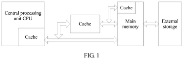
- FIG. 1 is an architecture diagram of a computer system according to an embodiment of the present invention.
- a cache is a small-capacity memory between a CPU and a main memory, and an access speed of the cache is quicker than that of the main memory, and is close to that of the CPU.
- the cache can provide an instruction and data for the CPU at a high speed, to improve an execution speed of a program.
- a cache technology is an important technology for resolving a problem of a speed mismatch between the CPU and the main memory.
- a cache is a buffer memory of a main memory, and includes a high-speed static random access memory SRAM.
- the cache may be built into a central processing unit CPU, or may be built into a memory, or the cache may be an independent entity externally existing between a CPU and a memory. All cache control logic is implemented by an internal cache controller.
- All cache control logic is implemented by an internal cache controller.
- semiconductor device integration constantly improves, currently a multi-level cache system with at least two levels of caches already emerges, such as an L1 cache (level 1 cache), an L2 cache (level 2 cache), and an L3 cache (level 3 cache).
- cache capacity is very small, content stored in the cache is only a subset of main memory content, and a data exchange between the CPU and the cache is in unit of word (word), but a data exchange between the cache and the main memory is in unit of cache line (cache line).
- One cache line includes multiple fixed-length words.
- the word is immediately transmitted from the cache to the CPU, or if the word currently does not exist in the cache, the word is read from the main memory in a main memory read period to send to the CPU, and an entire cache line that includes this word is read from the main memory to send to the cache.
- a cache line in the cache is replaced by using a specific replacement policy, and a replacement algorithm is implemented by a cache management logic circuit.
- a controller traverses all original cache lines to learn a quantity of access requests of each cache line or an access time interval of each cache line, so as to select a cache line with a minimum quantity of access requests or a longest access time interval, and delete the cache line while putting a new cache line into a cache.
- system overheads of the cache line replacement are relatively large, and efficiency is not high.
- An embodiment of the present invention provides a cache management method.
- the cache management method provided in this embodiment of the present invention in each cache line replacement process, there is no need to traverse all original cache lines, and there is no need to select a to-be-replaced cache line by means of calculation. This effectively reduces system overheads, and improves cache line replacement efficiency.
- the following describes, in detail by using a specific procedure in this embodiment of the present invention, a cache management method of the computer system shown in FIG. 1 . It may be understood that the cache management method in FIG. 2 may be applied to the cache shown in FIG. 1 .
- an embodiment of the cache management method in this embodiment of the present invention includes the following steps.
- a cache controller allocates a tag area to each cache line.
- the cache controller may allocate a data area and a tag area to each cache line.
- the data area may be used to store actual file data
- the tag area may be used to store a file number, an offset, length information, or data address information that is corresponding to the data area. Details are not described herein.
- a storage space size of each area in the data area may be dynamically changed or may be static.
- the cache controller may record a valid character length of the data area in the tag area, to dynamically change a storage space size of the data area. Details are not described herein.
- the cache controller may add an access count counter and an access time counter for each tag area.
- the access count counter may be used to collect statistics on a quantity of times that a cache line is accessed, and the access time counter may be used to record time at which the cache line is last accessed.
- the time may be identified by an absolute time value, or may be identified by a quantity of time periods. Details are not limited herein.
- the cache controller may collect statistics on an access count for each cache line, or may simultaneously collect statistics on the access count and access time for each cache line. Details are not limited herein.
- a cache may be built into a CPU, or may be built into a memory, or may be an independent entity.
- the entity may include a cache controller and a cache line, and composition of the cache line may include a static random access memory SRAM. Details are not limited herein.
- the cache controller obtains an access frequency count of each cache line.
- the cache controller may obtain the access frequency count of each cache line by detecting the tag area of each cache line.
- the access frequency count may include at least one of an access count or access time. Details are not limited herein.
- the access frequency count of each cache line may be obtained according to an access count of each cache line.
- the access count of a cache line may be used as an access frequency count of the cache line.
- the access frequency count of each cache line may be obtained according to an access count and access time of each cache line.
- an implementation in which the cache controller may adjust the access frequency count by using the access time may be as follows:
- the cache controller may update the access count or the access time of each cache line after the cache line is accessed.
- an access time update manner may be recording a current access time, or may be returning the access time counter to zero and restarting counting. Details are not limited herein.
- the cache controller determines an access frequency segment.
- the cache controller may determine multiple access frequency segments according to the access frequency count of each cache line in the cache and a preset division policy, and each access frequency segment may be corresponding to a different access frequency count range.
- the preset division policy may be as follows: The cache controller first determines a parameter upper limit value and a parameter lower limit value based on the access frequency count of each cache line.
- the parameter lower limit value may be 0, and the parameter upper limit value may be access times max.
- access times max may be a value preset by a user according to experience, or may be obtained by the cache controller by collecting statistics on the access frequency count of each cache line. Details are not limited herein.
- the cache controller may determine that the cache line does not need to be replaced.
- the cache controller may divide a range from the parameter lower limit value 0 to the parameter upper limit value access_times_max into N access frequency segments after determining the parameter upper limit value and the parameter lower limit value.
- the value N may be a value entered by the user in advance. It may be understood that, in actual application, a size of each access frequency segment may be a fixed value access_times_max/N, or may be a random value.
- the random value may be a value randomly generated by the cache controller, or may be a value entered by the user in advance. Details are not limited herein.
- the cache controller may further establish a data structure.
- the data structure is used to record a quantity of cache lines, in each access frequency segment, whose access frequency count belongs to the access frequency segment, or may establish a corresponding data structure for each access frequency segment. Details are not limited herein.
- the cache controller determines an access frequency segment to which each cache line belongs.
- the cache controller may determine, by traversing cache lines, a target access frequency count range to which the access frequency count of each cache line belongs, and determine a target access frequency segment corresponding to the target access frequency count range to which each cache line belongs. It should be noted that the cache controller may record, by using the data structure, a quantity of cache lines included in each access frequency segment, to collect statistics on the quantity of cache lines in the access frequency segment.
- the cache controller may correspondingly adjust a data structure corresponding to the access frequency segment. It may be understood that, in the actual application, each time determining that one cache line belongs to one access frequency segment, the cache controller may increase a quantity recorded by the data structure corresponding to the access frequency segment by a value 1.
- the cache controller determines a quantity M of to-be-replaced cache lines.
- the cache controller may pre-select M to-be-replaced cache lines according to an elimination ratio R.
- the to-be-replaced cache lines may be cache lines with a small access frequency count, and the quantity M of to-be-replaced cache lines may be a product of the elimination ratio R and a total quantity of cache lines, and M is an integer not less than 2.
- the elimination ratio R may be a fixed value, or may be dynamically adjusted by the cache controller. Details are not limited herein.
- the cache controller may determine, by monitoring an elimination frequency parameter in real time, whether the elimination frequency parameter exceeds a first threshold; and if the elimination frequency parameter exceeds the first threshold, the cache controller may adjust the elimination ratio R to an elimination ratio R1, or if the elimination frequency parameter does not exceed the first threshold, the cache controller may further determine whether the elimination frequency parameter is less than a second threshold. If the elimination frequency parameter is less than the second threshold, the cache controller may adjust the elimination ratio R to an elimination ratio R2. It should be noted that if the elimination frequency parameter is not less than the second threshold, the cache controller may continue to monitor the elimination frequency parameter.
- the first threshold and the second threshold may be values preset by a user, and the first threshold is less than the second threshold.
- the cache controller may increase the elimination ratio R by A to obtain the elimination ratio R1, or may decrease the elimination ratio R by A to obtain the elimination ratio R2.
- the value A may be a value preset by a user.
- the elimination frequency parameter may include at least one of a miss rate of each cache line in the cache or a traversal frequency of each cache line in the cache, and the cache controller may return to continue to monitor the elimination frequency parameter each time after adjusting the elimination ratio R.
- the cache controller determines a replacement set.
- the cache controller may successively accumulate a cache line in each access frequency segment into the replacement set in ascending order of values corresponding to an access frequency count range until a quantity of cache lines in the replacement set is equal to M. It may be understood that, in actual application, the accumulating, by the cache controller, a cache line in each access frequency segment may include the following steps:
- the cache controller may determine an access frequency segment whose value corresponding to an access frequency count range is lowest in an access frequency segment group as an accumulative access frequency segment, and the access frequency segment group includes each access frequency segment.
- the cache controller may remove the accumulative access frequency segment from the access frequency segment group.
- the cache controller may accumulate a cache line in the accumulative access frequency segment into the replacement set.
- the cache controller may determine whether a quantity of candidate cache lines in the replacement set is equal to M; and if the quantity of candidate cache lines in the replacement set is equal to M, the cache controller may end a procedure, or if the quantity of candidate cache lines in the replacement set is less than M, the cache controller may determine whether a next access frequency segment to be accumulated into the replacement set is a critical access frequency segment. If the next access frequency segment to be accumulated into the replacement set is not a critical access frequency segment, the cache controller may repeatedly perform steps 1 to 4; or if the next access frequency segment to be accumulated into the replacement set is a critical access frequency segment, the cache controller may randomly select, from the critical access frequency segment, X cache lines to accumulate into the replacement set.
- X may be a difference between M and a quantity of cache lines that have been accumulated into the replacement set.
- the critical access frequency segment is such an access frequency segment that before an included cache line of the access frequency segment is accumulated into the replacement set, the quantity of candidate cache lines in the replacement set is less than M and after the included cache line of the access frequency segment is accumulated into the replacement set, the quantity of candidate cache lines in the replacement set is greater than M.
- the cache controller may continue to traverse access frequency segments until the accumulative value is greater than or equal to M.
- the cache controller may first accumulate each access frequency segment into a set of to-be-eliminated range segments, and then may select, by traversing cache lines, a cache line that belongs to a to-be-eliminated access frequency segment.
- the cache controller may determine the replacement set by using the selected cache line as a cache line in the replacement set.
- the cache controller obtains an operation instruction.
- the cache controller may receive an operation instruction sent by a CPU.
- the operation instruction may carry a destination address, and the destination address may be an address that is in a memory and that is to be accessed in the operation instruction.
- the cache controller determines whether a destination address hits a cache line in a cache; and if the destination address hits a cache line in the cache, the cache controller performs step 209, or if the destination address hits no cache line in the cache, the cache controller performs step 210.
- a main memory address of the word may be sent to the cache and the main memory.
- the cache controller may determine, according to the address, whether the word currently exists in the cache. It should be noted that, in actual application, the cache controller may first match a cache line outside the replacement set, or may first match a cache line in the replacement set. Details are not limited herein.
- the cache controller updates an access frequency count.
- the cache controller may update an access frequency count of the cache line after the destination address hits a cache line in the cache.
- An update manner may be increasing a value of a counter for a tag area of the cache line.
- the cache controller may further monitor an access frequency count of a cache line in the replacement set in real time, and may eliminate, from the replacement set, a cache line whose access frequency count is greater than a third threshold within a preset time period.
- the third threshold may be 1.
- the cache controller may continue to monitor a quantity of times that the cache line in the replacement set is hit. If an access frequency count of a cache line in the replacement set is greater than the third threshold within a preset time period, the cache controller may consider that the cache line is hit by a destination address in a subsequently received operation instruction and may further be accessed, and therefore the cache line does not have to be eliminated. In this manner, the cache controller can update a cache line in the replacement set, to prevent some accessed cache lines from being incorrectly eliminated.
- the cache controller completes the step procedure after updating the access frequency count of the cache line.
- the cache controller stores, in the cache, a cache line obtained from the destination address.
- the cache controller may obtain the destination address from a storage medium after the destination address hits no cache line in the cache, and may write the cache line obtained from the destination address to replace a to-be-replaced cache line selected from the replacement set. It should be noted that, in actual application, the cache controller may first select, in ascending order of values corresponding to access frequency counts, a cache line with a small access frequency count from the replacement set as the to-be-replaced cache line.
- the cache controller completes the step procedure after writing the destination address to replace the to-be-replaced cache line in the replacement set.
- the cache includes 10 cache lines, and the cache controller may obtain the access frequency count of each cache line.
- the cache controller may determine a replacement set according to the access frequency count of each cache line in Table 1, and a process thereof is as follows:
- the cache controller determines that a lower limit value of the access frequency count is 0 and an upper limit value of the access frequency count is 30, and the cache controller determines that a cache line whose access frequency count is greater than the parameter upper limit 30 does not need to be eliminated.
- the cache controller may uniformly divide access frequency counts 0 to 30 into three access frequency segments (that is, a range segment #1 is 0 to 10, a range segment #2 is 11 to 20, and a range segment #3 is 21 to 30).
- the cache controller may obtain a quantity of cache lines in each access frequency segment by traversing cache lines. For details, refer to Table 2. Table 2 Range segment Range segment #1 Range segment #2 Range segment #3 Access frequency count 0 to 10 11 to 20 21 to 30 Quantity of cache lines 3 4 2 Cache line A1, A2, and A3 A4, A5, B1, and B2 B3 and B4
- the cache controller may determine that cache lines A1, A2, and A3 in the range segment #1 may be to-be-replaced cache lines, and the cache controller may determine that the range segment #2 is a critical access frequency segment.
- the cache controller may accumulate, in ascending order of values corresponding to an access frequency count range, to-be-eliminated cache lines as a replacement set, that is, successively select the cache lines A1, A2, A3, A4, and A5 as the replacement set.
- the cache controller may first select the to-be-replaced cache line A1 with a smallest access frequency count from the replacement set, and write the destination address read from the storage medium to replace the to-be-replaced cache line A1.
- the cache controller obtains the operation instruction.
- the operation instruction carries the destination address, and the destination address is the address that is in the memory and that is to be accessed in the operation instruction. If the destination address hits no cache line cache line in the cache, and the cache includes no idle cache line, the cache controller selects the to-be-replaced cache line from the replacement set.
- the replacement set includes at least two cache lines.
- the cache controller eliminates the to-be-replaced cache line from the cache; and the cache controller stores, in the cache, the cache line obtained from the memory according to the destination address. Therefore, in a cache line replacement process, the cache controller only needs to select the to-be-replaced cache line from the replacement set.
- the replacement set is pre-selected, and this effectively improves cache line replacement efficiency.
- the cache controller may directly determine the replacement set by using the access frequency count of each cache line.
- FIG. 3 another embodiment of a cache management method in this embodiment of the present invention includes the following steps.
- Steps 301 and 302 in this embodiment are the same as steps 201 and 202 in the embodiment shown in FIG. 2 , and details are not described herein.
- Step 303 in this embodiment is the same as step 205 in the embodiment shown in FIG. 2 , and details are not described herein again.
- the cache controller determines a replacement set.
- the cache controller may successively accumulate each cache line into the replacement set in ascending order of values corresponding to an access frequency count range until a quantity of to-be-replaced cache lines in the replacement set is equal to M, and the cache line accumulated into the replacement set is a to-be-replaced cache line.
- Steps 305 to 308 in this embodiment are the same as steps 207 to 210 in the embodiment shown in FIG. 2 , and details are not described herein again.
- FIG. 4 describes an apparatus embodiment corresponding to the method embodiment in FIG. 2 .
- an embodiment of the cache controller in this embodiment of the present invention includes:
- the second selection module 407 is specifically configured to successively select, in ascending order of access frequency count ranges corresponding to the multiple access frequency segments, a cache line that belongs to each access frequency segment until a quantity of selected cache lines is equal to M.
- the cache controller in this embodiment further includes: a third determining module 408, configured to determine the quantity M of to-be-replaced cache lines according to an elimination ratio R and a total quantity of cache lines in the cache, where M is a product of the elimination ratio R and the total quantity of cache lines.
- the adjustment module 410 is further configured to: when the elimination frequency parameter is less than a second threshold, adjust the elimination ratio R to an elimination ratio R2, where the elimination ratio R2 is less than the elimination ratio R, and the second threshold is less than the first threshold.
- the monitoring module 409 is specifically configured to monitor an access frequency count of a cache line that belongs to the replacement set.
- the elimination module 403 is specifically configured to eliminate, from the replacement set, a cache line whose access frequency count is greater than a third threshold within a preset time period.
- the obtaining module 401 obtains the operation instruction.
- the operation instruction carries the destination address, and the destination address is the address that is to be accessed in the operation instruction.
- the first selection module 402 selects the to-be-replaced cache line from the replacement set.
- the replacement set includes at least two cache lines.
- the elimination module 403 eliminates the to-be-replaced cache line from the cache.
- the storage module 404 stores, in the cache, the cache line obtained from the destination address. Therefore, in a cache line replacement process, the first selection module 402 only needs to select the to-be-replaced cache line from the replacement set.
- the replacement set is pre-selected, and this effectively improves cache line replacement efficiency.
- FIG. 5 another embodiment of a cache controller in this embodiment of the present invention includes:
- the cache controller in this embodiment further includes: a second selection module 505, configured to select, from cache lines in the cache, a to-be-replaced cache line according to a quantity M of to-be-replaced cache lines, to obtain the replacement set, where M is an integer not less than 2.
- the second selection module 505 in this embodiment is specifically configured to successively select a cache line in ascending order of access frequency count ranges corresponding to cache lines until a quantity of selected cache lines is equal to M.
- the cache controller in this embodiment further includes: a determining module 506, configured to determine the quantity M of to-be-replaced cache lines according to an elimination ratio R and a total quantity of cache lines in the cache, where M is a product of the elimination ratio R and the total quantity of cache lines.
- the adjustment module 508 is further configured to: when the elimination frequency parameter is less than a second threshold, adjust the elimination ratio R to an elimination ratio R2, where the elimination ratio R2 is less than the elimination ratio R, and the second threshold is less than the first threshold.
- the monitoring module 507 is specifically configured to monitor an access frequency count of a cache line that belongs to the replacement set.
- the elimination module 503 is specifically configured to eliminate, from the replacement set, a cache line whose access frequency count is greater than a third threshold within a preset time period.
- the obtaining module 501 obtains the operation instruction.
- the operation instruction carries the destination address, and the destination address is the address that is to be accessed in the operation instruction.
- the first selection module 502 selects the to-be-replaced cache line from the replacement set.
- the replacement set includes at least two cache lines.
- the elimination module 503 eliminates the to-be-replaced cache line from the cache.
- the storage module 504 stores, in the cache, the cache line obtained from the destination address. Therefore, in a cache line replacement process, the selection module 502 only needs to select the to-be-replaced cache line from the replacement set.
- the replacement set is pre-selected, and this effectively improves cache line replacement efficiency.
- an embodiment of the computer system in this embodiment of the present invention includes a processor 601, a cache 602, a cache controller 603, and a memory 604.
- the cache 602 is configured to cache some data in the memory 604.
- the processor 601 is configured to send an operation instruction; and the cache controller 603 is configured to:
- the cache controller 603 is further configured to perform the following steps:
- the cache controller 603 is further configured to perform the following step: successively selecting, in ascending order of access frequency count ranges corresponding to the multiple access frequency segments, a cache line that belongs to each access frequency segment until a quantity of selected cache lines is equal to M.
- the cache controller 603 is further configured to perform the following steps:
- the cache controller 603 is further configured to perform the following steps:
- An embodiment of the present invention further provides a computer program product for implementing an access request processing method, including a computer readable storage medium that stores program code, where an instruction included in the program code is used to execute the method procedure described in any one of the foregoing method embodiments.
- a computer readable storage medium that stores program code, where an instruction included in the program code is used to execute the method procedure described in any one of the foregoing method embodiments.
- the foregoing storage medium may include any non-transitory (non-transitory) machine-readable medium capable of storing program code, such as a USB flash drive, a removable hard disk, a magnetic disk, an optical disc, a random-access memory (Random-Access Memory, RAM), a solid state disk (Solid State Disk, SSD), or another non-volatile memory (non-volatile memory).
Landscapes
- Engineering & Computer Science (AREA)
- Theoretical Computer Science (AREA)
- Physics & Mathematics (AREA)
- General Engineering & Computer Science (AREA)
- General Physics & Mathematics (AREA)
- Human Computer Interaction (AREA)
- Memory System Of A Hierarchy Structure (AREA)
Applications Claiming Priority (1)
| Application Number | Priority Date | Filing Date | Title |
|---|---|---|---|
| PCT/CN2016/070230 WO2017117734A1 (fr) | 2016-01-06 | 2016-01-06 | Procédé de gestion d'antémémoire, contrôleur d'antémémoire et système informatique |
Publications (3)
| Publication Number | Publication Date |
|---|---|
| EP3388935A1 true EP3388935A1 (fr) | 2018-10-17 |
| EP3388935A4 EP3388935A4 (fr) | 2018-12-19 |
| EP3388935B1 EP3388935B1 (fr) | 2021-09-29 |
Family
ID=59273134
Family Applications (1)
| Application Number | Title | Priority Date | Filing Date |
|---|---|---|---|
| EP16882879.6A Active EP3388935B1 (fr) | 2016-01-06 | 2016-01-06 | Procédé de gestion d'antémémoire, contrôleur d'antémémoire et système informatique |
Country Status (4)
| Country | Link |
|---|---|
| US (1) | US10831677B2 (fr) |
| EP (1) | EP3388935B1 (fr) |
| CN (1) | CN108139872B (fr) |
| WO (1) | WO2017117734A1 (fr) |
Families Citing this family (16)
| Publication number | Priority date | Publication date | Assignee | Title |
|---|---|---|---|---|
| US10845995B2 (en) * | 2017-06-30 | 2020-11-24 | Intel Corporation | Techniques to control an insertion ratio for a cache |
| CN109408411A (zh) * | 2018-09-25 | 2019-03-01 | 浙江工商大学 | 基于数据访问次数的GPGPU的L1 Cache管理方法 |
| US10824567B2 (en) * | 2018-12-04 | 2020-11-03 | International Business Machines Corporation | Selectively preventing pre-coherence point reads in a cache hierarchy to reduce barrier overhead |
| CN110519181B (zh) * | 2019-07-23 | 2022-09-06 | 中国航空无线电电子研究所 | 基于跨频段时间触发通信的交换方法 |
| CN111221749A (zh) * | 2019-11-15 | 2020-06-02 | 新华三半导体技术有限公司 | 数据块写入方法、装置、处理器芯片及Cache |
| US11768779B2 (en) * | 2019-12-16 | 2023-09-26 | Advanced Micro Devices, Inc. | Cache management based on access type priority |
| CN114157621A (zh) * | 2020-09-07 | 2022-03-08 | 华为技术有限公司 | 一种发送清除报文的方法及装置 |
| WO2022178869A1 (fr) * | 2021-02-26 | 2022-09-01 | 华为技术有限公司 | Procédé et appareil de remplacement de mémoire cache |
| CN113177069B (zh) * | 2021-05-08 | 2024-07-09 | 中国科学院声学研究所 | 一种高速缓存与查询系统及查询方法 |
| CN113282523B (zh) * | 2021-05-08 | 2022-09-30 | 重庆大学 | 一种缓存分片的动态调整方法、装置以及存储介质 |
| CN113778912B (zh) * | 2021-08-25 | 2024-05-07 | 深圳市中科蓝讯科技股份有限公司 | cache映射架构动态调整方法及cache控制器 |
| CN119292962B (zh) * | 2022-03-02 | 2025-07-15 | 华为技术有限公司 | 共享缓存的管理方法、装置及存储介质 |
| GB2626756A (en) | 2023-02-01 | 2024-08-07 | Ibm | Maintaining cache validity |
| CN117130663B (zh) * | 2023-09-19 | 2024-06-11 | 摩尔线程智能科技(北京)有限责任公司 | 一种指令读取方法及l2指令缓存、电子设备和存储介质 |
| US12455830B2 (en) | 2023-09-29 | 2025-10-28 | Advanced Micro Devices, Inc. | Efficient cache data storage for iterative workloads |
| CN119271573B (zh) * | 2024-12-11 | 2025-04-22 | 鼎道智芯(上海)半导体有限公司 | 一种缓存数据处理方法及装置 |
Family Cites Families (31)
| Publication number | Priority date | Publication date | Assignee | Title |
|---|---|---|---|---|
| JPH09212421A (ja) * | 1996-02-01 | 1997-08-15 | Hitachi Ltd | データ処理装置及びデータ処理システム |
| US7133971B2 (en) * | 2003-11-21 | 2006-11-07 | International Business Machines Corporation | Cache with selective least frequently used or most frequently used cache line replacement |
| US6813691B2 (en) * | 2001-10-31 | 2004-11-02 | Hewlett-Packard Development Company, L.P. | Computer performance improvement by adjusting a count used for preemptive eviction of cache entries |
| US7284095B2 (en) * | 2004-08-18 | 2007-10-16 | International Business Machines Corporation | Latency-aware replacement system and method for cache memories |
| US7546417B1 (en) * | 2008-07-15 | 2009-06-09 | International Business Machines Corporation | Method and system for reducing cache tag bits |
| US8996812B2 (en) * | 2009-06-19 | 2015-03-31 | International Business Machines Corporation | Write-back coherency data cache for resolving read/write conflicts |
| US8712984B2 (en) * | 2010-03-04 | 2014-04-29 | Microsoft Corporation | Buffer pool extension for database server |
| US8914582B1 (en) * | 2011-11-14 | 2014-12-16 | Google Inc. | Systems and methods for pinning content in cache |
| US8688915B2 (en) * | 2011-12-09 | 2014-04-01 | International Business Machines Corporation | Weighted history allocation predictor algorithm in a hybrid cache |
| US8843707B2 (en) * | 2011-12-09 | 2014-09-23 | International Business Machines Corporation | Dynamic inclusive policy in a hybrid cache hierarchy using bandwidth |
| US9767032B2 (en) * | 2012-01-12 | 2017-09-19 | Sandisk Technologies Llc | Systems and methods for cache endurance |
| CN104077242B (zh) * | 2013-03-25 | 2017-03-29 | 华为技术有限公司 | 一种缓存管理方法和装置 |
| CN104123243B (zh) * | 2013-04-24 | 2018-08-03 | 鸿富锦精密电子(天津)有限公司 | 数据缓存系统及方法 |
| CN103246616B (zh) * | 2013-05-24 | 2017-09-26 | 浪潮电子信息产业股份有限公司 | 一种长短周期访问频度的全局共享缓存替换方法 |
| US10133678B2 (en) * | 2013-08-28 | 2018-11-20 | Advanced Micro Devices, Inc. | Method and apparatus for memory management |
| CN103873562A (zh) * | 2014-02-27 | 2014-06-18 | 车智互联(北京)科技有限公司 | 缓存方法和缓存系统 |
| CN105094686B (zh) * | 2014-05-09 | 2018-04-10 | 华为技术有限公司 | 数据缓存方法、缓存和计算机系统 |
| CN104156322B (zh) * | 2014-08-05 | 2017-10-17 | 华为技术有限公司 | 一种缓存管理方法及缓存管理装置 |
| US20160062916A1 (en) * | 2014-08-27 | 2016-03-03 | The Board Trustees Of The Leland Stanford Junior University | Circuit-based apparatuses and methods with probabilistic cache eviction or replacement |
| US9405706B2 (en) * | 2014-09-25 | 2016-08-02 | Intel Corporation | Instruction and logic for adaptive dataset priorities in processor caches |
| US9965394B2 (en) * | 2014-12-23 | 2018-05-08 | EMC IP Holding Company LLC | Selective compression in data storage systems |
| US9892045B1 (en) * | 2015-01-30 | 2018-02-13 | EMC IP Holding Company LLC | Methods to select segments of an evicted cache unit for reinsertion into the cache |
| US9720835B1 (en) * | 2015-01-30 | 2017-08-01 | EMC IP Holding Company LLC | Methods to efficiently implement coarse granularity cache eviction based on segment deletion hints |
| US9892044B1 (en) * | 2015-01-30 | 2018-02-13 | EMC IP Holding Company LLC | Methods to efficiently implement coarse granularity cache eviction |
| US9921963B1 (en) * | 2015-01-30 | 2018-03-20 | EMC IP Holding Company LLC | Method to decrease computation for cache eviction using deferred calculations |
| JP2016170682A (ja) * | 2015-03-13 | 2016-09-23 | 富士通株式会社 | 演算処理装置及び演算処理装置の制御方法 |
| US9983996B2 (en) * | 2015-12-10 | 2018-05-29 | Intel Corporation | Technologies for managing cache memory in a distributed shared memory compute system |
| US10185666B2 (en) * | 2015-12-15 | 2019-01-22 | Facebook, Inc. | Item-wise simulation in a block cache where data eviction places data into comparable score in comparable section in the block cache |
| US10496551B2 (en) * | 2017-06-28 | 2019-12-03 | Intel Corporation | Method and system for leveraging non-uniform miss penality in cache replacement policy to improve processor performance and power |
| US20190087344A1 (en) * | 2017-09-20 | 2019-03-21 | Qualcomm Incorporated | Reducing Clean Evictions In An Exclusive Cache Memory Hierarchy |
| US10585798B2 (en) * | 2017-11-27 | 2020-03-10 | Intel Corporation | Tracking cache line consumption |
-
2016
- 2016-01-06 WO PCT/CN2016/070230 patent/WO2017117734A1/fr not_active Ceased
- 2016-01-06 EP EP16882879.6A patent/EP3388935B1/fr active Active
- 2016-01-06 CN CN201680059005.9A patent/CN108139872B/zh active Active
-
2018
- 2018-07-05 US US16/028,265 patent/US10831677B2/en active Active
Also Published As
| Publication number | Publication date |
|---|---|
| WO2017117734A1 (fr) | 2017-07-13 |
| EP3388935B1 (fr) | 2021-09-29 |
| CN108139872B (zh) | 2020-07-07 |
| US10831677B2 (en) | 2020-11-10 |
| CN108139872A (zh) | 2018-06-08 |
| US20180314646A1 (en) | 2018-11-01 |
| EP3388935A4 (fr) | 2018-12-19 |
Similar Documents
| Publication | Publication Date | Title |
|---|---|---|
| US10831677B2 (en) | Cache management method, cache controller, and computer system | |
| JP6613375B2 (ja) | プロファイリングキャッシュ置換 | |
| US11099997B2 (en) | Data prefetching method and apparatus, and storage device | |
| US9501420B2 (en) | Cache optimization technique for large working data sets | |
| US10133679B2 (en) | Read cache management method and apparatus based on solid state drive | |
| US8176258B2 (en) | System and method for cache management | |
| US10296466B2 (en) | Information processing device, method of controlling a cache memory, and storage medium | |
| CN108763110B (zh) | 一种数据缓存方法及装置 | |
| US9734066B1 (en) | Workload-based adjustable cache size | |
| US8572325B2 (en) | Dynamic adjustment of read/write ratio of a disk cache | |
| TW201432451A (zh) | 用於改善輸入輸出效能之調節資料快取速率之方法 | |
| JP2014535106A (ja) | ストレージ・システムの二次キャッシュ内にデータをポピュレートするための方法、制御装置、プログラム | |
| US11461239B2 (en) | Method and apparatus for buffering data blocks, computer device, and computer-readable storage medium | |
| KR20200057311A (ko) | 통신되는 데이터의 양을 동작의 중단 빈도에 따라 스로틀링하는 스토리지 장치 | |
| CN116467353B (zh) | 一种基于lru差异化的自适应调节的缓存方法及系统 | |
| CN104077241B (zh) | 缓存淘汰算法切换处理方法及装置 | |
| US11281587B2 (en) | Self-tuning cache | |
| JP2017162194A (ja) | データ管理プログラム、データ管理装置、及びデータ管理方法 | |
| KR20190106271A (ko) | 메모리 시스템 및 그것의 동작 방법 | |
| US6978349B1 (en) | Adaptive cache memory management | |
| CN105573675B (zh) | 缓存管理装置中基于训练机制的用户习惯获取方法及装置 | |
| JP3751814B2 (ja) | キャッシュメモリ制御方式 | |
| US20190042613A1 (en) | Storage architectures for graph analysis applications | |
| JP2017058904A (ja) | キャッシュ装置およびキャッシュ装置の制御方法 | |
| CN119225660A (zh) | 一种自适应nand闪存的页面替换方法及系统 |
Legal Events
| Date | Code | Title | Description |
|---|---|---|---|
| STAA | Information on the status of an ep patent application or granted ep patent |
Free format text: STATUS: THE INTERNATIONAL PUBLICATION HAS BEEN MADE |
|
| PUAI | Public reference made under article 153(3) epc to a published international application that has entered the european phase |
Free format text: ORIGINAL CODE: 0009012 |
|
| STAA | Information on the status of an ep patent application or granted ep patent |
Free format text: STATUS: REQUEST FOR EXAMINATION WAS MADE |
|
| 17P | Request for examination filed |
Effective date: 20180712 |
|
| AK | Designated contracting states |
Kind code of ref document: A1 Designated state(s): AL AT BE BG CH CY CZ DE DK EE ES FI FR GB GR HR HU IE IS IT LI LT LU LV MC MK MT NL NO PL PT RO RS SE SI SK SM TR |
|
| AX | Request for extension of the european patent |
Extension state: BA ME |
|
| REG | Reference to a national code |
Ref country code: DE Ref legal event code: R079 Ref document number: 602016064485 Country of ref document: DE Free format text: PREVIOUS MAIN CLASS: G06F0003060000 Ipc: G06F0012122000 |
|
| A4 | Supplementary search report drawn up and despatched |
Effective date: 20181119 |
|
| RIC1 | Information provided on ipc code assigned before grant |
Ipc: G06F 3/06 20060101ALI20181112BHEP Ipc: G06F 12/122 20160101AFI20181112BHEP Ipc: G06F 12/0804 20160101ALI20181112BHEP Ipc: G06F 12/121 20160101ALI20181112BHEP Ipc: G06F 12/0871 20160101ALI20181112BHEP |
|
| DAV | Request for validation of the european patent (deleted) | ||
| DAX | Request for extension of the european patent (deleted) | ||
| STAA | Information on the status of an ep patent application or granted ep patent |
Free format text: STATUS: EXAMINATION IS IN PROGRESS |
|
| 17Q | First examination report despatched |
Effective date: 20190903 |
|
| GRAP | Despatch of communication of intention to grant a patent |
Free format text: ORIGINAL CODE: EPIDOSNIGR1 |
|
| STAA | Information on the status of an ep patent application or granted ep patent |
Free format text: STATUS: GRANT OF PATENT IS INTENDED |
|
| INTG | Intention to grant announced |
Effective date: 20210420 |
|
| GRAS | Grant fee paid |
Free format text: ORIGINAL CODE: EPIDOSNIGR3 |
|
| GRAA | (expected) grant |
Free format text: ORIGINAL CODE: 0009210 |
|
| STAA | Information on the status of an ep patent application or granted ep patent |
Free format text: STATUS: THE PATENT HAS BEEN GRANTED |
|
| AK | Designated contracting states |
Kind code of ref document: B1 Designated state(s): AL AT BE BG CH CY CZ DE DK EE ES FI FR GB GR HR HU IE IS IT LI LT LU LV MC MK MT NL NO PL PT RO RS SE SI SK SM TR |
|
| REG | Reference to a national code |
Ref country code: GB Ref legal event code: FG4D |
|
| REG | Reference to a national code |
Ref country code: CH Ref legal event code: EP Ref country code: AT Ref legal event code: REF Ref document number: 1434820 Country of ref document: AT Kind code of ref document: T Effective date: 20211015 |
|
| REG | Reference to a national code |
Ref country code: DE Ref legal event code: R096 Ref document number: 602016064485 Country of ref document: DE |
|
| REG | Reference to a national code |
Ref country code: IE Ref legal event code: FG4D |
|
| REG | Reference to a national code |
Ref country code: LT Ref legal event code: MG9D |
|
| PG25 | Lapsed in a contracting state [announced via postgrant information from national office to epo] |
Ref country code: LT Free format text: LAPSE BECAUSE OF FAILURE TO SUBMIT A TRANSLATION OF THE DESCRIPTION OR TO PAY THE FEE WITHIN THE PRESCRIBED TIME-LIMIT Effective date: 20210929 Ref country code: BG Free format text: LAPSE BECAUSE OF FAILURE TO SUBMIT A TRANSLATION OF THE DESCRIPTION OR TO PAY THE FEE WITHIN THE PRESCRIBED TIME-LIMIT Effective date: 20211229 Ref country code: NO Free format text: LAPSE BECAUSE OF FAILURE TO SUBMIT A TRANSLATION OF THE DESCRIPTION OR TO PAY THE FEE WITHIN THE PRESCRIBED TIME-LIMIT Effective date: 20211229 Ref country code: FI Free format text: LAPSE BECAUSE OF FAILURE TO SUBMIT A TRANSLATION OF THE DESCRIPTION OR TO PAY THE FEE WITHIN THE PRESCRIBED TIME-LIMIT Effective date: 20210929 Ref country code: HR Free format text: LAPSE BECAUSE OF FAILURE TO SUBMIT A TRANSLATION OF THE DESCRIPTION OR TO PAY THE FEE WITHIN THE PRESCRIBED TIME-LIMIT Effective date: 20210929 Ref country code: RS Free format text: LAPSE BECAUSE OF FAILURE TO SUBMIT A TRANSLATION OF THE DESCRIPTION OR TO PAY THE FEE WITHIN THE PRESCRIBED TIME-LIMIT Effective date: 20210929 Ref country code: SE Free format text: LAPSE BECAUSE OF FAILURE TO SUBMIT A TRANSLATION OF THE DESCRIPTION OR TO PAY THE FEE WITHIN THE PRESCRIBED TIME-LIMIT Effective date: 20210929 |
|
| REG | Reference to a national code |
Ref country code: NL Ref legal event code: MP Effective date: 20210929 |
|
| REG | Reference to a national code |
Ref country code: AT Ref legal event code: MK05 Ref document number: 1434820 Country of ref document: AT Kind code of ref document: T Effective date: 20210929 |
|
| PG25 | Lapsed in a contracting state [announced via postgrant information from national office to epo] |
Ref country code: LV Free format text: LAPSE BECAUSE OF FAILURE TO SUBMIT A TRANSLATION OF THE DESCRIPTION OR TO PAY THE FEE WITHIN THE PRESCRIBED TIME-LIMIT Effective date: 20210929 Ref country code: GR Free format text: LAPSE BECAUSE OF FAILURE TO SUBMIT A TRANSLATION OF THE DESCRIPTION OR TO PAY THE FEE WITHIN THE PRESCRIBED TIME-LIMIT Effective date: 20211230 |
|
| PG25 | Lapsed in a contracting state [announced via postgrant information from national office to epo] |
Ref country code: AT Free format text: LAPSE BECAUSE OF FAILURE TO SUBMIT A TRANSLATION OF THE DESCRIPTION OR TO PAY THE FEE WITHIN THE PRESCRIBED TIME-LIMIT Effective date: 20210929 |
|
| PG25 | Lapsed in a contracting state [announced via postgrant information from national office to epo] |
Ref country code: IS Free format text: LAPSE BECAUSE OF FAILURE TO SUBMIT A TRANSLATION OF THE DESCRIPTION OR TO PAY THE FEE WITHIN THE PRESCRIBED TIME-LIMIT Effective date: 20220129 Ref country code: SK Free format text: LAPSE BECAUSE OF FAILURE TO SUBMIT A TRANSLATION OF THE DESCRIPTION OR TO PAY THE FEE WITHIN THE PRESCRIBED TIME-LIMIT Effective date: 20210929 Ref country code: RO Free format text: LAPSE BECAUSE OF FAILURE TO SUBMIT A TRANSLATION OF THE DESCRIPTION OR TO PAY THE FEE WITHIN THE PRESCRIBED TIME-LIMIT Effective date: 20210929 Ref country code: PT Free format text: LAPSE BECAUSE OF FAILURE TO SUBMIT A TRANSLATION OF THE DESCRIPTION OR TO PAY THE FEE WITHIN THE PRESCRIBED TIME-LIMIT Effective date: 20220131 Ref country code: PL Free format text: LAPSE BECAUSE OF FAILURE TO SUBMIT A TRANSLATION OF THE DESCRIPTION OR TO PAY THE FEE WITHIN THE PRESCRIBED TIME-LIMIT Effective date: 20210929 Ref country code: NL Free format text: LAPSE BECAUSE OF FAILURE TO SUBMIT A TRANSLATION OF THE DESCRIPTION OR TO PAY THE FEE WITHIN THE PRESCRIBED TIME-LIMIT Effective date: 20210929 Ref country code: ES Free format text: LAPSE BECAUSE OF FAILURE TO SUBMIT A TRANSLATION OF THE DESCRIPTION OR TO PAY THE FEE WITHIN THE PRESCRIBED TIME-LIMIT Effective date: 20210929 Ref country code: EE Free format text: LAPSE BECAUSE OF FAILURE TO SUBMIT A TRANSLATION OF THE DESCRIPTION OR TO PAY THE FEE WITHIN THE PRESCRIBED TIME-LIMIT Effective date: 20210929 Ref country code: CZ Free format text: LAPSE BECAUSE OF FAILURE TO SUBMIT A TRANSLATION OF THE DESCRIPTION OR TO PAY THE FEE WITHIN THE PRESCRIBED TIME-LIMIT Effective date: 20210929 Ref country code: AL Free format text: LAPSE BECAUSE OF FAILURE TO SUBMIT A TRANSLATION OF THE DESCRIPTION OR TO PAY THE FEE WITHIN THE PRESCRIBED TIME-LIMIT Effective date: 20210929 |
|
| REG | Reference to a national code |
Ref country code: DE Ref legal event code: R097 Ref document number: 602016064485 Country of ref document: DE |
|
| PG25 | Lapsed in a contracting state [announced via postgrant information from national office to epo] |
Ref country code: DK Free format text: LAPSE BECAUSE OF FAILURE TO SUBMIT A TRANSLATION OF THE DESCRIPTION OR TO PAY THE FEE WITHIN THE PRESCRIBED TIME-LIMIT Effective date: 20210929 |
|
| PLBE | No opposition filed within time limit |
Free format text: ORIGINAL CODE: 0009261 |
|
| STAA | Information on the status of an ep patent application or granted ep patent |
Free format text: STATUS: NO OPPOSITION FILED WITHIN TIME LIMIT |
|
| PG25 | Lapsed in a contracting state [announced via postgrant information from national office to epo] |
Ref country code: MC Free format text: LAPSE BECAUSE OF FAILURE TO SUBMIT A TRANSLATION OF THE DESCRIPTION OR TO PAY THE FEE WITHIN THE PRESCRIBED TIME-LIMIT Effective date: 20210929 |
|
| REG | Reference to a national code |
Ref country code: CH Ref legal event code: PL |
|
| 26N | No opposition filed |
Effective date: 20220630 |
|
| REG | Reference to a national code |
Ref country code: BE Ref legal event code: MM Effective date: 20220131 |
|
| PG25 | Lapsed in a contracting state [announced via postgrant information from national office to epo] |
Ref country code: LU Free format text: LAPSE BECAUSE OF NON-PAYMENT OF DUE FEES Effective date: 20220106 |
|
| PG25 | Lapsed in a contracting state [announced via postgrant information from national office to epo] |
Ref country code: SI Free format text: LAPSE BECAUSE OF FAILURE TO SUBMIT A TRANSLATION OF THE DESCRIPTION OR TO PAY THE FEE WITHIN THE PRESCRIBED TIME-LIMIT Effective date: 20210929 Ref country code: BE Free format text: LAPSE BECAUSE OF NON-PAYMENT OF DUE FEES Effective date: 20220131 |
|
| PG25 | Lapsed in a contracting state [announced via postgrant information from national office to epo] |
Ref country code: LI Free format text: LAPSE BECAUSE OF NON-PAYMENT OF DUE FEES Effective date: 20220131 Ref country code: CH Free format text: LAPSE BECAUSE OF NON-PAYMENT OF DUE FEES Effective date: 20220131 |
|
| PG25 | Lapsed in a contracting state [announced via postgrant information from national office to epo] |
Ref country code: IT Free format text: LAPSE BECAUSE OF FAILURE TO SUBMIT A TRANSLATION OF THE DESCRIPTION OR TO PAY THE FEE WITHIN THE PRESCRIBED TIME-LIMIT Effective date: 20210929 Ref country code: IE Free format text: LAPSE BECAUSE OF NON-PAYMENT OF DUE FEES Effective date: 20220106 |
|
| PG25 | Lapsed in a contracting state [announced via postgrant information from national office to epo] |
Ref country code: HU Free format text: LAPSE BECAUSE OF FAILURE TO SUBMIT A TRANSLATION OF THE DESCRIPTION OR TO PAY THE FEE WITHIN THE PRESCRIBED TIME-LIMIT; INVALID AB INITIO Effective date: 20160106 |
|
| PG25 | Lapsed in a contracting state [announced via postgrant information from national office to epo] |
Ref country code: SM Free format text: LAPSE BECAUSE OF FAILURE TO SUBMIT A TRANSLATION OF THE DESCRIPTION OR TO PAY THE FEE WITHIN THE PRESCRIBED TIME-LIMIT Effective date: 20210929 Ref country code: MK Free format text: LAPSE BECAUSE OF FAILURE TO SUBMIT A TRANSLATION OF THE DESCRIPTION OR TO PAY THE FEE WITHIN THE PRESCRIBED TIME-LIMIT Effective date: 20210929 Ref country code: CY Free format text: LAPSE BECAUSE OF FAILURE TO SUBMIT A TRANSLATION OF THE DESCRIPTION OR TO PAY THE FEE WITHIN THE PRESCRIBED TIME-LIMIT Effective date: 20210929 |
|
| PG25 | Lapsed in a contracting state [announced via postgrant information from national office to epo] |
Ref country code: MT Free format text: LAPSE BECAUSE OF FAILURE TO SUBMIT A TRANSLATION OF THE DESCRIPTION OR TO PAY THE FEE WITHIN THE PRESCRIBED TIME-LIMIT Effective date: 20210929 |
|
| PG25 | Lapsed in a contracting state [announced via postgrant information from national office to epo] |
Ref country code: TR Free format text: LAPSE BECAUSE OF FAILURE TO SUBMIT A TRANSLATION OF THE DESCRIPTION OR TO PAY THE FEE WITHIN THE PRESCRIBED TIME-LIMIT Effective date: 20210929 |
|
| PGFP | Annual fee paid to national office [announced via postgrant information from national office to epo] |
Ref country code: GB Payment date: 20251204 Year of fee payment: 11 |
|
| PGFP | Annual fee paid to national office [announced via postgrant information from national office to epo] |
Ref country code: FR Payment date: 20251208 Year of fee payment: 11 |
|
| PGFP | Annual fee paid to national office [announced via postgrant information from national office to epo] |
Ref country code: DE Payment date: 20251203 Year of fee payment: 11 |