EP3388976B1 - Betrugserkennungsverfahren - Google Patents
Betrugserkennungsverfahren Download PDFInfo
- Publication number
- EP3388976B1 EP3388976B1 EP18166590.2A EP18166590A EP3388976B1 EP 3388976 B1 EP3388976 B1 EP 3388976B1 EP 18166590 A EP18166590 A EP 18166590A EP 3388976 B1 EP3388976 B1 EP 3388976B1
- Authority
- EP
- European Patent Office
- Prior art keywords
- body part
- image
- light
- led
- finger
- Prior art date
- Legal status (The legal status is an assumption and is not a legal conclusion. Google has not performed a legal analysis and makes no representation as to the accuracy of the status listed.)
- Active
Links
Images



Classifications
-
- G—PHYSICS
- G06—COMPUTING OR CALCULATING; COUNTING
- G06V—IMAGE OR VIDEO RECOGNITION OR UNDERSTANDING
- G06V40/00—Recognition of biometric, human-related or animal-related patterns in image or video data
- G06V40/10—Human or animal bodies, e.g. vehicle occupants or pedestrians; Body parts, e.g. hands
- G06V40/12—Fingerprints or palmprints
- G06V40/1382—Detecting the live character of the finger, i.e. distinguishing from a fake or cadaver finger
- G06V40/1394—Detecting the live character of the finger, i.e. distinguishing from a fake or cadaver finger using acquisition arrangements
-
- G—PHYSICS
- G06—COMPUTING OR CALCULATING; COUNTING
- G06V—IMAGE OR VIDEO RECOGNITION OR UNDERSTANDING
- G06V40/00—Recognition of biometric, human-related or animal-related patterns in image or video data
- G06V40/40—Spoof detection, e.g. liveness detection
-
- G—PHYSICS
- G06—COMPUTING OR CALCULATING; COUNTING
- G06V—IMAGE OR VIDEO RECOGNITION OR UNDERSTANDING
- G06V10/00—Arrangements for image or video recognition or understanding
- G06V10/10—Image acquisition
- G06V10/12—Details of acquisition arrangements; Constructional details thereof
- G06V10/14—Optical characteristics of the device performing the acquisition or on the illumination arrangements
- G06V10/141—Control of illumination
-
- G—PHYSICS
- G06—COMPUTING OR CALCULATING; COUNTING
- G06V—IMAGE OR VIDEO RECOGNITION OR UNDERSTANDING
- G06V10/00—Arrangements for image or video recognition or understanding
- G06V10/10—Image acquisition
- G06V10/12—Details of acquisition arrangements; Constructional details thereof
- G06V10/14—Optical characteristics of the device performing the acquisition or on the illumination arrangements
- G06V10/143—Sensing or illuminating at different wavelengths
-
- G—PHYSICS
- G06—COMPUTING OR CALCULATING; COUNTING
- G06V—IMAGE OR VIDEO RECOGNITION OR UNDERSTANDING
- G06V40/00—Recognition of biometric, human-related or animal-related patterns in image or video data
- G06V40/10—Human or animal bodies, e.g. vehicle occupants or pedestrians; Body parts, e.g. hands
- G06V40/12—Fingerprints or palmprints
- G06V40/13—Sensors therefor
-
- G—PHYSICS
- G06—COMPUTING OR CALCULATING; COUNTING
- G06V—IMAGE OR VIDEO RECOGNITION OR UNDERSTANDING
- G06V40/00—Recognition of biometric, human-related or animal-related patterns in image or video data
- G06V40/10—Human or animal bodies, e.g. vehicle occupants or pedestrians; Body parts, e.g. hands
- G06V40/12—Fingerprints or palmprints
- G06V40/13—Sensors therefor
- G06V40/1318—Sensors therefor using electro-optical elements or layers, e.g. electroluminescent sensing
-
- G—PHYSICS
- G06—COMPUTING OR CALCULATING; COUNTING
- G06V—IMAGE OR VIDEO RECOGNITION OR UNDERSTANDING
- G06V40/00—Recognition of biometric, human-related or animal-related patterns in image or video data
- G06V40/10—Human or animal bodies, e.g. vehicle occupants or pedestrians; Body parts, e.g. hands
- G06V40/12—Fingerprints or palmprints
- G06V40/1365—Matching; Classification
-
- G—PHYSICS
- G06—COMPUTING OR CALCULATING; COUNTING
- G06V—IMAGE OR VIDEO RECOGNITION OR UNDERSTANDING
- G06V40/00—Recognition of biometric, human-related or animal-related patterns in image or video data
- G06V40/10—Human or animal bodies, e.g. vehicle occupants or pedestrians; Body parts, e.g. hands
- G06V40/12—Fingerprints or palmprints
- G06V40/1341—Sensing with light passing through the finger
Definitions
- the invention relates to a method for detecting fraud during use of a device for capturing an imprint of a body part using a principle of total dark-field reflection.
- fingerprints for example of the fingerprint type, of a plurality of fingers, of a palm of the hand, makes it possible to secure access to buildings or to machines. Using this technology makes it possible to reinforce security insofar as the probability that two people have two identical fingerprints is almost zero.
- a fingerprint capture device captures an image of a fingerprint.
- this fingerprint is compared with a set of reference fingerprints contained in a database.
- this fingerprint is compared to a single fingerprint. The comparison makes it possible to determine whether or not the captured fingerprint belongs to a person referenced in the database or whether the person is indeed who he claims to be.
- Some ill-intentioned individuals attempt to be identified (respectively authenticated) fraudulently by using decoys in order to mislead identification (respectively authentication) devices.
- the document FR3015728 describes a method for validating that a bodily element such as a lower surface of one or more fingers or the palm of a hand is covered with real skin.
- the principle consists more precisely in illuminating the surface of the element using a light source making it possible to illuminate only an area, called the illuminated area, well defined on the element and to maintain an area without direct illumination. , called the diffusion zone.
- An image of these two areas is then captured and analyzed to deduce therefrom that said element is covered with real skin or fake skin.
- an analysis zone covering the illuminated zone and the diffusion zone is divided into several calculation zones.
- An average luminous intensity of the pixels is then calculated for each calculation zone, which makes it possible to obtain a curve of luminous intensity and a curve of the gradient of luminous intensity according to the distance from the calculation zone to the limit of the illuminated area and to compare the characteristics of these curves with those extracted from reference curves.
- the invention relates to the fraud detection method as defined in claim 1.
- the invention relates to a device comprising means for implementing the method according to the first aspect.
- the invention relates to equipment comprising a device according to the second aspect.
- the invention relates to a computer program, comprising instructions for implementing, by a device, the method according to the first aspect, when said program is executed by a calculation unit of said device.
- the invention relates to storage means, storing a computer program comprising instructions for implementing, by a device, the method according to the first aspect, when said program is executed by a calculation of said device.
- the following description more particularly details embodiments of the present invention in the context of a smart telephone (“smartphone” in English terminology).
- the invention can be applied to other equipment which may include a device for capturing an imprint of a body part such as a computer, a tablet, an entry/exit control device in a building, etc. .
- a body part such as a computer, a tablet, an entry/exit control device in a building, etc.
- the invention is described in a context where the body part is a finger. However, it applies to other body parts such as several fingers, a palm, etc.
- FIG. 1 schematically illustrates equipment comprising a device for capturing an imprint of a body part according to the invention.
- the equipment 1 is here a smart telephone comprising a screen 10, a processing module 11 and a device for capturing an imprint of a body part 12. We will subsequently call the device for capturing an imprint of a body part biometric device.
- the processing module 11 can implement several functionalities of the equipment 1 including in particular the processing of data from the biometric device 12 as we describe later in relation to the Fig. 6 .
- the biometric device 12 is for example used by an owner of the equipment 1 to authenticate himself with the equipment 1 and thus be able to use it.
- the device for capturing an imprint of a body part 12 is integrated into the screen 10.
- FIG. 2 schematically illustrates a first embodiment of the biometric device 12 suitable for implementing the method according to the invention.
- the biometric device 12 uses the principle of total reflection with a dark background which we recall below in relation to the Fig. 5 .
- FIG. 5 schematically describes a device for capturing a fingerprint working in total reflection and operating in a dark background.
- the device 50 described in Fig. 5 comprises a prism 500, a light source 501B, and an optical system 502 such as for example a CCD sensor charge transfer, “Charge-Coupled Device”) or CMOS (“Complementary Metal Oxide Semiconductor” in English terminology) and one or more lenses.
- an optical system 502 such as for example a CCD sensor charge transfer, “Charge-Coupled Device”) or CMOS (“Complementary Metal Oxide Semiconductor” in English terminology) and one or more lenses.
- the light source 501B generates a light beam which passes through a first face 500B of the prism 500 as far as a second face 500C of the prism 500 where a finger D is positioned.
- the light beam generated by the light source 501B forms an incident angle ⁇ B with the normal to the face 500C less than a critical angle ⁇ c and a limit angle ⁇ l (here, the incident angle ⁇ B is zero degrees).
- the critical angle ⁇ c (resp. the limit angle ⁇ l ) is defined as the angle beyond which total reflection occurs when a beam reaches the 500C face when the second medium is air (resp. when the second middle is finger D).
- the light beam generated by the source 501B is therefore not totally reflected by the face 500B.
- the optical system 502 receives the light beam generated by the source 501B after scattering by the finger D.
- the optical system 502 is configured so as to receive light beams after scattering in the finger D forming an angle between the critical angle ⁇ c and the limit angle ⁇ l with the normal to the face 500C.
- the optical system 502 therefore receives only light beams resulting from a diffusion in the finger D but no light beam resulting from a reflection on the upper face 500C.
- the optical system 502 forms an image of the fingerprint with high contrast between the valleys and the ridges of the fingerprint.
- the crests correspond to diffused light beams, partly absorbed in the finger D and which emerged from the finger at the level of the crests in contact with the face 500C to reach the optical system 502.
- ⁇ vs arcsine not 0 not 1 n 1 being the index of refraction of the prism and n 0 being the index of refraction of the air or of the finger.
- the transparent blades 120 and 123 have a refractive index greater than a predefined minimum refractive index n min greater than the refractive index of air.
- this minimum refractive index n min is greater than the index of refraction of the finger, more particularly greater than 1.47. It is known in fact that when the refractive index of at least the second strip 123 is greater than the refractive index of the finger, the image of the finger has a finite extent.
- a ray going from the upper face of the first blade to the lower face of the second blade does not cross any medium with an index lower than n min . This can be done in the case of two glass slides for example by bonding the two slides with an adhesive of sufficient refractive index.
- the faces of the transparent blades 120 and 123, the opaque screen 122 and the sensor 124 are parallel.
- the opaque screen 122 and the sensor 124 are considered as blades of thickness less than the thickness of the two transparent blades 120 and 123.
- Each LED of the light source 121 is adapted to generate a light beam above the opaque screen 122 towards the upper face 1200.
- Each LED is configured in such a way that each light ray emanating from this LED has an incident angle with respect to the normal to the upper face 1200 which is low and in all cases less than the critical angle ⁇ c . In this way, no light ray emanating from an LED of the light source 121 undergoes total reflection on the upper face 1200.
- the entire surface of the finger D facing the face 1200 is not directly illuminated. Only zones, called illuminated zones, of restricted dimensions ( ie almost point-like) and well defined are lit directly by each LED.
- the LEDs of the light source 121 are configured such that each LED and the LED or LEDs which are the closest neighbors of said LED generate on the finger D of the parts illuminated directly by the LEDs distant by a distance ⁇ less than a predefined distance d p , characteristic of a depth of penetration of the light in the finger D.
- the distance ⁇ is the minimum distance between two borders lit parts.
- the predefined distance d p varies from approximately one millimeter for blue light to a few centimeters for infrared light.
- the sensor 124 therefore receives light beams originating from a diffusion by the finger D of the light rays produced by the light source 121.
- the biometric device 12 is therefore a device for capturing a fingerprint working in total reflection with a dark background.
- the opaque screen 122 is a thin layer which can be produced for example by printing or by depositing an opaque coating on the blade 123.
- the opaque screen 122 is however not completely opaque since it is composed of a network of holes. Each ray of light directed towards the sensor 124 which reaches the opaque screen 122 at a hole passes through the opaque screen 122 and reaches the sensor 124.
- the opaque screen 122 is a thin layer which can be produced by printing or by depositing an absorbent coating on the upper face of the transparent blade 123 or on the lower face of the transparent blade 120 such than a metal deposit.
- Each hole in the opaque screen 122 is filled with a material having a refractive index greater than the predefined minimum refractive index n min.
- the sensor 124 is for example a CCD sensor or a CMOS sensor composed of a matrix of photoreceptors (such as the photoreceptor 1241) sensitive to the wavelength (or wavelengths) of the light beams emitted by the light source 121.
- Sensor 124 is optically coupled to blade 123.
- Sensor 124 receives light passing through the holes of the opaque screen 122 and generates information from the light received which is used by the processing module 11 to produce an imprint image.
- the fingerprint image thus produced is made up of a matrix of pixels, each pixel coming from one or more photoreceptors.
- the sensor 124 does not include photoreceptors sensitive to the light at each position of the sensor that can be struck by a light ray from the finger D having an angle of incidence with respect to the normal to the upper face 1200 less than the critical angle ⁇ c . In this way, only information coming from the photoreceptors located at positions that can be struck by light rays coming from the finger D after diffusion in the finger D having an angle of incidence with respect to the normal to the upper face 1200 comprised between l the critical angle ⁇ c and the limit angle ⁇ l are used by the processing module 11 to form imprint images.
- each photoreceptor of the sensor 124 corresponding to a position that can be struck by a light ray from the finger D after diffusion in the finger D having an angle of incidence relative to the normal to the upper face 1200 lower at the critical angle ⁇ c is masked by an opaque metallic layer, for example aluminum.
- the photoreceptors located below the opaque metallic layer therefore become insensitive to light and therefore cannot provide information corresponding to light rays coming from the finger D after diffusion in the finger D having an angle of incidence with respect to normal to the upper face 1200 less than the critical angle ⁇ c to the processing module 11.
- a photoreceptor of a CCD or CMOS sensor struck by a beam of light risks disturbing the photoreceptors in its vicinity , in particular when these photoreceptors are highly saturated (for example when the sensor 124 is directed towards the sun).
- An advantage of this particular implementation is that, the masking of the photoreceptors which can be struck by a light ray coming from the finger D after diffusion in the finger D having an angle of incidence relative to normal to the upper surface 1200 less than the critical angle ⁇ c prevents these photoreceptors from disturbing their neighbors.
- the holes of the opaque screen 122 are spaced apart from each other by a distance L>d AP and, provided that the constraint on the distance L is respected, placed in any way on the opaque screen 122 .
- the holes of the opaque screen 122 are spaced apart from each other by a distance L>d AP and placed regularly, for example in the form of a rectangular matrix or a hexagonal mesh, on the opaque screen 122.
- the photoreceptors of sensor 124 shown in white are light-sensitive photoreceptors.
- the photoreceptors of sensor 124 shown in black are non-light sensitive photoreceptors.
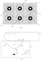
- FIG. 3 schematically illustrates a front view sub-part of the sensor 124 suitable for the first embodiment of the biometric device 12.
- the sensor 124 consists of a matrix of square photoreceptors generally from “1” to “10” ⁇ m on a side.
- Each incidence zone comprises a central disc such as the disc 1244 and a peripheral ring such as the ring 1243, the central disc and the peripheral ring of an incidence zone being concentric.
- Each zone of incidence corresponds to one of the holes of the opaque screen 122 and represents an image of the finger D projected on the sensor 124 seen by said hole when the finger D is placed on the upper face 1200.
- the zone of incidence comprising the central disc 1244 and the peripheral ring 1243 corresponds to the hole 122A.
- each peripheral ring therefore corresponds to the diameter d AP of an image of the finger D projected onto the sensor 124 seen through a hole when the finger D is placed on the upper face 1200.
- the holes of the opaque screen 122 taking the shape of a rectangular matrix of holes, the zones of incidence follow this shape on the sensor 124.
- the holes of the opaque screen 122 are circular, the center of the zone of incidence corresponding to a hole and the center of said hole are confused.
- the part located in a peripheral ring corresponds to an area receiving light rays having passed through the opaque screen 122 by a hole (here the hole 122A) and having an incident angle with the normal to the upper face 1200 between the critical angle ⁇ c and the limit angle ⁇ l .
- the part located inside the central disc corresponds to an area receiving light rays having crossed the opaque screen 122 by a hole (here the hole 122A) and having an incident angle with the normal on the upper face 1200 less than the critical angle ⁇ c .
- Each part of the sensor 124 located inside a central disk therefore corresponds to a part from which it is not desired to recover information.
- the photoreceptors located in each of these parts must therefore be insensitive to light.
- Each part of the sensor 124 located in a peripheral ring therefore corresponds to a part from which it is desired to recover information.
- the photoreceptors located in each of these parts must therefore be sensitive to light. Pixels located outside a peripheral ring receive little, if any, light from the finger if the index of refraction of the finger placed on top face 1200 is lower than the index of refraction of transparent blades 120 and 123.
- the distance L between each hole makes it possible to image at least once each point of the finger D facing the upper face 1200.
- the biometric device 12 having a known geometry, it is possible to determine which photoreceptor(s) s) of the sensor 124 image(s) a point of the finger D. It then becomes possible to reconstitute an image of the imprint of the finger D by known techniques.
- the processing module 11 takes into account the information coming from each photoreceptor having imaged a point to generate a representation of this point in the image of the print. During this generation of a representation, the processing module 11 rebalances the information coming from each photoreceptor with one another by taking into account, for each photoreceptor, information representative of a distance between said photoreceptor and the point which has been imaged. In a particular implementation, when the same point of the finger D is imaged by several photoreceptors of the sensor 124, following the rebalancing, the processing module 11 calculates an average of the information coming from each photoreceptor having imaged this point to generate a representation of that point in a footprint image.
- the sensor 124 is square in shape with a side of “3.9 ” mm comprising square photoreceptors with a side of “4” ⁇ m.
- the transparent blade 123 has a thickness E 123 three to ten times less than the thickness E 120 of the transparent blade 120.
- the transparent blade 123 is glued to the sensor 124 or produced by a series of deposits on the sensor 124.
- Fingerprint imaging standards recommend finger image resolutions greater than 500 or 1000 dots per inch (dpi). With a magnification of ⁇ 1 5 , if you want a finger image sampled at more than 500 dpi (resp. 1000 dpi), you need pixels of less than 10 ⁇ m (resp. less than 5 ⁇ m).
- a critical angle ⁇ c 41.8 degrees
- a limit angle ⁇ l 70 degrees
- a hole diameter of "7" ⁇ m and a thickness of the blade 123 of "60” ⁇ m each central disc has a diameter of approximately “114” ⁇ m and each peripheral ring has an outer diameter of approximately “337” ⁇ m .
- the underside of the opaque screen 122 and the edges of the holes are made absorbent by applying known techniques (application of a layer of black chrome, of an ink layer, texturing of the underside, etc.) in order to minimize reflections between the opaque screen 122 and the sensor 124.
- the LEDs which are represented in the Fig. 2 apart from the blades 120 and 123 for greater clarity, are either integrated on a lower face of the blade 120 ( ie . the face of the blade 120 which is in contact with the opaque screen 122), or integrated on the upper face of the blade 123 (ie the face of the blade 123 comprising the opaque screen 122).
- the LEDs are gallium nitride (GaN) LEDs or OLEDs.
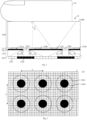
- FIG. 4A schematically illustrates a second embodiment of the biometric device 12 according to the invention.
- the light source is no longer located at the level of the opaque screen 122.
- LEDs are inserted at the level of the sensor 124, ie under the opaque screen 122. At least part of the holes of the The opaque screen 122 has a facing LED.
- the holes of the opaque screen 122 having a facing LED are arranged so that each LED and the LED or LEDs which are the closest neighbors of said LED generate parts directly illuminated by the LEDs at a distance ⁇ less than the distance d p .
- the holes of the opaque screen 122 used to image the finger D are arranged such that the minimum distance L between a hole and the hole or holes which are its closest neighbours, taken from center to center, is greater than the diameter of the image of the finger D seen through a hole when the finger D is placed on the upper face 1200, that is to say L>d AP .
- Each LED can be produced by depositing on the sensor 124.
- each LED is integrated on the surface of the sensor 124.
- each LED is integrated into sensor 124.
- each LED generates a beam of light directed towards the holes having a maximum angle of incidence ⁇ max with respect to a normal to the upper face 1200 making it possible to avoid that after reflection on the opaque screen 122, these LEDs illuminate light-sensitive photoreceptors.
- ⁇ max 23 degrees.
- FIG. 4C schematically illustrates a front view sub-part of an example of sensor 124 adapted to the second embodiment of the biometric device 12.
- the holes of the opaque screen 122 form a rectangular array of holes.
- LEDs have been inserted at positions corresponding to the center of each central disc.
- the LEDs 121A and 121B represented in Fig. 4A
- LEDs 121C, 121D, 121E and 121F There is therefore an LED at each position of the sensor 124 receiving light rays having passed through the opaque screen 122 through a hole and having an incident angle with the normal to the upper face 1200 less than the critical angle ⁇ c .
- the photoreceptors located in a central disk are insensitive to light.
- each LED illuminates a disk in front of it on the finger D when the latter is placed on the upper face 1200.
- the holes have a diameter of "7" ⁇ m
- each LED is circular with a diameter of "10" ⁇ m
- each LED illuminates a disc of approximately "92" ⁇ m .
- an opaque screen comprising regularly distributed holes with a distance of “400” ⁇ m between the centers of the holes, the entire surface of the finger D placed on the upper face 1200 is not illuminated by the LEDs. But, as we have seen above, a finger being a scattering medium, the entire surface of the finger facing the upper face 1200 will reflect light.
- FIG. 4B schematically illustrates an operation of the second embodiment of the biometric device 12.
- FIG. 4B we have represented the projections of 8 zones of incidence on the upper face 1200.
- a point P also represented in the Fig. 4A , appears in the projection of three different peripheral rings. This point P is therefore imaged three times on the sensor 124: a first time at a point P1 following a ray R P 1 , a second time at a point P2 following a ray R P 2 and a third time at a point not represented along a radius R P 3 . Imaging each point of finger D multiple times provides better image quality.
- Each LED of the light source can be lit independently of the other LEDs. For example, it is possible to light a single LED of the light source or all the LEDs of the light source.
- Fig. 6 describes a fraud detection method according to the invention.
- the process described in relation to the Fig. 6 is implemented by the processing module 11 for example, following identification or authentication of a person.
- the biometric device 12 used can be either the biometric device 12 according to the first embodiment described in relation to the Fig. 2 or according to the second embodiment described in relation to the Fig. 4A .
- the processing module 11 causes a first fingerprint image to be acquired by the biometric device 12 with illumination of the finger D by the light source 121 such that the entire surface of the finger D is in contact with the face 1200 returns light.
- the first image obtained is an image in which the pixels representing the peaks have a high light intensity and the pixels representing the valleys have a low light intensity compared to the pixels of the peaks. The contrast between ridges and valleys is therefore important.
- the processing module 11 causes an acquisition of at least one second imprint image with illumination of the body part by the light source 121 using an LED or a plurality of LEDs.
- said LEDs are at least a predefined distance apart. There predefined distance is such that the sub-portion of the finger D returning the light emitted by an LED is disjoint from any other sub-portion of the finger D returning light illuminated by another LED.
- a sub-portion of the finger D returning light is defined as a circular zone of the finger D having a maximum light intensity at its center and whose light intensity decreases radially to a minimum light intensity, l 'minimum light intensity being a predefined percentage (for example 1%) of the maximum light intensity.
- the minimum light intensity can also be defined as a light intensity which is not detectable by the sensor 124. The minimum light intensity therefore defines the limit of the sub-portion of the finger D returning light.
- the processing module causes the lighting of a single predefined LED of the light source 121 to allow acquisition of a single second image.
- only a well-defined and very small zone is illuminated directly on the part of the finger D opposite the face 1200.
- the second image is the most informative image for determining whether the finger D is covered with real skin.
- the processing module 11 obtains information representing a level of light re-emitted by the finger D.
- a profile of light intensity is obtained for each sub-portion of the finger D returning light.
- each sub-part of the finger D returning light is divided into several calculation zones.
- a first central computing area has a disc shape and the other computing areas are concentric rings surrounding the central computing area.
- An average light intensity of the pixels is then calculated for each calculation zone.
- the average light intensity of a zone is calculated from the pixels of said zone representing peaks of the imprint.
- the processing module uses the first image. In the first image, each pixel corresponding to a peak has a high light intensity value compared to a pixel corresponding to a valley.
- the light intensity value of each pixel of the first image is compared with a predefined threshold. Based on this comparison, each pixel of the first image is classified into either a first peak-matching category or a second non-peak-matching category. Pixels whose light intensity value is greater than the predefined threshold are classified in the first category. The pixels whose light intensity value is less than or equal to the predefined threshold are classified in the second category.
- the processing module 11 checks for each pixel of the second image corresponding to said calculation zone, whether the corresponding pixel in the first image has been classified in the pixel class of crest. If so, this pixel is taken into account in the calculation of the average. Otherwise, this pixel is not taken into account in the calculation of the average. From the light intensity average calculated for each calculation zone, the processing module 11 obtains a light intensity curve and a curve of the light intensity gradient as a function of the distance between the calculation zone and the center of the central computing area. The center of the central calculation zone corresponds to the projection of the center of the LED corresponding to this calculation zone on the upper face 1200.
- Each curve obtained constitutes the information representative of the level of light re-emitted by the finger D.
- the processing module 11 compares the information representative of the level of light re-emitted by the finger D with reference information representative of a level of light re-emitted by a real finger placed on the face 1200 to validate that the finger D placed on face 1200 is a real finger.
- the light intensity curve (respectively the gradient curve) as a function of the distance must remain between two limit light intensity curves (respectively two limit light intensity gradient curves) estimated from reference curves.
- the reference curves are here light intensity curves and light intensity gradients which have been established from a large panel real fingers using biometric device 12.
- the light intensity of the pixels of the first image is a value representative of a light coupling efficiency between the sensor 124 and the finger D.
- the processing module 11 uses this information to reconstruct the level of light emitted by the finger D. To do this, the processing module 11 calculates for each calculation zone of the second image, a scalar product between said calculation zone and a spatially corresponding zone in the first image ( ie an identical ring located at the same position in the first image). For each zone, this scalar product is divided, for example, by the squared norm of the first image ( ie by the scalar product of the first image by itself), so as to obtain for each zone a normalized scalar product.
- the processing module 11 obtains a curve of scalar products and a curve of gradients of scalar products as a function of the distance between the calculation zone and the illuminated zone.
- Each curve obtained in this particular implementation constitutes the information representative of the level of light re-emitted by the finger D.
- the processing module 11 uses the curves thus obtained to validate or not the finger D.
- the curve of scalar products (respectively the scalar product gradient curve) as a function of the distance remaining between two limit scalar product curves (respectively two limit scalar product gradient curves) estimated here also from reference scalar product curves.
- the reference curves here are curves of scalar products and gradients of scalar products which have been established from a large panel of real fingers using the biometric device 12.
- an albedo measurement in addition to the calculated normalized scalar product values.
- This albedo measurement can be calculated on the first image in the form of an average or median light intensity value calculated on all the pixels of said image or only on the pixels corresponding to the peaks in the first image.
- the albedo measurement obtained is compared with reference albedo measurements obtained from a large panel of real fingers using the biometric device 12. This albedo measurement is for example used to confirm or invalidate the conclusions taken on the validity of a finger from the scalar product curves and/or the scalar product gradient curves.
- a plurality of LEDs are lit.
- the LEDs of said plurality are chosen so as to obtain several sub-portions of the finger D returning light, each sub-portion being disjoint.
- a pair of curves is obtained comprising a luminous intensity curve (respectively a curve of scalar products) and a curve of luminous intensity gradients (respectively a curve of product gradients scalars).
- Step 68 is applied to each pair of curves.
- the processing module decides that it is in the presence of a fake finger and therefore a fraud.
- a plurality of second images is obtained by successively illuminating the finger D from at least one LED emitting in a different wavelength for each second image.
- a first wavelength is below "600 nm” and a second wavelength is above "600 nm”.
- the processing module 11 implements the steps 66, 67 and 68. If, during at least one application of the step 68, it emerges that the finger D is not a real finger, then the processing module decides that it is in the presence of a false finger and therefore of fraud.
- the processing module uses curves during step 68 limits ( ie curves of limit light intensity, limit light intensity gradients, limit scalar products and limit scalar product gradients) adapted to each wavelength.
- the processing module 11 chooses at least one LED to be lit for the acquisition of each second image according to a predefined criterion.
- the lit LED is the LED closest to a position of a barycenter of the part of the finger D in contact with the face 1200, or the LED closest to a position of the center of curvature, also called core, of the ridges of the part of the finger D in contact with the face 1200 as defined in the document EP3073416 .
- the processing module 11 can locate the finger in the first image and choose each LED to be lit according to the position of the finger thus located.
- two images are compared: an image acquired by the authentication device, called an acquired image, and an image a reference fingerprint stored in a database, called the reference image.
- regions of the imprint of the acquired image are matched with regions of the imprint of the reference image.
- the matched regions are then compared to perform the authentication.
- minutia particular points, called minutia, corresponding to bifurcations and to the ends of visible lines of a print.
- minutia particular points
- Each minutia of the acquired image is compared to a corresponding minutia of the reference image.
- a resemblance score is calculated for each minutia, and an overall resemblance score is calculated for the entire imprint.
- Matched regions and minutiae are representative of the most important information in a fingerprint. There is therefore every interest in looking for possible fraud in the vicinity of these regions or these minutiae.
- the processing module 11 focuses on the minutiae detected in the peaks of the first image to determine whether the finger D is covered with real skin.
- the processing module 11 chooses an LED for illuminating a point of the second image corresponding spatially to a barycenter of minutiae of the first image positively associated with minutiae of the reference image or spatially corresponding to the barycenter of a region of predefined shape of the first image comprising the highest density of minutiae positively associated with minutiae of the reference image.
- the region of predefined shape can for example be a circle.
- Some frauds consist in partially covering a finger with a fake skin. In this case, two zones appear in the imprint image, these two zones being separated by a border. This border may look like a scar. It is then relevant to verify that the light scattering properties in the finger are identical on each side of the boundary. Indeed, different diffusion properties would indicate the presence of a fraud.
- the processing module 11 performs an analysis of this first image in order to detect a possible boundary therein. If a border is detected, the processing module 11 chooses during step 62 a first LED lighting up a first side of the detected border and a second LED lighting up a second side of the detected border.
- step 63 two second images are acquired by successively lighting the first and the second selected LEDs.
- the following stages of the process described in relation to the Fig. 6 are applied independently on every second image.
- the finger is validated if, for each second image, during step 68, the processing module 11 declares the finger valid and if the information representative of the level of light re-emitted by the finger D obtained for the first second image is similar according to a predefined criterion to the information representative of the level of light re-emitted by the finger D obtained for the second second image.
- the method described in relation to the Fig. 6 comprises two intermediate steps 64 and 65 between step 63 and step 67.
- the processing module 11 triggers an acquisition of an additional image without illumination by the light source 121.
- step 65 the additional image is subtracted from the first and from each second image so that in the remainder of the method ( ie steps 67 to 68), these are first and second images resulting from this subtraction which are used instead of the original first and second images.
- This particular implementation makes it possible to improve the performance of the method in the event of illumination by at least one external light source.
- FIG. 7 schematically illustrates an example of hardware architecture of the processing module 11.
- the processing module 11 then comprises, connected by a communication bus 110: a processor or CPU (Central Processing Unit) 111; a random access memory (RAM) 112; a read only memory ROM (Read Only Memory) 113; a storage unit such as a hard disk or a storage medium reader, such as an SD (Secure Digital) card reader 114; at least one communication interface 115 allowing the processing module 11 to communicate with the biometric device 12.
- a communication bus 110 a processor or CPU (Central Processing Unit) 111; a random access memory (RAM) 112; a read only memory ROM (Read Only Memory) 113; a storage unit such as a hard disk or a storage medium reader, such as an SD (Secure Digital) card reader 114; at least one communication interface 115 allowing the processing module 11 to communicate with the biometric device 12.
- a communication bus 110 a processor or CPU (Central Processing Unit) 111
- RAM random access memory
- ROM Read Only Memory
- storage unit such as a hard disk or a storage
- Processor 111 is capable of executing instructions loaded into RAM 112 from ROM 113, external memory (not shown), storage medium (such as an SD card), or a communications network. When the analysis module 11 is powered up, the processor 111 is able to read instructions from the RAM 112 and execute them. These instructions form a computer program causing the implementation, by the processor 111, of the method described in relation to the Fig. 6 .
- the process described in relation to the Fig. 6 can be implemented in software form by executing a set of instructions by a programmable machine, for example a DSP ("Digital Signal Processor” in English), a microcontroller or a GPU (graphics processor, "Graphics Processing Unit” in terminology Anglo-Saxon), or be implemented in hardware form by a dedicated machine or component, for example an FPGA (Field-Programmable Gate Array) or an ASIC (Application-Specific Integrated Circuit).
- a programmable machine for example a DSP ("Digital Signal Processor” in English
- a microcontroller or a GPU graphics processor, "Graphics Processing Unit” in terminology Anglo-Saxon
- FPGA Field-Programmable Gate Array
- ASIC Application-Specific Integrated Circuit
- processing module 11 could just as well have been included in the biometric device 12.
Landscapes
- Engineering & Computer Science (AREA)
- Physics & Mathematics (AREA)
- General Physics & Mathematics (AREA)
- Multimedia (AREA)
- Theoretical Computer Science (AREA)
- Human Computer Interaction (AREA)
- Image Input (AREA)
- Measurement Of The Respiration, Hearing Ability, Form, And Blood Characteristics Of Living Organisms (AREA)
- Pinball Game Machines (AREA)
Claims (13)
- Verfahren zur Betrugserkennung bei einer Benutzung einer Erfassungsvorrichtung eines Abdrucks eines Körperteils, wobei die Vorrichtung ein erstes durchsichtiges Plättchen (120), das eine Oberseite (1200) enthält, auf die ein zu überprüfender Körperteil aufgelegt wird, eine Lichtquelle (121), die eine Vielzahl von LEDs enthält, die ausschließlich in Richtung der Oberseite leuchten, einen lichtundurchlässigen Schirm, der sich unter dem ersten durchsichtigen Plättchen befindet, ein zweites durchsichtiges Plättchen, das sich unter dem undurchlässigen Schirm befindet, und einen Bildsensor (124) enthält, der sich unter dem zweiten durchsichtigen Plättchen (123) befindet, wobei die zwei durchsichtigen Plättchen, der undurchlässige Schirm und der Bildsensor parallel sind und der undurchlässige Schirm (122) ein Netz von Löchern enthält, die dazu bestimmt sind, von der Lichtquelle stammende Lichtstrahlen den Bildsensor (124) erreichen zu lassen, wobei die Lichtstrahlen es dem Bildsensor erlauben, ein Bild des Abdrucks zu erzeugen, wobei jede LED so konfiguriert ist, dass jeder von der LED erzeugte Lichtstrahl einen Winkel bezüglich der Normalen zur Oberseite (1200) hat, der geringer ist als ein kritischer Winkel, dadurch gekennzeichnet, dass das Verfahren enthält:Verwenden der Vorrichtung zum Erfassen (61) eines ersten Abdruckbilds mit einer Beleuchtung des zu überprüfenden Körperteils durch die Lichtquelle, erster Beleuchtungstyp genannt, derart, dass die ganze Fläche des zu überprüfenden Körperteils in Kontakt mit dem durchsichtigen Plättchen Licht zurückwirft;Verwenden der Vorrichtung zum Erfassen (63) mindestens eines zweiten Abdruckbilds mit einer Beleuchtung des zu überprüfenden Körperteils durch die Lichtquelle, zweiter Beleuchtungstyp genannt, derart, dass mindestens eine LED eingeschaltet ist, wenn eine Vielzahl von LEDs eingeschaltet ist, die LEDs mindestens um einen derartigen vordefinierten Abstand beabstandet sind, dass der das von einer LED emittierte Licht zurückwerfende Teilbereich des Fingers D von jedem anderen Licht zurückwerfenden Teilbereich des Fingers D getrennt ist, der von einer anderen LED beleuchtet wird;Erhalt (67) für jedes zweite Abdruckbild einer für ein vom zu überprüfenden Körperteil reemittiertes Lichtniveau repräsentativen Information unter Verwendung des zweiten Abdruckbilds und des ersten Abdruckbilds; undVergleich (68) der Information mit einer für ein von einem auf das durchsichtige Plättchen aufgelegten echten Körperteil reemittiertes Lichtniveau repräsentativen Bezugsinformation, um zu bestätigen, dass der zu überprüfende Körperteil ein echter Körperteil ist, wobei die für ein vom zu überprüfenden Körperteil reemittiertes Lichtniveau repräsentative Information mindestens eine eine vom Körperteil emittierte Lichtstärke darstellende Kurve und mindestens eine Kurve von Gradienten einer vom Körperteil emittierten Lichtstärke abhängig von einem Abstand zu einer Mitte einer direkt von der Lichtquelle (121) beleuchteten Zone, wenn diese den Körperteil gemäß dem zweiten Beleuchtungstyp beleuchtet, wobei jede Kurve erhalten wird, indem nur Lichtstärken von Pixeln berücksichtigt werden, die Graten des Abdrucks des Körperteils entsprechen, wobei die Pixel unter Verwendung des ersten Abdruckbilds identifiziert werden; oder mindestens eine Kurve, die normierte Skalarprodukte darstellt, die zwischen dem ersten und dem zweiten Abdruckbild berechnet werden, und mindestens eine Kurve enthält, die Gradienten von normierten Skalarprodukten darstellt, die zwischen dem ersten und dem zweiten Abdruckbild berechnet werden, abhängig von einem Abstand zu einer Mitte einer direkt von der Lichtquelle (121) beleuchteten Zone, wenn diese den Körperteil gemäß dem zweiten Beleuchtungstyp beleuchtet.
- Verfahren nach Anspruch 1, dadurch gekennzeichnet, dass die für ein vom zu überprüfenden Körperteil reemittiertes Lichtniveau repräsentative Information außerdem ein Albedo-Maß enthält, wobei das Maß ausgehend vom ersten Abdruckbild erhalten wird.
- Verfahren nach Anspruch 1 oder 2, dadurch gekennzeichnet, dass, wenn eine Vielzahl von LEDs gleichzeitig eingeschaltet ist, um ein zweites Abdruckbild zu erhalten, der Erhalt der für ein vom zu überprüfenden Körperteil reemittiertes Lichtniveau repräsentativen Information und der Vergleich der Information mit einer Bezugsinformation für jeden Teilbereich ausgeführt werden, um zu bestätigen, dass der zu überprüfende Körperteil ein echter Körperteil ist.
- Verfahren nach einem der vorhergehenden Ansprüche, dadurch gekennzeichnet, dass, wenn eine Vielzahl zweiter Abdruckbilder erhalten wird, der zweite Beleuchtungstyp für jedes zweite Abdruckbild geändert wird, und der Erhalt der für ein vom zu überprüfenden Körperteil reemittiertes Lichtniveau repräsentativen Information und der Vergleich der Information mit einer Bezugsinformation für jedes zweite Abdruckbild ausgeführt werden, um zu bestätigen, dass der zu überprüfende Körperteil ein echter Körperteil ist.
- Verfahren nach Anspruch 4, dadurch gekennzeichnet, dass die Änderung des zweiten Beleuchtungstyps darin besteht, die vom Beleuchtungssystem emittierte Wellenlänge oder die Position jeder eingeschalteten LED des Beleuchtungssystems für jedes zweite Abdruckbild zu variieren.
- Verfahren nach einem der vorhergehenden Ansprüche, dadurch gekennzeichnet, dass das Verfahren vor der Erfassung jedes zweiten Bilds enthält, mindestens eine für die Erfassung jedes zweiten Bilds einzuschaltende LED gemäß einem unter Verwendung des ersten Bilds vordefinierten ersten Kriterium auszuwählen.
- Verfahren nach Anspruch 6, dadurch gekennzeichnet, dass das Verfahren außerdem enthält, den Finger im ersten Bild zu lokalisieren und jede einzuschaltende LED abhängig von der Position des so lokalisierten Fingers auszuwählen.
- Verfahren nach Anspruch 6 oder 7, dadurch gekennzeichnet, dass, wenn eine zwei Zonen trennende Grenze im ersten Abdruckbild erkannt wird, ein erstes zweites Abdruckbild durch Beleuchten des Körperteils mit einer ersten LED erfasst wird, was einen Teilbereich erzeugt, der Licht von einer ersten Seite der Grenze zurückwirft, und ein zweites zweites Abdruckbild durch Beleuchten des Körperteils mit einer zweiten LED erfasst wird, was einen Teilbereich erzeugt, der Licht von einer zweiten Seite der Grenze zurückwirft, und die für ein vom zu überprüfenden Körperteil reemittiertes Lichtniveau repräsentativen Informationen, die von jedem zweiten Bild stammen, gemäß einem zweiten vordefinierten Kriterium gleich sein müssen, um zu bestätigen, dass der zu überprüfende Körperteil ein echter Körperteil ist.
- Verfahren nach Anspruch 8, dadurch gekennzeichnet, dass, wenn nur eine LED gewählt wird, die gewählte LED die LED ist, die einer Position eines Schwerpunkts des Körperteils in Kontakt mit dem durchsichtigen Plättchen am nächsten ist, oder die einem Krümmungszentrum der Grate des Abdrucks des Körperteils in Kontakt mit dem durchsichtigen Plättchen am nächsten ist, oder die einem Schwerpunkt von in den Graten des Abdrucks erkannten Minuzien am nächsten ist.
- Verfahren nach einem der vorhergehenden Ansprüche, dadurch gekennzeichnet, dass das Verfahren außerdem enthält:Erfassen eines zusätzlichen Abdruckbilds ohne Beleuchtung durch die Lichtquelle;Ausführen einer Subtraktion des zusätzlichen Abdruckbilds vom ersten und von jedem zweiten Bild, so dass das erste und jedes zweite Abdruckbild, die beim Erhalt der für ein vom zu überprüfenden Körperteil reemittiertes Lichtniveau repräsentativen Information und beim Vergleich der Information mit einer Bezugsinformation verwendet werden, Bilder sind, die von dieser Subtraktion stammen.
- Vorrichtung, die Einrichtungen zur Durchführung des Verfahrens nach einem der Ansprüche 1 bis 10 enthält.
- Gerät, das eine Vorrichtung nach Anspruch 11 enthält.
- Computerprogramm, dadurch gekennzeichnet, dass es Anweisungen enthält, um das Verfahren nach einem der Ansprüche 1 bis 10 durch eine Vorrichtung durchzuführen, wenn das Programm von einer Recheneinheit der Vorrichtung ausgeführt wird.
Applications Claiming Priority (1)
| Application Number | Priority Date | Filing Date | Title |
|---|---|---|---|
| FR1753180A FR3065306B1 (fr) | 2017-04-12 | 2017-04-12 | Procede de detection de fraude |
Publications (2)
| Publication Number | Publication Date |
|---|---|
| EP3388976A1 EP3388976A1 (de) | 2018-10-17 |
| EP3388976B1 true EP3388976B1 (de) | 2023-03-01 |
Family
ID=59811397
Family Applications (1)
| Application Number | Title | Priority Date | Filing Date |
|---|---|---|---|
| EP18166590.2A Active EP3388976B1 (de) | 2017-04-12 | 2018-04-10 | Betrugserkennungsverfahren |
Country Status (4)
| Country | Link |
|---|---|
| US (1) | US10380408B2 (de) |
| EP (1) | EP3388976B1 (de) |
| CN (1) | CN108694378A (de) |
| FR (1) | FR3065306B1 (de) |
Families Citing this family (4)
| Publication number | Priority date | Publication date | Assignee | Title |
|---|---|---|---|---|
| US10616453B2 (en) * | 2017-01-11 | 2020-04-07 | Nokia Technologies Oy | Audio and visual system including a mask functioning for a camera module and an audio transducer module |
| FR3064112B1 (fr) * | 2017-03-16 | 2021-06-18 | Commissariat Energie Atomique | Dispositif imageur optique |
| CN109643379B (zh) * | 2018-11-19 | 2023-06-23 | 深圳市汇顶科技股份有限公司 | 指纹识别方法、装置和电子设备 |
| CN111095275B (zh) * | 2019-08-29 | 2023-09-05 | 深圳市汇顶科技股份有限公司 | 指纹识别的装置、方法和电子设备 |
Family Cites Families (14)
| Publication number | Priority date | Publication date | Assignee | Title |
|---|---|---|---|---|
| FR2757974B1 (fr) | 1996-12-27 | 1999-02-12 | Sagem | Capteur optique d'empreinte digitale |
| FR2907940B1 (fr) * | 2006-10-25 | 2009-05-01 | Sagem Defense Securite | Procede de validation de capture d'empreinte corporelle, notamment d'une empreinte digitale |
| CN102713967B (zh) * | 2009-10-26 | 2016-04-20 | 日本电气株式会社 | 伪指确定装置及伪指确定方法 |
| FR2981769B1 (fr) * | 2011-10-25 | 2013-12-27 | Morpho | Dispositif anti-fraude |
| JP6075069B2 (ja) * | 2013-01-15 | 2017-02-08 | 富士通株式会社 | 生体情報撮像装置及び生体認証装置ならびに生体情報撮像装置の製造方法 |
| NL2012891B1 (en) * | 2013-06-05 | 2016-06-21 | Apple Inc | Biometric sensor chip having distributed sensor and control circuitry. |
| FR3015728B1 (fr) | 2013-12-19 | 2019-04-19 | Morpho | Procede de validation destine a valider qu'un element est recouvert d'une vraie peau |
| FR3030834B1 (fr) * | 2014-12-22 | 2017-02-10 | Commissariat Energie Atomique | Procede et systeme d'acquisition et d'analyse d'empreintes avec detection de fraude |
| CN105989327A (zh) * | 2015-02-02 | 2016-10-05 | 神盾股份有限公司 | 指纹感测装置及其感测方法 |
| KR102277453B1 (ko) * | 2015-02-05 | 2021-07-14 | 삼성전자주식회사 | 터치 센서를 구비한 전자 장치 및 그 구동 방법 |
| FR3034224B1 (fr) | 2015-03-23 | 2018-03-23 | Morpho | Dispositif de verification de la veracite d'une empreinte digitale |
| FR3040225B1 (fr) * | 2015-08-18 | 2017-07-28 | Morpho | Capteur biometrique avec au moins deux sources lumineuses a angles apparent differents |
| FR3045884B1 (fr) * | 2015-12-18 | 2017-12-08 | Morpho | Procede de detection de fraude pour authentifier un doigt |
| US10089514B1 (en) * | 2017-03-31 | 2018-10-02 | Synaptics Incorporated | Adaptive reference for differential capacitive measurements |
-
2017
- 2017-04-12 FR FR1753180A patent/FR3065306B1/fr not_active Expired - Fee Related
-
2018
- 2018-04-09 US US15/948,371 patent/US10380408B2/en active Active
- 2018-04-10 EP EP18166590.2A patent/EP3388976B1/de active Active
- 2018-04-12 CN CN201810325629.1A patent/CN108694378A/zh active Pending
Also Published As
| Publication number | Publication date |
|---|---|
| FR3065306A1 (fr) | 2018-10-19 |
| US10380408B2 (en) | 2019-08-13 |
| CN108694378A (zh) | 2018-10-23 |
| US20180300528A1 (en) | 2018-10-18 |
| FR3065306B1 (fr) | 2019-04-05 |
| EP3388976A1 (de) | 2018-10-17 |
Similar Documents
| Publication | Publication Date | Title |
|---|---|---|
| EP3388975B1 (de) | Sensorvorrichtung zur aufnahme eines abdrucks eines körperteils | |
| EP3312771B1 (de) | Vorrichtung zum schnellen erfassen von fingerabdrücken | |
| US10282582B2 (en) | Finger biometric sensor for generating three dimensional fingerprint ridge data and related methods | |
| EP3388976B1 (de) | Betrugserkennungsverfahren | |
| EP0900427A1 (de) | Anlage und verfahren zur relieffingerabdruckerfassung | |
| EP2902943A1 (de) | Validierungsverfahren für die Verwendung eines echten Fingers als Auflagefläche für einen digitalen Fingerabdruck | |
| EP3044729B1 (de) | Validierungsverfahren zur validierung der abdeckung eines elements durch echte haut | |
| WO2005006241A2 (fr) | Dispositif d'imagerie optique, destine notamment a la reconnaissance d'empreintes digitales. | |
| CA3000153A1 (fr) | Procede d'analyse d'un document structure susceptible d'etre deforme | |
| WO2016102854A1 (fr) | Procédé et système d'acquisition et d'analyse d'empreintes avec détection de fraude | |
| FR3053500B1 (fr) | Procede de detection de fraude d'un systeme de reconnaissance d'iris | |
| EP3726423B1 (de) | Vorrichtung und verfahren zur biometrischen erfassung und verarbeitung | |
| FR3078793A1 (fr) | Procede d'authentification d'un visage base sur la reflectance | |
| EP3401837A1 (de) | Vorrichtung zum abnehmen von fingerabdrücken | |
| EP3614305A1 (de) | Authentifizierung durch optischen index | |
| EP3471016B1 (de) | Präsenzerkennungsverfahren eines körperteils, der einen fingerabdruck auf einem fingerabdrucksensor erzeugen kann | |
| EP3073441B1 (de) | Verfahren zur korrektur eines bildes mindestens eines objekts, das vor einem bildanzeigegerät in der ferne dargestellt und von einem beleuchtungssystem beleuchtet wird, und bildaufnahmesystem für die umsetzung dieses verfahrens | |
| FR3021783A1 (fr) | Procede de validation de l'authenticite d'un element du corps humain | |
| EP3036687A2 (de) | Entscheidungsvorrichtung zur entscheidung über die echtheit eines auges | |
| WO2017029455A1 (fr) | Capteur biometrique avec au moins deux sources lumineuses a tailles apparentes differentes | |
| EP3206160A1 (de) | Verfahren zur biometrischen aufbereitung von bildern | |
| EP4105897B1 (de) | Vorrichtung zur biometrischen erfassung | |
| FR3024252A1 (fr) | Acquisition numerique d'un trace manuscrit | |
| KR20190121126A (ko) | 사기 행위 탐지 방법 | |
| FR3059449A1 (fr) | Procede de detection de fraude d'un systeme de reconnaissance d'iris |
Legal Events
| Date | Code | Title | Description |
|---|---|---|---|
| PUAI | Public reference made under article 153(3) epc to a published international application that has entered the european phase |
Free format text: ORIGINAL CODE: 0009012 |
|
| STAA | Information on the status of an ep patent application or granted ep patent |
Free format text: STATUS: REQUEST FOR EXAMINATION WAS MADE |
|
| 17P | Request for examination filed |
Effective date: 20180410 |
|
| AK | Designated contracting states |
Kind code of ref document: A1 Designated state(s): AL AT BE BG CH CY CZ DE DK EE ES FI FR GB GR HR HU IE IS IT LI LT LU LV MC MK MT NL NO PL PT RO RS SE SI SK SM TR |
|
| AX | Request for extension of the european patent |
Extension state: BA ME |
|
| RAP1 | Party data changed (applicant data changed or rights of an application transferred) |
Owner name: IDEMIA IDENTITY & SECURITY FRANCE |
|
| STAA | Information on the status of an ep patent application or granted ep patent |
Free format text: STATUS: EXAMINATION IS IN PROGRESS |
|
| 17Q | First examination report despatched |
Effective date: 20200903 |
|
| REG | Reference to a national code |
Ref country code: DE Ipc: G06V0040120000 Ref country code: DE Ref legal event code: R079 Ref document number: 602018046590 Country of ref document: DE Free format text: PREVIOUS MAIN CLASS: G06K0009000000 Ipc: G06V0040120000 |
|
| GRAP | Despatch of communication of intention to grant a patent |
Free format text: ORIGINAL CODE: EPIDOSNIGR1 |
|
| STAA | Information on the status of an ep patent application or granted ep patent |
Free format text: STATUS: GRANT OF PATENT IS INTENDED |
|
| RIC1 | Information provided on ipc code assigned before grant |
Ipc: G06V 40/12 20220101AFI20220909BHEP |
|
| INTG | Intention to grant announced |
Effective date: 20221005 |
|
| GRAS | Grant fee paid |
Free format text: ORIGINAL CODE: EPIDOSNIGR3 |
|
| GRAA | (expected) grant |
Free format text: ORIGINAL CODE: 0009210 |
|
| STAA | Information on the status of an ep patent application or granted ep patent |
Free format text: STATUS: THE PATENT HAS BEEN GRANTED |
|
| AK | Designated contracting states |
Kind code of ref document: B1 Designated state(s): AL AT BE BG CH CY CZ DE DK EE ES FI FR GB GR HR HU IE IS IT LI LT LU LV MC MK MT NL NO PL PT RO RS SE SI SK SM TR |
|
| REG | Reference to a national code |
Ref country code: GB Ref legal event code: FG4D Free format text: NOT ENGLISH |
|
| REG | Reference to a national code |
Ref country code: CH Ref legal event code: EP Ref country code: AT Ref legal event code: REF Ref document number: 1551535 Country of ref document: AT Kind code of ref document: T Effective date: 20230315 |
|
| REG | Reference to a national code |
Ref country code: DE Ref legal event code: R096 Ref document number: 602018046590 Country of ref document: DE |
|
| REG | Reference to a national code |
Ref country code: IE Ref legal event code: FG4D Free format text: LANGUAGE OF EP DOCUMENT: FRENCH |
|
| P01 | Opt-out of the competence of the unified patent court (upc) registered |
Effective date: 20230428 |
|
| REG | Reference to a national code |
Ref country code: LT Ref legal event code: MG9D |
|
| REG | Reference to a national code |
Ref country code: NL Ref legal event code: MP Effective date: 20230301 |
|
| PG25 | Lapsed in a contracting state [announced via postgrant information from national office to epo] |
Ref country code: RS Free format text: LAPSE BECAUSE OF FAILURE TO SUBMIT A TRANSLATION OF THE DESCRIPTION OR TO PAY THE FEE WITHIN THE PRESCRIBED TIME-LIMIT Effective date: 20230301 Ref country code: NO Free format text: LAPSE BECAUSE OF FAILURE TO SUBMIT A TRANSLATION OF THE DESCRIPTION OR TO PAY THE FEE WITHIN THE PRESCRIBED TIME-LIMIT Effective date: 20230601 Ref country code: LV Free format text: LAPSE BECAUSE OF FAILURE TO SUBMIT A TRANSLATION OF THE DESCRIPTION OR TO PAY THE FEE WITHIN THE PRESCRIBED TIME-LIMIT Effective date: 20230301 Ref country code: LT Free format text: LAPSE BECAUSE OF FAILURE TO SUBMIT A TRANSLATION OF THE DESCRIPTION OR TO PAY THE FEE WITHIN THE PRESCRIBED TIME-LIMIT Effective date: 20230301 Ref country code: HR Free format text: LAPSE BECAUSE OF FAILURE TO SUBMIT A TRANSLATION OF THE DESCRIPTION OR TO PAY THE FEE WITHIN THE PRESCRIBED TIME-LIMIT Effective date: 20230301 Ref country code: ES Free format text: LAPSE BECAUSE OF FAILURE TO SUBMIT A TRANSLATION OF THE DESCRIPTION OR TO PAY THE FEE WITHIN THE PRESCRIBED TIME-LIMIT Effective date: 20230301 |
|
| PGFP | Annual fee paid to national office [announced via postgrant information from national office to epo] |
Ref country code: FR Payment date: 20230420 Year of fee payment: 6 Ref country code: DE Payment date: 20230419 Year of fee payment: 6 |
|
| REG | Reference to a national code |
Ref country code: AT Ref legal event code: MK05 Ref document number: 1551535 Country of ref document: AT Kind code of ref document: T Effective date: 20230301 |
|
| PG25 | Lapsed in a contracting state [announced via postgrant information from national office to epo] |
Ref country code: SE Free format text: LAPSE BECAUSE OF FAILURE TO SUBMIT A TRANSLATION OF THE DESCRIPTION OR TO PAY THE FEE WITHIN THE PRESCRIBED TIME-LIMIT Effective date: 20230301 Ref country code: PL Free format text: LAPSE BECAUSE OF FAILURE TO SUBMIT A TRANSLATION OF THE DESCRIPTION OR TO PAY THE FEE WITHIN THE PRESCRIBED TIME-LIMIT Effective date: 20230301 Ref country code: NL Free format text: LAPSE BECAUSE OF FAILURE TO SUBMIT A TRANSLATION OF THE DESCRIPTION OR TO PAY THE FEE WITHIN THE PRESCRIBED TIME-LIMIT Effective date: 20230301 Ref country code: GR Free format text: LAPSE BECAUSE OF FAILURE TO SUBMIT A TRANSLATION OF THE DESCRIPTION OR TO PAY THE FEE WITHIN THE PRESCRIBED TIME-LIMIT Effective date: 20230602 Ref country code: FI Free format text: LAPSE BECAUSE OF FAILURE TO SUBMIT A TRANSLATION OF THE DESCRIPTION OR TO PAY THE FEE WITHIN THE PRESCRIBED TIME-LIMIT Effective date: 20230301 |
|
| PG25 | Lapsed in a contracting state [announced via postgrant information from national office to epo] |
Ref country code: SM Free format text: LAPSE BECAUSE OF FAILURE TO SUBMIT A TRANSLATION OF THE DESCRIPTION OR TO PAY THE FEE WITHIN THE PRESCRIBED TIME-LIMIT Effective date: 20230301 Ref country code: RO Free format text: LAPSE BECAUSE OF FAILURE TO SUBMIT A TRANSLATION OF THE DESCRIPTION OR TO PAY THE FEE WITHIN THE PRESCRIBED TIME-LIMIT Effective date: 20230301 Ref country code: PT Free format text: LAPSE BECAUSE OF FAILURE TO SUBMIT A TRANSLATION OF THE DESCRIPTION OR TO PAY THE FEE WITHIN THE PRESCRIBED TIME-LIMIT Effective date: 20230703 Ref country code: EE Free format text: LAPSE BECAUSE OF FAILURE TO SUBMIT A TRANSLATION OF THE DESCRIPTION OR TO PAY THE FEE WITHIN THE PRESCRIBED TIME-LIMIT Effective date: 20230301 Ref country code: CZ Free format text: LAPSE BECAUSE OF FAILURE TO SUBMIT A TRANSLATION OF THE DESCRIPTION OR TO PAY THE FEE WITHIN THE PRESCRIBED TIME-LIMIT Effective date: 20230301 Ref country code: AT Free format text: LAPSE BECAUSE OF FAILURE TO SUBMIT A TRANSLATION OF THE DESCRIPTION OR TO PAY THE FEE WITHIN THE PRESCRIBED TIME-LIMIT Effective date: 20230301 |
|
| PG25 | Lapsed in a contracting state [announced via postgrant information from national office to epo] |
Ref country code: SK Free format text: LAPSE BECAUSE OF FAILURE TO SUBMIT A TRANSLATION OF THE DESCRIPTION OR TO PAY THE FEE WITHIN THE PRESCRIBED TIME-LIMIT Effective date: 20230301 Ref country code: IS Free format text: LAPSE BECAUSE OF FAILURE TO SUBMIT A TRANSLATION OF THE DESCRIPTION OR TO PAY THE FEE WITHIN THE PRESCRIBED TIME-LIMIT Effective date: 20230701 |
|
| REG | Reference to a national code |
Ref country code: CH Ref legal event code: PL |
|
| REG | Reference to a national code |
Ref country code: DE Ref legal event code: R097 Ref document number: 602018046590 Country of ref document: DE |
|
| PG25 | Lapsed in a contracting state [announced via postgrant information from national office to epo] |
Ref country code: LU Free format text: LAPSE BECAUSE OF NON-PAYMENT OF DUE FEES Effective date: 20230410 |
|
| PLBE | No opposition filed within time limit |
Free format text: ORIGINAL CODE: 0009261 |
|
| STAA | Information on the status of an ep patent application or granted ep patent |
Free format text: STATUS: NO OPPOSITION FILED WITHIN TIME LIMIT |
|
| REG | Reference to a national code |
Ref country code: BE Ref legal event code: MM Effective date: 20230430 |
|
| PG25 | Lapsed in a contracting state [announced via postgrant information from national office to epo] |
Ref country code: MC Free format text: LAPSE BECAUSE OF FAILURE TO SUBMIT A TRANSLATION OF THE DESCRIPTION OR TO PAY THE FEE WITHIN THE PRESCRIBED TIME-LIMIT Effective date: 20230301 |
|
| PG25 | Lapsed in a contracting state [announced via postgrant information from national office to epo] |
Ref country code: SI Free format text: LAPSE BECAUSE OF FAILURE TO SUBMIT A TRANSLATION OF THE DESCRIPTION OR TO PAY THE FEE WITHIN THE PRESCRIBED TIME-LIMIT Effective date: 20230301 Ref country code: MC Free format text: LAPSE BECAUSE OF FAILURE TO SUBMIT A TRANSLATION OF THE DESCRIPTION OR TO PAY THE FEE WITHIN THE PRESCRIBED TIME-LIMIT Effective date: 20230301 Ref country code: LI Free format text: LAPSE BECAUSE OF NON-PAYMENT OF DUE FEES Effective date: 20230430 Ref country code: DK Free format text: LAPSE BECAUSE OF FAILURE TO SUBMIT A TRANSLATION OF THE DESCRIPTION OR TO PAY THE FEE WITHIN THE PRESCRIBED TIME-LIMIT Effective date: 20230301 Ref country code: CH Free format text: LAPSE BECAUSE OF NON-PAYMENT OF DUE FEES Effective date: 20230430 |
|
| 26N | No opposition filed |
Effective date: 20231204 |
|
| REG | Reference to a national code |
Ref country code: IE Ref legal event code: MM4A |
|
| GBPC | Gb: european patent ceased through non-payment of renewal fee |
Effective date: 20230601 |
|
| PG25 | Lapsed in a contracting state [announced via postgrant information from national office to epo] |
Ref country code: BE Free format text: LAPSE BECAUSE OF NON-PAYMENT OF DUE FEES Effective date: 20230430 |
|
| PG25 | Lapsed in a contracting state [announced via postgrant information from national office to epo] |
Ref country code: IE Free format text: LAPSE BECAUSE OF NON-PAYMENT OF DUE FEES Effective date: 20230410 |
|
| PG25 | Lapsed in a contracting state [announced via postgrant information from national office to epo] |
Ref country code: IE Free format text: LAPSE BECAUSE OF NON-PAYMENT OF DUE FEES Effective date: 20230410 Ref country code: GB Free format text: LAPSE BECAUSE OF NON-PAYMENT OF DUE FEES Effective date: 20230601 |
|
| PG25 | Lapsed in a contracting state [announced via postgrant information from national office to epo] |
Ref country code: IT Free format text: LAPSE BECAUSE OF FAILURE TO SUBMIT A TRANSLATION OF THE DESCRIPTION OR TO PAY THE FEE WITHIN THE PRESCRIBED TIME-LIMIT Effective date: 20230301 |
|
| REG | Reference to a national code |
Ref country code: DE Ref legal event code: R119 Ref document number: 602018046590 Country of ref document: DE |
|
| PG25 | Lapsed in a contracting state [announced via postgrant information from national office to epo] |
Ref country code: BG Free format text: LAPSE BECAUSE OF FAILURE TO SUBMIT A TRANSLATION OF THE DESCRIPTION OR TO PAY THE FEE WITHIN THE PRESCRIBED TIME-LIMIT Effective date: 20230301 |
|
| PG25 | Lapsed in a contracting state [announced via postgrant information from national office to epo] |
Ref country code: BG Free format text: LAPSE BECAUSE OF FAILURE TO SUBMIT A TRANSLATION OF THE DESCRIPTION OR TO PAY THE FEE WITHIN THE PRESCRIBED TIME-LIMIT Effective date: 20230301 |
|
| PG25 | Lapsed in a contracting state [announced via postgrant information from national office to epo] |
Ref country code: DE Free format text: LAPSE BECAUSE OF NON-PAYMENT OF DUE FEES Effective date: 20241105 |
|
| PG25 | Lapsed in a contracting state [announced via postgrant information from national office to epo] |
Ref country code: FR Free format text: LAPSE BECAUSE OF NON-PAYMENT OF DUE FEES Effective date: 20240430 |
|
| PG25 | Lapsed in a contracting state [announced via postgrant information from national office to epo] |
Ref country code: FR Free format text: LAPSE BECAUSE OF NON-PAYMENT OF DUE FEES Effective date: 20240430 Ref country code: DE Free format text: LAPSE BECAUSE OF NON-PAYMENT OF DUE FEES Effective date: 20241105 |
|
| PG25 | Lapsed in a contracting state [announced via postgrant information from national office to epo] |
Ref country code: CY Free format text: LAPSE BECAUSE OF FAILURE TO SUBMIT A TRANSLATION OF THE DESCRIPTION OR TO PAY THE FEE WITHIN THE PRESCRIBED TIME-LIMIT; INVALID AB INITIO Effective date: 20180410 |
|
| PG25 | Lapsed in a contracting state [announced via postgrant information from national office to epo] |
Ref country code: HU Free format text: LAPSE BECAUSE OF FAILURE TO SUBMIT A TRANSLATION OF THE DESCRIPTION OR TO PAY THE FEE WITHIN THE PRESCRIBED TIME-LIMIT; INVALID AB INITIO Effective date: 20180410 |
|
| PG25 | Lapsed in a contracting state [announced via postgrant information from national office to epo] |
Ref country code: TR Free format text: LAPSE BECAUSE OF FAILURE TO SUBMIT A TRANSLATION OF THE DESCRIPTION OR TO PAY THE FEE WITHIN THE PRESCRIBED TIME-LIMIT Effective date: 20230301 |