EP3389055A1 - Équipement à rayons x destiné à la production de rayons x à haute énergie - Google Patents
Équipement à rayons x destiné à la production de rayons x à haute énergie Download PDFInfo
- Publication number
- EP3389055A1 EP3389055A1 EP17165888.3A EP17165888A EP3389055A1 EP 3389055 A1 EP3389055 A1 EP 3389055A1 EP 17165888 A EP17165888 A EP 17165888A EP 3389055 A1 EP3389055 A1 EP 3389055A1
- Authority
- EP
- European Patent Office
- Prior art keywords
- electron beam
- target
- ray
- diaphragm
- ray device
- Prior art date
- Legal status (The legal status is an assumption and is not a legal conclusion. Google has not performed a legal analysis and makes no representation as to the accuracy of the status listed.)
- Granted
Links
Images

Classifications
-
- H—ELECTRICITY
- H05—ELECTRIC TECHNIQUES NOT OTHERWISE PROVIDED FOR
- H05G—X-RAY TECHNIQUE
- H05G1/00—X-ray apparatus involving X-ray tubes; Circuits therefor
- H05G1/08—Electrical details
- H05G1/26—Measuring, controlling or protecting
- H05G1/30—Controlling
- H05G1/52—Target size or shape; Direction of electron beam, e.g. in tubes with one anode and more than one cathode
-
- H—ELECTRICITY
- H01—ELECTRIC ELEMENTS
- H01J—ELECTRIC DISCHARGE TUBES OR DISCHARGE LAMPS
- H01J35/00—X-ray tubes
- H01J35/02—Details
- H01J35/16—Vessels; Containers; Shields associated therewith
-
- G—PHYSICS
- G21—NUCLEAR PHYSICS; NUCLEAR ENGINEERING
- G21K—HANDLING OF PARTICLES OR IONISING RADIATION NOT OTHERWISE PROVIDED FOR; IRRADIATION DEVICES; GAMMA RAY OR X-RAY MICROSCOPES
- G21K1/00—Arrangements for handling particles or ionising radiation, e.g. focusing or moderating
- G21K1/02—Arrangements for handling particles or ionising radiation, e.g. focusing or moderating using diaphragms, collimators
-
- H—ELECTRICITY
- H01—ELECTRIC ELEMENTS
- H01J—ELECTRIC DISCHARGE TUBES OR DISCHARGE LAMPS
- H01J35/00—X-ray tubes
-
- H—ELECTRICITY
- H05—ELECTRIC TECHNIQUES NOT OTHERWISE PROVIDED FOR
- H05H—PLASMA TECHNIQUE; PRODUCTION OF ACCELERATED ELECTRICALLY-CHARGED PARTICLES OR OF NEUTRONS; PRODUCTION OR ACCELERATION OF NEUTRAL MOLECULAR OR ATOMIC BEAMS
- H05H6/00—Targets for producing nuclear reactions
-
- G—PHYSICS
- G21—NUCLEAR PHYSICS; NUCLEAR ENGINEERING
- G21K—HANDLING OF PARTICLES OR IONISING RADIATION NOT OTHERWISE PROVIDED FOR; IRRADIATION DEVICES; GAMMA RAY OR X-RAY MICROSCOPES
- G21K1/00—Arrangements for handling particles or ionising radiation, e.g. focusing or moderating
- G21K1/10—Scattering devices; Absorbing devices; Ionising radiation filters
-
- H—ELECTRICITY
- H01—ELECTRIC ELEMENTS
- H01J—ELECTRIC DISCHARGE TUBES OR DISCHARGE LAMPS
- H01J2235/00—X-ray tubes
- H01J2235/08—Targets (anodes) and X-ray converters
-
- H—ELECTRICITY
- H01—ELECTRIC ELEMENTS
- H01J—ELECTRIC DISCHARGE TUBES OR DISCHARGE LAMPS
- H01J2235/00—X-ray tubes
- H01J2235/12—Cooling
- H01J2235/1225—Cooling characterised by method
- H01J2235/1262—Circulating fluids
-
- H—ELECTRICITY
- H05—ELECTRIC TECHNIQUES NOT OTHERWISE PROVIDED FOR
- H05H—PLASMA TECHNIQUE; PRODUCTION OF ACCELERATED ELECTRICALLY-CHARGED PARTICLES OR OF NEUTRONS; PRODUCTION OR ACCELERATION OF NEUTRAL MOLECULAR OR ATOMIC BEAMS
- H05H9/00—Linear accelerators
- H05H9/04—Standing-wave linear accelerators
- H05H9/048—Lepton LINACS
Definitions
- the invention relates to an X-ray device for generating high-energy X-ray radiation, comprising a linear accelerator and a target.
- the linear accelerator is designed to generate X-radiation to produce an electron beam directed at the target, whose kinetic energy per electron is at least 1 MeV.
- X-ray devices typically include an electron beam source that provides an accelerated electron beam for impinging a target (also: target material). When the electrons strike the target, X-rays are generated in the area of the so-called focal spot.
- the electron beam source is usually formed by a cathode, wherein the exiting electrodes are accelerated by an applied acceleration field strength in the direction of an anode, which forms the target in such embodiments.
- a linear accelerator as the electron beam source, which provides an electron beam directed at the target.
- the electron beam passes through an aperture channel delimiting it laterally, which is introduced in a diaphragm body.
- an aperture channel delimiting it laterally, which is introduced in a diaphragm body.
- the area around the aperture channel must be made as solid as possible, if appropriate, water cooling is additionally provided.
- an object of the present invention is to provide an X-ray device for generating high-energy X-radiation, in which the extent of the focal spot on the target can be minimized.
- An X-ray device for generating high-energy X-ray radiation comprises a linear accelerator and a target.
- the target typically consists of a target material which serves to generate X-radiation by decelerating the accelerated electrons.
- the area of the target in which this conversion takes place is called the focal spot.
- the linear accelerator is further adapted and adapted to generate an electron beam directed at the target, the kinetic energy of which per electron is at least 1 MeV.
- a diaphragm is arranged in the beam path of the electron beam between the linear accelerator and the target, which diaphragm has an edge region surrounding an aperture, whose material thickness in the propagation direction of the electron beam is less than 10% of the mean range of electrons of the kinetic energy generated in the material of the edge region.
- the invention chooses to limit the focal spot in this energetic region by the approach of providing a stop which is not designed to absorb the electrons of the generated energy range to a considerable extent, but rather that the interaction is essentially limited to inelastic or elastic scattering processes shall be.
- the diaphragm has a material thickness which is only a fraction of the average range of electrons of the kinetic energy generated in the material of the edge region.
- the peripheral electrons which penetrate the edge region undergo a deflection and are scattered.
- the subsequently divergently propagating electrons then generally no longer strike the target material forming the target.
- the focal spot generating region of the electron beam is thus limited to substantially the area of the aperture.
- the energy transfer to the diaphragm is minimal, since it is based essentially only on inelastic scattering effects. This requires inter alia a lower heat input to the panel, which therefore does not necessarily have to be additionally cooled.
- the edge region of the diaphragm forms a scattering body (also: diffuser) for the electrons passing through the energy range predetermined by the applied acceleration voltage.
- the case deflected randomly Electrons can be absorbed in other regions of the X-ray device and are therefore no longer visible in the useful radiation field of the X-radiation generated.
- the limitation of the extent of the focal spot on the target requires inter alia an improved image quality in imaging processes.
- the captured images have a lower blur or smaller penumbra, as the extent of the focal spot approaches an ideal point source.
- Possible fields of application relate, for example, to radioscopy, in particular the non-destructive testing of workpieces, components or other objects, the checking of goods in transit, in particular as part of a freight inspection in which, for example, trucks or freight containers for trains or container ships are illuminated to make their content visible or Applications in the field of medicine, in particular in the field of radiotherapy.
- a more precise dose distribution can be realized in radiation therapy, in particular in the case of intensity-modulated radiation therapy, since the partial shadows of the collimator delimiting the photon radiation field are smaller.
- the X-ray devices can be optimized in terms of their weight, since downstream collimators for collimating the generated X-ray radiation can be omitted or at least limited.
- the diaphragm consists in a simple embodiment of a thin sheet, in particular steel or other transition metal or alloy.
- Another particularly preferred non-metallic material for the panel is graphite, for example.
- the material and the material thickness of the diaphragm, at least in the edge region surrounding the diaphragm opening, are based on the kinetic energy of the electrons generated during the intended use of the X-ray device is tuned.
- the material thickness is typically in the range of one or more millimeters if it is made of a light material such as graphite. Apertures made of a heavier material, in particular metal, have lower material thicknesses, for example in the submillimeter range, in particular in the range of approximately 1/10 mm.
- At least the electron-scattering edge region of the diaphragm is formed by one or more foils.
- Such embodiments are to be regarded as cost-effective implementations of a scatterer of small thickness, in which it is ensured that the interaction with the electrons of the kinetic energy generated is essentially limited to scattering processes. If the region of the diaphragm which is the cause of the scattering of the electrons is formed by such a film material, then the heat input is minimal.
- the apertures formed in this way therefore do not necessarily have to be actively cooled during the operation of the X-ray device.
- the film is preferably made of a metal.
- the diaphragm or at least the scattering edge region of the diaphragm consists of titanium.
- the diaphragm or at least the edge region surrounding the diaphragm opening consists of stainless steel, tungsten or copper or of another transition metal or transition metal alloy.
- the diaphragm in particular the diaphragm described above consisting of at least one metallic foil, can be cooled in one possible embodiment by means of a cooling device, in particular by means of a water cooling device. This ensures that even the relatively low heat transfer transmitted by inelastic scattering processes can be dissipated reliably.
- a collimator is arranged in the beam path of the X-rays generated by the application of the target. This serves to limit the useful radiation field of the generated X-radiation. If the location of the X-ray generation (focal spot) is small, the half-shadows at the boundaries of the useful-beam field are also small.
- a vacuum housing surrounding at least the linear accelerator, the diaphragm and the target, or a vacuum envelope surrounding these components is provided at least in regions with a shield which is suitable for absorbing x-radiation caused by scattered electrons which impinge on the vacuum housing and be slowed down.
- the resulting X-ray radiation can be spectrally influenced by the choice of the wall material and is preferably shielded locally by a shield arranged outside the vacuum housing.
- the shield is provided inside the vacuum housing. Since the vacuum housing of the X-ray device is evacuated, the shield provided in the interior of the vacuum housing preferably consists of a material with a high vapor pressure, particularly preferably the shield comprises elements with a low atomic number.
- This shield consists for example wholly or partly of lead. Since the scattered electrons are not absorbed by the material of the diaphragm, they spread divergently to the propagation direction of the electron beam and impinge on the shielded vacuum housing from which they are absorbed. Since the absorption of the scattered at the aperture electrons in a highly localized area, but in large areas of the vacuum housing, also here can generally be dispensed with an external cooling.
- the vacuum housing of the X-ray device can be cooled by means of fluid cooling.
- the areas provided with the shielding regions of the vacuum housing without shielding have an increased absorption for electrons of the kinetic energy generated.
- it is intended to shield only those regions which are relevant for the absorption of scattered electrons. This contributes among other things to the weight reduction.
- the regions provided with the shield preferably lie exclusively within a solid angle range extending from the diaphragm and extending in the propagation direction of the electron beam.
- the solid angle region is preferably formed by a multiplicity of superimposed scattering cones whose conical tips lie within the edge region surrounding the aperture.
- the shield is arranged where the electrons scattered in the edge region of the diaphragm impinge, at least with high probability.
- the solid angle region to be shielded corresponds to a mean scattering angle range of the electrons scattered in the edge region of the diaphragm.
- the deflection of the scattered electrons with respect to the propagation direction of the non-scattered electrons at higher energies is smaller than with electrons of lower kinetic energy.
- the shield can therefore be limited to a smaller solid angle range concentrated around the propagation direction of the non-scattered electron beam.
- a mean scattering angle range is assumed to be a scattering cone centered around the mean scattering angle, whose opening angle corresponds to a mean deviation, in particular a standard deviation, characteristic of the scattering process.
- the mean scattering angle denotes the mean value of the angles of the scattered electrons to the acceleration axis, which coincides with the propagation direction of the unscattered electrons.
- the linear accelerator of the X-ray device is preferably designed to generate an electron beam whose kinetic energy per electron is less than 20 MeV.
- the X-ray device is thus preferably used for the applications already described in the field of radioscopy or radiology.
- the invention further relates to a method for producing an X-ray device for generating high-energy X-radiation, in particular a method for producing one of the X-ray devices described above.
- the X-ray device comprises a linear accelerator and a target, wherein the linear accelerator for generating X-ray radiation is adapted to generate an electron beam directed onto the target, the kinetic energy of which Energy per electron is at least 1MeV.
- a component is arranged in the beam path of the electron beam between the linear accelerator and the target whose material thickness in the propagation direction of the electron beam is less than 10% of the mean range of electrons of the kinetic energy generated in the material of the component.
- an aperture is introduced by the fact that the component is acted upon by an electron beam generated by the linear accelerator. In this sense, the component after insertion of the aperture forms the aperture already described.
- the electron beams generated by means of linear accelerators are already strongly focused due to the applied electrical spring, so that the particle density in the center of the electron beam is greatly increased.
- This feature makes use of the invention to introduce the aperture described above in the component.
- the current intensity of the accelerated electron beam provided by the linear accelerator is increased relative to the current intensity generated during normal operation in order to burn a hole in the component introduced in the beam path, which is formed, for example, by one or more of the foils described above.
- the dimensioning of the diaphragm opening thus produced corresponds to the central region of the electron beam and thus automatically corresponds to an aperture with the above-described scattering characteristic for the electrons propagating away from the central region. A complex adjustment of an aperture already having a diaphragm can be avoided and thus assembly and adjustment costs can be saved.
- FIG. 1 shows an X-ray device 1 according to a first embodiment of the invention in a schematic sectional view.
- the X-ray device 1 comprises a linear accelerator 2 shown only schematically, which is designed to generate an electron beam E of the kinetic energy of at least 1 MeV per electron.
- the electron beam E is directed to a target 3.
- the target 3 emits X-rays R. in the region of a focal spot.
- a diaphragm 4 In the beam path between the linear accelerator 2 and the target 3, a diaphragm 4 is arranged, which diffuses a peripheral part of the incident primary electron beam E diffusely, so that the extension of the focal spot on the target 3 is reduced.
- at least one edge region B of the diaphragm 4 surrounding a diaphragm opening 5 consists of a material which is suitable for scattering electrons of the kinetic energy generated.
- the edge region B of the diaphragm 4 has a material thickness in the propagation direction P of the electron beam E, which is small in comparison to the range of the electrons of the kinetic energy generated in the material of the edge region B.
- the material thickness of the edge region B in the embodiment considered here is less than about 10% of the range of electrons with the kinetic energy of 1 MeV in the material of the edge region B.
- the electrons propagating away from the center of the electron beam E are diffused by the edge region B and thus distributed over the inner surface of a vacuum housing 6 of the X-ray device 1 over a large area. Accordingly, the heat input caused by the absorption of these electrons is also distributed over wide areas of the vacuum housing 6, so that external cooling of the vacuum housing 6 can be dispensed with.
- a shield 7 is arranged, which consists in the exemplary embodiment of lead and extends - with the exception of the area of the target 3 - over the entire outer surface of the vacuum housing 6.
- the panel 4 is formed in the embodiment shown from a simple sheet or foil made of metal. Since the interaction of the electrons with the material of the diaphragm 4 is essentially limited to inelastic and elastic scattering events, the heat input is also minimal here. A cooling of the aperture 4 is therefore not mandatory.
- a cooling device 8 is provided for fluid cooling of the diaphragm 4, which is shown schematically in FIG FIG. 1 is shown.
- the aperture 4 is designed such that a cooling fluid, for example water, at least through a portion of the aperture can be passed through.
- the diaphragm 4 is formed by two plane-parallel foils, between which a gap is formed into which the cooling fluid can be introduced.
- the proportion of the X radiation R caused by scattered electrons can be further reduced if a collimation of the X radiation R emanating from the target 3 takes place.
- a collimator 9 for example a lamellar collimator, is optionally arranged in the region of the exiting X-radiation R that is close to the target.
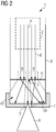
- FIG. 2 shows an X-ray device 1 according to a second embodiment.
- the second embodiment differs from that in FIG. 1 illustrated embodiment only with respect to the extent of the shield 7, so that reference is first made to the relevant description in order to avoid repetition.
- the shield 7 is limited to a portion of the vacuum housing 6.
- the design of the shield 7 is such that at least the majority of the scattered in the edge region B electrons are absorbed by the shield 7.
- a solid angle range ⁇ emanating from the scattering edge region B into which at least the vast majority of electrons are scattered on average is shielded.
- the extent of the shielding 7 is thus interpreted as a function of the kinetic energy of the electrons in accordance with the average scattering angle ⁇ and the mean deviation from this mean scattering angle ⁇ .
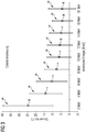
- the relevant for the design of the shield 7 information is in FIG. 3 illustrated for a selected litter material and for certain energy ranges between 2MeV and 18MeV. Shown are each for electron scattering of the respective Energy relevant average scattering angle ⁇ and the mean deviation ⁇ thereof, which is shown as centered around the mean scattering angle ⁇ bar.
- the mean deviation ⁇ here corresponds to the standard deviation, so that in the example illustrated here, assuming normally distributed scattering events, it can be assumed that approximately 68% of the average scattering angle range defined by the mean scattering angle ⁇ and the mean deviation ⁇ is scattered.
- the knowledge of the average scattering angle ranges as a function of the kinetic energy of the incident electrons can be used to specifically design and shield the X-ray device 1 geometrically.
- the solid angle range ⁇ , which the shielding 7 covers, corresponds to the sum of the average scattering angle ranges whose scattering centers lie in the edge region B of the diaphragm 4 which is decisive for the electron scattering.
- the extent of the shield 7 can be significantly reduced by this construction.
- a preferred method for producing the above-described X-ray device 1 comprises a method step in which a component which forms the diaphragm 4 in the final assembled state is introduced into the beam path of the electron beam E provided by the linear accelerator 2.
- the aperture 5 is burned into the component by means of the electron beam E.
- the current intensity of the electron beam provided by the linear accelerator 2 can be increased with respect to the current intensity generated during regular operation. Since the number of electrons is greatly increased due to the focusing properties of the linear accelerator 2 in a central region of the electron beam E and decreases sharply at the edge, such an approach leaves an edge region B surrounding the aperture 5 with the above-described scattering properties.
- Edge-side beam areas of the electron beam E in which the number of electrons in comparison is greatly reduced to the central region of the electron beam E, thus scattered in the regular operation of the X-ray device 1 from the target 3 and so minimizes the expansion of the focal spot on the target 3.
Landscapes
- Physics & Mathematics (AREA)
- High Energy & Nuclear Physics (AREA)
- Spectroscopy & Molecular Physics (AREA)
- Engineering & Computer Science (AREA)
- Chemical Kinetics & Catalysis (AREA)
- Chemical & Material Sciences (AREA)
- General Engineering & Computer Science (AREA)
- Optics & Photonics (AREA)
- Plasma & Fusion (AREA)
- Health & Medical Sciences (AREA)
- General Health & Medical Sciences (AREA)
- Toxicology (AREA)
- Radiation-Therapy Devices (AREA)
- X-Ray Techniques (AREA)
- Particle Accelerators (AREA)
Priority Applications (3)
| Application Number | Priority Date | Filing Date | Title |
|---|---|---|---|
| EP17165888.3A EP3389055B1 (fr) | 2017-04-11 | 2017-04-11 | Équipement à rayons x destiné à la production de rayons x à haute énergie |
| US15/947,934 US10825639B2 (en) | 2017-04-11 | 2018-04-09 | X ray device for creation of high-energy x ray radiation |
| CN201810316877.XA CN108696977B (zh) | 2017-04-11 | 2018-04-10 | 用于产生高能量x射线辐射的x射线设备 |
Applications Claiming Priority (1)
| Application Number | Priority Date | Filing Date | Title |
|---|---|---|---|
| EP17165888.3A EP3389055B1 (fr) | 2017-04-11 | 2017-04-11 | Équipement à rayons x destiné à la production de rayons x à haute énergie |
Publications (2)
| Publication Number | Publication Date |
|---|---|
| EP3389055A1 true EP3389055A1 (fr) | 2018-10-17 |
| EP3389055B1 EP3389055B1 (fr) | 2025-09-24 |
Family
ID=58672310
Family Applications (1)
| Application Number | Title | Priority Date | Filing Date |
|---|---|---|---|
| EP17165888.3A Active EP3389055B1 (fr) | 2017-04-11 | 2017-04-11 | Équipement à rayons x destiné à la production de rayons x à haute énergie |
Country Status (3)
| Country | Link |
|---|---|
| US (1) | US10825639B2 (fr) |
| EP (1) | EP3389055B1 (fr) |
| CN (1) | CN108696977B (fr) |
Families Citing this family (1)
| Publication number | Priority date | Publication date | Assignee | Title |
|---|---|---|---|---|
| CN119846689A (zh) * | 2025-01-07 | 2025-04-18 | 西北核技术研究所 | 一种测量伽马射线能量-时间联合谱的磁谱仪及实现方法 |
Citations (2)
| Publication number | Priority date | Publication date | Assignee | Title |
|---|---|---|---|---|
| GB665998A (en) * | 1948-09-08 | 1952-02-06 | Standard Telephones Cables Ltd | Improvements in or relating to linear accelerators for charged particles |
| DE102012103974A1 (de) | 2011-12-09 | 2013-06-13 | Werth Messtechnik Gmbh | Vorrichtung und Verfahren zur Erzeugung zumindest eines Röntgenstrahlen abgebenden Brennflecks |
Family Cites Families (45)
| Publication number | Priority date | Publication date | Assignee | Title |
|---|---|---|---|---|
| GB645509A (en) * | 1948-09-08 | 1950-11-01 | Standard Telephones Cables Ltd | Improvements in or relating to electromagnetic wave guides |
| DE2425464C3 (de) * | 1974-05-27 | 1978-11-02 | Siemens Ag, 1000 Berlin Und 8000 Muenchen | Verfahren zur Herstellung von Dunnschicht-Aperturblenden für Korpuskularstrahlgeräte |
| US3969629A (en) * | 1975-03-14 | 1976-07-13 | Varian Associates | X-ray treatment machine having means for reducing secondary electron skin dose |
| US4121109A (en) * | 1977-04-13 | 1978-10-17 | Applied Radiation Corporation | Electron accelerator with a target exposed to the electron beam |
| US4140129A (en) * | 1977-04-13 | 1979-02-20 | Applied Radiation Corporation | Beam defining system in an electron accelerator |
| CA1099034A (fr) * | 1977-10-21 | 1981-04-07 | Leonhard Taumann | Accelerateur electronique comprenant une cible exposee au faisceau electronique |
| DE2926841A1 (de) * | 1979-07-03 | 1981-01-22 | Siemens Ag | Elektronenbeschleuniger |
| US4359642A (en) * | 1980-07-14 | 1982-11-16 | Siemens Medical Laboratories, Inc. | Collimator assembly for an electron accelerator |
| DE3138731A1 (de) * | 1981-09-29 | 1983-04-07 | Siemens AG, 1000 Berlin und 8000 München | Ueberwachungsanordnung fuer die beschleunigungsenergie eines elektronenbeschleunigers |
| US4812653A (en) * | 1987-12-01 | 1989-03-14 | Honeywell Inc. | Sharp edge for thick coatings |
| US5033075A (en) * | 1988-05-18 | 1991-07-16 | Rad/Red Laboratories Inc. | Radiation reduction filter for use in medical diagnosis |
| DE3915613A1 (de) * | 1989-05-12 | 1990-11-15 | Berthold Lab Prof R | Kollimator zur messung radioaktiver strahlung |
| US4952814A (en) * | 1989-06-14 | 1990-08-28 | Varian Associates, Inc. | Translating aperture electron beam current modulator |
| JPH07119837B2 (ja) * | 1990-05-30 | 1995-12-20 | 株式会社日立製作所 | Ct装置及び透過装置並びにx線発生装置 |
| JP3022014B2 (ja) * | 1992-01-17 | 2000-03-15 | 三菱電機株式会社 | 光透過型真空分離窓及び軟x線透過窓 |
| US5619042A (en) * | 1995-07-20 | 1997-04-08 | Siemens Medical Systems, Inc. | System and method for regulating delivered radiation in a radiation-emitting device |
| US6333966B1 (en) * | 1998-08-18 | 2001-12-25 | Neil Charles Schoen | Laser accelerator femtosecond X-ray source |
| US6438207B1 (en) * | 1999-09-14 | 2002-08-20 | Varian Medical Systems, Inc. | X-ray tube having improved focal spot control |
| JP3360725B2 (ja) * | 1999-10-19 | 2002-12-24 | 日本電気株式会社 | 電子線露光方法、並びにこれに用いるマスク及び電子線露光装置 |
| US6320936B1 (en) * | 1999-11-26 | 2001-11-20 | Parker Medical, Inc. | X-ray tube assembly with beam limiting device for reducing off-focus radiation |
| US6493421B2 (en) * | 2000-10-16 | 2002-12-10 | Advanced X-Ray Technology, Inc. | Apparatus and method for generating a high intensity X-ray beam with a selectable shape and wavelength |
| US6864633B2 (en) * | 2003-04-03 | 2005-03-08 | Varian Medical Systems, Inc. | X-ray source employing a compact electron beam accelerator |
| JP2005276760A (ja) * | 2004-03-26 | 2005-10-06 | Shimadzu Corp | X線発生装置 |
| US7091486B1 (en) * | 2004-09-09 | 2006-08-15 | Kla-Tencor Technologies Corporation | Method and apparatus for beam current fluctuation correction |
| US7436932B2 (en) * | 2005-06-24 | 2008-10-14 | Varian Medical Systems Technologies, Inc. | X-ray radiation sources with low neutron emissions for radiation scanning |
| CN1997256B (zh) * | 2005-12-31 | 2010-08-25 | 清华大学 | 一种高低能x射线输出装置 |
| US7394082B2 (en) * | 2006-05-01 | 2008-07-01 | Hitachi, Ltd. | Ion beam delivery equipment and an ion beam delivery method |
| GB2460089A (en) * | 2008-05-16 | 2009-11-18 | Elekta Ab | Coincident treatment and imaging source |
| US8208601B2 (en) * | 2008-08-13 | 2012-06-26 | Oncology Tech Llc | Integrated shaping and sculpting unit for use with intensity modulated radiation therapy (IMRT) treatment |
| DE102009007218A1 (de) * | 2009-02-03 | 2010-09-16 | Siemens Aktiengesellschaft | Elektronenbeschleuniger zur Erzeugung einer Photonenstrahlung mit einer Energie von mehr als 0,5 MeV |
| US8269197B2 (en) * | 2009-07-22 | 2012-09-18 | Intraop Medical Corporation | Method and system for electron beam applications |
| JP2011029072A (ja) * | 2009-07-28 | 2011-02-10 | Canon Inc | X線発生装置及びそれを備えたx線撮像装置。 |
| JP5670111B2 (ja) | 2009-09-04 | 2015-02-18 | 東京エレクトロン株式会社 | X線発生用ターゲット、x線発生装置、及びx線発生用ターゲットの製造方法 |
| US8294125B2 (en) | 2009-11-18 | 2012-10-23 | Kla-Tencor Corporation | High-sensitivity and high-throughput electron beam inspection column enabled by adjustable beam-limiting aperture |
| JP5675987B2 (ja) * | 2010-08-27 | 2015-02-25 | ジーイー センシング アンド インスペクション テクノロジーズ ゲ−エムベーハー | 高分解能x線装置用の微小焦点x線管 |
| DE102011005450B4 (de) * | 2011-03-11 | 2013-07-25 | Friedrich-Alexander-Universität Erlangen-Nürnberg | Blende für einen in der Elektronenbestrahlungstherapie einzusetzenden Applikator und Applikator |
| US9330879B2 (en) * | 2011-08-04 | 2016-05-03 | John Lewellen | Bremstrahlung target for intensity modulated X-ray radiation therapy and stereotactic X-ray therapy |
| US8853636B2 (en) * | 2012-02-29 | 2014-10-07 | Elekta Ab (Publ) | Linear accelerators |
| JP6308714B2 (ja) * | 2012-08-28 | 2018-04-11 | キヤノン株式会社 | 放射線発生管および該放射線発生管を備えた放射線発生装置 |
| CN104754848B (zh) * | 2013-12-30 | 2017-12-08 | 同方威视技术股份有限公司 | X射线发生装置以及具有该装置的x射线透视成像系统 |
| CN103889135A (zh) * | 2014-02-18 | 2014-06-25 | 宫良平 | 医用直线加速器kv/mv同轴x射线影像系统 |
| US10453579B2 (en) | 2015-02-05 | 2019-10-22 | Shimadzu Corporation | X-ray generator |
| CN105140088B (zh) | 2015-07-24 | 2017-10-17 | 北京航空航天大学 | 大束流电子束打靶微束斑x射线源的聚焦装置及其使用方法 |
| DE102016013747B4 (de) * | 2016-11-18 | 2018-05-30 | Yxlon International Gmbh | Blende für eine Röntgenröhre und Röntgenröhre mit einer solchen Blende |
| GB2591630B (en) * | 2018-07-26 | 2023-05-24 | Sigray Inc | High brightness x-ray reflection source |
-
2017
- 2017-04-11 EP EP17165888.3A patent/EP3389055B1/fr active Active
-
2018
- 2018-04-09 US US15/947,934 patent/US10825639B2/en active Active
- 2018-04-10 CN CN201810316877.XA patent/CN108696977B/zh active Active
Patent Citations (2)
| Publication number | Priority date | Publication date | Assignee | Title |
|---|---|---|---|---|
| GB665998A (en) * | 1948-09-08 | 1952-02-06 | Standard Telephones Cables Ltd | Improvements in or relating to linear accelerators for charged particles |
| DE102012103974A1 (de) | 2011-12-09 | 2013-06-13 | Werth Messtechnik Gmbh | Vorrichtung und Verfahren zur Erzeugung zumindest eines Röntgenstrahlen abgebenden Brennflecks |
Non-Patent Citations (2)
| Title |
|---|
| ANONYMOUS: "Composition of COPPER", 10 October 2017 (2017-10-10), XP055414377, Retrieved from the Internet <URL:https://physics.nist.gov/cgi-bin/Star/compos.pl?029> [retrieved on 20171010] * |
| ANONYMOUS: "Stopping Power and Range Tables for Electrons", 10 October 2017 (2017-10-10), XP055414376, Retrieved from the Internet <URL:https://physics.nist.gov/cgi-bin/Star/e_table.pl> [retrieved on 20171010] * |
Also Published As
| Publication number | Publication date |
|---|---|
| CN108696977B (zh) | 2022-04-15 |
| EP3389055B1 (fr) | 2025-09-24 |
| CN108696977A (zh) | 2018-10-23 |
| US20180294134A1 (en) | 2018-10-11 |
| US10825639B2 (en) | 2020-11-03 |
Similar Documents
| Publication | Publication Date | Title |
|---|---|---|
| DE69218808T2 (de) | Röntgenuntersuchungsapparat | |
| DE19544203A1 (de) | Röntgenröhre, insbesondere Mikrofokusröntgenröhre | |
| DE7901623U1 (de) | Röntgenröhre | |
| DE102008046288B4 (de) | Elektronenstrahlsteuerung eines Röntgenstrahlers mit zwei oder mehr Elektronenstrahlen | |
| DE112012003176T5 (de) | Elektronenkanone und Ladungsteilchenstrahlvorrichtung | |
| DE2727275C3 (de) | Elektronenbeschleuniger mit einem dem Elektronenstrahl ausgesetzten Target | |
| DE102016013747B4 (de) | Blende für eine Röntgenröhre und Röntgenröhre mit einer solchen Blende | |
| EP0021441B1 (fr) | Accélérateur d'électrons pour radiothérapie aux rayons X | |
| DE2719609A1 (de) | Roentgenroehre | |
| DE102010056321B4 (de) | Partikelstrahlmikroskop | |
| DE102013220189A1 (de) | Röntgenquelle und Verfahren zur Erzeugung von Röntgenstrahlung | |
| EP3389055B1 (fr) | Équipement à rayons x destiné à la production de rayons x à haute énergie | |
| DE60033374T2 (de) | Röntgenmikroskop mit einer röntgenstrahlungsquelle für weiche röntgenstrahlungen | |
| DE102018112054B4 (de) | Röntgenröhre mit Kollimator und Kollimatorvorrichtung für geschlossene Röntgenröhre | |
| WO2013007484A1 (fr) | Source de rayons x monochromatique | |
| EP3599619B1 (fr) | Émetteur de rayons x et procédé de production de rayons x | |
| WO2014177308A1 (fr) | Source de rayons x et système d'imagerie | |
| DE102012221638B4 (de) | Röntgenstrahler | |
| DE102010030713B4 (de) | Röntgenquelle zur Erzeugung von Röntgenstrahlen mit einem Hohlkörpertarget und ein Verfahren zur Erzeugung von Röntgenstrahlung in einem Hohlkörpertarget | |
| DE102008035210B4 (de) | Röntgentarget, Linearbeschleuniger und Verfahren zur Erzeugung von Röntgenstrahlen | |
| WO2017133876A1 (fr) | Dispositif tomographique | |
| DE102015201375A1 (de) | Vorrichtung zur Erzeugung von Röntgenstrahlung in einem äußeren Magnetfeld | |
| DE3934321A1 (de) | Roentgenroehre mit austrittsfenster | |
| DE102005018342B4 (de) | Vorrichtung und Verfahren zur Erzeugung von Röntgenstrahlung | |
| DE2164207C3 (de) | Einrichtung zur Bestrahlung mit energiereichen Elektronen |
Legal Events
| Date | Code | Title | Description |
|---|---|---|---|
| PUAI | Public reference made under article 153(3) epc to a published international application that has entered the european phase |
Free format text: ORIGINAL CODE: 0009012 |
|
| STAA | Information on the status of an ep patent application or granted ep patent |
Free format text: STATUS: THE APPLICATION HAS BEEN PUBLISHED |
|
| AK | Designated contracting states |
Kind code of ref document: A1 Designated state(s): AL AT BE BG CH CY CZ DE DK EE ES FI FR GB GR HR HU IE IS IT LI LT LU LV MC MK MT NL NO PL PT RO RS SE SI SK SM TR |
|
| AX | Request for extension of the european patent |
Extension state: BA ME |
|
| STAA | Information on the status of an ep patent application or granted ep patent |
Free format text: STATUS: REQUEST FOR EXAMINATION WAS MADE |
|
| 17P | Request for examination filed |
Effective date: 20190305 |
|
| RBV | Designated contracting states (corrected) |
Designated state(s): AL AT BE BG CH CY CZ DE DK EE ES FI FR GB GR HR HU IE IS IT LI LT LU LV MC MK MT NL NO PL PT RO RS SE SI SK SM TR |
|
| STAA | Information on the status of an ep patent application or granted ep patent |
Free format text: STATUS: EXAMINATION IS IN PROGRESS |
|
| 17Q | First examination report despatched |
Effective date: 20210413 |
|
| RAP1 | Party data changed (applicant data changed or rights of an application transferred) |
Owner name: SIEMENS HEALTHINEERS AG |
|
| GRAP | Despatch of communication of intention to grant a patent |
Free format text: ORIGINAL CODE: EPIDOSNIGR1 |
|
| STAA | Information on the status of an ep patent application or granted ep patent |
Free format text: STATUS: GRANT OF PATENT IS INTENDED |
|
| RIC1 | Information provided on ipc code assigned before grant |
Ipc: G21K 1/10 20060101ALN20250506BHEP Ipc: H05H 9/04 20060101ALI20250506BHEP Ipc: H05H 6/00 20060101ALI20250506BHEP Ipc: H01J 35/16 20060101ALI20250506BHEP Ipc: H05H 7/00 20060101ALI20250506BHEP Ipc: H01J 35/00 20060101ALI20250506BHEP Ipc: G21K 1/02 20060101AFI20250506BHEP |
|
| INTG | Intention to grant announced |
Effective date: 20250530 |
|
| GRAS | Grant fee paid |
Free format text: ORIGINAL CODE: EPIDOSNIGR3 |
|
| GRAA | (expected) grant |
Free format text: ORIGINAL CODE: 0009210 |
|
| STAA | Information on the status of an ep patent application or granted ep patent |
Free format text: STATUS: THE PATENT HAS BEEN GRANTED |
|
| AK | Designated contracting states |
Kind code of ref document: B1 Designated state(s): AL AT BE BG CH CY CZ DE DK EE ES FI FR GB GR HR HU IE IS IT LI LT LU LV MC MK MT NL NO PL PT RO RS SE SI SK SM TR |
|
| REG | Reference to a national code |
Ref country code: GB Ref legal event code: FG4D Free format text: NOT ENGLISH |
|
| REG | Reference to a national code |
Ref country code: CH Ref legal event code: EP |
|
| REG | Reference to a national code |
Ref country code: DE Ref legal event code: R096 Ref document number: 502017017069 Country of ref document: DE |
|
| REG | Reference to a national code |
Ref country code: IE Ref legal event code: FG4D Free format text: LANGUAGE OF EP DOCUMENT: GERMAN |
|
| PG25 | Lapsed in a contracting state [announced via postgrant information from national office to epo] |
Ref country code: NO Free format text: LAPSE BECAUSE OF FAILURE TO SUBMIT A TRANSLATION OF THE DESCRIPTION OR TO PAY THE FEE WITHIN THE PRESCRIBED TIME-LIMIT Effective date: 20251224 |
|
| REG | Reference to a national code |
Ref country code: LT Ref legal event code: MG9D |
|
| PG25 | Lapsed in a contracting state [announced via postgrant information from national office to epo] |
Ref country code: FI Free format text: LAPSE BECAUSE OF FAILURE TO SUBMIT A TRANSLATION OF THE DESCRIPTION OR TO PAY THE FEE WITHIN THE PRESCRIBED TIME-LIMIT Effective date: 20250924 |
|
| PG25 | Lapsed in a contracting state [announced via postgrant information from national office to epo] |
Ref country code: HR Free format text: LAPSE BECAUSE OF FAILURE TO SUBMIT A TRANSLATION OF THE DESCRIPTION OR TO PAY THE FEE WITHIN THE PRESCRIBED TIME-LIMIT Effective date: 20250924 |
|
| PG25 | Lapsed in a contracting state [announced via postgrant information from national office to epo] |
Ref country code: GR Free format text: LAPSE BECAUSE OF FAILURE TO SUBMIT A TRANSLATION OF THE DESCRIPTION OR TO PAY THE FEE WITHIN THE PRESCRIBED TIME-LIMIT Effective date: 20251225 |
|
| PG25 | Lapsed in a contracting state [announced via postgrant information from national office to epo] |
Ref country code: SE Free format text: LAPSE BECAUSE OF FAILURE TO SUBMIT A TRANSLATION OF THE DESCRIPTION OR TO PAY THE FEE WITHIN THE PRESCRIBED TIME-LIMIT Effective date: 20250924 |
|
| PG25 | Lapsed in a contracting state [announced via postgrant information from national office to epo] |
Ref country code: LV Free format text: LAPSE BECAUSE OF FAILURE TO SUBMIT A TRANSLATION OF THE DESCRIPTION OR TO PAY THE FEE WITHIN THE PRESCRIBED TIME-LIMIT Effective date: 20250924 |
|
| PG25 | Lapsed in a contracting state [announced via postgrant information from national office to epo] |
Ref country code: BG Free format text: LAPSE BECAUSE OF FAILURE TO SUBMIT A TRANSLATION OF THE DESCRIPTION OR TO PAY THE FEE WITHIN THE PRESCRIBED TIME-LIMIT Effective date: 20250924 |
|
| PG25 | Lapsed in a contracting state [announced via postgrant information from national office to epo] |
Ref country code: RS Free format text: LAPSE BECAUSE OF FAILURE TO SUBMIT A TRANSLATION OF THE DESCRIPTION OR TO PAY THE FEE WITHIN THE PRESCRIBED TIME-LIMIT Effective date: 20251224 |
|
| REG | Reference to a national code |
Ref country code: NL Ref legal event code: MP Effective date: 20250924 |
|
| PG25 | Lapsed in a contracting state [announced via postgrant information from national office to epo] |
Ref country code: NL Free format text: LAPSE BECAUSE OF FAILURE TO SUBMIT A TRANSLATION OF THE DESCRIPTION OR TO PAY THE FEE WITHIN THE PRESCRIBED TIME-LIMIT Effective date: 20250924 |
|
| PG25 | Lapsed in a contracting state [announced via postgrant information from national office to epo] |
Ref country code: SM Free format text: LAPSE BECAUSE OF FAILURE TO SUBMIT A TRANSLATION OF THE DESCRIPTION OR TO PAY THE FEE WITHIN THE PRESCRIBED TIME-LIMIT Effective date: 20250924 |
|
| PG25 | Lapsed in a contracting state [announced via postgrant information from national office to epo] |
Ref country code: ES Free format text: LAPSE BECAUSE OF FAILURE TO SUBMIT A TRANSLATION OF THE DESCRIPTION OR TO PAY THE FEE WITHIN THE PRESCRIBED TIME-LIMIT Effective date: 20250924 |
|
| PG25 | Lapsed in a contracting state [announced via postgrant information from national office to epo] |
Ref country code: IT Free format text: LAPSE BECAUSE OF FAILURE TO SUBMIT A TRANSLATION OF THE DESCRIPTION OR TO PAY THE FEE WITHIN THE PRESCRIBED TIME-LIMIT Effective date: 20250924 |
|
| PG25 | Lapsed in a contracting state [announced via postgrant information from national office to epo] |
Ref country code: IS Free format text: LAPSE BECAUSE OF FAILURE TO SUBMIT A TRANSLATION OF THE DESCRIPTION OR TO PAY THE FEE WITHIN THE PRESCRIBED TIME-LIMIT Effective date: 20260124 |
|
| PG25 | Lapsed in a contracting state [announced via postgrant information from national office to epo] |
Ref country code: CZ Free format text: LAPSE BECAUSE OF FAILURE TO SUBMIT A TRANSLATION OF THE DESCRIPTION OR TO PAY THE FEE WITHIN THE PRESCRIBED TIME-LIMIT Effective date: 20250924 Ref country code: PT Free format text: LAPSE BECAUSE OF FAILURE TO SUBMIT A TRANSLATION OF THE DESCRIPTION OR TO PAY THE FEE WITHIN THE PRESCRIBED TIME-LIMIT Effective date: 20260126 |
|
| PG25 | Lapsed in a contracting state [announced via postgrant information from national office to epo] |
Ref country code: PL Free format text: LAPSE BECAUSE OF FAILURE TO SUBMIT A TRANSLATION OF THE DESCRIPTION OR TO PAY THE FEE WITHIN THE PRESCRIBED TIME-LIMIT Effective date: 20250924 |
|
| PG25 | Lapsed in a contracting state [announced via postgrant information from national office to epo] |
Ref country code: SK Free format text: LAPSE BECAUSE OF FAILURE TO SUBMIT A TRANSLATION OF THE DESCRIPTION OR TO PAY THE FEE WITHIN THE PRESCRIBED TIME-LIMIT Effective date: 20250924 Ref country code: EE Free format text: LAPSE BECAUSE OF FAILURE TO SUBMIT A TRANSLATION OF THE DESCRIPTION OR TO PAY THE FEE WITHIN THE PRESCRIBED TIME-LIMIT Effective date: 20250924 |