EP3389121A1 - Stromspeicherelement - Google Patents
Stromspeicherelement Download PDFInfo
- Publication number
- EP3389121A1 EP3389121A1 EP16872617.2A EP16872617A EP3389121A1 EP 3389121 A1 EP3389121 A1 EP 3389121A1 EP 16872617 A EP16872617 A EP 16872617A EP 3389121 A1 EP3389121 A1 EP 3389121A1
- Authority
- EP
- European Patent Office
- Prior art keywords
- active material
- particle diameter
- graphite
- peak
- energy storage
- Prior art date
- Legal status (The legal status is an assumption and is not a legal conclusion. Google has not performed a legal analysis and makes no representation as to the accuracy of the status listed.)
- Granted
Links
Images


Classifications
-
- H—ELECTRICITY
- H01—ELECTRIC ELEMENTS
- H01M—PROCESSES OR MEANS, e.g. BATTERIES, FOR THE DIRECT CONVERSION OF CHEMICAL ENERGY INTO ELECTRICAL ENERGY
- H01M4/00—Electrodes
- H01M4/02—Electrodes composed of, or comprising, active material
- H01M4/36—Selection of substances as active materials, active masses, active liquids
- H01M4/58—Selection of substances as active materials, active masses, active liquids of inorganic compounds other than oxides or hydroxides, e.g. sulfides, selenides, tellurides, halogenides or LiCoFy; of polyanionic structures, e.g. phosphates, silicates or borates
- H01M4/583—Carbonaceous material, e.g. graphite-intercalation compounds or CFx
- H01M4/587—Carbonaceous material, e.g. graphite-intercalation compounds or CFx for inserting or intercalating light metals
-
- H—ELECTRICITY
- H01—ELECTRIC ELEMENTS
- H01G—CAPACITORS; CAPACITORS, RECTIFIERS, DETECTORS, SWITCHING DEVICES, LIGHT-SENSITIVE OR TEMPERATURE-SENSITIVE DEVICES OF THE ELECTROLYTIC TYPE
- H01G11/00—Hybrid capacitors, i.e. capacitors having different positive and negative electrodes; Electric double-layer [EDL] capacitors; Processes for the manufacture thereof or of parts thereof
- H01G11/22—Electrodes
- H01G11/24—Electrodes characterised by structural features of the materials making up or comprised in the electrodes, e.g. form, surface area or porosity; characterised by the structural features of powders or particles used therefor
-
- H—ELECTRICITY
- H01—ELECTRIC ELEMENTS
- H01G—CAPACITORS; CAPACITORS, RECTIFIERS, DETECTORS, SWITCHING DEVICES, LIGHT-SENSITIVE OR TEMPERATURE-SENSITIVE DEVICES OF THE ELECTROLYTIC TYPE
- H01G11/00—Hybrid capacitors, i.e. capacitors having different positive and negative electrodes; Electric double-layer [EDL] capacitors; Processes for the manufacture thereof or of parts thereof
- H01G11/22—Electrodes
- H01G11/30—Electrodes characterised by their material
- H01G11/32—Carbon-based
-
- H—ELECTRICITY
- H01—ELECTRIC ELEMENTS
- H01G—CAPACITORS; CAPACITORS, RECTIFIERS, DETECTORS, SWITCHING DEVICES, LIGHT-SENSITIVE OR TEMPERATURE-SENSITIVE DEVICES OF THE ELECTROLYTIC TYPE
- H01G11/00—Hybrid capacitors, i.e. capacitors having different positive and negative electrodes; Electric double-layer [EDL] capacitors; Processes for the manufacture thereof or of parts thereof
- H01G11/22—Electrodes
- H01G11/30—Electrodes characterised by their material
- H01G11/32—Carbon-based
- H01G11/38—Carbon pastes or blends; Binders or additives therein
-
- H—ELECTRICITY
- H01—ELECTRIC ELEMENTS
- H01G—CAPACITORS; CAPACITORS, RECTIFIERS, DETECTORS, SWITCHING DEVICES, LIGHT-SENSITIVE OR TEMPERATURE-SENSITIVE DEVICES OF THE ELECTROLYTIC TYPE
- H01G11/00—Hybrid capacitors, i.e. capacitors having different positive and negative electrodes; Electric double-layer [EDL] capacitors; Processes for the manufacture thereof or of parts thereof
- H01G11/22—Electrodes
- H01G11/30—Electrodes characterised by their material
- H01G11/32—Carbon-based
- H01G11/42—Powders or particles, e.g. composition thereof
-
- H—ELECTRICITY
- H01—ELECTRIC ELEMENTS
- H01G—CAPACITORS; CAPACITORS, RECTIFIERS, DETECTORS, SWITCHING DEVICES, LIGHT-SENSITIVE OR TEMPERATURE-SENSITIVE DEVICES OF THE ELECTROLYTIC TYPE
- H01G11/00—Hybrid capacitors, i.e. capacitors having different positive and negative electrodes; Electric double-layer [EDL] capacitors; Processes for the manufacture thereof or of parts thereof
- H01G11/84—Processes for the manufacture of hybrid or EDL capacitors, or components thereof
- H01G11/86—Processes for the manufacture of hybrid or EDL capacitors, or components thereof specially adapted for electrodes
-
- H—ELECTRICITY
- H01—ELECTRIC ELEMENTS
- H01M—PROCESSES OR MEANS, e.g. BATTERIES, FOR THE DIRECT CONVERSION OF CHEMICAL ENERGY INTO ELECTRICAL ENERGY
- H01M4/00—Electrodes
- H01M4/02—Electrodes composed of, or comprising, active material
- H01M4/13—Electrodes for accumulators with non-aqueous electrolyte, e.g. for lithium-accumulators; Processes of manufacture thereof
- H01M4/133—Electrodes based on carbonaceous material, e.g. graphite-intercalation compounds or CFx
-
- H—ELECTRICITY
- H01—ELECTRIC ELEMENTS
- H01M—PROCESSES OR MEANS, e.g. BATTERIES, FOR THE DIRECT CONVERSION OF CHEMICAL ENERGY INTO ELECTRICAL ENERGY
- H01M4/00—Electrodes
- H01M4/02—Electrodes composed of, or comprising, active material
- H01M4/13—Electrodes for accumulators with non-aqueous electrolyte, e.g. for lithium-accumulators; Processes of manufacture thereof
- H01M4/139—Processes of manufacture
- H01M4/1393—Processes of manufacture of electrodes based on carbonaceous material, e.g. graphite-intercalation compounds or CFx
-
- H—ELECTRICITY
- H01—ELECTRIC ELEMENTS
- H01M—PROCESSES OR MEANS, e.g. BATTERIES, FOR THE DIRECT CONVERSION OF CHEMICAL ENERGY INTO ELECTRICAL ENERGY
- H01M4/00—Electrodes
- H01M4/02—Electrodes composed of, or comprising, active material
- H01M4/36—Selection of substances as active materials, active masses, active liquids
- H01M4/362—Composites
- H01M4/364—Composites as mixtures
-
- H—ELECTRICITY
- H01—ELECTRIC ELEMENTS
- H01M—PROCESSES OR MEANS, e.g. BATTERIES, FOR THE DIRECT CONVERSION OF CHEMICAL ENERGY INTO ELECTRICAL ENERGY
- H01M4/00—Electrodes
- H01M4/02—Electrodes composed of, or comprising, active material
- H01M4/62—Selection of inactive substances as ingredients for active masses, e.g. binders, fillers
- H01M4/621—Binders
- H01M4/622—Binders being polymers
- H01M4/623—Binders being polymers fluorinated polymers
-
- H—ELECTRICITY
- H01—ELECTRIC ELEMENTS
- H01M—PROCESSES OR MEANS, e.g. BATTERIES, FOR THE DIRECT CONVERSION OF CHEMICAL ENERGY INTO ELECTRICAL ENERGY
- H01M4/00—Electrodes
- H01M4/02—Electrodes composed of, or comprising, active material
- H01M4/62—Selection of inactive substances as ingredients for active masses, e.g. binders, fillers
- H01M4/624—Electric conductive fillers
- H01M4/625—Carbon or graphite
-
- H—ELECTRICITY
- H01—ELECTRIC ELEMENTS
- H01G—CAPACITORS; CAPACITORS, RECTIFIERS, DETECTORS, SWITCHING DEVICES, LIGHT-SENSITIVE OR TEMPERATURE-SENSITIVE DEVICES OF THE ELECTROLYTIC TYPE
- H01G11/00—Hybrid capacitors, i.e. capacitors having different positive and negative electrodes; Electric double-layer [EDL] capacitors; Processes for the manufacture thereof or of parts thereof
- H01G11/10—Multiple hybrid or EDL capacitors, e.g. arrays or modules
-
- H—ELECTRICITY
- H01—ELECTRIC ELEMENTS
- H01G—CAPACITORS; CAPACITORS, RECTIFIERS, DETECTORS, SWITCHING DEVICES, LIGHT-SENSITIVE OR TEMPERATURE-SENSITIVE DEVICES OF THE ELECTROLYTIC TYPE
- H01G11/00—Hybrid capacitors, i.e. capacitors having different positive and negative electrodes; Electric double-layer [EDL] capacitors; Processes for the manufacture thereof or of parts thereof
- H01G11/22—Electrodes
- H01G11/30—Electrodes characterised by their material
- H01G11/46—Metal oxides
-
- H—ELECTRICITY
- H01—ELECTRIC ELEMENTS
- H01G—CAPACITORS; CAPACITORS, RECTIFIERS, DETECTORS, SWITCHING DEVICES, LIGHT-SENSITIVE OR TEMPERATURE-SENSITIVE DEVICES OF THE ELECTROLYTIC TYPE
- H01G11/00—Hybrid capacitors, i.e. capacitors having different positive and negative electrodes; Electric double-layer [EDL] capacitors; Processes for the manufacture thereof or of parts thereof
- H01G11/52—Separators
-
- H—ELECTRICITY
- H01—ELECTRIC ELEMENTS
- H01M—PROCESSES OR MEANS, e.g. BATTERIES, FOR THE DIRECT CONVERSION OF CHEMICAL ENERGY INTO ELECTRICAL ENERGY
- H01M10/00—Secondary cells; Manufacture thereof
- H01M10/05—Accumulators with non-aqueous electrolyte
- H01M10/052—Li-accumulators
- H01M10/0525—Rocking-chair batteries, i.e. batteries with lithium insertion or intercalation in both electrodes; Lithium-ion batteries
-
- H—ELECTRICITY
- H01—ELECTRIC ELEMENTS
- H01M—PROCESSES OR MEANS, e.g. BATTERIES, FOR THE DIRECT CONVERSION OF CHEMICAL ENERGY INTO ELECTRICAL ENERGY
- H01M4/00—Electrodes
- H01M4/02—Electrodes composed of, or comprising, active material
- H01M2004/021—Physical characteristics, e.g. porosity, surface area
-
- H—ELECTRICITY
- H01—ELECTRIC ELEMENTS
- H01M—PROCESSES OR MEANS, e.g. BATTERIES, FOR THE DIRECT CONVERSION OF CHEMICAL ENERGY INTO ELECTRICAL ENERGY
- H01M4/00—Electrodes
- H01M4/02—Electrodes composed of, or comprising, active material
- H01M2004/026—Electrodes composed of, or comprising, active material characterised by the polarity
- H01M2004/027—Negative electrodes
-
- Y—GENERAL TAGGING OF NEW TECHNOLOGICAL DEVELOPMENTS; GENERAL TAGGING OF CROSS-SECTIONAL TECHNOLOGIES SPANNING OVER SEVERAL SECTIONS OF THE IPC; TECHNICAL SUBJECTS COVERED BY FORMER USPC CROSS-REFERENCE ART COLLECTIONS [XRACs] AND DIGESTS
- Y02—TECHNOLOGIES OR APPLICATIONS FOR MITIGATION OR ADAPTATION AGAINST CLIMATE CHANGE
- Y02E—REDUCTION OF GREENHOUSE GAS [GHG] EMISSIONS, RELATED TO ENERGY GENERATION, TRANSMISSION OR DISTRIBUTION
- Y02E60/00—Enabling technologies; Technologies with a potential or indirect contribution to GHG emissions mitigation
- Y02E60/10—Energy storage using batteries
-
- Y—GENERAL TAGGING OF NEW TECHNOLOGICAL DEVELOPMENTS; GENERAL TAGGING OF CROSS-SECTIONAL TECHNOLOGIES SPANNING OVER SEVERAL SECTIONS OF THE IPC; TECHNICAL SUBJECTS COVERED BY FORMER USPC CROSS-REFERENCE ART COLLECTIONS [XRACs] AND DIGESTS
- Y02—TECHNOLOGIES OR APPLICATIONS FOR MITIGATION OR ADAPTATION AGAINST CLIMATE CHANGE
- Y02E—REDUCTION OF GREENHOUSE GAS [GHG] EMISSIONS, RELATED TO ENERGY GENERATION, TRANSMISSION OR DISTRIBUTION
- Y02E60/00—Enabling technologies; Technologies with a potential or indirect contribution to GHG emissions mitigation
- Y02E60/13—Energy storage using capacitors
Definitions
- the present invention relates to an energy storage device such as a lithium ion secondary battery.
- a lithium ion secondary battery that includes a negative electrode having an active material layer containing an active material is known.
- a battery whose active material layer contains, as active materials, a composite carbon material (A) formed by coating a pressure-treated carbon material (a) with a carbonaceous material or a graphite material, and a carbon material (B) (For example, Patent Document 1).
- the pressure-treated carbon material (a) is spherical natural graphite
- the carbon material (B) is one or more selected from natural graphite (C), artificial graphite (D), coated graphite (E) formed by coating a non-pressure-treated raw carbon material with a carbonaceous material or a graphitic material, and non-graphitizing carbon (F).
- the active material layer of the negative electrode contains graphite as an active material, the energy density can be sufficient.
- Patent Document 1 JP-A-2013-201104
- An energy storage device includes a negative electrode containing an active material layer including an active material.
- the active material layer includes particulate graphite as the active material.
- a particle diameter frequency distribution of the graphite includes a first peak and a second peak which appears in a region where a particle diameter is larger than a particle diameter of the first peak, the particle diameter of the first peak is equal to or less than 10 ⁇ m and the particle diameter of the second peak is more than 10 ⁇ m.
- the active material layer further includes a particulate high hardness active material which has higher hardness than the graphite.
- the energy storage device can have sufficient energy density and sufficient power.
- the high hardness active material may include particulate non-graphitizing carbon.
- the energy storage device can have more sufficient energy density and more sufficient power.
- an average particle diameter of the high hardness active material may be more than 10 ⁇ m.
- the particle diameter of the first peak is equal to or less than 10 ⁇ m and an average particle diameter of the high hardness active material is more than 10 ⁇ m, therefore the active material layer includes graphite smaller than the high hardness active material. Accordingly, the graphite which is relatively small can enter a gap between the high hardness active materials approaching each other, and the active material is sufficiently filled in the active material layer. Therefore, the energy storage device can surely have sufficient energy density.
- the average particle diameter of the high hardness active material may be more than the particle diameter of the second peak.
- the graphite enters a gap between the high hardness active materials approaching each other, and the active material is sufficiently filled in the active material layer. Therefore, the above energy storage device can surely have sufficient energy density.
- the graphite includes a pore in an inside thereof.
- a discharge reaction may occur on an inner surface in addition to an outer surface of the graphite because the graphite includes a pore in the inside thereof.
- the power can be large due to a contribution of the discharge reaction on the inner surface. Accordingly, the energy storage device has surely sufficient power.
- the energy storage device having sufficient energy density and sufficient power can be provided.
- the energy storage device is a primary battery, a secondary battery, capacitor or the like.
- the secondary battery capable of discharging and charging will be explained.
- the terms of constitutional members (constitutional elements) are for the present embodiment and may be different from the terms of constitutional members (constitutional elements) in Background Art.
- the energy storage device1 is a nonaqueous secondary battery. Specifically, the energy storage device is a lithium ion secondary battery using an electron transfer which occurs with a lithium ion transfer.
- the energy storage device1 provide an electrical energy.
- the energy storage device1 is used singly or plurally. Specifically, the energy storage device1 is used singly when required power and voltage are low.
- the energy storage device1 is used for an energy storage apparatus100 in combination with other energy storage device1 when at least one of the required power and voltage is large. In the energy storage appratus100, the energy storage device1 used in the energy storage appratus100 provides an electrical energy.
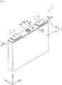
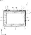
- the energy storage device1 includes an electrode assembly including a positive electrode11 and a negative electrode12, a case3 housing the electrode assembly2, and an external terminal 7 which is disposed outside the case3 and electrically connected with the electrode assembly2.
- the energy storage device1 includes a current collector5 which electrically connects the electrode assembly2 with the external terminal7 or the like in addition to the electrode assembly2, the case3 and the external terminal7.
- the electrode assembly 2 is formed by winding a layered product 22 in a state where the positive electrode 11 and the negative electrode 12 are electrically isolated each other by a separator4.
- the positive electrode11 includes a metal foil111 (positive substrate) and an active material layer112 which is disposed on a surface of the metal foil111 and includes an active material.
- the active material layers112 are layered on each surface of the metal foil111.
- the active material layers112 are disposed on both surfaces in a thickness direction of the metal foil111.
- a thickness of the positive electrode is normally 40 ⁇ m or more and 150 ⁇ m or less.
- the metal foil 111 has a band shape.
- the metal foil 111 of the positive electrode 11 of the present embodiment is, for example, an aluminum foil.
- the positive electrode 11 has a portion 115 not coated with the positive active material layer 112 (a portion where no positive active material layer is formed) at one edge portion in the width direction which is a short side direction of the band shape.
- the positive active material layer 112 includes a particulate active material, a particulate conduction aid, and a binder.
- the active material of the positive electrode 11 is a compound capable of absorbing and releasing lithium ions.
- a thickness of the positive active material layer 112 (for one layer) is usually 15 ⁇ m or more and 70 ⁇ m or less.
- a weight per unit area of the positive active material layer 112 (for one layer) is 5 mg/cm 2 or more and 25 mg/cm 2 or less.
- a density of the positive active material layer 112 is 2 g/cm 3 or more and 4 g/cm 3 or less. The density is a density in one layer disposed so as to cover one surface of the metal foil 111.
- the active material of the positive electrode is, for example, a lithium metal oxide.
- the active material of the positive electrode is, for example, a composite oxide (Li x Ni a O 2 , Li x Co b O 2 , Li x Mn c O 4 , Li x Ni a Co b Mn c O 2 , or the like) represented by Li x MeO e (Me represents one or more transition metal) or a polyanion compound (Li t Fe u PO 4 , Li t Mn u PO 4 , Li t Mn u SiO 4 , Li t Co u PO 4 or the like) represented by Li t Me u (XO v ) w (Me represents one or more transition metal and X represents, for example, P, Si, B or V).
- a composite oxide Li x Ni a O 2 , Li x Co b O 2 , Li x Mn c O 4 , Li x Ni a Co b Mn
- the lithium metal composite oxide represented by the chemical composition of Li x Ni a Co b Mn c M d O e is LiNi 1/3 Co 1/3 Mn 1/3 O 2 , LiNi 1/6 Co 2/3 Mn 1/6 O 2 , LiCoO 2 or the like.
- a binder used in the positive active material layer112 is, for example, polyvinylidene fluoride(PVdF), copolymer of ethylene and vinyl alcohol, polymethylmethacrylate, polyethylene oxide, polypropylene oxide, polyvinyl alcohol, polyacrylic acid, polymethacrylic acid, and stylene-butadien rubber.
- the binder of the present embodiment is polyvinylidene fluoride.
- the conduction aid of the positive active material layer 112 is a carbonaceous material containing carbon in an amount of 98 mass% or more.
- Examples of the carbonaceous material are Ketjen Black (registered trademark), acetylene black, graphite and the like.
- the positive active material layer 112 of the present embodiment has acetylene black as the conduction aid.
- the negative electrode 12 has a metal foil 121 (negative substrate) and a negative active material layer 122 formed on the metal foil 121.
- the negative active material layer 122 is overlaid on both surfaces of the metal foil 121, respectively.
- the metal foil 121 has a band shape.
- the metal foil 121 of the negative electrode of this embodiment is, for example, a copper foil.
- the negative electrode 12 has a portion 125 not coated with the negative active material layer 122 (a portion where no negative active material layer is formed) at one edge portion in the width direction which is a short side direction of the band shape.
- a thickness of the negative electrode 12 (for one layer) is usually 40 ⁇ m or more and 150 ⁇ m or less.
- the negative active material layer 122 includes a particulate active material and a binder.
- the negative active material layer 122 is disposed so as to face the positive electrode 11 with the separator 4 interposed therebetween.
- a width of the negative active material layer 122 is larger than a width of the positive active material layer 112.
- a thickness of the negative active material layer 122 (for one layer) is usually 10 ⁇ m or more and 50 ⁇ m or less.
- a weight per unit area of the negative active material layer 122 (for one layer) is 1 mg/cm 2 or more and 8 mg/cm 2 or less.
- a density of the negative active material layer 122 (for one layer) is usually 1.0 g/cm 3 or more and 1.7 g/cm 3 or less.
- the negative active material layer 122 is formed into a porous state by voids between the active materials.
- a porosity of the negative active material layer 122 is usually 20% or more and 50% or less.
- the porosity is determined from the measurement result by mercury intrusion technique. Specifically, the porosity can be determined by calculation from a true density and bulk volume of the negative active material layer 122 and the pore volume measured by mercury intrusion technique.
- the active material of the negative electrode 12 can contribute to an electrode reaction of a charge reaction and a discharge reaction in the negative electrode 12.
- the active material of the negative electrode 12 include carbon materials such as graphite, non-graphitizing carbon (hard carbon, soft carbon) and the like, and materials capable of causing an alloying reaction with lithium ions, such as silicon (Si) and tin (Sn) and the like.
- carbon materials such as graphite, non-graphitizing carbon (hard carbon, soft carbon) and the like, and materials capable of causing an alloying reaction with lithium ions, such as silicon (Si) and tin (Sn) and the like.
- graphite refers to a carbon material in which an average lattice spacing (d 002) of a (002) plane determined by a wide angle X-ray diffraction method is less than 0.340 nm.
- non-graphitizing carbon means carbon in which a lattice spacing of the (002) plane measured from the wide angle X-ray dif
- the negative active material layer 122 contains graphite and a particulate active material having a higher hardness than graphite (hereinafter also referred to as high hardness active material A) as active materials.
- high hardness active material A non-graphitizing carbon or a material that causes an alloying reaction with lithium ions as described above can be mentioned.
- the negative active material layer 122 contains graphite and non-graphitizing carbon as active materials, and more specifically, graphite and hard carbon as active materials.
- the hardness of the active material is measured by Dynamic Ultramicro Hardness Tester (such as model number "DUH-211S", manufactured by Shimadzu Corporation). The measurement conditions are as follows, for example. The hardness of the active material is indicated by, for example, Vickers hardness.
- Sample Particles are embedded in a resin and fixed with the resin, and the surface of the resin is polished.
- the volume based particle diameter frequency distribution of the graphite contained in the negative active material layer 122 has a first peak and a second peak appearing at a larger particle diameter than that of the first peak.
- a particle diameter of the first peak is 10 ⁇ m or less, and a particle diameter of the second peak is larger than 10 ⁇ m.
- the particle diameter of the peak is a particle diameter at the local maximum point of the peak.
- the particle diameter D1 of the first peak is usually 1 ⁇ m or more and 10 ⁇ m or less, and may be 5 ⁇ m or more.
- the particle diameter D2 of the second peak is usually larger than 10 ⁇ m (exceeds 10 ⁇ m) and 30 ⁇ m or less and may be 20 ⁇ m or less. It should be noted that the relationship between the first peak and the second peak may be satisfied between adjacent peaks, and the particle diameter frequency distribution may have three or more peaks.
- the frequency with respect to the particle diameter of graphite is expressed.
- the particle diameter frequency distribution can be determined by measurement using a laser diffraction-scattering type particle diameter distribution measurement apparatus.
- the particle diameter frequency distribution is determined on a volume basis of particles.
- the electrode active material layer
- a solvent such as N-methylpyrrolidone or water
- the binder of the active material layer is dissolved to dissolve the binder.
- An undissolved matter is separated by filtration and dried.
- graphite 2.2 g/cc
- non-graphitizing carbon 1.5-2.1 g/cc
- the particle diameter frequency distribution of each separated active material is measured using a particle diameter distribution measurement apparatus.
- the particle diameter D1 of the first peak and the particle diameter D2 of the second peak satisfy a relational expression of 1 ⁇ D2/D1 ⁇ 30.
- a value of D2/D1 can be adjusted, for example, by increasing or decreasing the difference in the average particle diameter between graphite materials to be mixed when mixing the graphite materials having different average particle diameters in preparation of the negative electrode 12.
- the value of D2/D1 may be 2 or more and 5 or less, or may be 3 or less.
- the difference between the particle diameter D1 of the first peak and the particle diameter D2 of the second peak is usually 2 ⁇ m or more and 15 ⁇ m or less and may be 10 ⁇ m or less. Such a difference can be adjusted, for example, by increasing or decreasing the difference in the average particle diameter when mixing graphite materials having different average particle diameters in preparation of the negative electrode 12.
- the ratio of the frequency (%) of the local maximum point of the second peak to the frequency (%) of the local maximum point of the first peak is usually 0.1 or more and 1.0 or less.
- Such a ratio can be adjusted, for example, by changing the mixing ratio when mixing graphite materials having different average particle diameters in preparation of the negative electrode 12.
- the proportion of particles having a particle diameter of Dx or less is 10% or more and 50% or less with respect to the whole graphite particles.
- the proportion of particles having a particle diameter equal to or smaller than Dx can be obtained from the ratio of the area of the part having a particle diameter of Dx or less to the total area in the particle diameter frequency distribution.
- the proportion of particles having a particle diameter of Dx or less is usually determined by a software program attached to the particle diameter distribution measurement apparatus described above.
- Examples of the graphite of the active material of the negative electrode 12 include natural graphite and artificial graphite.
- natural graphite include, for example, scale-like graphite and earthy graphite.
- Examples of the scale-like graphite include flaky graphite and the like.
- artificial graphite there can be mentioned, for example, one obtained by baking an organic substance such as coal tar pitch, aromatic hydrocarbon, nitrogen-containing cyclic compound, sulfur-containing cyclic compound and graphitizing it.
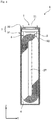
- graphite has a pore in which a part of the outer surface enters into an inside of the graphite. That is, graphite is a particle having a pore Z communicating with a space outside the particle. Therefore, an electrolyte solution described later enters the pore Z, and the electrolyte solution enters the inside of the graphite, and thereby the graphite is impregnated with the electrolyte solution.
- the graphite having the pore Z formed therein has a shape in which flaky natural graphite is folded, for example.
- graphite may be secondary particles in which primary particles are agglomerated. Such secondary particles have pores which have a void between the primary particles and a part of the outer surface enters into an inside of the graphite and have pores communicating with the space outside the secondary particles.
- the negative active material layer 122 usually contains graphite in an amount of 80 mass% or more and 95 mass% or less.
- the negative active material layer 122 usually contains the high hardness active material A as described above in an amount of 3 mass% or more and 10 mass% or less.
- the mass ratio of the graphite to the high hardness active material A is usually 10 or more and 30 or less.
- An average particle diameter of the high hardness active material A contained in the negative active material layer 122 is usually larger than 10 ⁇ m and 25 ⁇ m or less. That is, the average particle diameter of non-graphitizing carbon such as hard carbon is usually larger than 10 ⁇ m and 25 ⁇ m or less.
- the average particle diameter of the high hardness active material A is determined by obtaining the particle diameter corresponding to the cumulative degree of 50% (D50) from the particle diameter frequency distribution measured in the same manner as in the above graphite. Details of the method for measuring the average particle diameter of the high hardness active material A are described in Examples.
- the binder used for the negative active material layer 122 is the same as the binder used for the positive active material layer 112.
- the binder of the present embodiment is polyvinylidene fluoride.
- a ratio of the binder may be 2 mass% or more and 10 mass% or less with respect to the total mass of the negative electrode active material and the binder.
- the positive electrode 11 and the negative electrode 12 configured as described above are wound in a state of being insulated by the separator 4. That is, in the electrode assembly 2 of the present embodiment, a layered product 22 of the positive electrode 11, the negative electrode 12, and the separator 4 is wound.
- the separator 4 is a member having insulating properties.
- the separator 4 is disposed between the positive electrode 11 and the negative electrode 12. Thereby, the positive electrode 11 and the negative electrode 12 are insulated from each other in the electrode assembly 2 (more specifically, the layered product 22). Further, the separator 4 holds the electrolyte solution in a case 3. Thereby, lithium ions move between the positive electrode 11 and the negative electrode 12 which are alternately laminated with the separator 4 interposed therebetween during charge-discharge of the energy storage device 1.
- the separator 4 has a band shape.
- the separator 4 has a porous separator substrate.
- the separator 4 of the present embodiment has only a separator substrate.
- the separator 4 is disposed between the positive electrode 11 and the negative electrode 12 in order to prevent a short circuit between the positive electrode 11 and the negative electrode 12.
- the separator substrate is, for example, formed porous by a fabric, a non-woven fabric, or a porous membrane.
- a material of the separator substrate may be a polymer compound, glass, ceramic or the like.
- the polymer compound may be, for example, polyester such as polyacrylonitrile(PAN), polyamide(PA), polyethyleneterephthalate(PET) or the like, polyolefine(PO) such as polypropylene(PP), polyethylene(PE) or the like, and cellulose.
- the width (dimension in the short side direction of the band shape) of the separator 4 is slightly larger than the width of the negative active material layer 122.
- the separator 4 is disposed between the positive electrode 11 and the negative electrode 12 superimposed in a state of being displaced in the width direction so that the positive active material layer 112 and the negative active material layer 122 overlap with each other. At this time, as shown in Fig. 6 , the uncoated portion 115 of the positive electrode 11 and the uncoated portion 125 of the negative electrode 12 do not overlap.
- the uncoated portion 115 of the positive electrode 11 protrudes in the width direction from the region where the positive electrode 11 and the negative electrode 12 overlap with each other
- the uncoated portion 125 of the negative electrode 12 protrudes in the width direction (a direction opposite to a protrusion direction of the uncoated portion 115 of the positive electrode 11) from the region where the positive electrode 11 and the negative electrode 12 overlap with each other.
- the electrode assembly 2 is formed by winding the positive electrode 11, the negative electrode 12, and the separator 4 in a layered state, that is, the layered product 22.
- An uncoated layered portion 26 of the electrode assembly 2 is composed of the portion where only the uncoated portion 115 of the positive electrode 11 or the uncoated portion 125 of the negative electrode 12 is layered.
- the uncoated layered portion 26 is a portion which is electrically conducted to a current collector 5 in the electrode assembly 2.
- the uncoated layered portion 26 is divided into two portions (a bisected uncoated layered portions) 261 with a hollow portion 27 (see Fig. 6 ) sandwiched therebetween viewed in a direction of a winding central axis of wound the positive electrode 11, the negative electrode 12 and the separator 4.
- the uncoated layered portion 26 configured as described above is provided at each pole of the electrode assembly 2. That is, the uncoated layered portion 26 in which only the uncoated portion 115 of the positive electrode 11 is layered constitutes an uncoated layered portion of the positive electrode 11 in the electrode assembly 2, and the uncoated layered portion 26 in which only the uncoated portion 125 of the negative electrode 12 is layered constitutes an uncoated laminated portion of the negative electrode 12 in the electrode assembly 2.
- the case 3 has a case main body 31 having an opening and a cover plate 32 which blocks (closes) the opening of the case main body 31.
- the case 3 houses the electrolyte solution in an internal space together with the electrode assembly 2, the current collector 5 and the like.
- the case 3 is formed of a metal resistant to the electrolyte solution.
- the case 3 is formed of, for example, an aluminum-based metallic material such as aluminum or an aluminum alloy.
- the case 3 may be made of a metal material such as stainless steel and nickel, or a composite material obtained by bonding a resin such as nylon to aluminum, or the like.
- the electrolyte solution is a nonaqueous solution.
- the electrolyte solution is obtained by dissolving an electrolyte salt in an organic solvent.
- the organic solvent is, for example, a cyclic carbonate ester such as propylene carbonate and ethylene carbonate, a chain carbonate ester such as dimethyl carbonate, diethyl carbonate and ethylmethyl carbonate.
- the electrode salt is LiClO 4 , LiBF 4 , LiPF 6 or the like.
- the electrolyte solution is obtained by dissolving 0.5 to 1.5 mol/L of LiPF 6 in a mixture solvent in which ethylene carbonate, dimethyl carbonate and ethylmethyl carbonate are mixed by a predetermined ratio.
- the case 3 is formed by joining a circumferential edge portion of the opening of the case main body 31 to a peripheral edge portion of the rectangular cover plate 32 in a state of superimposing them. Further, the case 3 has an internal space defined by the case main body 31 and the cover plate 32. In the present embodiment, the circumferential edge portion of the opening of the case main body 31 is joined to the peripheral edge portion of the cover plate 32 by welding.
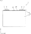
- the long side direction of the cover plate 32 is defined as the X axis direction
- the short side direction of the cover plate 32 is defined as the Y axis direction
- the normal direction of the cover plate 32 is defined as the Z axis direction.
- the case main body 31 has a rectangular cylindrical shape (that is, a bottomed rectangular cylindrical shape) in which one end portion in an opening direction (Z axis direction) is closed.
- the cover plate 32 is a plate-shaped member that blocks the opening of the case main body 31.
- the cover plate 32 has a gas release valve 321 capable of discharging the gas inside the case 3 to the outside.
- the gas release valve 321 discharges the gas from the inside of the case 3 to the outside when the internal pressure of the case 3 rises to a predetermined pressure.
- the gas release valve 321 is provided in the central portion of the cover plate 32 in the X axis direction.
- the case 3 is provided with an electrolyte solution filling hole for filling an electrolyte solution.
- the electrolyte solution filling hole communicates the inside of the case 3 with the outside.
- the electrolyte solution filling hole is provided in the cover plate 32.
- the electrolyte solution filling hole is sealed (blocked) by an electrolyte solution filling plug 326.
- the electrolyte solution filling plug 326 is fixed to the case 3 (the cover plate 32 in the example of the present embodiment) by welding.
- An external terminal 7 is a portion to be electrically connected to the external terminal 7 of another energy storage device 1 or an external device or the like.
- the external terminal 7 is formed of a member having conductivity.
- the external terminal 7 is formed of a metal material having high weldability such as an aluminum-based metal material, for example, aluminum or an aluminum alloy, a copper-based metal material, for example, copper or a copper alloy, or the like.
- the external terminal 7 has a surface 71 on which a bus bar or the like can be welded.
- the surface 71 is a flat surface.
- the external terminal 7 has a plate shape which expands along the cover plate 32. Specifically, the external terminal 7 has a rectangular plate shape as viewed in the Z axis direction.
- the current collector 5 is disposed in the case 3 and is directly or indirectly connected to the electrode assembly 2 so as to be energizable.
- the current collector 5 of the present embodiment is connected to the electrode assembly 2 so as to be energizable via a clip member 50. That is, the energy storage device 1 includes a clip member 50 that connects the electrode assembly 2 and the current collector 5 so as to be energizable.
- the current collector 5 is formed of a member having conductivity. As shown in Fig. 3 , the current collector 5 is arranged along the inner surface of the case 3. The current collector 5 is disposed on each of the positive electrode 11 and the negative electrode 12 of the energy storage device 1. In the energy storage device 1 of the present embodiment, in the case 3, the current collector 5 is disposed on each of the uncoated layered portion 26 of the positive electrode 11 and the uncoated layered portion 26 of the negative electrode 12 of the electrode assembly 2.
- the current collector 5 of the positive electrode 11 and the current collector 5 of the negative electrode 12 are formed of different materials. Specifically, the current collector 5 of the positive electrode 11 is formed of, for example, aluminum or an aluminum alloy, and the current collector 5 of the negative electrode 12 is formed of, for example, copper or a copper alloy.
- the electrode assembly 2 (more specifically, the electrode assembly 2 and the current collector 5) in a state of being housed in a bag-shaped insulating cover 6 that insulates the electrode assembly 2 from the case 3 is housed in the case 3.
- the method for producing the energy storage device 1 first, a composite containing an active material is applied onto a metal foil (electrode substrate) to form an active material layer, and electrodes (positive electrode 11 and negative electrode 12) are produced. Next, the positive electrode 11, the separator 4, and the negative electrode 12 are overlaid to form the electrode assembly 2. Subsequently, the electrode assembly 2 is placed in the case 3, and the electrolyte solution is put in the case 3 to assemble the energy storage device 1.
- a positive active material layer 112 is formed by applying a composite containing an active material, a binder and a solvent onto both surfaces of a metal foil.
- a common method is adopted as an application method for forming the positive active material layer 112.
- the applied positive active material layer 112 is subjected to roll pressing at a predetermined temperature (for example, 80°C to 150°C) and a predetermined pressure (for example, linear pressure of 50 to 500 kg/cm).
- a density of the positive active material layer 112 can be adjusted by adjusting the pressing pressure.
- vacuum drying is carried out at 80°C to 140°C for 12 to 24 hours.
- the negative electrode is also prepared in the same manner.
- the electrode assembly 2 is formed by winding the layered product 22 in which the separator 4 is sandwiched between the positive electrode 11 and the negative electrode 12. Specifically, the positive electrode 11, the separator 4, and the negative electrode 12 are overlaid so that the positive active material layer 112 and the negative active material layer 122 face each other with the separator 4 interposed therebetween to prepare a layered product 22. Subsequently, the layered product 22 is wound to form an electrode assembly 2.
- the electrode assembly 2 In assembling the energy storage device 1, the electrode assembly 2 is placed in the case main body 31 of the case 3, the opening of the case main body 31 is closed with the cover plate 32, and the electrolyte solution is filled into the case 3.
- the electrode assembly 2 When closing the opening of the case main body 31 with the cover plate 32, the electrode assembly 2 is placed inside the case main body 31 to electrically conduct the positive electrode 11 to the one external terminal 7, and the opening of the case main body 31 is closed with the cover plate 32 in a state in which the negative electrode 12 is electrically conducted to the other external terminal 7.
- the electrolyte solution When filling the electrolyte solution into the case 3, the electrolyte solution is filled into the case 3 from the filling hole of the cover plate 32 of the case 3.
- the volume based particle diameter frequency distribution of graphite has a first peak and a second peak appearing at a larger particle diameter than that of the first peak.
- a particle diameter of the first peak is 10 ⁇ m or less, and a particle diameter of the second peak is larger than 10 ⁇ m.
- the particulate graphite G has a pore in which a part of the outer surface enters into an inside of the graphite, and can hold the electrolyte solution in such a pore Z.
- the graphite particles can adequately increase the energy density of the energy storage device 1, but when a pressing pressure is too large in preparing the negative active material layer 122, the particle can be deformed since it has a pore Z therein, resulting in a reduction of a volume of the pore Z capable of holding the electrolyte solution.
- the particle diameter frequency distribution of the particulate graphite G has a first peak having a particle diameter of 10 ⁇ m or less and a second peak having a particle diameter larger than 10 ⁇ m.
- the negative active material layer 122 is easily compacted.
- the electrolyte solution enters the inside of the graphite particles, and the entered electrolyte solution can also contribute to the discharge reaction. Therefore, the above energy storage device 1 can have sufficient energy density and sufficient power.
- the negative active material layer 122 contains, as active materials, graphite and the particulate high hardness active material A (non-graphitizing carbon) having higher hardness than graphite. As the charge-discharge reaction of the energy storage device 1 occurs, the active material repeatedly expands and contracts. Thereby, the negative active material layer 122 undergoes compressive force, and the graphite G having the pore Z inside is pressed, and the volume of the pore Z may decrease.
- the negative active material layer 122 further contains the high hardness active material A (non-graphitizing carbon), it is possible to prevent the comparatively soft graphite particles from deforming beyond a predetermined amount of deformation by the high hardness active material A (non-graphitizing carbon) having a higher hardness than the graphite.
- a reduction in the amount of electrolyte solution that graphite can hold inside can be suppressed by such an extent that the deformation of graphite particles can be suppressed. Accordingly, as with the above description, the above-mentioned energy storage device 1 can have more sufficient energy density and more sufficiently power.
- the case where the high hardness active material A is non-graphitizing carbon has a smaller change in volume of the high hardness active material due to charge-discharge than that in the case where the high hardness active material A is a material that causes an alloying reaction with lithium ions as described above, and the former case can suppress the brittleness of the high hardness active material A more than the latter case.
- the average particle diameter of the high hardness active material A is larger than 10 ⁇ m. That is, the negative active material layer 122 contains graphite smaller than the high hardness active material A. Thereby, small graphite is more likely to be filled in the gaps between the particles of the high hardness active material A. As a result, deformation of relatively soft and small graphite G beyond a predetermined amount of deformation can be suppressed. Therefore, it is possible to suppress a reduction of a volume of the pore Z inside the graphite.
- the above energy storage device 1 can surely have sufficient energy density by such an extent that the reduction of a volume of the pore Z into which the electrolyte solution enters can be suppressed and a discharge reaction via the electrolyte solution can be ensured inside the graphite.
- the energy storage device of the present invention is not limited to the above-mentioned embodiment, and it is obvious that various modifications may be made without departing from the gist of the invention.
- the configuration of another embodiment can be added to the configuration of one embodiment, and a part of the configuration of one embodiment can be replaced with the configuration of another embodiment.
- a part of the configuration of one embodiment can be deleted.
- the particle diameter frequency distribution of the graphite has a first peak appearing at a smaller particle diameter and a second peak appearing at a larger particle diameter, and the first peak and the second peak are adjacent to each other.
- the first peak and the second peak are not necessarily adjacent to each other. For example, even if a small peak having a lower frequency (lower peak height) than any of the first peak and the second peak appears between these two peaks while the first peak and the second peak satisfy each condition of the particle diameter of the above-mentioned peak, the peaks appearing on both sides of such a small peak may be set as the first peak and the second peak, respectively.
- the positive electrode in which the active material layer is in direct contact with the metal foil has been described in detail.
- the positive electrode may have a conductive layer containing a conduction aid and a binder between the active material layer and the metal foil.
- the positive electrode 11 or the negative electrode 12 may include the active material layer only on one surface of the metal foil.
- the energy storage device 1 provided with the electrode assembly 2 formed by winding the layered product 22 has been described in detail, but the energy storage device of the present invention may be provided with the layered product 22 not wound.
- the energy storage device may include an electrode assembly in which the positive electrode, the separator, the negative electrode, and the separator each formed in a rectangular shape are stacked in this order plural times.
- the energy storage device 1 is used as a nonaqueous electrolyte secondary battery (for example, a lithium ion secondary battery) that can be charged and discharged has been described, but the type and the size (capacity) of the energy storage device 1 are optional.
- the lithium ion secondary battery has been described as an example of the energy storage device 1, but the present invention is not limited thereto.
- the present invention can be applied to various secondary batteries, other primary batteries, and energy storage devices of capacitors such as electric double layer capacitors and lithium ion capacitors.
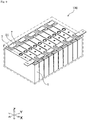
- the energy storage device 1 (for example, a battery) may be used for the energy storage apparatus 100 (a battery module in the case where the energy storage device is a battery) as shown in Fig. 9 .
- the energy storage apparatus 100 includes at least two energy storage devices 1 and a bus bar member 91 for electrically connecting the two (different) energy storage devices 1 to each other.
- the technique of the present invention may be applied to at least one energy storage device.
- a nonaqueous electrolyte secondary battery (lithium ion secondary battery) was produced as follows.
- N-methyl-2-pyrrolidone (NMP) as a solvent, a conduction aid (acetylene black), a binder (PVdF), and particles of an active material (LiNi 1/3 Co 1/3 Mn 1/3 O 2 ) having an average particle diameter D50 of 10 ⁇ m were mixed and kneaded to prepare a composite for positive electrode.
- the compounding amounts of the conduction aid, the binder, and the active material were set to 5 mass%, 5 mass%, and 90 mass%, respectively.
- the prepared composite for the positive electrode was applied onto a metal foil so that an application amount after drying (weight per unit area) was 8 mg/cm 2 . After drying, roll pressing was performed. Thereafter, the composite was vacuum-dried to remove moisture and the like.
- a thickness of the active material layer (for one layer) after pressing was 30 ⁇ m.
- a density of the active material layer was 2.5 g/cm 3 .
- the active material two types of particulate graphite having different average particle diameters and particulate non-graphitizing carbon (hard carbon) were used. Details of the active material are as follows.
- a binder PVdF was used as a binder.
- a composite for the negative electrode was prepared by mixing and kneading NMP as a solvent, a binder, and an active material. The binder was mixed so as to be 7 mass%, and the active materials were mixed so as to be 93 mass% in total. In the active material, the mass ratio between graphite having a smaller particle diameter and graphite having a larger particle diameter was 2 : 7.
- the prepared composite for the negative electrode was applied onto both surfaces of a copper foil (10 ⁇ m thickness) so that an application amount after drying (weight per unit area) was 4.0 mg/cm 2 . After drying, roll pressing was performed and vacuum drying was performed to remove moisture and the like. A thickness of the active material layer (for one layer) was 35 ⁇ m. A density of the active material layer was 1.2 g/cm 3 . A porosity of the active material layer was 40%.
- a microporous polyethylene membrane having a thickness of 22 ⁇ m was used as a separator.
- An air permeability of the microporous polyethylene membrane was 100 second/100 cc.
- electrolyte solution one prepared by the following method was used. Using a solvent in which 1 part by mass of each of ethylene carbonate, dimethyl carbonate, and ethyl methyl carbonate was mixed as a nonaqueous solvent, LiPF 6 was dissolved in the nonaqueous solvent such that the salt concentration was 1 mol/L, electrolysis to prepare an electrolyte solution.
- a battery was produced by a general method using the positive electrode, the negative electrode, the electrolyte solution, and the separator described above, and a case.
- a sheet-like material in which a separator was disposed between the positive electrode and the negative electrode and layered was wound.
- the wound electrode assembly was placed in a case main body of a prismatic container case made of aluminum as a case.
- the positive electrode and the negative electrode were electrically connected to the two external terminals, respectively.
- a cover plate was attached to the case main body.
- the above electrolyte solution was filled into the case from the electrolyte solution filling hole formed on the cover plate of the case.
- the case was sealed by sealing the electrolyte solution filling hole of the case.
- the active material layer of the negative electrode was taken out from the battery once produced.
- the active material layer was immersed in a solvent (N-methylpyrrolidone, NMP) that dissolves the binder of the active material layer to dissolve the binder.
- NMP N-methylpyrrolidone
- An undissolved material was separated by filtration and dried. Thereafter, the particle diameter frequency distribution of the active material was measured using a particle diameter distribution measurement apparatus.
- a laser diffraction type particle diameter distribution measurement apparatus (“SALD 2200" manufactured by Shimadzu Corporation) was used as a measurement apparatus, and a dedicated application software DMS ver. 2 was used as a measurement control software program.
- a scattering type measurement mode was adopted, a wet cell in which a dispersion liquid containing a measurement sample (active material) dispersed therein circulates was placed in an ultrasonic environment for 2 minutes, and then was irradiated with laser light to obtain scattered light distribution from the measurement sample. Then, the scattered light distribution was approximated by a log-normal distribution, and the particle diameter was measured within a range where the minimum was set to 0.021 ⁇ m and the maximum was set to 2000 ⁇ m in the particle diameter frequency distribution (horizontal axis, ⁇ ) to obtain a particle diameter frequency distribution.
- the dispersion also contains a surfactant and SN Dispersant 7347-C (product name) or Triton X-100 (product name) as a dispersant. Several drops of the dispersant were added to the dispersion liquid.
- the graphite (2.2 g/cc) and the hard carbon (1.5-2.1 g/cc) as active materials are separated using a centrifugal separator or a specific gravity gradient tube.
- the particle diameter at the local maximum point of the peak with the smaller particle diameter was taken as the particle diameter D1 of the first peak.
- the particle diameter D1 was 8 ⁇ m.
- the particle diameter at the local maximum point of the peak with the larger particle diameter was taken as the particle diameter D2 of the second peak.
- the particle diameter D2 was 18 ⁇ m.
- a lithium ion secondary battery was produced in the same manner as in Example 1 except that the battery was changed to have the constitution shown in Table 1.
- a particle diameter was measured in the same manner as in the measurement of the particle diameter frequency distribution of graphite except that hard carbon was separated from the active material.
- the particle diameter corresponding to the cumulative degree of 50% (D50) in the particle diameter frequency distribution was taken as the average particle diameter.
- the above mass ratio between graphite having a smaller particle diameter and graphite having a larger particle diameter and the compounding amount of non-graphitizing carbon in the active material layer shown in Table 1 are merely specific examples. As described above, any energy storage device having a particle diameter of the first peak of 10 ⁇ m or less and a particle diameter of the second peak larger than 10 ⁇ m is included in the present invention.
- a lithium ion secondary battery was produced in the same manner as in Example 1 and Example 4 except that the battery was changed so as to have the constitution shown in Table 1.
- the negative active material layer contains graphite and a particulate high hardness active material (non-graphitizing carbon) having higher hardness than graphite as the active material.
- the active material repeatedly expands and contracts. Thereby, the negative active material layer receives a compressive force, and the graphite particles are pressed and deformed.
- the negative active material layer further contains a high hardness active material (non-graphitizing carbon)
- the high hardness active material can suppress, by playing the role of a pillar, deformation of relatively soft graphite particles beyond a predetermined amount of deformation.
Landscapes
- Engineering & Computer Science (AREA)
- Chemical & Material Sciences (AREA)
- Power Engineering (AREA)
- Materials Engineering (AREA)
- Electrochemistry (AREA)
- General Chemical & Material Sciences (AREA)
- Chemical Kinetics & Catalysis (AREA)
- Microelectronics & Electronic Packaging (AREA)
- Composite Materials (AREA)
- Manufacturing & Machinery (AREA)
- Inorganic Chemistry (AREA)
- Battery Electrode And Active Subsutance (AREA)
- Electric Double-Layer Capacitors Or The Like (AREA)
Applications Claiming Priority (2)
| Application Number | Priority Date | Filing Date | Title |
|---|---|---|---|
| JP2015239512 | 2015-12-08 | ||
| PCT/JP2016/005055 WO2017098715A1 (ja) | 2015-12-08 | 2016-12-05 | 蓄電素子 |
Publications (3)
| Publication Number | Publication Date |
|---|---|
| EP3389121A1 true EP3389121A1 (de) | 2018-10-17 |
| EP3389121A4 EP3389121A4 (de) | 2018-12-19 |
| EP3389121B1 EP3389121B1 (de) | 2024-10-23 |
Family
ID=59013974
Family Applications (1)
| Application Number | Title | Priority Date | Filing Date |
|---|---|---|---|
| EP16872617.2A Active EP3389121B1 (de) | 2015-12-08 | 2016-12-05 | Energiespeichervorrichtung |
Country Status (5)
| Country | Link |
|---|---|
| US (1) | US10629909B2 (de) |
| EP (1) | EP3389121B1 (de) |
| JP (1) | JP6950532B2 (de) |
| CN (1) | CN108292752B (de) |
| WO (1) | WO2017098715A1 (de) |
Families Citing this family (3)
| Publication number | Priority date | Publication date | Assignee | Title |
|---|---|---|---|---|
| JP6818235B2 (ja) * | 2017-09-11 | 2021-01-20 | トヨタ自動車株式会社 | 非水電解液二次電池 |
| JP7401208B2 (ja) * | 2019-06-21 | 2023-12-19 | 太陽誘電株式会社 | 全固体電池 |
| WO2021241420A1 (ja) * | 2020-05-26 | 2021-12-02 | パナソニックIpマネジメント株式会社 | 電気化学デバイス用電極および電気化学デバイス |
Family Cites Families (18)
| Publication number | Priority date | Publication date | Assignee | Title |
|---|---|---|---|---|
| JP3440638B2 (ja) | 1995-07-12 | 2003-08-25 | 松下電器産業株式会社 | 非水電解液二次電池 |
| JPH10199526A (ja) * | 1997-01-08 | 1998-07-31 | Asahi Chem Ind Co Ltd | 二次電池 |
| JP3084256B2 (ja) * | 1997-07-03 | 2000-09-04 | 日本カーボン株式会社 | Liイオン二次電池の負極用材 |
| JP3718072B2 (ja) * | 1999-02-04 | 2005-11-16 | 関西熱化学株式会社 | 二次電池の電極材料およびそれを用いた塗布体の製造法 |
| JP4120262B2 (ja) | 2002-02-26 | 2008-07-16 | ソニー株式会社 | 非水電解質電池 |
| KR100477970B1 (ko) * | 2002-12-26 | 2005-03-23 | 삼성에스디아이 주식회사 | 리튬 이차 전지용 음극 활물질 및 그의 제조 방법 |
| JP4152279B2 (ja) | 2003-08-27 | 2008-09-17 | Jfeケミカル株式会社 | リチウムイオン二次電池用負極およびリチウムイオン二次電池 |
| JP2005108611A (ja) * | 2003-09-30 | 2005-04-21 | Sanyo Electric Co Ltd | 非水電解質二次電池 |
| JP4625296B2 (ja) * | 2004-03-31 | 2011-02-02 | 日立マクセル株式会社 | 非水二次電池およびこれを用いた電子機器 |
| JP5119662B2 (ja) | 2006-12-27 | 2013-01-16 | ソニー株式会社 | 負極およびそれを用いた電池 |
| JP2010073618A (ja) * | 2008-09-22 | 2010-04-02 | Sony Corp | 負極および二次電池 |
| JP5322804B2 (ja) | 2009-06-25 | 2013-10-23 | Jfeケミカル株式会社 | リチウムイオン二次電池用負極材料、リチウムイオン二次電池負極およびリチウムイオン二次電池 |
| JP6102074B2 (ja) | 2011-03-29 | 2017-03-29 | 三菱化学株式会社 | 非水系二次電池用負極炭素材、及び負極並びに、非水系二次電池 |
| JP5818068B2 (ja) * | 2011-06-16 | 2015-11-18 | トヨタ自動車株式会社 | 二次電池 |
| JP5802513B2 (ja) * | 2011-10-14 | 2015-10-28 | 株式会社日立製作所 | 二次電池用負極、二次電池用負極を用いた非水電解質二次電池 |
| JP6369739B2 (ja) * | 2013-01-11 | 2018-08-08 | 株式会社Gsユアサ | 蓄電素子及びその製造方法 |
| JP6120093B2 (ja) * | 2014-01-27 | 2017-04-26 | トヨタ自動車株式会社 | 非水電解液二次電池 |
| US10305108B2 (en) * | 2014-03-31 | 2019-05-28 | Nec Energy Devices, Ltd. | Graphite-based active material, negative electrode, and lithium ion secondary battery |
-
2016
- 2016-12-05 WO PCT/JP2016/005055 patent/WO2017098715A1/ja not_active Ceased
- 2016-12-05 JP JP2017554787A patent/JP6950532B2/ja active Active
- 2016-12-05 EP EP16872617.2A patent/EP3389121B1/de active Active
- 2016-12-05 US US15/781,666 patent/US10629909B2/en active Active
- 2016-12-05 CN CN201680071292.5A patent/CN108292752B/zh active Active
Also Published As
| Publication number | Publication date |
|---|---|
| US20190006674A1 (en) | 2019-01-03 |
| JP6950532B2 (ja) | 2021-10-13 |
| US10629909B2 (en) | 2020-04-21 |
| CN108292752A (zh) | 2018-07-17 |
| CN108292752B (zh) | 2021-04-30 |
| EP3389121A4 (de) | 2018-12-19 |
| WO2017098715A1 (ja) | 2017-06-15 |
| JPWO2017098715A1 (ja) | 2018-11-01 |
| EP3389121B1 (de) | 2024-10-23 |
Similar Documents
| Publication | Publication Date | Title |
|---|---|---|
| US9240701B2 (en) | Lithium-ion secondary battery | |
| JP7085156B2 (ja) | 蓄電素子 | |
| EP4443533A1 (de) | Lithiumionen-sekundärbatterie | |
| CN109075317B (zh) | 蓄电元件及其制造方法 | |
| WO2017098716A1 (ja) | 蓄電素子 | |
| CN109844999B (zh) | 蓄电元件和蓄电元件的制造方法 | |
| JPWO2018043375A1 (ja) | 蓄電素子およびその製造方法 | |
| EP3389121B1 (de) | Energiespeichervorrichtung | |
| JP6880488B2 (ja) | リチウムイオン二次電池 | |
| JP2017191651A (ja) | 蓄電素子 | |
| JP6688483B2 (ja) | 蓄電素子の出力の回復方法 | |
| JP2016186886A (ja) | 蓄電素子 | |
| JP2019087448A (ja) | 蓄電素子 | |
| US11217782B2 (en) | Energy storage device | |
| JP2018120829A (ja) | 蓄電素子 | |
| JP6667142B2 (ja) | 蓄電素子 | |
| US12388085B2 (en) | Electrodes comprising blended active materials | |
| JP6946617B2 (ja) | 蓄電素子 | |
| EP4498452A1 (de) | Positivelektrode für eine sekundärbatterie mit wasserfreiem elektrolyt und sekundärbatterie mit wasserfreiem elektrolyt | |
| JP2018055802A (ja) | 蓄電素子 | |
| JP2018098138A (ja) | 蓄電素子 |
Legal Events
| Date | Code | Title | Description |
|---|---|---|---|
| STAA | Information on the status of an ep patent application or granted ep patent |
Free format text: STATUS: THE INTERNATIONAL PUBLICATION HAS BEEN MADE |
|
| PUAI | Public reference made under article 153(3) epc to a published international application that has entered the european phase |
Free format text: ORIGINAL CODE: 0009012 |
|
| STAA | Information on the status of an ep patent application or granted ep patent |
Free format text: STATUS: REQUEST FOR EXAMINATION WAS MADE |
|
| 17P | Request for examination filed |
Effective date: 20180524 |
|
| AK | Designated contracting states |
Kind code of ref document: A1 Designated state(s): AL AT BE BG CH CY CZ DE DK EE ES FI FR GB GR HR HU IE IS IT LI LT LU LV MC MK MT NL NO PL PT RO RS SE SI SK SM TR |
|
| AX | Request for extension of the european patent |
Extension state: BA ME |
|
| A4 | Supplementary search report drawn up and despatched |
Effective date: 20181120 |
|
| RIC1 | Information provided on ipc code assigned before grant |
Ipc: H01M 4/36 20060101ALI20181114BHEP Ipc: H01G 11/42 20130101ALI20181114BHEP Ipc: H01M 4/587 20100101AFI20181114BHEP Ipc: H01G 11/24 20130101ALI20181114BHEP |
|
| RIN1 | Information on inventor provided before grant (corrected) |
Inventor name: ITO, SHOTA Inventor name: SASAKI, TAKESHI Inventor name: SHIMOKAWA, RYOSUKE Inventor name: KAKO, TOMONORI |
|
| DAV | Request for validation of the european patent (deleted) | ||
| DAX | Request for extension of the european patent (deleted) | ||
| STAA | Information on the status of an ep patent application or granted ep patent |
Free format text: STATUS: EXAMINATION IS IN PROGRESS |
|
| 17Q | First examination report despatched |
Effective date: 20210203 |
|
| GRAP | Despatch of communication of intention to grant a patent |
Free format text: ORIGINAL CODE: EPIDOSNIGR1 |
|
| STAA | Information on the status of an ep patent application or granted ep patent |
Free format text: STATUS: GRANT OF PATENT IS INTENDED |
|
| RIC1 | Information provided on ipc code assigned before grant |
Ipc: H01M 4/62 20060101ALI20240626BHEP Ipc: H01M 4/1393 20100101ALI20240626BHEP Ipc: H01M 4/133 20100101ALI20240626BHEP Ipc: H01G 11/38 20130101ALI20240626BHEP Ipc: H01G 11/32 20130101ALI20240626BHEP Ipc: H01M 4/36 20060101ALI20240626BHEP Ipc: H01G 11/42 20130101ALI20240626BHEP Ipc: H01G 11/24 20130101ALI20240626BHEP Ipc: H01M 4/587 20100101AFI20240626BHEP |
|
| INTG | Intention to grant announced |
Effective date: 20240711 |
|
| GRAS | Grant fee paid |
Free format text: ORIGINAL CODE: EPIDOSNIGR3 |
|
| GRAA | (expected) grant |
Free format text: ORIGINAL CODE: 0009210 |
|
| STAA | Information on the status of an ep patent application or granted ep patent |
Free format text: STATUS: THE PATENT HAS BEEN GRANTED |
|
| AK | Designated contracting states |
Kind code of ref document: B1 Designated state(s): AL AT BE BG CH CY CZ DE DK EE ES FI FR GB GR HR HU IE IS IT LI LT LU LV MC MK MT NL NO PL PT RO RS SE SI SK SM TR |
|
| REG | Reference to a national code |
Ref country code: GB Ref legal event code: FG4D |
|
| REG | Reference to a national code |
Ref country code: CH Ref legal event code: EP |
|
| REG | Reference to a national code |
Ref country code: DE Ref legal event code: R096 Ref document number: 602016089977 Country of ref document: DE |
|
| REG | Reference to a national code |
Ref country code: IE Ref legal event code: FG4D |
|
| REG | Reference to a national code |
Ref country code: LT Ref legal event code: MG9D |
|
| REG | Reference to a national code |
Ref country code: NL Ref legal event code: MP Effective date: 20241023 |
|
| REG | Reference to a national code |
Ref country code: AT Ref legal event code: MK05 Ref document number: 1735590 Country of ref document: AT Kind code of ref document: T Effective date: 20241023 |
|
| PG25 | Lapsed in a contracting state [announced via postgrant information from national office to epo] |
Ref country code: NL Free format text: LAPSE BECAUSE OF FAILURE TO SUBMIT A TRANSLATION OF THE DESCRIPTION OR TO PAY THE FEE WITHIN THE PRESCRIBED TIME-LIMIT Effective date: 20241023 |
|
| PG25 | Lapsed in a contracting state [announced via postgrant information from national office to epo] |
Ref country code: NL Free format text: LAPSE BECAUSE OF FAILURE TO SUBMIT A TRANSLATION OF THE DESCRIPTION OR TO PAY THE FEE WITHIN THE PRESCRIBED TIME-LIMIT Effective date: 20241023 |
|
| PG25 | Lapsed in a contracting state [announced via postgrant information from national office to epo] |
Ref country code: IS Free format text: LAPSE BECAUSE OF FAILURE TO SUBMIT A TRANSLATION OF THE DESCRIPTION OR TO PAY THE FEE WITHIN THE PRESCRIBED TIME-LIMIT Effective date: 20250223 Ref country code: HR Free format text: LAPSE BECAUSE OF FAILURE TO SUBMIT A TRANSLATION OF THE DESCRIPTION OR TO PAY THE FEE WITHIN THE PRESCRIBED TIME-LIMIT Effective date: 20241023 Ref country code: PT Free format text: LAPSE BECAUSE OF FAILURE TO SUBMIT A TRANSLATION OF THE DESCRIPTION OR TO PAY THE FEE WITHIN THE PRESCRIBED TIME-LIMIT Effective date: 20250224 |
|
| PG25 | Lapsed in a contracting state [announced via postgrant information from national office to epo] |
Ref country code: FI Free format text: LAPSE BECAUSE OF FAILURE TO SUBMIT A TRANSLATION OF THE DESCRIPTION OR TO PAY THE FEE WITHIN THE PRESCRIBED TIME-LIMIT Effective date: 20241023 |
|
| PG25 | Lapsed in a contracting state [announced via postgrant information from national office to epo] |
Ref country code: BG Free format text: LAPSE BECAUSE OF FAILURE TO SUBMIT A TRANSLATION OF THE DESCRIPTION OR TO PAY THE FEE WITHIN THE PRESCRIBED TIME-LIMIT Effective date: 20241023 |
|
| PG25 | Lapsed in a contracting state [announced via postgrant information from national office to epo] |
Ref country code: ES Free format text: LAPSE BECAUSE OF FAILURE TO SUBMIT A TRANSLATION OF THE DESCRIPTION OR TO PAY THE FEE WITHIN THE PRESCRIBED TIME-LIMIT Effective date: 20241023 |
|
| PG25 | Lapsed in a contracting state [announced via postgrant information from national office to epo] |
Ref country code: NO Free format text: LAPSE BECAUSE OF FAILURE TO SUBMIT A TRANSLATION OF THE DESCRIPTION OR TO PAY THE FEE WITHIN THE PRESCRIBED TIME-LIMIT Effective date: 20250123 |
|
| PG25 | Lapsed in a contracting state [announced via postgrant information from national office to epo] |
Ref country code: LV Free format text: LAPSE BECAUSE OF FAILURE TO SUBMIT A TRANSLATION OF THE DESCRIPTION OR TO PAY THE FEE WITHIN THE PRESCRIBED TIME-LIMIT Effective date: 20241023 Ref country code: GR Free format text: LAPSE BECAUSE OF FAILURE TO SUBMIT A TRANSLATION OF THE DESCRIPTION OR TO PAY THE FEE WITHIN THE PRESCRIBED TIME-LIMIT Effective date: 20250124 Ref country code: AT Free format text: LAPSE BECAUSE OF FAILURE TO SUBMIT A TRANSLATION OF THE DESCRIPTION OR TO PAY THE FEE WITHIN THE PRESCRIBED TIME-LIMIT Effective date: 20241023 |
|
| PG25 | Lapsed in a contracting state [announced via postgrant information from national office to epo] |
Ref country code: PL Free format text: LAPSE BECAUSE OF FAILURE TO SUBMIT A TRANSLATION OF THE DESCRIPTION OR TO PAY THE FEE WITHIN THE PRESCRIBED TIME-LIMIT Effective date: 20241023 |
|
| PG25 | Lapsed in a contracting state [announced via postgrant information from national office to epo] |
Ref country code: RS Free format text: LAPSE BECAUSE OF FAILURE TO SUBMIT A TRANSLATION OF THE DESCRIPTION OR TO PAY THE FEE WITHIN THE PRESCRIBED TIME-LIMIT Effective date: 20250123 |
|
| PG25 | Lapsed in a contracting state [announced via postgrant information from national office to epo] |
Ref country code: SM Free format text: LAPSE BECAUSE OF FAILURE TO SUBMIT A TRANSLATION OF THE DESCRIPTION OR TO PAY THE FEE WITHIN THE PRESCRIBED TIME-LIMIT Effective date: 20241023 |
|
| PG25 | Lapsed in a contracting state [announced via postgrant information from national office to epo] |
Ref country code: MC Free format text: LAPSE BECAUSE OF FAILURE TO SUBMIT A TRANSLATION OF THE DESCRIPTION OR TO PAY THE FEE WITHIN THE PRESCRIBED TIME-LIMIT Effective date: 20241023 |
|
| PG25 | Lapsed in a contracting state [announced via postgrant information from national office to epo] |
Ref country code: DK Free format text: LAPSE BECAUSE OF FAILURE TO SUBMIT A TRANSLATION OF THE DESCRIPTION OR TO PAY THE FEE WITHIN THE PRESCRIBED TIME-LIMIT Effective date: 20241023 |
|
| PG25 | Lapsed in a contracting state [announced via postgrant information from national office to epo] |
Ref country code: EE Free format text: LAPSE BECAUSE OF FAILURE TO SUBMIT A TRANSLATION OF THE DESCRIPTION OR TO PAY THE FEE WITHIN THE PRESCRIBED TIME-LIMIT Effective date: 20241023 |
|
| PG25 | Lapsed in a contracting state [announced via postgrant information from national office to epo] |
Ref country code: RO Free format text: LAPSE BECAUSE OF FAILURE TO SUBMIT A TRANSLATION OF THE DESCRIPTION OR TO PAY THE FEE WITHIN THE PRESCRIBED TIME-LIMIT Effective date: 20241023 |
|
| REG | Reference to a national code |
Ref country code: DE Ref legal event code: R097 Ref document number: 602016089977 Country of ref document: DE |
|
| PG25 | Lapsed in a contracting state [announced via postgrant information from national office to epo] |
Ref country code: SK Free format text: LAPSE BECAUSE OF FAILURE TO SUBMIT A TRANSLATION OF THE DESCRIPTION OR TO PAY THE FEE WITHIN THE PRESCRIBED TIME-LIMIT Effective date: 20241023 |
|
| PG25 | Lapsed in a contracting state [announced via postgrant information from national office to epo] |
Ref country code: CZ Free format text: LAPSE BECAUSE OF FAILURE TO SUBMIT A TRANSLATION OF THE DESCRIPTION OR TO PAY THE FEE WITHIN THE PRESCRIBED TIME-LIMIT Effective date: 20241023 |
|
| PG25 | Lapsed in a contracting state [announced via postgrant information from national office to epo] |
Ref country code: IT Free format text: LAPSE BECAUSE OF FAILURE TO SUBMIT A TRANSLATION OF THE DESCRIPTION OR TO PAY THE FEE WITHIN THE PRESCRIBED TIME-LIMIT Effective date: 20241023 |
|
| REG | Reference to a national code |
Ref country code: CH Ref legal event code: PL |
|
| PG25 | Lapsed in a contracting state [announced via postgrant information from national office to epo] |
Ref country code: LU Free format text: LAPSE BECAUSE OF NON-PAYMENT OF DUE FEES Effective date: 20241205 |
|
| PLBE | No opposition filed within time limit |
Free format text: ORIGINAL CODE: 0009261 |
|
| STAA | Information on the status of an ep patent application or granted ep patent |
Free format text: STATUS: NO OPPOSITION FILED WITHIN TIME LIMIT |
|
| PG25 | Lapsed in a contracting state [announced via postgrant information from national office to epo] |
Ref country code: SE Free format text: LAPSE BECAUSE OF FAILURE TO SUBMIT A TRANSLATION OF THE DESCRIPTION OR TO PAY THE FEE WITHIN THE PRESCRIBED TIME-LIMIT Effective date: 20241023 |
|
| GBPC | Gb: european patent ceased through non-payment of renewal fee |
Effective date: 20250123 |
|
| 26N | No opposition filed |
Effective date: 20250724 |
|
| REG | Reference to a national code |
Ref country code: BE Ref legal event code: MM Effective date: 20241231 |
|
| PG25 | Lapsed in a contracting state [announced via postgrant information from national office to epo] |
Ref country code: BE Free format text: LAPSE BECAUSE OF NON-PAYMENT OF DUE FEES Effective date: 20241231 Ref country code: GB Free format text: LAPSE BECAUSE OF NON-PAYMENT OF DUE FEES Effective date: 20250123 |
|
| PG25 | Lapsed in a contracting state [announced via postgrant information from national office to epo] |
Ref country code: FR Free format text: LAPSE BECAUSE OF NON-PAYMENT OF DUE FEES Effective date: 20241223 |
|
| PG25 | Lapsed in a contracting state [announced via postgrant information from national office to epo] |
Ref country code: CH Free format text: LAPSE BECAUSE OF NON-PAYMENT OF DUE FEES Effective date: 20241231 |
|
| PG25 | Lapsed in a contracting state [announced via postgrant information from national office to epo] |
Ref country code: IE Free format text: LAPSE BECAUSE OF NON-PAYMENT OF DUE FEES Effective date: 20241205 |
|
| PGFP | Annual fee paid to national office [announced via postgrant information from national office to epo] |
Ref country code: DE Payment date: 20251126 Year of fee payment: 10 |
|
| PG25 | Lapsed in a contracting state [announced via postgrant information from national office to epo] |
Ref country code: CY Free format text: LAPSE BECAUSE OF FAILURE TO SUBMIT A TRANSLATION OF THE DESCRIPTION OR TO PAY THE FEE WITHIN THE PRESCRIBED TIME-LIMIT; INVALID AB INITIO Effective date: 20161205 |